


Below ground oil-hydraulic operator for swinging gates
STANDARD VERSION: 110° or 175° Leaf Rotation
•Compact, internal drive unit and hydraulic jack
•Normal version or version with two-way Locking device
•Models with or without hydraulic Brake
•Models with or without flow Regulator
Instructions manual
pages 17-32
17
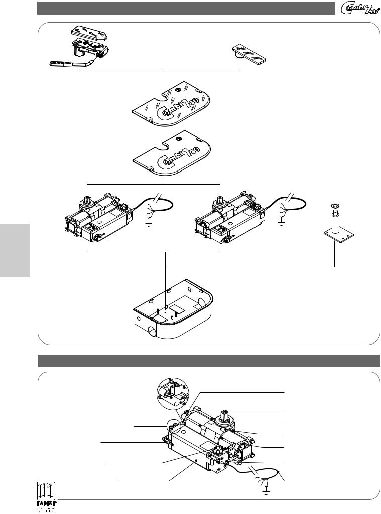
MAIN COMPONENTS OF THE BELOW GROUND OIL-HYDRAULIC GATE OPENER
Emergency manual release with |
|
square ferrule, release key and |
Plate with square ferrule |
welding plate |
|
(for hydraulic jacks with hydraulic locking device) |
(for hydraulic jacks without hydraulic locking device) |
Stainless steel cover (Optional)
 1790
1790
Aluminium enclosure cover
1790
English
Combi 740 110° |
Combi 740 175° |
Gate spacer hinge
Enclosure
(zinc-coated or stainless steel)
PIC. 1
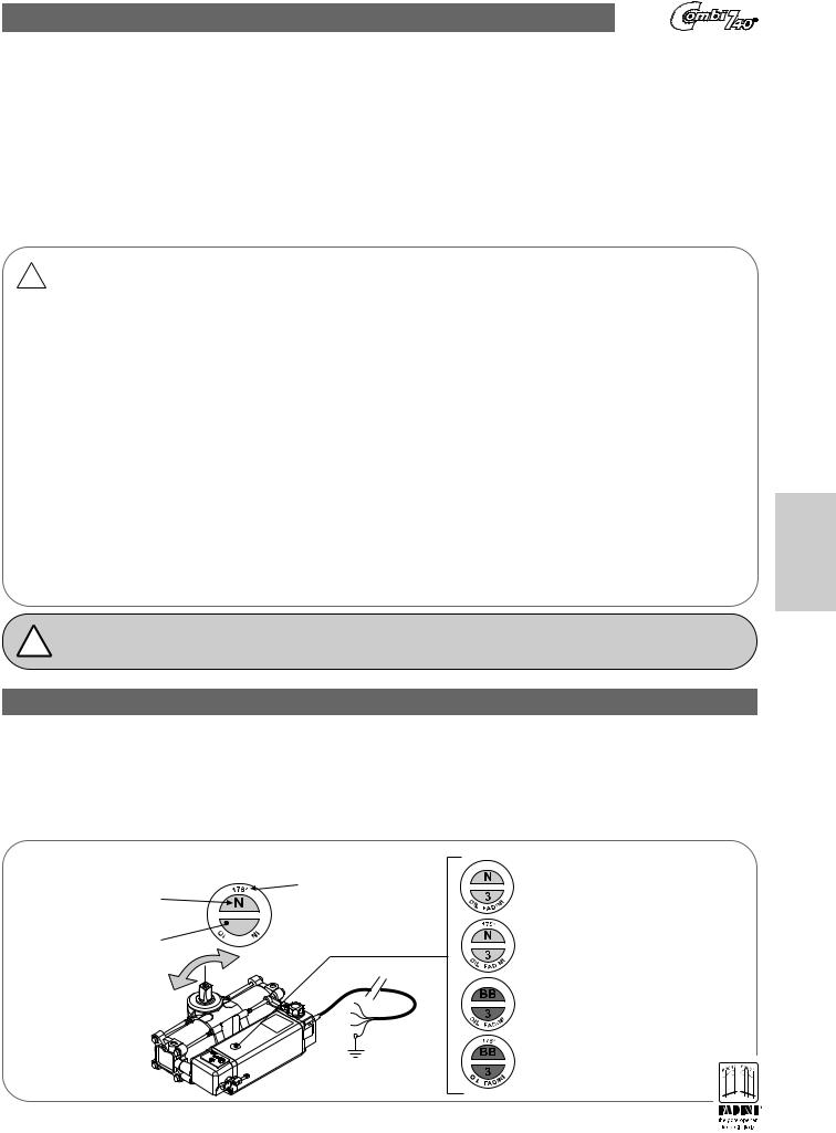
DESCRIPTION OF JACK / MOTOR PUMP COMPONENTS
Flow regulator
(version with Flow 


Regulator)
Maximum and minimum pressure valves in both shaft rotation directions
Hydraulic jack release lever
Oil reservoir plug
Motor pump oil reservoir
Braking adjustment
(Braking version)
|
Rotation shaft |
|
|
Hydraulic jack |
|
Sx |
Combi |
|
|
|
|
|
Right or Left Indication |
|
|
Braking adjustment |
|
|
(Braking version) |
|
|
Flow regulator |
|
|
(version with Flow |
|
|
Regulator) |
|
|
Electric power 4x1mm2 |
|
|
cable 230V |
PIC. 2 |
|
length 2.50 meters |
18
INSTRUCTIONS TO BE FOLLOWED BEFORE INSTALLING THE OPERATOR
TO ENSURE THE PERFECT INSTALLATION AND OPERATION OF THE COMBI 740 ADHERE TO THE FOLLOWING EXPLANATORY POINTS AND RELATIVE DRAWINGS. IMPORTANT: THE ENTIRE INSTALLATION PROCESS MUST BE CARRIED OUT BY QUALIFIED, TECHNICAL PERSONNEL IN COMPLIANCE WITH EN 12453 - EN 12445 SAFETY STANDARDS, AND IN ACCORDANCE WITH MACHINERY DIRECTIVE 2006/42/CE.
CARRY OUT A CAREFUL ANALYSIS OF RISKS IN ACCORDANCE WITH SAFETY REGULATIONS IN FORCE.
GENERAL INFORMATION:
The COMBI 740 is an oil-hydraulic automated operator designed to open and close swinging gates; it is installed below ground at the base of the gate's rotation hinges. It is an oil-hydraulic operator with a built-in hydraulic drive unit; the entire operator is housed inside its enclosure, cemented at the base of the gate leaf. The electronic programmer control is installed externally in a protected area and it controls all possible movement functions automatically or semi-automatically, depending on the client's requirements.
The gate opener includes a number of accessories that ensure necessary safety and manoeuvrability, making this operator suitable for installation in any public or private place.
PRELIMINARY WARNINGS FOR SAFETY AND GOOD SYSTEM OPERATION
!Before installing the operator in the ground, be sure to verify the following:
-Installation, checks, testing, and risk analysis and further maintenance must be carried out by qualified, authorised, technical personnel.
-This automated device was designed for specific use, as indicated in this manual, with safety, control and signalling accessories as minimum required.
-Any use of the operator which is not explicitly stated in this manual may cause operational disruption or damage to property and people.
-Check the consistency of the soil to avoid settling or subsequent deformation in the installation area.
-Ensure that there are no utility lines in the immediate vicinity or underground which may hinder any digging required.
-Ensure that in the immediate vicinity of installation accessories, both above and below ground, there are no sources of electromagnetic disturbance that could hide or influence magnetic/electromagnetic readings from any metal loop detectors and from all electronic control and system management equipment.
-Ensure that the mains power and voltage to the electric motor is 230V±10% 50Hz.
-Combi 740 must be powered with electrical cables having 1mm2 diameter for a maximum distance of 50 meters. For distances longer than 50 meters, the use of electrical cables with appropriate diameter wires is recommended.
-For any replacements of parts or accessories, use original components indicated by the manufacturer.
-All packaging materials must be disposed of by specialised companies. Do not throw away, in normal waste receptacles, any material that may be harmful to the environment.
-Meccanica Fadini is not responsible for any damage caused by improper use, or use not specifically mentioned in this manual, and is not liable for malfunctions resulting from the use of materials or accessories not provided by the company itself.
-The manufacturer reserves the right to make changes to this manual without prior notice.
English
! |
Meccanica Fadini, the manufacturer, is not responsible for installations failing to comply with correct installation and application |
technique and for applications not included in this manual. |
VERSIONS OF THE COMBI 740 OIL-HYDRAULIC OPERATOR
110° Version = underground swing gate opener with 110° maximum leaf rotation. 175° Version = underground swing gate opener with 175° maximum leaf rotation.
Normal version = 110° and 175° non locking in the two movement directions. Use of an electric lock is always recommended. Locking version = 110° and 175° locking in the two movement directionss.
Version with Brake = 110° and 175° rotation with adjustable hydraulic braking in the two movement directions, during the last 40 cm (approx.) ofmovement. Version with Flow Regulator = 110° and 175° rotation with adjustment of hydraulic flow (controls the leaf speed) in the two movement directions for leafslonger than
2.5 meters.
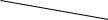
Combi 740 version and rotation identification sticker
|
Maximum leaf |
Version (Normal or Locking) |
open rotation |

 Hydraulic pump type Colour: Blue (Normal)


Colour: Red (Locking)
Maximum shaft rotation:
110° or 175°
PIC.3
Combi 740 110° Normal
(blue sticker)
Combi 740 175° Normal
(blue sticker)
Combi 740 110° Locking
(red sticker)
Combi 740 175° Locking
(red sticker)
19

MAIN COMPONENTS FOR STANDARD INSTALLATION
English
|
|
Right gate |
|
|
Left gate |
|
Dx |
|
|
|
|
Sx |
Gate close stop |
|
The abbreviation “Dx” |
|
|
||
|
|
|
|
|
|
|
indicates |
|
|
Right Combi 740 |
the Right Combi 740 |
The abbreviation “Sx” |
|
|
(as seen from inside |
|
|
the property) |
|
indicates |
Left Combi 740 |
|
|
the Left Combi 740 |
|
|
|
(as seen from inside |
|
|
Right gate open stop |
the property) |
|
|
|
|
|
(not provided by the manufacturer) |
|
|
|
|
|
|
Left gate open stop |
|
|
(not provided by the manufacturer) |
|
|
|
Support plate |
Manual release |
Manual release |
Support plate |
with ferrule |
Left |
Right |
with ferrule |
Left |
|
|
Right |
Combi 740 |
|
|
Combi 740 |
Left |
|
|
Right |
Normal |
VIEW FROM BELOW |
VIEW FROM BELOW |
Normal |
enclosure |
enclosure |
||
PIC. 4
Important: For installations with Combi 740 (Normal or Locking) with leafs longer than 2.0 meters it is always necessary to install an
!Electric lock or a Leaf stop bolt: the possible solutions are shown in Pic. 5 and Pic. 6. For a single leaf, it is recommended that the electric lock be installed horizontally.
 Electric lock catch plate to be secured on the first leaf that closes,
or on the wall with single leaf gates
|
Gate close stop bolt |
|
|
|
welded on the |
|
|
|
first leaf that closes |
|
|
“Horizontal” Electric lock |
Gate close stop |
Gate close |
|
stop |
|||
on the second leaf that closes. |
to be secured to the ground |
||
|
|||
For single-leaf gates |
Vertical |
Electric lock catch plate |
|
this solution is recommended |
application of the |
||
|
Electric lock |
to be secured to the ground |
|
|
PIC. 5 |
PIC. 6 |
20
IDEAL USE OF THE COMBI 740 BELOW GROUND OIL-HYDRAULIC OPERATOR
-Combi 740 Normal version, 110° rotation:
1)The Combi 740 110° can be used on any leaf, always with an electric lock.
2)For leafs longer than 2.50 meters use of the Combi 740 with brake is recommended.
3)For special 4.0 and 5.0 meter leafs a Flow regulator must be installed.
4)The static weight that the Combi 740 can bear is 700Kg, for a 1.0 meter long leaf. If this length is exceeded the weight of the leaf must be decreased (Pic.7).
-Combi 740 locking version, 110° rotation:
All previous four points apply.
5)The Combi 740 Locking is recommended for leafs up to 2.0 meters long, without an electric lock. Anelectriclockisalwaysnecessaryforleafsthatarelongerthan2.0meters.
-Combi 740 Normal version, 175° rotation:
All previous four points apply.
- Combi 740 Locking version, 175° rotation:
All previous five points apply.
1.0m |
2.0m |
3.0m |
4.0m |
700Kg |
400Kg |
300Kg |
250Kg |
|
|
|
|
|
|
|
|
|
|
|
|
COMBI 740 |
|
|
|||
Maximum leaf length 1.0 meter |
|
Maximum weight 700 Kg |
|||
|
|||||
Maximum leaf length 2.0 meters |
|
Maximum weight 400 Kg |
|||
|
|||||
Maximum leaf length 3.0 meters |
|
Maximum weight 300 Kg |
|||
|
|||||
Maximum leaf length 4.0 meters |
|
Maximum weight 250 Kg |
|||
|
|||||
PIC. 7
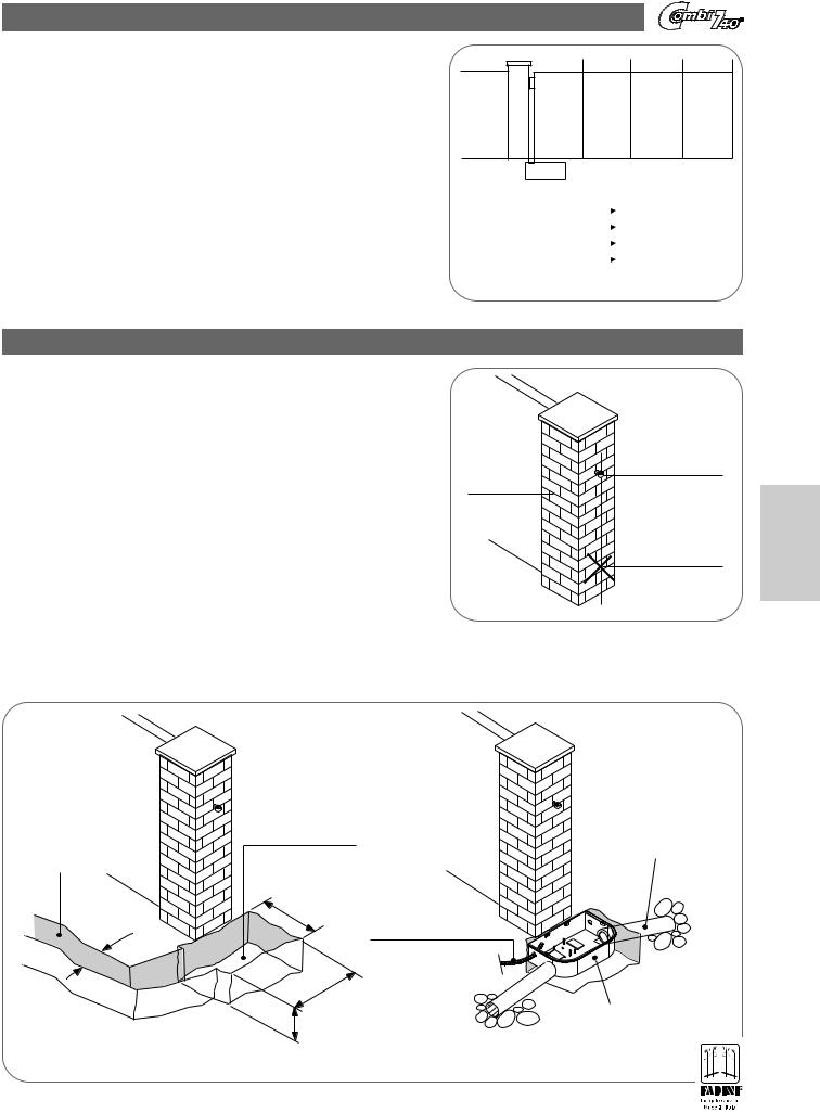
INSTALLING THE ENCLOSURE
WARNINGS: ensure that the gate structure is suited to the operator and check to see if the fixed and moving parts require any special reinforcements for installation, making sure that there are no obstacles or friction during the entire movement of the leaf.
The normal enclosure must be cemented to the base of the gate in order to receive and secure the operator. However, the lower leaf hinge must be removed first because the Combi 740 rotation shaft acts as a lower rotation hinge (Pic.8).
Top hinge
Brickwork
Remove the lower hinge
(if present)
PIC. 8
SETTING UP AND SECURING THE ENCLOSURE
Dig a hole at the base of the column in accordance with the measurements indicated in Pic.9. At the same time, pre-set an underground pipe to connect the enclosure to the installation site of the Electronic programmer (it is recommended that the Programmer be installed in a protected and dry place); the pipe must be of a suitable diameter to permit the passage of the operator's power cables (corrugated pipe Ø20 - Ø25mm).
English
|
|
|
Set up drainage piping |
Hole for piping |
Hole for normal |
|
that directs |
enclosure housing |
|
rainwater outside |
|
to the electronic |
|
||
|
|
the enclosure |
|
programmer |
|
|
|
|
|
|
|
|
350 |
Underground piping |
|
|
for the passage of |
|
|
|
50 |
the electric power |
|
|
cable |
|
|
|
500 |
|
|
|
220 |
|
Normal enclosure |
|
|
installed flush with |
|
PIC. 9 |
|
Layer of gravel |
the ground |
|
for fluid drainage |
|
21
 Loading...