


Rolling-code
-DA INNESTO
-PLUG-IN
-ENFICHABLE
-EINSTECKVERSION
-ENCHUFABLE
-MET KOPPELING
3
R°2
R°1
|
|
3 |
2 |
1 |
5 |
4 |
|
||
|
|
|
ANTENNA
11 
10
-Cod. Art. 8611 -

 0678
0678
2 |
2 |
|
|
PIN |
|
|
|
|
|
|
|
1 |
|
(C1) |
C2 |
1 |
2 |
|
|
|
|
P1 |
° |
P2 |
|
|
|
|
||||
|
|
|
|
|
|
|||||
1 |
1 |
|
|
P1 |
|
|
|
|
|
|
|
|
|
C1 |
|
|
|
|
|
|
|
|
|
|
|
|
|
|
|
|
|
|
“STRIP” |
“STRIP” |
|
|
|
|
|
|
|
||
|
|
|
4 |
|
|
|
|
|
|
|
“STRIP” |
“STRIP” |
|
|
|
|
|
|
|
||
|
|
|
|
|
R°2 |
|
|
|
|
|
|
2 |
|
|
|
R°1 |
|
|
|
|
|
2 |
|
|
|
|
|
|
|
2 |
1 |
|
|
|
(C2) |
|
|
|
|
3 |
|||
P2 |
2° |
|
– + |
|
4 |
|
||||
|
5 |
|
|
|||||||
|
|
|
|
|
||||||
|
|
|
|
|
|
|
|
|
|
|
1 |
1 |
|
|
|
|
|
|
|
|
|
|
|
|
9 |
8 |
7 |
NC |
|
NA |
|
|
|
|
|
|
|
|
|
||||
|
|
|
|
|
|
|
|
|||
02-2009
5
6
Fig.1
I |
a) CONOSCERE LA MEMORIA LIBERA -P1- |
DESCRIZIONE COMPONENTI Fig.1 |
|
|
1 |
- Memoria estraibile |
|
|
Per conoscere quanta memoria libera è disponibile nella ricevente, con la scheda alimentata |
2 |
- Pulsante “P” |
a 24 Volt, si deve inserire il ponticello “STRIP” nella posizione “P1” e premere il pulsante “P” |
3 |
- Inserto di contatto “STRIP” ponticelli |
|
per cinque secondi: rilasciandolo si possono notare dei lampeggi. Ad ogni lampeggio di led |
4 |
- Ponticelli 1°-2° canale: scelta da 1 a 4 |
|
corrispondono 180 trasmettitori che si possono ancora memorizzare. |
|
pulsanti del trasmettitore |
|
b) CANCELLAZIONE TOTALE DELLA MEMORIA -P2- |
5 |
- Led |
|
Per cancellare la memoria nella ricevente, con la scheda alimentata a 24 Volt, si deve inserire il |
6 |
- Relé per attivare il 2° canale |
|
ponticello “STRIP” nella posizione “P2” e premere il pulsante “P” per cinque secondi; poi lo si |
7 |
- Morsettiera di collegamento 2° canale contatto |
|
rilascia, e in quel momento il led emette un impulso di luce: questo si spegne quando l’operazione |
|
N.C.-N.A. e antenna (morsetti 1-2) |
|
di cancellazione è avvenuta |
8 |
- Connettore ad innesto femmina 1° canale e |
|
c) CODIFICA 1° CANALE -C1- (Connettore innesto) |
|
alimentazione a 24 V |
|
Per codificare il 1° canale si deve inizialmente posizionare lo “STRIP” in posizione “1” C1; si |
9 |
- Relé per attivare il 1° canale |
|
deve premere contemporaneamente il pulsante “P” e poi un tasto a scelta del trasmettitore. Il |
10 |
- Programmatore elettronico serie Elpro |
|
led emetterà successivamente un impulso spia a conferma dell'avvenuta memorizzazione del |
11 - Connettore ad innesto maschio |
||
codice. |
|
|
|
d) CODIFICA 2° CANALE -C2- (Morsetti n°3-4-5)
Per codificare il 2° canale si procede come descritto nel punto “c” con la sola eccezione di posizionare lo “STRIP” in posizione “2” C2. NOTA: è importante che, al termine dei test a,b,c,d, si tolga il ponticello “STRIP” e lo si inserisca in un solo “PIN”, in modo che non faccia più da contatto.
Scheda ad innesto radio ricevente “Birio 868/2 R” con quarzo, completa di due moduli relè per il 1° e 2° canale, frequenza 868.35 MHz.
GB a) FREE MEMORY MONITORING -P1-
Monitoring the free portion, ie. storage availability in the receiver memory. 24 Volt power supply still connected to the unit. Insert the “STRIP” jumper as in position “P1” and press the button switch “P” for 5 seconds: after releasing it, a number of flashes can be noted. Each flash of light through the “LED” corresponds to 180 transmitters that can be still encoded and stored in the memory.
b) TOTAL MEMORY REMOVAL -P2-
To perform the total removal of the receiver encoded memory, position the “STRIP” jumper as in “P2”, the receiver still under 24 Volt voltage supply. Press the switch button “P” for 5 seconds, then release it. The led flashes once; when it goes off, the removal operation has been carried out completely.
c) ENCODING CHANNEL No.1 -C1- (Plug-on connector)
To encode channel No.1, first insert the “STRIP” jumper in position “1” C1; now press the switch button “P” and at the same time a push button (any desired one) on the transmitter. Once the code has been memorized by the unit, the led flashes once.
d) ENCODING CHANNEL No.2 -C2- (Terminals 3-4-5)
To encode channel No.2 repeat the above sequence “c”,but the “STRIP” jumper must be inserted in position “2” C2.
NB: Once the tests a,b,c,d are finished, remove the “STRIP” and put it on to one “PIN” only, to stop any linking, ie. operative action. Plug-in radio receiver card type “Birio 868/2 R” fitted with quartz, complete with two relay modules for channels 1 and 2, 868.35 MHz.
Dis. N. 4110
Via Mantova, 177/A - 37053 Cerea (Verona) Italy - Tel. +39 0442 330422 r.a.
®
Fax +39 0442 331054 - e-mail: info@fadini.net - www.fadini.net

F |
a) CONNAITRE LA MEMOIRE LIBRE -P1- |
DESCRIPTION DES COMPOSANTS Fig.1 |
||
|
Pour connaître combien de mémoire libre il y a dans le récepteur radio, avec la carte alimenté à 24 Volt, on doit |
1 - Mémoire enfichable |
||
|
introduire le pontage “STRIP” dans la position “P1” et appuyer la touche “P” pour 5 secondes: ensuite on peut |
2 - Poussoir “P” |
||
noter des clignotements. Chaque clignotement de led correspond à 180 émetteurs qu’on peut encore mémoriser. |
3 - Pontage “STRIP” |
|||
b) EFFACER TOTALEMENT LA MEMOIRE -P2- |
||||
4 - Ponts 1er et 2ème canal: choisir le poussoir |
||||
Pour effacer totalement la mémoire d’un récepteur, et donc tous les émetteurs enregistrés, il faut que la carte |
||||
|
émetteur de 1 à 4 max. |
|||
soit alimentée en 24 Volts. Vous devez ensuite insérer le pontage “STRIP” sur la position “P2” et actionner le |
|
|||
5 |
- Led |
|||
poussoir “P” pour 5 secondes, puis le relâcher. Ensuite, la led de signalisation émettra une impulsion lumineuse |
||||
6 |
- Relais pour actionner le 2ème canal |
|||
qui s’éteindra quand l’opération d’effacement est terminée. |
||||
c) MEMORISATION 1er CANAL -C1- (Connecteur enfichable) |
7 |
- Borne de raccordement 2ème canal contact |
||
Pour rentrer le 1er canal, il faut d’abord mettre le pontage “STRIP” sur la position “1” C1; appuyer au même |
|
N.F. et N.O. et antenne (bornes 1-2) |
||
moment sur le poussoir “P” du récepteur et puis sur une touche de l’émetteur. Lorsque le code est enregistré le |
8 |
- Connecteur enfichable femelle 1er canal et |
||
voyant “LED” s’allume pour confirmer la prise en compte du code. |
|
alimentation 24 V |
||
d) MEMORISATION 2ème CANAL -C2- (Bornes 3-4-5) |
9 |
- Relais pour actionner le 1er canal |
||
Pour rentrer le 2ème canal procéder de la même façon que ci-dessus en mettant le pontage “STRIP” sur la position “2” C2. |
10 |
- Programmateur électronique série Elpro |
||
NOTE: Aprés les opérations a,b,c,d, il est important d’enlever le pontage “STRIP” et le mettre sur un seul “PIN”, |
11 |
- Connecteur enfichable mâle |
||
pour éviter des contacts. |
|
|
||
|
|
|||
Carte enfichable pour récepteur radio “Birio 868/2 R” à quartz complète de deux modules relais pour le 1er et le |
|
|
||
2ème canal fréquence 868.35 MHz. |
|
|
||
|
|
|
||
D |
a) PRÜFEN WIEVIEL PLATZ IM SPEICHER FREI IST -P1- |
BESCHREIBUNG DER BESTANDTEILEN Abb.1 |
||
Um zu erfahren wieviel Platz in dem Speicher des Empfängers noch vorhanden ist, muss man bei mit 24 |
1 - Abnehmbarer Speicher |
|||
|
Volt gespeistem Modul die “STRIP” Codierbrücke in die Position “P1” einfügen und die Taste “P” 5 Sekunden |
2 |
- Schalter “P” |
|
lang drücken: lässt man die Taste los, so kann man ein Blinken erkennen. Jedem Blinken des LEDs entsprechen |
3 |
- “STRIP” Codierbrücke |
||
180 Handsender, die noch gespeichert werden können. |
4 |
- 1.-2. Kanal Anschlüsse: Wahl des |
||
b) KOMPLETTES LÖSCHEN DES SPEICHERS -P2- |
|
Sendersauslösers von 1 bis 4 max. |
||
Um den gesamten codierten Speicher auf dem Funkempfänger zu löschen, den “STRIP” Codierbrücke in Position |
5 |
- Led |
||
“P2” stecken, wobei die Platine immer mit 24 Volt versorgt wird. Die Taste “P” muss 5 Sekunden lang gedrückt |
6 |
- Relais zur Steuerung des 2. Kanals |
||
werden, danach lässt man sie los, in diesem Moment sendet das LED einen Lichtimpuls, wenn der ausgeht, d.h. |
7 |
- Klemme 2. Kanal N.C. und N.O. Anschluss |
||
dass der Löschvorgang erfolgt ist. |
||||
|
und Antenne (Klemmen 1-2) |
|||
c) EINGABE 1. KANAL -C1- (Einsteckverbinder) |
|
|||
8 |
- Einsteckverbinder Mutter des 1. Kanals und |
|||
Um den 1. Kanal zu codieren, die “STRIP” Brücke in die Position “1” C1 stecken, danach die Taste “P” und |
||||
|
24 V Speisung |
|||
dann eine Taste des Handsenders (nach Wahl) gleichzeitig drücken. Dadurch wird die LED Signalleuchte aufleuchten, |
|
|||
9 |
- Relais zur Aktivierung des 1. Kanals |
|||
wodurch uns die erfolgte Einspeicherung des Codes bestätigt wird. |
||||
10 |
- Elektronische Steuerung Serie Elpro |
|||
d) EINGABE 2. KANAL -C2- (Klemmen 3-4-5) |
||||
Um dem 2. Kanal zu kodieren, wie oben Position “c” beschrieben vorgehen, die einzige Unterschied ist, dass |
11 |
- Einsteckverbinder Zapfen |
||
die “STRIP” Brücke in die Position “2” C2 gesteckt wird. |
|
|
||
|
|
|||
NB: Nachdem man die Test a,b,c,d durchgeführt hat, die “STRIP” Codierbrücke entfernen und sie in einen einzigen “PIN” stecken, damit er keinen Kontakt mehr macht. Einsteck-Empfänger “Birio 868/2 R” mit Quarz komplett mit zwei Relaismodulen für den 1. und 2. Kanal, Frequenz 868.35 MHz.
E |
|
a) PARA CONOCER LA MEMORIA LIBRE -P1- |
|
DESCRIPCION COMPONENTES Fig.1 |
|
|
|
radiorreceptor, siempre estando la ficha alimentada a 24 Voltios, hay que conectar el puente “STRIP” en |
|
1 |
- Memoria amovible |
|
|
la posición “P1” y apretar el pulsador “P” durante 5 segundos: soltandolo se pueden observar unos |
|
2 |
- Pulsador “P” |
relampagueos. Cada relampagueo de led señala que hay 180 transmisores que pueden memorizarse aun. |
|
3 |
- Pieza de contacto “STRIP” puentes |
||
b) BORRADURA TOTAL DE LA MEMORIA -P2- |
|
4 |
- Puentes 1er y 2˚ canal: eleccion desde 2 hasta |
||
Se borra toda la memoria codificada en el receptor colocando el “STRIP” como un puente en la posición “P2”, |
|
|
4 pulsadores del transmisor |
||
siempre estando alimentada la ficha misma a 24 Voltios. Se aprieta el pulsador “P” durante 5 segundos, se le |
|
5 |
- Led |
||
suelta y en aquel momento el led emite un impulso luminoso, que se apaga cuando la operación de borradura |
|
||||
|
6 |
- Relé para activar el 2˚ canal |
|||
se ha realizado. |
|
||||
|
7 |
- Borne de conexion 2˚ canal contacto N.C.-N.A. |
|||
c) CODIFICACION 1er CANAL -C1- (Conectador enchufable) |
|
||||
|
|
y antena (borne 1-2) |
|||
Para codificar el 1er canal, colocar ante todo el “STRIP” en la posición “1” C1; a continuación, apretar al mismo |
|
|
|||
tiempo durante 5 segundos el pulsador “P” y luego una tecla a elección del transmisor. El led emitirá después |
|
8 |
- Conectador enchufable hembra 1er canal y |
||
una impulsión de luz para confirmar que el código ha sido memorizado. |
|
|
suministro de corriente 24 V |
||
d) CODIFICACION 2° CANAL -C2- (Borne 3-4-5) |
|
9 |
- Relé para activar el 1er canal |
||
Para codificar el 2° canal, actuar como reseñado en el apartado “c” excepto únicamente que se coloca el “STRIP” |
|
10 - Programador electronico serie Elpro |
|||
en la posición “2” C2. |
|
11 - Conectador enchufable macho |
|||
NOTA: es importante que al final de los ensayos a,b,c,d se quiete el puente “STRIP” y se lo introduzca en un |
|
|
|
||
|
|
|
|||
sólo “PIN”, de forma que el mismo no haga más contacto |
|
|
|
||
Ficha |
enchufable radiorreceptor “Birio 868/2 R” con cuarzo, equipada de dos módulos relés |
para |
el 1er y el 2° canal, frequencia 868.35 MHz |
||
NL |
a) OM HET VRIJE GEHEUGEN TE WETEN -P1- |
|
beschikbaar is, met de kaart met een stroomtoevoer van 24 Volt, moet de “STRIP” geleiderbrug op positie |
|
“P1” worden ingestoken en moet drukknop “P” gedurende vijf seconden worden ingedrukt; wanneer deze |
wordt losgelaten kunnen er flikkerlichten worden opgemerkt. Elk flikkerlicht van de lichtdiode komt overeen met 180 zenders waarin nog gegevens kunnen worden opgeslaan.
b)TOTALE ANNULERING VAN HET GEHEUGEN -P2-
Om het geheugen in de ontvanger te annuleren, met de kaart met een stroomtoevoer van 24 Volt, moet de “STRIP” geleiderbrug op positie “P2” worden ingestoken en moet drukknop “P” gedurende vijf seconden worden ingedrukt; hierna moet deze worden losgelaten en zal de lichtdiode op dat moment een lichtsignaal afgeven: deze gaat uit wanneer de annuleringshandeling is uigevoerd.
c)CODERING 1e KANAAL -C1- (Koppelingsconnector)
Om het 1e kanaal te coderen moet de “STRIP” aanvankelijk op positie “1” C1 worden ingesteld: men moet
tegelijkertijd de drukknop “P” drukken en een toets van de zender naar keuze indrukken. De lichtdiode zal hierna een verklikkersimpuls afgegeven ter bevestiging dat de code in het geheugen is opgeslaan.
d)CODERING 2e KANAAL -C2- (Klemmen 3-4-5)
Om het 2e kanaal te coderen moet men handelen zoals in punt “c” is beschreven met het enige verschil dat de “STRIP” op positie “2” C2 moet worden ingesteld.
OPMERKING: Het is belangrijk dat na test a,b,c,d de “STRIP” geleiderbrug wordt weggenomen en dat men deze in één “PIN” steekt zodat deze geen contact meer tot stand brengt.
Koppelingskaart ontvangstradio “Birio 868/2 R” met kwarts, compleet met twee relaismodules
BESCHRIJVING ONDERDELEN (FIG.1)
1 - Uitneembaar geheugen
2 - Drukknop “P”
3 - Inzetcontact “STRIP” geleiderbruggen
4 - Geleiderbruggen 1e -2e kanaal: keuze uit
1 tot 4 drukknoppen van de zender
5 - Led
6 - Relais om het 2e kanaal te activeren
7 - Verbindingsklem 2e kanaal normaal geopend-, normaal gesloten contact en antenne (1-2)
8 - Vrouwtjes-koppelingsconnector 1e kanaal en stroomtoevoer van 24 Volt
9 - Relais om het 1e kanaal te activeren
10 - Elektronische programmeereenheid Elpro serie
11 - Mannetjes-koppelingsconnector
voor het 1e het 2e kanaal, frequentie 868.35 MHz.
Dis. N. 4110
Via Mantova, 177/A - 37053 Cerea (Verona) Italy - Tel. +39 0442 330422 r.a.
®
Fax +39 0442 331054 - e-mail: info@fadini.net - www.fadini.net

|
|
10-2010 |
ViaMantova,177/A-C.P.126-37053Cerea(Verona)Italy-Tel.+390442330422r.a. |
||
Fax +39 0442 331054 - e-mail: info@fadini.net |
- |
www.fadini.net |
I |
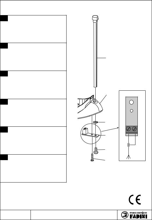
INSTALLAZIONE ANTENNA Birio A8 |
|
|
|
|
||
|
SUL LAMPEGGIATORE MIRI 4 |
|
|
|
|
||
|
1 |
- PUNTALE STELO |
|
|
|
|
|
|
2 |
- COLLARE LAMPEGGIATORE MIRI 4 |
|
|
|
|
|
|
3 |
- OR 2031 |
|
|
|
|
|
|
4 |
- SCHEDINA ANTENNA |
|
|
|
|
|
|
5 |
- VITE M5x10 T.C. |
|
|
|
|
|
|
6 |
- VITE AUTOFILETTANTE |
|
|
|
|
|
GB Birio A8 AERIAL FITTED TO THE |
|
|
|
|
|||
|
FLASHING LAMP MIRI 4 |
|
|
|
|
||
|
1 |
- AERIAL ROD |
|
|
|
|
|
|
2 |
- COLLAR OF FLASHING LAMP MIRI 4 |
|
|
1 |
|
|
|
3 |
- OR 2031 |
|
|
|
||
|
4 |
- AERIAL P.C. CARD |
|
|
|
|
|
|
5 |
- M5x10 T.C. SCREW |
|
|
|
|
|
|
6 |
- SELF-TAPPING SCREW |
|
|
|
|
|
F |
INSTALLATION ANTENNE Birio A8 SUR |
|
|
|
|
||
|
LA LAMPE DE SIGNALISATION MIRI 4 |
|
|
|
|
||
|
1 |
- TIGE |
|
|
|
|
|
|
2 |
- COLLIER LAMPE DE SIGNALISATION MIRI 4 |
|
|
|
||
|
3 |
- OR 2031 |
|
|
|
|
|
|
4 |
- CARTE ANTENNE |
|
|
2 |
|
|
|
5 |
- VIS M5X10 T.C. |
|
|
|
||
|
6 |
- VIS FILETEE |
|
|
|
|
|
D |
EINBAU DER Birio A8 ANTENNE AUF |
|
|
|
|
||
|
BLINKLEUCHTE MIRI 4 |
|
|
|
|
||
|
1 |
- STAB |
|
|
|
|
|
|
2 |
- SCHELLE BLINKLEUCHTE MIRI 4 |
|
|
|
|
|
|
3 |
- OR 2031 |
|
|
|
|
|
|
4 |
- ANTENNE PLATINE |
|
|
|
|
|
|
5 |
- SCHRAUBE M5x10 T.C. |
|
|
3 |
|
|
|
6 |
- SELBSTSCHNEIDENDE SCHRAUBE |
|
|
|
||
|
|
|
|
|
|||
E |
INSTALACION DE LA ANTENA Birio A8 |
|
|
|
|
||
|
EN EL DESTELLADOR MIRI 4 |
|
|
4 |
|
||
|
1 |
- VASTAGO |
|
|
GND. |
||
|
2 |
- COLLAR DESTELLADOR MIRI 4 |
|
|
ANT. |
||
|
3 |
- OR 2031 |
|
|
|
|
|
|
4 |
- FICHA ANTENA |
|
|
|
|
|
|
5 |
- TORNILLO M5x10 DE CABEZA CILINDRICA |
|
|
5 |
|
|
|
6 |
- TORNILLO AUTOENROSCANTE |
|
|
|
||
|
|
|
|
|
|||
NL INSTALLATIE Birio A8 ANTENNA OP DE |
|
|
6 |
|
|||
|
MIRI 4 BLINKER |
|
|
|
|||
|
1 |
- STEELPUNT |
|
|
|
|
|
|
2 |
- RAND MIRI 4 BLINKER |
|
|
|
|
|
|
3 |
- OR 2031 |
|
|
|
|
|
|
4 |
- ANTENNE KAART |
|
|
|
|
|
|
5 |
- CILINDERKOPSCHROEF M5x10 |
|
|
|
|
|
|
6 |
- ZELFTAPPENDE SCHROEF |
|
|
|
|
|
|
|
ViaMantova,177/A-C.P.126-37053Cerea(Verona)Italy-Tel.+390442330422r.a. |
® |
||||
Dis. N. 4036 Fax +39 0442 331054 |
- |
e-mail: info@fadini.net - |
www.fadini.net |
||||
|
|||||||

INSTALLATION MANUAL
GB |
FOR THE INSERTION OF THE CODE OF THE RADIO TRANSMITTER BIRIO 868 |
|
Made in Italy |

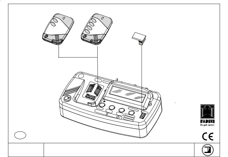
4 pushbutton
2 pushbutton transmitter transmitter
Birio |
Birio |
Birio
Birio 868
- ROLLING-CODE 868,35 MHz-
Removable
Memory
GB 4213
S |
|
UP |
|
9 V |
PLY |
|
OLT |
ON/OFF
Birio LC Device
to key-encode radio receivers and transmitters
Birio LC
GB
M |
|
|
|
|
EMO |
|
|
|
|
|
RY |
|
CO |
|
SELECT |
ENTER |
PY |
|
|
M |
|
|||
CO |
DE |
KEY |
EMO |
|
|
|
DELETE |
|
RY |
|
|
KEY |
REPLACE |
|
|
|
|
|
|
|
|
C |
DELETE |
|
|
|
OPYO |
|
|
|
|
|
NEBU |
|
|
|
|
TTON |
|
®
Made in Italy
Drwg. No. 4105
BIRIO 868 INSTRUCTIONS

CONTENTS |
|
|
CONTENTS .................................................................................................................................................................................... |
page |
2 |
INTRODUCTION............................................................................................................................................................................ |
page |
3 |
EXTERNAL RADIO RECEIVER ENCODING OPERATION ......................................................................................................... |
page |
4 |
PLUG-IN RADIO RECEIVER ENCODING OPERATION............................................................................................................. |
page |
5 |
RADIO RECEIVER FREE MEMORY READING ........................................................................................................................... |
page |
6 |
RADIO RECEIVER MEMORY DELETING .................................................................................................................................... |
page |
7 |
TRANSMITTER COPYING ON THE SAME RECEIVER ............................................................................................................. |
page |
8 |
RADIO TRANSMITTER CODE DELETING.................................................................................................................................. |
page |
9 |
BIRIO LC” DEVICE (KEY-READING) ........................................................................................................................................... |
page |
10 |
- “BIRIO LC” DEVICE.................................................................................................................................................................... |
page |
11 |
- “BIRIO LC” DEVICE TYPES ....................................................................................................................................................... |
page |
12 |
- “BIRIO LC” DEVICE OPERATING............................................................................................................................................. |
page |
13 |
- TRANSMITTER DATA READING ............................................................................................................................................. |
page 14 |
|
- TRANSMITTER KEY ENCODING.............................................................................................................................................. |
page 15 |
|
- TRANSMITTER KEY DELETING................................................................................................................................................ |
page 16 |
|
- TRANSMITTER COPY ................................................................................................................................................................ |
page 17 |
|
- TRANSMITTER REPLACING..................................................................................................................................................... |
page 18 |
|
- TRANSMITTER DELETING FROM THE RADIO RECEIVER ................................................................................................... |
page 19 |
|
- COPY ONE BUTTON (COMMON BUTTON)............................................................................................................................ |
page 20 |
|
- SELECT THE TRANSMITTER CODE......................................................................................................................................... |
page 21 |
|
- MEMORY DATA READING ....................................................................................................................................................... |
page 22 |
|
- MEMORY KEY ENCODYING...................................................................................................................................................... |
page 23 |
|
- MEMORY KEY DELETING.......................................................................................................................................................... |
page 24 |
|
- MEMORY COPYING ................................................................................................................................................................... |
page 25 |
|
- DIFFERENT INSTALLATIONS LEARNING .............................................................................................................................. |
page 27 |
|
- RADIO RECEIVER’S MULTIPLE LEARNING............................................................................................................................ |
page 28 |
|
“BIRIO TOOL” PC SOFTWARE INSTALLATION AND USE..................................................................................................... |
page 29 |
|
- “BIRIO TOOL” SOFTWARE OPENING..................................................................................................................................... |
page 30 |
|
- MEMORY DATA DOWNLOADING........................................................................................................................................... |
page 31 |
|
- TRANSMITTER DATA DOWNLOADING................................................................................................................................. |
page 32 |
|
- TRANSMITTER CODE SEARCH................................................................................................................................................ |
page 33 |
|
- TRANSMITTER COPYING ......................................................................................................................................................... |
page 34 |
|
- TRANSMITTER REPLACEMENT .............................................................................................................................................. |
page 35 |
|
- TRANSMITTER DELETING........................................................................................................................................................ |
page 36 |
|
- COPY ONE BUTTON (COMMON BUTTON)............................................................................................................................ |
page 37 |
|
- ADDING A TRANSMITTER TO THE MEMORY....................................................................................................................... |
page 38 |
|
DATA PRINTING........................................................................................................................................................................... |
page 39 |
|
BIRIO LC BATTERY RECHARGE.................................................................................................................................................. |
page 40 |
|
BIRIO 868, BIRIO LC SPECIFICATIONS ..................................................................................................................................... |
page |
41 |
DIMENSIONS................................................................................................................................................................................ |
page 42 |
|
2
INTRODUCTION
Birio 868 Radio Receiver and Transmitter use a self-learning Rolling-Code technology: every time a button is pressed and a signal is emitted, the transmitter code is changed at random by the system. Total security is so guaranteed.
Besides having the traditional Radio Transmitter and Receiver encoding procedure, Birio 868 both Transmitters and Receivers can be customized by the installer entering up to two “keys” (that is 216 numerical codes) by means of a Birio LC Device. This customizing operation is not functional but it responds to the needs for an exclusive product. The use of Birio LC device allows to create new transmitters with no need to operate directly on the installation.
|
|
|
|
|
Plug-in Radio Receiver |
Birio |
|
|
|
|
Birio 868 |
|
|
|
|
|
- ROLLING-CODE- |
2°R |
|
|
|
|
|
1°R |
|
|
|
|
|
|
|
|
3 |
2 |
1 |
|
|
4 |
|
||
|
5 |
|
|
||
|
|
|
|
||
|
|
|
|
|
AERIAL
Control Pannel
External Radio
Receiver
Birio |
Birio 868 |
|
- ROLLING-CODE- |
||
|
|
|
|
|
|
|
|
|
|
10 |
11 |
12 |
|
|
|
|
|
|
|
|
9 |
|
||
|
|
|
|
|
|
|
8 |
|
|
||
|
|
|
|
|
|
7 |
|
|
|
||
|
|
|
|
|
6 |
|
|
|
|
||
|
|
|
|
5 |
|
|
|
|
|
||
|
|
|
4 |
|
|
|
|
|
|
||
|
|
3 |
|
|
|
|
|
|
|
||
|
2 |
|
|
|
|
|
|
|
|
||
1 |
|
|
|
|
|
|
|
|
|
||
|
|
|
|
|
|
4th CHANNEL |
|
|
|||
|
1st CHANNEL |
2nd CHANNEL |
|
3rd CHANNEL |
|
|
|
||||
|
|
|
|
AERIAL |
|||||||
|
|
|
|
|
|
|
|
|
|
||
– +
24 VOLT a.c. POWER SUPPLY
External Radio |
Birio |
868 |
|
||
|
|
Receiver Case
3

EXTERNAL Birio 868 RADIO RECEIVER ENCODING OPERATION
POSSIBILE PIN COMBINATIONS |
|
PIN |
|
BUTTON “P” |
|
C4 |
C2 |
P2 |
REMOVABLEM |
||
4 |
2 |
|
|
|
EMORY |
|
|
|
|
||
|
Relay 1 - |
(C1) |
|
|
|
|
1st channel |
C1 |
P1 |
|
|
|
C3 |
|
|||
31
 “STRIP”
 JUMPER
4 |
2 |
|
|
Relay 2 - |
(C2) |
|
2nd channel |
|
|
|


 Birio
Birio
LED
3 1
4 |
2 |
|
R° |
1 |
|
|
R°2 |
|
|
|
|
|
|
|
|
Relay 3 - |
(C3) |
|
|
|
|
|
|
|
|
|
12 |
||
|
3rd channel |
|
|
|
|
|
|
|
|
|
|
11 |
||
|
|
|
|
|
|
|
|
|
|
9 |
10 |
|||
3 |
|
|
|
|
|
|
|
|
|
|
||||
1 |
|
|
|
|
|
|
|
|
8 |
|
|
|||
|
|
|
|
|
|
|
7 |
|
|
|
||||
|
|
|
|
|
|
6 |
|
|
|
|
||||
|
|
|
|
|
|
|
5 |
|
|
|
|
|
||
|
|
|
|
|
|
4 |
|
|
|
|
|
|
||
|
|
|
|
|
3 |
|
|
|
|
|
|
|
||
|
|
|
|
2 |
|
|
|
|
|
|
|
|
||
|
|
|
1 |
|
|
|
|
|
|
|
|
|
||
|
|
|
|
|
|
|
|
|
4th CHANNEL |
|
|
|||
4 |
2 |
|
|
1st CHANNEL |
|
2nd CHANNEL |
|
3rd CHANNEL |
|
|
|
|||
|
RELAY |
|
|
|
|
AERIAL |
||||||||
|
Relay 4 - |
(C4) |
1st CHANNEL |
|
|
|
|
|
|
|
|
|
||
|
|
|
|
|
|
|
|
|
|
|
|
|||
|
4th channel |
– + |
|
|
|
|
|
|
|
|
|
|
||
|
|
|
|
|
|
|
|
|
|
|
|
|||
3 |
1 |
|
24 VOLT a.c. |
|
|
|
|
|
|
|
|
|
|
|
POWER SUPPLY
R°4
RELAY
R°3
RELAY
PUSH BUTTON
LED
Birio
2 pushbuttons Birio
PUSH BUTTON
LED
Birio
4 pushbuttons Birio
SHOULD 24 V a.c. – 13 Vc.c. BE INTERRUPTED, THE CODE IS KEPT IN THE REMOVABLE MEMORY AND IT IS POSSILE TO INSERT IT INTO ANOTHER PC CARD.
1)Insert the removable Memory and supply the External Radio Receiver by connecting terminals 1(-) and 2 (+) to 24 V a.c. carry out connections of the N.O: contact to activate the required channel.
2)Insert the “Strip” jumper into C1 position stimulating the 1R: relay corresponding to 3 and 4 terminals (1st Channel)
3)Press simultaneously P pushbutton on the Radio and any pushbutton on the transmitter you intend to operate as 1st Channel, for about 5 seconds. As storing confirmation the red led will illuminate. Release the push button P and the push button on the transmitter.
4)Remove the “Strip” jumper and plug it into only one PIN.
5)For 2nd, 3rd and 4th channel storing, operate as above and plug the “Strip” jumper into the respective PINS (see picture) and the relays into the respective connectors corresponding to the required channel.
4
PLUG-IN Birio 868 RADIO RECEIVER ENCODING OPERATION
POSSIBLE PIN COMBINATIONS |
|
PIN |
|
|
|
||
|
|
C2 |
|
2 |
|
P2 |
|
Relay 1 - |
(C1) |
P1 |
|
|
|||
1st channel |
C1 |
||
|
REMOVABLEME |
PUSH |
MORY |
BUTTON “P” |
1
|
“STRIP” |
|
|
|
|
|
|
|
|
|
|
JUMPER |
|
|
|
Birio |
|
|
|
|
|
|
|
|
|
|
|
|
|
|
|
|
2 |
|
|
|
|
|
|
|
|
|
LED |
Relay 2 - |
|
|
|
R° |
2 |
|
|
|
|
|
|
(C2) |
R° |
1 |
|
|
|
|
|||
|
|
|
|
|
|
|||||
|
2nd channel |
|
|
|
|
|
|
|||
|
|
|
|
|
|
|
|
|
||
1 |
|
RELAY |
|
|
|
|
|
|
2 |
1 |
|
|
1st CHANNEL |
|
|
+ |
|
|
3 |
|
|
|
|
|
|
|
– |
5 |
4 |
|
|
|
|
|
|
|
|
|
|
|
|||
|
|
|
|
|
|
|
|
|
||
|
|
|
|
|
|
|
|
|
|
|
|
|
RELAY |
|
|
|
|
|
|
|
|
|
|
2nd CHANNEL |
|
|
|
|
|
|
|
AERIAL |
|
|
|
|
|
|
|
|
|
|
|
|
|
TO FIT INTO CONTROL |
|
|
2nd CHANNEL N.O. |
|||||
|
|
PANNEL |
|
|
|
|
OR N.C. CONTACTS |
|||
PUSH BUTTON
LED
Birio
2 pushbuttons Birio
PUSH BUTTON
LED
Birio
4 pushbuttons Birio
SHOULD 24 V AC – 13 V CC BE INTERRUPTED, THE CODE IS KEPT IN THE REMOVABLE MEMORY AND IT IS POSSILE TO INSERT IT INTO ANOTHER PC CARD.
1)Insert the removable Memory and supply the Plug-in Radio Receiver by plugging it into the control panel.
2)Insert the “Strip” jumper into C1 position stimulating the 1R: this corresponds to 3 and 4 terminals (1st Channel)
3)Press simultaneously P pushbutton on the Radio and any pushbutton on the transmitter you intend to operate as 1st Channel, for about 5 seconds. As storing confirmation the red led will illuminate. Release the push button P and the push button on the transmitter.
4)Remove the “Strip” jumper and plug it into only one PIN.
5)For 2nd channel storing, operate as above and plug the “Strip” jumper into C2 (stimulating the 2R relay); connect the 2nd channel (NO or NC) then push the button on the transmitter.
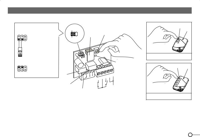
5
RADIO RECEIVER MEMORY READING
PLUG-IN RADIO RECEIVER
2
PIN |
P1 |
(FREE MEMORY) |
|
1 |
|||
|
|
||
|
|
PUSH BUTTON “P” |
|
“STRIP” |
|
REMOVABLE |
|
JUMPER |
|
MEMORY |
|
Birio |
|
|
|
|
LED |
|
|
|
|
|
|
|
R°1 |
R°2 |
|
|
|
|
|
|
|
|
|
|
|
|
|
– + |
|
|
3 |
2 |
1 |
|
|
4 |
|
|||
|
5 |
|
|
|||
|
|
|
|
|
|
AERIAL
TO FIT INTO
CONTROL PANEL
EXTERNAL RADIO RECEIVER
42 PIN
3 |
1 |
P1 |
(FREE MEMORY) |
|
|
|
|
|||||
|
|
|
|
|
|
|
|
|
|
|
||
|
|
“STRIP” |
|
|
PUSH BUTTON “P” |
|||||||
|
|
|
|
|
|
|
|
|
|
|||
|
|
JUMPER |
|
|
|
|
|
|
|
|
||
|
|
|
REMOVABLE |
|
|
|
|
|
|
|||
|
|
|
MEMORY |
|
|
|
|
|
|
|
||
|
|
|
|
|
Birio |
|
|
|
|
|
|
|
|
R°1 |
|
|
R°2 |
|
|
|
|
|
|
||
|
|
|
|
|
|
|
|
|
11 |
12 |
||
|
|
|
|
|
|
|
|
|
|
10 |
||
|
|
|
|
|
|
|
|
|
9 |
|
||
|
|
|
|
|
|
|
|
8 |
|
|
||
|
|
|
|
|
|
|
7 |
|
|
|
||
|
|
|
|
|
|
6 |
|
|
|
|
||
|
|
|
|
|
5 |
|
|
|
|
|
||
|
|
|
|
4 |
|
|
|
|
|
|
||
|
|
|
3 |
|
|
|
|
|
|
|
||
|
|
2 |
|
|
|
|
|
|
|
|
||
|
1 |
|
|
|
|
|
4th CHANNEL |
|
|
|||
|
|
|
|
|
|
|
|
|
||||
|
|
1st |
CHANNEL |
2nd CHANNEL |
|
3rd CHANNEL |
|
|
|
|||
|
|
|
|
|
|
|
||||||
AERIAL
– +
24 VOLT a.c. POWER SUPPLY
LED
1)Insert the removable Memory and supply the External Radio Receiver with 24 V a.c. by terminals 1(-) and 2 (+) ; plug the Radio Receiver into the control panel.
2)Insert the “Strip” jumper into P1 position -free memory reading-.
3)Press P pushbutton on the Radio Receiver for about 5 seconds. Release the push button P and the red led will flash: every flash corresponds to 180 transmitters to store, for ex: 7 flashes mean 7x180=1˙260 trasmitters still to store, (180 transmitters multipied by 10 flashes is 1˙800 transmitters to store).
4)Remove the “Strip” jumper and plug it into only one PIN.
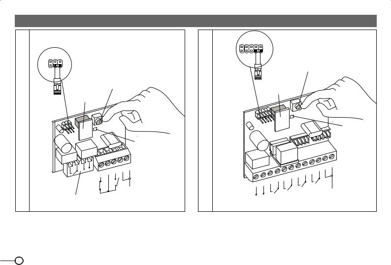
6

RADIO RECEIVER MEMORY DELETING
PLUG-IN RADIO RECEIVER
“STRIP” JUMPER
2
PIN P2 (TOTAL MEMORY DELETION)
1
PUSH BUTTON “P”
REMOVABLE
MEMORY
|
Birio |
|
|
|
|
|
|
|
|
|
|
|
LED |
R°1 |
R°2 |
|
|
|
|
|
|
|
|
|
|
|
|
|
+ |
|
|
3 |
2 |
1 |
|
|
|
|
|||
|
– |
5 |
4 |
|
|
|
|
|
|
|
|||
|
|
|
|
|
||
|
|
|
|
|
|
AERIAL
TO FIT INTO
CONTROL PANEL
EXTERNAL RADIO RECEIVER
“STRIP” JUMPER
PIN
42
P2 (TOTAL MEMORY DELETION)
31
PUSH BUTTON “P”
REMOVABLE
MEMORY
Birio
R°1 |
|
|
R°2 |
|
|
|
|
|
|
||
|
|
|
|
|
|
|
|
11 |
12 |
||
|
|
|
|
|
|
|
|
|
10 |
||
|
|
|
|
|
|
|
|
9 |
|
||
|
|
|
|
|
|
|
8 |
|
|
||
|
|
|
|
|
|
7 |
|
|
|
||
|
|
|
|
|
6 |
|
|
|
|
||
|
|
|
|
5 |
|
|
|
|
|
||
|
|
|
4 |
|
|
|
|
|
|
||
|
|
3 |
|
|
|
|
|
|
|
||
|
2 |
|
|
|
|
|
|
|
|
||
|
|
|
|
|
|
4thCHANNEL |
|
|
|
||
|
CHANNEL1st |
|
CHANNEL2nd |
|
CHANNEL3rd |
|
|
|
|
||
POWER SUPPLY |
|
|
|
|
|
|
|||||
1 |
|
|
|
|
|
|
|
|
|
|
|
|
|
|
|
|
|
|
|
|
|
AERIAL |
|
– + |
|
|
|
|
|
|
|
|
|
|
|
24 VOLT a.c. |
|
|
|
|
|
|
|
|
|
|
|
LED
1)Insert the removable Memory and supply the External Radio Receiver with 24 V a.c. by terminals 1(-) and 2 (+) ; and plug the Radio Receiver into control panel.
2)Insert the “Strip” jumper into P2 position.
3)Press P pushbutton on the Radio Receiver for about 5 seconds. Release the push button P and the red led will illuminate: memory deleted.
4)Remove the “Strip” jumper and plug it into only one PIN.
7

TRANSMITTER COPYING ON THE SAME RECEIVER
IMPORTANT: Transmitter copying is possible even if keys are encoded (see chapter about Birio LC device) provided that they were encoded by the same Birio LC encoding device.
Birio 2 buttons
|
New |
Push 1st button |
A |
and release |
|
when the led |
|
turns off
1st Operation
Operations to be carried out in 30 seconds max time
New
Push 2nd button and |
A |
Push 1st button |
B |
|
and release when |
||
release when the led |
|
||
|
the led turns off |
|
|
turns off plus 2 seconds |
|
|
|
|
|
|
|
|
2nd Operation |
|
3rd Operation |
Push 2nd button B and release when
the led turns off
4th Operation
Birio |
|
|
|
|
R°2 |
|
|
|
|
R°1 |
|
|
|
|
|
|
3 |
2 |
1 |
5 |
4 |
|
|
|
|
|
|
||
|
|
|
|
|
|
|
|
AERIAL |
|
PLUG-IN RECEIVER
Birio 4 buttons
New
Push 1st button
and release A when the led
turns off
1st Operation
Operations to be carried out in 30 seconds max time
New
A
Push 2ndt button and release when the led turns off plus 2 seconds
2nd Operation
Push 1st button and |
B |
release when the |
|
led turns off |
|
3rd Operation
Push 2nd button B and release when
the led turns off
4th Operation
|
|
|
Birio |
|
|
|
|
|
|
|
|
|
|
|
|
|
|
|
9 |
10 |
11 12 |
|
|
|
|
|
6 |
7 |
8 |
|
|
|
|
|
|
|
5 |
|
|
|
|
||
|
2 |
3 |
4 |
|
|
|
|
|
|
|
1 |
|
|
|
|
|
4th CHANNEL |
|
|||
|
1st CHANNEL |
|
2nd CHANNEL |
|
3rd CHANNEL |
|
|
|||
POWER SUPPLY |
|
|
|
AERIAL |
||||||
– +
24 VOLT a.c.
EXTERNAL RECEIVER
TO COPY NEW TRANSMITTERS OPERATING ON THE SAME RADIO RECEIVER, YOU NEED TO HAVE AN ENCODED TRANSMITTER AND TO CARRY OUT TWO OPERATIONS SEQUENCELY. THESE OPERATIONS MUST BE EFFECTED AT A MAX DISTANCE OF 10 METRES FROM THE RADIO RECEIVER, DULY POWER SUPPLIED, AERIAL CONNECTED.
1st Operation: Push the 1st button on the new Radio Transmitter A and release when the Led turns off.
2nd Operation: Push the 2nd button on the new Radio Transmitter A as long as the Led turns off plus 2 seconds. Then release the button. 3rd Operation: Push the1st button on the encoded Radio Transmitter B and release when the Led turns off.
4th Operation: Push the 2nd button on the encoded Radio Transmitter B and release when the Led turns off. Repeat these operations for any new Transmitter required.
8

RADIO TRANSMITTER CODE DELETING
IMPORTANT: Transmitter deleting is possible even if keys are encoded (see chapter about Birio LC device) provided that they were encoded by the same Birio LC encoding device.
Birio 2 buttons
Push 2ndt button and release when the led turns off
Birio
Push 1st button and release when the led turns off
Birio
Push 2nd button and release when the led turns off
Birio
Push 1st button and release when the led turns off
Birio
Push 2nd button and release when the led turns off
Birio
Push 1st button and release when the led turns off
Birio
1st Operation |
2nd Operation |
3rd Operation |
4th Operation |
5th Operation |
6th Operation |
Birio 4 buttons
Push 2nd button and release |
Push 1st button and release |
Push 2nd button and release |
Push 1st button and release |
Push 2nd button and release |
Push 1st button and release |
||||||
when the led turns off |
|
when the led turns off |
|
when the led turns off |
|
when the led turns off |
|
when the led turns off |
|
when the led turns off |
|
B |
irio |
B |
irio |
B |
irio |
B |
irio |
B |
irio |
B |
irio |
|
|
|
|
|
|||||||
1st Operation |
|
2nd Operation |
|
3rd Operation |
|
4th Operation |
|
5th Operation |
|
6th Operation |
|
IF YOU NEED TO DELETE A TRANSMITTER CODE OPERATE AT A MAX DISTANCE OF 10 METRES FROM THE RADIO RECEIVER, DULY POWER SUPPLIED, AERIAL CONNECTED.
Insert the removable “Strip” jumper on P1 position on the Radio Receiver:
1st Operation: Push the 2nd button on the Radio Transmitter and release when the Led turns off 2nd Operation: Push the 1st button on the new Radio Transmitter and release when the Led turns off Repeat these 2 Operations for 6 times and end the sequence pushing the 1st button. Then Insert the
“Strip” jumper in only one PIN.
Repeat these operations for every transmitter you wish to delete.
N.B: IF THE NUMBER OF OPERATIONS OR THE TIME BEFORE NEXT PRESSING ARE MISTAKEN, YOU MUST REPEAT THE OPERATIONS FROM THE BEGINNING, AND WAIT 1 MINUTE BEFORE STARTING AGAIN.
2
PIN P1 1
P1 1
REMOVABLE “STRIP” MEMORY JUMPER
Birio |
LED |
|
|
R°2 |
|
R°1 |
|
Relay |
|
Relay |
|
PLUG-IN RADIO RECEIVER
42
PIN 


 P1 3 1
“STRIP”
JUMPER
REMOVABLE MEMORY
Birio |
LED |
|
|
Relay |
|
EXTERNAL RADIO RECEIVER
9
 Loading...