


Elpro 23
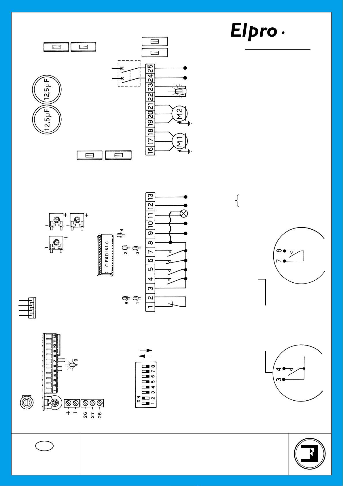
CONNECTION DIAGRAM
ELECTRONIC PROGRAMMER
FOR SINGLE-PHASE SWING GATES
GB
Drwg. No.
2125
1 A FUSE
FUSE
630 mA
2 AMP. FUSE TO PROTECT
THE ELECTRIC LOCK
OUTPUT
TERMINALS
No. 9-10
240 V SINGLE-PHASE
SUPPLY VOLTAGE
240 V - 25 W max. FLASHING LAMP
SINGLE-PHASE
ELECTRIC MOTORS
24 V OUTPUT A.C.
N.C. CONTACT
PHOTOCELLS
OPEN SWITCH N.O. CONTACT
CLOSE SWITCH N.O. CONTACT
STOP SWITCH N.C. CONTACT
RADIO CONTACT N.O.
VOLTAGE OUTPUT
ELECTRIC LOCK SUPPLY 12V A.C./ 24V D.C.
24 V INDICATOR GATE OPEN - 3 W max.
Max permitted load:
2 pairs photocells
1 radio receiver
COMMON
Should more pairs of photocells be required than
the recommended quantity, fit an auxiliary
transformer outside the control box.
NOTE WELL: For special applications, ie. to switch
on lights - CCTV etc., SOLID STATE RELAYS are
recommended to be used only. Standard relays
would affect the micro-processor.
NOTE WELL: THIS PANEL IS TESTED TO
OPERATE GATES ONLY THROUGH FADINI
ACCESSORIES. NO GUARANTEE FOR
ACCESSORIES OF OTHER MAKE OR SPECIAL
APPLICATIONS.
ALL OPERATIONS
OPEN, CLOSE AND
REVERSE
RADIO CONTACT
ON
OFF
RADIO CONTROL
PLUG-IN CARD SUPPORT
DIP-SWITCH
TERMINALS FOR THE
CONNECTIONS TO THE
PUSH BUTTONS PULIN 3
1
st
CHANNEL
24 V OUTPUT
MICROPROCESSOR
LEAF DELAY
TIMER CLOSE
DWELL TIME
bpt
FOR SWING GATES
23
CEI
OUTPUT
24 V. D.C.
MOTOR RUN TIME
OPEN & CLOSE
PULSE TWICE
CONSECUTIVELY TO OPEN
BOTH GATE LEAFS
FUSE
630 mA
5 AMP .
FUSE
CAPACITORS
CUT OFF SWITCH
BY COVER KNOB
COMMON
PEDESTRIAN MODE
ONE PULSE OPENS
ONE GATE LEAF ONLY
COMMON
COMMON
1 A FUSE TO PROTECT
THE 24 V= OUTPUT

®
bpt
23
CEI
FEATURES OF THE ELECTRONIC PROGRAMMER FOR SWINGING GATES
All the electrical connections are to be made as per the following instructions and diagrams. Supply the terminals 24-25 with 240V- 50 Hz
single-phase voltage. The “Red LED” switches on and stays on as long as the board is properly supplied. Through the timer No. 9 you
can control the running time of the motor in both cycles, OPEN and CLOSE. Set it so that the running time of the motor is longer than the
actual travel of the gate; set the timer No. 8 - DWELL - ie. the interval between open and re-closing, so that you can meet the required
interval of time. The timer No. 7 - LEAF DELAY in "close" cycle - is to be set as follows: on to "-" (less) the delay is out of service; clockwise
on to "+" (more) the delay is operative.
- With the electric motor connected to terminals 19-20-21: the delay is operative in the "open" cycle, with a factory pre-set time.
- With the electric motor connected to 16-17-18: the delay is operative in "close" cycle and can be adjusted through the timer No. 7 on to
"less" or "more".
LOGIC OF THE ELECTRONIC PROGRAMMER: When a pulse is given, the flashing light switches on. After three seconds the motors start .
During the interval before re-closing, the light stays on. When the gates are fully re-closed, the light keeps on flashing for three more seconds
and then switches off automatically.
The 3 second interval (pre-flashing) which precedes the actual start of the motors can be eliminated by means of the DIP-SWITCH “A” No. 4.
LED No. 1: "OPEN". It switches on when the respective switch is activated.
LED No. 2: "CLOSE". It switches on when the respective switch is activated.
LED No. 3: "RADIO". It switches on whenever a pulse is given, either from remote control, keyswitch or push buttons.
LED No. 4: “STOP". Normally on. It switches off when the respective switch is activated.
LED No. 8: "PHOTOCELLS". Normally on. It switches off when the photocells are obstructed.
LED No. 9: It switches on when voltage is supplied.
DIP-SWITCH SETTING IN ELPRO 23 type "A"
N° 1 OFF = PHOTOCELLS. NO STOP IN OPEN CYCLE. REVERSE/CLOSE
N° 2 OFF = REMOTE CONTROL. REVERSE
N° 3 OFF = NO AUTOMATIC RECLOSING
N° 4 OFF = NO PRE-FLASHING
N° 5 OFF = REMOTE CONTROL. NO STOP AND HOLD AS LONG
AS BUTTON DOWN. IT OPENS STRAIGHT AWAY
N° 6 OFF = BOTH LEAFS ARE OPERATED
N° 7 OFF = S. R. P. OUT OF SERVICE
N° 8 OFF = LEAF DELAY OPEN CYCLE.
ONE STARTS BEFORE THE OTHER
LAMP ON = GATE OPEN
LAMP FLASHES SLOWLY = GATE OPENING
LAMP FLASHES FAST = GATE CLOSING
LAMP OFF = GATE CLOSED
1) It is advisable not to expose the control box directly to weather conditions; if mounted outside, a suitable enclosure is recommended to
protect it from sunshine and rain.
2) Bridge terminals 1 - 2 if you do not require any photocells.
3) Should two sets of photocells be required, these are to be series connected to terminals 1 - 2, contact normally closed.
4) Bridge terminals 6 - 8 if you do not require any keyswitch or push buttons.
5) Fit the mains to the control box with a high sensitivity, differential, magnetic-thermal switch, 0.03 Amps.
6) NOTE WELL
FAULT FINDING:
- Check supply voltage with a tester: it must be 240V, single-phase
- Check the high voltage fuses
- Check if the photocells contacts are normally closed
- Check voltage from the control box to the electric motor(s): power might have dropped
- Check the low voltage fuse
- The section of the electric cables to the motor(s) must not be less than 1.5 mm
2
* 24 V ~ output. Terminals 12-13. It can supply power for 2 pairs of photocells plus 1 radio receiver. Terminal 11 provides a power output
for a lamp. 24 V - 3 W max. Flashing lamp output. Terminals 22-23. Maximum available power 25 W max.
N° 1 ON = STOP DURING OPEN CYCLE
N° 2 ON = NO REVERSE DURING OPEN CYCLE
N° 3 ON = AUTOMATIC RECLOSING
N° 4 ON = PRE-FLASHING
N° 5 ON = STOP AND HOLD AS LONG AS
THE BUTTON IS KEPT DOWN
N° 6 ON = PEDESTRIAN. ONE LEAF ONLY
GATES IN CLOSE POSITION
N° 7 ON = S. R. P. IN SERVICE
GATES IN CLOSE POSITION
N° 8 ON = NO LEAF DELAY
BOTH MOTORS START TOGETHER
 Loading...