

Page 1

MEC 200
Electro-mechanical sliding gate operator
Vertical and horizontal installation
Gear movements and worm-gear coupling
in oil bath fully mounted on ball bearings
Installation manual
GB
Page 2
INSTRUCTIONS TO FIT THE VERTICAL AND HORIZONTAL MEC 200
OPERATORS TO A SLIDING GATE
FOR A PROPER AND PERFECT PERFORMANCE OF MEC 200 READ THE INSTRUCTIONS THAT ARE OUTLINED IN THIS MANUAL AND
KEEP TO THE DIAGRAMS.
Mec 200 is an extremely versatile system and can suit any sliding gate as it can be mounted either vertically or horizontally, and the motor
is available in different power specifications such as 0.37 KW (0.5 HP single- and three-phase); 0.73 KW (1.0 HP single- and three-phase);
1.1 KW (1.5 HP three-phase only). It is a strong and reliable automation. It has a torque control device that can be manually adjusted;
worm and gear are made of bronze and steel and are supported by bearings, in an oil bath. A manual overriding system allows manual
operations of the gate in emergency events like power failure.
POINTS TO CHECK WITH THE GATE
- Check that the gate track is well fixed to a solid foundation to prevent deformation which would result into an unbalanced travelling of
the gate.
- IMPORTANT: Make sure that gate stops are fixed in the open and closed gate positions so that the gate does not over travel the permitted
limit and go out of the upper guide.
- IMPORTANT: Make sure that, once at the end of the permitted travel, the gate does not hit the gate posts or special gate stops to avoid
damages to its structure.
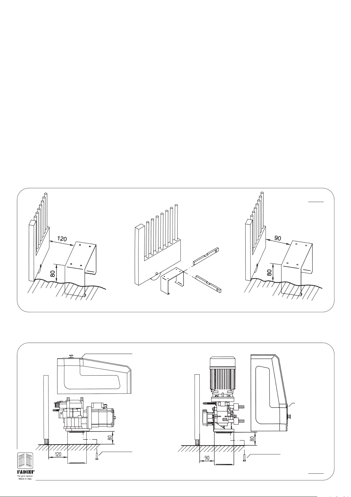
FITTING MEC 200 ON TO THE FIXING BASE PLATE
- The first operation is to fix the fixing base plate to the ground and make sure that it is perfectly levelled. Fixing distances are as indicated
in pic.1 here below. Fixing is by setting the plate into a concrete foundation.
- Remove the MEC 200 cover by loosening the three screws-A and pulling it upwards; Temporary fix the MEC 200 operator to the fixing
base plate by means of the four screws-B. (pic. 2).
PIC. 1
FIXING
FIXING BASE PLATE
TO SET IN CONCRETE
SPIRIT LEVEL
GROUND
MEC 200 HORIZONTAL
GROUND
MEC 200 VERTICAL
- Remove the MEC 200 cover by loosening the three screws-A and pulling it upwards; temporary fix the MEC 200 operator to the fixing
base plate by means of the four screws-B (pic.2).
SCREWS TO FIX
THE COVER - A
BASE PLATE
TO SET IN
CONCRETE
PROTECTION
COVER
PROTECTION COVER
SCREWS TO FIX
THE COVER - A
MEC 200 HORIZONTAL
4 Nos. FIXING
SCREWS - B
MEC 200 VERTICAL
4 Nos. FIXING
SCREWS - B
PIC. 2
2
Page 3
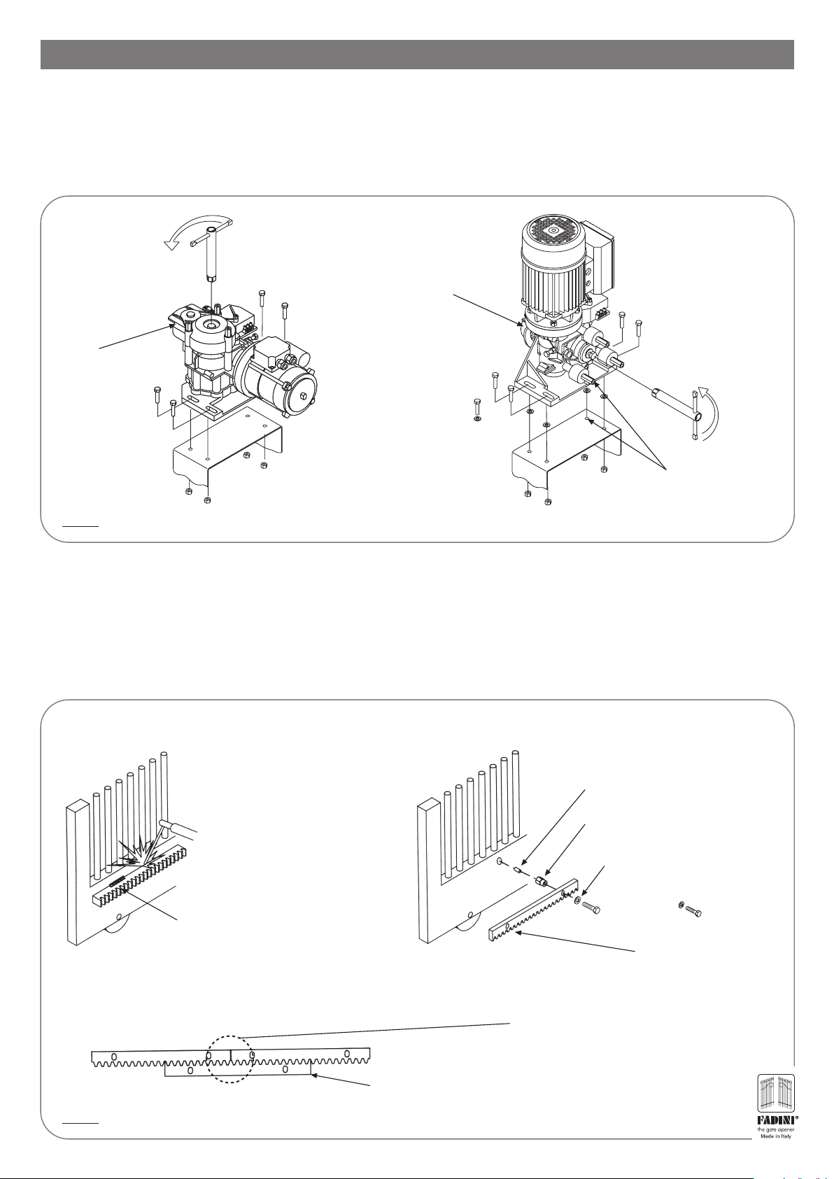
RACK FITTING OPERATIONS
IMPORTANT: If installing MEC 200 Vertical it is recommended to insert 2 mm shims between the fixing bracket and the operator base
plate before welding the rack to the gate, so that rack and gear mesh each other with an adequate clearance after that the shims have
been removed.
- Temporary fix MEC 200 on to the fixing bracket, perfectly levelled, by means of the 4 fixing screws C.
- MEC 200 outer gear must run idle: loosen (by 1 or 2 turns maximum) the hexagonal head screw by means of the release spanner E 17
supplied with the equipment (pic.3).
RELEASE SPANNER E 17
ANTI-CLOCKWISE
TO RELEASE
M8 FIXING
SCREWS - C
DRIVING GEAR
OR SPROCKET
DRIVING GEAR
OR SPROCKET
PIC. 3
FIXING
BRACKET
M8 FIXING
SCREWS - C
FIXING
BRACKET
MEC 200 HORIZONTAL MEC 200 VERTICAL
ANTI-CLOCKWISE
TO RELEASE
RELEASE
SPANNER E 17
2 mm SHIMS TO
REMOVE AFTER HAVING
FIXED THE RACK TO
THE GATE
- While fixing the rack it is required that the MEC 200 driving gear is not connected with the gate and it can be made run idle by means
of the release spanner E17 supplied with the equipment; the gate can be freely moved by hand.
- Temporary clamp the rack to the gate so that it can adequately mesh the driving gear: the rack must mesh the driving gear, idle, of MEC
200 in a very smooth way, without friction (pic. 4).
IMPORTANT: Before definitely fixing any component, make sure that the rack can mesh the driving gear of MEC 200 so that the whole
system, gate included, can be smoothly run by hand the full travel open and close without any friction.
- Remove the 2 mm shims only after having fixed the rack. An adequete clearance between rack and gear has thus been achieved (pic. 4).
RACK FIXING BY WELDING IT TO THE GATE RACK FIXING BY MEANS OF SCREWS AND FITTING PARTS
PIC. 4
22x22 mm RACK, 2 m LENGTH
RIGID SPOT WELDING
MEC 200 HORIZONTAL MEC 200 VERTICAL
IMPORTANT: respect the same rack pitch when joining
the rack bars. Use a spare rack bar as in the picture to
make sure that the junction has the same configuration.
PITCH GAUGING SPARE RACK
M8 SCREW
THREADED PIN
DISTANCE NUT
WASHER
MEC 200 VERTICAL IS SUPPLIED
WITH 8 mm STEEL RACK, 1 m
LENGTH TO BE FIXED BY SCREWS
3
Page 4
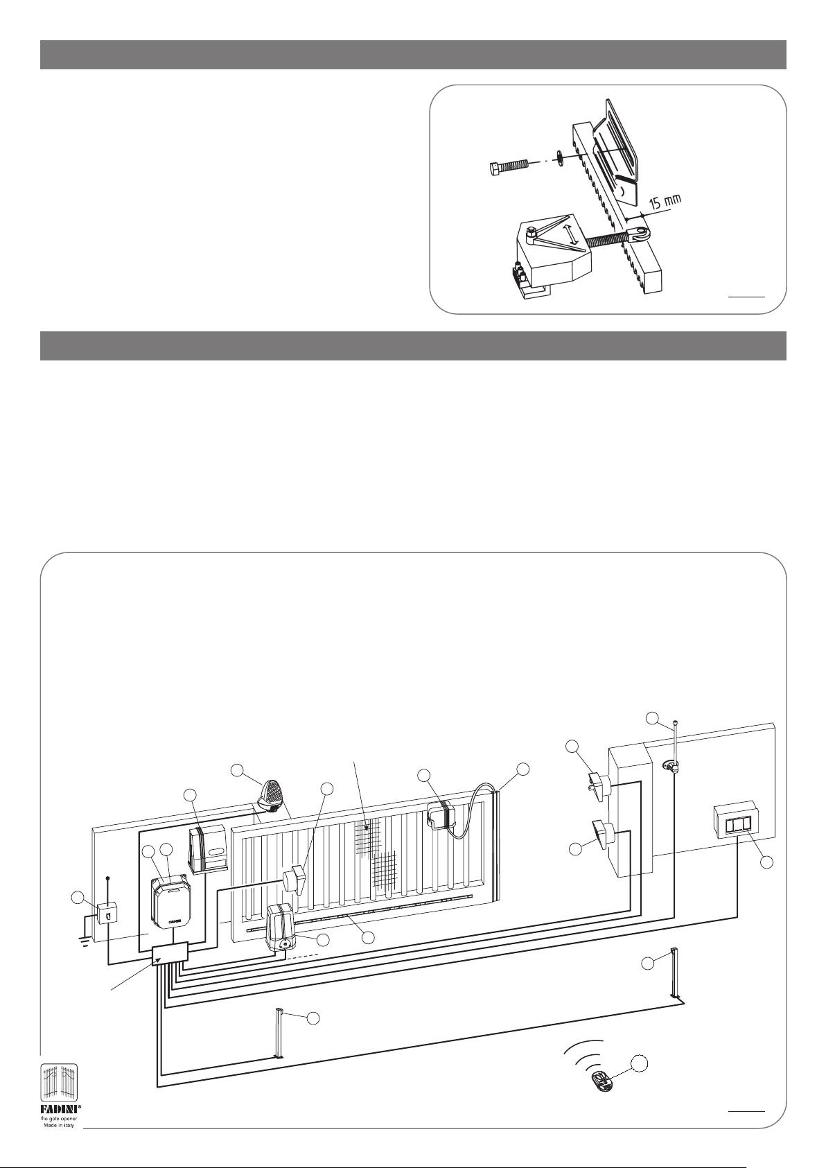
LIMIT SWITCH FITTING INSTRUCTIONS
- Fix the limit switch striking plates as shown in the diagram: the
distance between the roller tip of the limit switch spring and the
striking plate front surface line must be 15 mm. This distance
LIMIT SWITCH STRIKING
PLATE TO BE FIXED TO THE
GATE BY BOLTS
will allow the correct operation of the limit switch spring in both
travelling directions (pic. 5). Should the limit switch roller go
beyond the 15 mm distance, unscrew and remove the roller, then
cut the spring to measure.
- IMPORTANT: The gate must stop before hitting the gate post or
LIMIT SWITCH ROLLER
special gate stops to prevent any damage to its structure.
PIC. 5
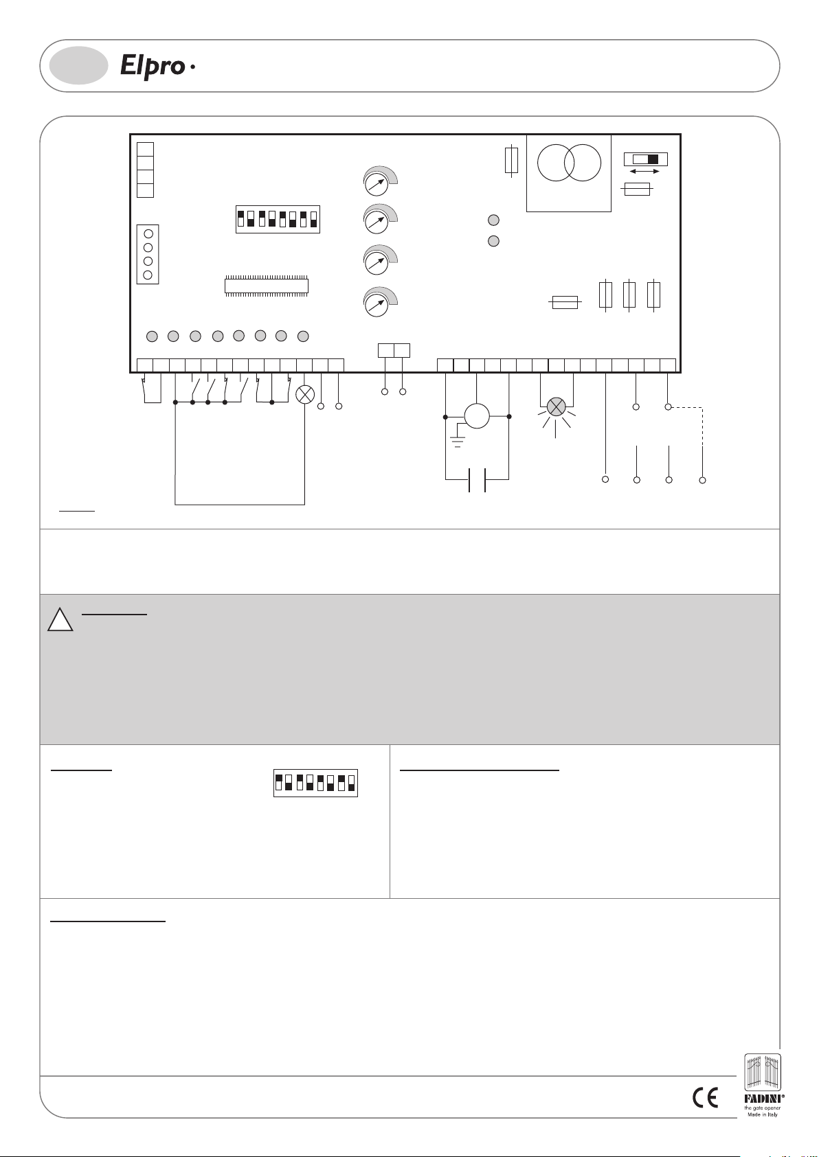
ELECTRICAL CONNECTIONS TO THE ELECTRONIC CONTROL PANEL
- Voltage supply, electric motor, flashing lamp Miri 4 require 1.5 mm2 cables, which must not exceed a 50 m distance. For greater distances
the recommended cable square section is 2 mm2 (pic. 6).
- Limit switches, photocells, keyswitch, push button switch and accessories: 1 mm2 cables can be used for these items (Pic.6).
- The safety pneumatic edge is to be fitted to the gate edge and is connected to the control box by a cable to be automatically rewound
to take up the slack. A remote controlled switch can be fitted instead, series connected with the limit switch or the photocell receiver.
- The electronic control panels type ELPRO 10 PLUS (pic.7) and ELPRO 14 PLUS (for double bi-parting sliding gates only) are pre-set for
all required operations, automatic or semi-automatic, and are fitted with line relays and fault-detecting led indicators.
- The electronic control panel type ELPRO 70/3 PLUS is incorporated in the operator and wiring is to be done as indicated in the diagram (pic.8).
N.W. CARRY OUT AN ANALYSIS OF THE RISKS INVOLVED IN COMPLIANCE WITH THE EN 12445 AND EN 12463 NORMS. PROVIDE SAFETY
DEVICES WHERE NEEDED.
1) Flashing lamp MIRI 4
2) Photocell receiver POLO 44
3) Radio link receiver CRUASTRO
4) Electronic Programmer ELPRO 10 PLUS
5) Magnetic Thermal 0.03 A, 230 V 50 Hz Mains Circuit Breaker
(beyond 100 m cable Ø 2.5 mm)
6) Gate operator MEC 200
7) Gear rack
8) Radio Link transmitter CRUASTRO
FIT THE GATE WITH A METALLIC NET
IN CASE THE GATE OPENINGS ARE
WIDER THAN 8 mm
1
n°3x1
2
6
7
3
4
11
230 V
n°2x1
5
n°4x1,5
n°2x1
n°4x1
n°3x1,5
9) Pneumatic Safety Edge or Sensor Barrier
10) Keyswitch PRIT 19
11) Plug-in Radio Receiver Card ASTRO 43/2R
12) Aerial BIRIO A8
13) Photocell Receiver POLO 44
14) Push Buttons PULIN 3
15) Post with POLO 44 Photocell Receiver
16) Post with POLO 44 Photocell Projector
17) Transmitter ASTRO 43/2 TR Piccolo/Small
12
10
8
9
n°4x1
13
n°2x1
16
cable RG58
14
n°4x1
JUNCTION BOX
WHERE ALL CABLES
ARE PRE-TERMINATED
4
15
n°2x1
IMPORTANT: All the electrical equipment to be properly earthed.
n°4x1
17
PIC. 6
Page 5
GB
10
PLUS
SINGLE- AND THREE-PHASE FOR SLIDING GATES
AND AUTOMATIONS FITTED WITH LIMIT SWITCHES
PIC. 7
26
27
PULIN 3
28
3
RADIO
PLUG-IN
CARD CONNECTOR
L3
L2
1
2
3
SAFETY EDGE
PHOTOCELLS
L4
COMMON
OPEN
DIP-SWITCH
2
1
3
ELPRO 10 plus 1.5
MICROPROCESSOR
L5
L8
L9
74
85
RADIO
STOP
LIMIT SWITCH CLOSE
CLOSE
ON
OFF
6
8
4
7
5
L6
L7
96
10
COMMON LIMIT SWITCH
LIMIT SWITCH OPEN
13
11
12
24V max 3W pilot light
1 radio receiver
2 pairs photocells
24V OUTPUT max. load:
-
-
-
-
T4
EXT TIME (electric lock and
courtesy light) from 2 to 255s
+
T3
PEDESTRIAN
OPENING TIME
+
from 3 to 30s
T2
DWELL TIME
+
from 5 to 128s
T1
MOTOR RUN TIME
+
from 5 to 128s
RS
RS
16
W
230V COURTESY LIGHT
12V AC RELAY FOR
ELECTRIC LOCK OR
F6=630mA
24V protection
17
COMMON
V
M
MOTOR
230V
400V
CAPACITOR
L1
L10
18
U
TRANSFORMER
F5=1A flashing lamp
protection
ELPRO 10 PLUS
19
20
230V 25W max
FLASHING LAMP
230/400V
F4=630mA
Transformer
protection
F2=8A mains
F3=8A mains
21 22
LIVE
S
230V
SINGLE-PHASE
VOLTAGE SUPPLY
LIVE
LIVE
S
T
400V ±10% 50Hz
THREE-PHASE
VOLTAGE SUPPLY
F1=8A mains
2322
NEUTRAL
R
±10% 50Hz
LIVE
R
NEUTRAL
General description: the electronic control panel Elpro 10 Plus, new generation, is designed to operate sliding gates. Power supply is 230/400V single-phase and threephase. Built in full compliance with BT 93/68/CE Low Voltage and EMC 93/68/CE Electro-Magnetic Compatibility Regulations. Fitting operations are recommended by a
qualified technician in conformity to the existing safety standards.The manufacturing company declines any responsability for incorrect handling and application; also,
it reserves the right to change or update the control panel any time. Failure to follow installation regalations may result in serious damage to property and persons.
PLEASE NOTE:
- The control panel must be installed in a sheltered, dry place, inside the box provided with it.
!
- Make sure that the power supply to the electronic programmer is 230V ±10% or 400V ±10%
- Make sure that the power supply to the Electric Motor is 230V ±10% or 400 V ±10%
- For distances of over 50 metres we recommend using electric cables with bigger sections.
- Fit the mains to the control panel with a 0.03A high performance circuit breaker.
- Use 1.5 mm2 section wires for voltage supply, electric motor and flashing lamp. Maximum recommended distance 50 m.Use 1 mm2 section wires for
limit switches, photocells, push-buttons/key-switch and accessories.
- Bridge terminals 1 and 2 if no photocells are required.
- Bridge terminals 3 and 6 if no key- or push-button switches are required.
N.W: To fit extra accessories such as lights, CCTV etc. use only solid state relays to prevent damages to the microprocessor.
Dip-Switch:
DIP-SWITCH
1= ON. Photocells. Stop while opening
2= ON. Radio. No reversing while opening
3= ON. Automatic closing
4
2
1
3
4= ON. Preflashing activated
5= ON. Radio. Step by step. Stop in between
6= ON. Dead Man Control (Dip 4=OFF and Dip 3=OFF)
7= ON. No lamp on during dwell time
8= OFF. No function
6
8
7
5
In case of failure of the panel:
ON
- Make sure that the power supply to the electronic programmer is
OFF
230V ±10% or 400V ±10%
- Make sure that the power supply to the Electric Motor is 230V ±10%
or 400 V ±10%
- Check fuses
- Check photocells if contacts are normally closed
- Check all NC contacts
- Check that no voltage drop has occurred from the control panel to
the electric motor
Led Status Indication:
L1= 230V 50Hz power supply. Alight
L2= Photocells, if obstructed light goes off
L3= Open. Alight whenever an Open pulse is given
L4= Close. Alight whenever a Close pulse is given
L5= Stop. It goes off on pulsing Stop
L6= Radio. It goes on by pressing a transmitter button
L7= Gate Status; it flashes on gate opening
L8= Limit switch Close; off when gate is closed
L9= Limit switch Open; off when gate is open
L10= It stays on for a time equal to the time set on T4
Drwg. No.
4135
5
Page 6

LOW VOLTAGE ELECTRICAL CONNECTIONS
GB
Photocells and Safety Edge:
2
1
PHOTOCELLS AND
SAFETY EDGE
PLUS
10
12 13
24V (500 mA) OUTPUT (MAX. LOAD:
2 PAIRS PHOTOCELLS
1 RADIO RECEIVER)
SINGLE- AND THREE-PHASE FOR SLIDING GATES
AND AUTOMATIONS FITTED WITH LIMIT SWITCHES
DIP-SWITCH 1:
ON: Photocells stop gate while opening,
reverse it on closing once obstacle is
removed
OFF: Photocells do not stop gate while
1
opening, reverse it on closing in
case of an obstacle
Button switch:
Radio Contact:
- Open/Close (Standard)
- Travel reversing on pulsing
- Step by step
Push Button Switch Pulin3:
24V 3W Indication Light:
4
3
COMMON
OPEN
5
CLOSE
6
STOP
3
COMMON
28
3
COMMON
3
7
CONTACT
RADIO
DIP-SWITCH 2 and 5 (NEVER set BOTH of them to ON at the same time):
2
26
27
Led to indicate status of Open - Stop Close switches
Light ON = Open gate
11
Light OFF = Closed gate
Flashing (fast) 0.5s = Closing gate
Flashing (normally) 1s = Opening gate
Flashing (slowly) 2s = gate is stopped
ON: Gate is not reversed while opening
OFF: Any pulse reverses the gate
Limit switch:
ON: Step by step. Stop in between
OFF: Standard operating mode
5
8
LIMIT SWITCH
CLOSE
10
9
COMMON
LIMIT SWITCH
OPEN
Courtesy light:
Connect a 12VAC Relay
(
T4 Trimmer Time from 2s to 255s)
to operate a 230V lamp
Electric lock:
Set the T4 Trimmer Time to the lowest value
The electric lock is excited for 2 seconds
Drwg. No.
4135
6
RS
RS
-
- TIME EXT (Electric lock and
courtesy light) from 2 to 255s
RS
RS
-
T4
+
T4
+
Page 7

GB
10
PLUS
SINGLE- AND THREE-PHASE FOR SLIDING GATES
AND AUTOMATIONS FITTED WITH LIMIT SWITCHES
ELECTRICAL POWER CONNECTIONS
Single- (230V) and Three-phase (400V) Motors:
Flashing lamp:
Power supply:
19
230V
20
230V MAX 25W
400V
16
W
DIP-SWITCH 4 and 7:
ON: Pre-flashing
OFF: No pre-flashing
4
21 22
LIVE
S
230V ±10% 50Hz
SINGLE-PHASE
17
COMMON
V
M
MOTOR
CAPACITOR
2322
NEUTRAL
R
OPERATING MODES
Automatic / Semiautomatic:
Automatic Operation: any pulse opens the gate, the gate stays open as long as the Dwell time
expires as set by T2 trimmer, then it closes automatically, no pulsing is required.
Semi-automatic Operation: any pulse opens the gate that stays open. A second pulse to Close is
required for the gate to close.
18
U
ON: Lamp is not operating during
Dwell Time. Automatic Mode.
OFF: It flashes during Dwell Time .
7
Automatic Mode.
21 22
LIVE
LIVE
TRS
400V ±10% 50Hz
THREE-PHASE
-
Dwell Time
T2
from 5 to 128s
-
MOTOR RUN TIME
OPEN / CLOSE
from 5 to 128s
2322
NEUTRAL
+
T1
+
DIP-SWITCH 3
ON= Automatic Closing
OFF= No Automatic. Semi-automatic
3
closing by pulse
T2
+
-
DWELL TIME
from 5 to 128s
FADINI
l'apricancello
Pedestrian Opening:
+
Trimmer T3 at minimum disactivates Pedestrian Opening
from 3 to 30s. It can be activated by any pulse (eg. by remote control) superior to 2s
Hold on switched (Deadman) control:
Open and Close operations are achieved "by holding a switch on"
(no relay self-holding is involved) therefore a phisical attendance
is required to keep the gate opening or closing until either the
button or key is released.
DIP-SWITCH 6
ON= Deadman Control. Dip-switch 4=OFF
and Dip-switch 3=OFF
OFF= Standard Operations
6
-
PEDESTRIAN TIME
T3
from 3 to 30s
Remote Controlled Operations Excluded during Dwell Time on Automatic Mode:
With this setting it is not possible to operate the gate by remote control during the dwell time on automatic mode.
DIP-SWITCH 2=ON, 3=ON and 5=ON
ON: No reversing on opening
OFF: Travel reversing on any pulsing
2
ON= Automatic Closing
OFF= Closing by Pulse
3
ON: Step by step. Stop in between
OFF: Standard Operations
5
Time clock installation:
How it works: Set the clock to the required time. On the pre-set time the gate is automatically opened and held open. Any further
pulsing (even by remote control) is not accepted by the system until the time pre-set by the clock has expired. On expiring and
after the pre-set dwell time the gate is closed automatically.
T3 trimmer on to zero, Dip-Switch 3=ON.
DIP-SWITCH No.3=ON Automatic Closing
+
-
Pedestrian Trimmer T3
set on to zero
ON= Automatic Closing
OFF= No Automatic. Semi-automatic
closing by pulse
3
COMMON
External Time Clock
43
OPEN
NO
COMMON
Drwg. No.
4135
7
Page 8

GB
70/3
PLUS
SINGLE-/THREE-PHASE FOR SLIDING GATE OPERATORS MEC 200
L1
L10
L8
L7
L9
1514
COMMON
COURTESY LIGHT
LIMIT SWITCH OPEN
TRANSFORMER
F6=630mA for 24V
protection
191816 17
20 21
OR 12V AC RELAY FOR 230V
ELECTRIC LOCK
SUPPLY
24V PHOTOCELL
SAFETY SWITCH
230V 25W max
400V
230V
2322
FLASHING LAMP
W
16μF CAPACITOR for
single-phase application
F4=630mA
Transformer
Protection
F5=1A Flashing
Lamp Protection
25 2624 292827
COM.
U
V
M
MOTOR
F1=8A Mains
F2=8A Mains
F3=8A Mains
LIVE
LIVE
S
R
230/400V
THREE-PHASE POWER
T
±10%
230V
SINGLE-PHASE
POWER SUPPLY
50Hz
±10%
SUPPLY
NEUTRAL
50Hz
DIP-SWI TCH
4
2
1
3
1
2
3
SUPPLY
24V RADIO POWER
INDICATION LAMP CLOSE
+24
ON
OFF
6
8
7
5
4
INDICATION LAMP OPEN
5
6
STOP
COMMON
7
CLOSE
8
OPEN
9
INDICATION
LIGHT
24V max 3W
DWELL TIME
T2
from 5 to 150s
-
10
RADIO CONTACT
RADIO
PLUG-IN
CARD CONNECTOR
L3
L5
PEDESTRIAN TIME
T3
from 3 to 30s
+
-
-
-
+
T1
MOTOR RUN TIME
from 5 to 150s
+
L2
L4
L6
T4
EXT TIME (Electric lock &
Courtesy Light) from 2 to 255s
+
11 12
13
PHOTOCELL CONTACT
LIMIT SWITCH CLOSE
PIC. 8
General description: The electronic control panel Elpro 70/3 Plus, new generation, is designed to operate the sliding gate operators MEC 200. Power supply is 230-380V
single- and three-phase. It is built in full compliance with the Low Voltage and Electro-Magnetic Compatibility Regulations. Fitting operations are recommended to be carried
out by a qualified technician in conformity to the existing safety standards. The manufacturing company declines any responsability for incorrect handling and applications;
also, it reserves the right to change or update the control panel any time.
PLEASE NOTE:
- The control panel is fitted inside Mec 200.
- Make sure that the power supply to the electronic programmer is 230V ±10%
- Make sure that the power supply to the Electric Motor is 230V ±10%
- For distances of over 50 metres we recommend using electric cables with bigger sections.
- Fit the mains to the control panel with a 0.03A high performance circuit breaker.
- Use 1.5 mm2 section wires for voltage supply, electric motor and flashing lamp. Maximum recommended distance 50 m.Use 1 mm2 section wires for
limit switches, photocells, push-buttons/key-switch and accessories.
- Bridge terminals 11 and 12 if no photocells are required.
- Bridge terminals 5 and 6 if no key- or push-button switches are required.
N.W: To fit extra accessories such as lights, CCTV etc. use only solid state relays to prevent damages to the microprocessor.
Failure to follow installation regalations may result in serious damage to property and persons.
Dip-Switch:
1= ON Photocells.Stop on opening
2= ON Radio. No reverse on opening
3= ON Automatic closing
4= ON Preflashing activated
1
DIP-SWI TCH
2
3
ON
OFF
6
8
4
7
5
5= ON Radio.Step by step. stop in between
6= ON Dead Man Control (Dip 4=OFF n Dip 3=OFF)
7= ON No light during dwell time
8= OFF. No function
In case of failure of the panel:
- Make sure that the power supply to the electronic programmer is 230V ±10% or 400V ±10%
- Make sure that the power supply to the Electric Motor is 230V ±10% or 400 V ±10%
- Check fuses
- Check photocells if contacts are normally closed
- Check all NC contacts
- Check that no voltage drop has occurred from the control panel to the electric motor
Drwg. No.
4138
8
Page 9

GB
70/3
PLUS
LOW VOLTAGE ELECTRICAL CONNECTIONS
SINGLE-/THREE-PHASE FOR SLIDING GATE OPERATORS MEC 200
Photocell:
11 12
PHOTOCELL
CONTACT
Push Button
Switch:
INDICATION
LAMP CLOSE
48V max 3A
Radio Contact:
- Open/Close (Standard)
- Travel reversing on pulsing
- Step by step
24V 3W Indication Light:
18 19
4
3
INDICATION
LAMP OPEN
48V max 3A
POWER SUPPLY 24V
5
6
7
STOP
CLOSE
8
OPEN
COMMON
9
COMMON
+24V
DIP-SWITCH 1:
ON: Photocells stop gate while opening,
reverse it on closing once obstacle is
removed
OFF: Photocells do not stop gate while
1
opening, reverse it on closing in
case of an obstacle
10
LIGHT
CONTACT
RADIO
DIP-SWITCH 2 and 5 (NEVER set BOTH of them to ON at the same time):
ON: Gate is not reversed while opening
OFF: Any pulse reverses the gate
2
Light ON = Open gate
Light OFF = Closed gate
Flashing (fast) 0.5s = Closing gate
Flashing (normally) 1s = Opening gate
Flashing (slowly) 2s = gate is stopped
Limit switch:
13
LIMIT SWITCH
CLOSE
ON: Step by step. Stop in between
OFF: Standard operating mode
5
14
COMM
ON
15
OPEN
LIMIT SWITCH
Electric lock:
Set the T4 Trimmer Time to the lowest value
The electric lock is excited for 2 seconds
12
24V Power supply
16
17
Safety SwitchRadio Power Supply
Courtesy light:
Connect a 12VAC Relay
(
T4 Trimmer Time from 2s to 255s)
to operate a 230V lamp
202221
16
17
Drwg. No.
4138
9
Page 10

OPERATING MODES
GB
ELECTRICAL POWER CONNECTIONS
70/3
PLUS
SINGLE-/THREE-PHASE FOR SLIDING GATE OPERATORS MEC 200
Single- (230V) and
Three-phase (400V) Motors:
Flashing lamp:
Power supply:
Automatic / Semiautomatic:
230V
25 2624
COMMON
W
230V
SINGLE-PHASE
16μF CAPACITOR
22
23
230V MAX 25W
400V
DIP-SWITCH 4 and 7:
4
27 22
LIVE
RTS
230V
SINGLE-PHASE
±10% 50Hz THREE-PHASE
400V
-
T2
from 5 to 128s
U
V
M 2
±10% 50Hz
MOTOR
ON: Pre-flashing
OFF: No pre-flashing
2928
NEUTRAL
LIVE
±10% 50Hz
+
Dwell Time
25 2624
W
V
M 3
230/400V
THREE-PHASE MOTOR
U
-
±10% 50Hz
ON: Lamp is not operating during
Dwell Time. Automatic Mode.
OFF: It flashes during Dwell Time .
7
Automatic Mode.
MOTOR RUN TIME
OPEN / CLOSE
from 5 to 150s
DIP-SWITCH 3
ON= Automatic Closing
OFF= No Automatic. Semi-automatic
3
closing by pulse
+
+
-
DWELL TIME
from 5 to 150s
FADINI
l'apricancello
Pedestrian Opening:
Trimmer T3 from 3 to 30s.
It can be activated by any pulse (eg. by remote control) superior to 2s
Hold on switched (Deadman) control:
Led Status Indication:
L1 = 230V 50Hz power supply. Alight
L2 = Photocells, if obstructed light goes off
L3 = Open. Alight whenever an Open pulse is given
L4 = Close. Alight whenever a Close pulse is given
L5 = Stop. It goes off on pulsing Stop
L6 = Radio. It goes on by pressing a transmitter button
L7 = Gate Status; it flashes on gate opening
L8 = Limit switch Close; off when gate is closed
L9 = Limit switch Open; off when gate is open
L10= It stays on for a time equal to the time set on T4
+
-
Trimmer
T3
DIP-SWITCH 6
ON= Deadman Control. Dip-switch 4=OFF
and Dip-switch 3=OFF
OFF= Standard Operations
6
10
Drwg. No.
4138
Page 11

- It is recommended to fit three-phase operators with a safety device consisting of a switch to cut off power to the low voltage circuit.
Connections are in series with the limit switch common terminal (pic. 9). The switch is activated whenever the override spanner is
inserted for manual operations or the operator cover is removed.
Should the limit switches be wrongly connected so that their action opposes the normal travelling of the gate, reverse their connections
in the main board. Change over the live connections, keep the common fixed in the same terminal.
INCORPORATED
ELECTRONIC CONTROL CARD
ELPRO 70/3 PLUS
ILLUMINATED LED
VOLTAGE CUT OFF
MICROSWITCH
BOARD ON VOLTAGE
LIMIT SWITCH
TERMINAL BOARD
TO BE CONNECTED
TO THE MAIN PANEL
LIMIT SWITCH
MICROSWITCH
COMMON
LIVE 2
LIVE 1
VOLTAGE CUT OFF
SAFETY
DEVICE
VOLTAGE CUT OFF
MICROSWITCH
LIVE 1
COMMON
LIVE 2
MAIN BOARD
CONTROL PANEL
ELPRO 10 PLUS
PIC. 9
LIVE 1
COMMON
LIVE 2
MAIN BOARD
CONTROL PANEL
ELPRO 70/3 PLUS N.C.
11
Page 12

-The electrical connections to the motor are as described in the diagram included in each specific control box (pic.7 and pic.8)
Should it be needed to reverse the rotation direction of the motor, change live 1 with live 2, but the neutral is to remain fixed in its terminal
(pic.10).
NOTE: SHOULD THE MOTOR FAIL TO OPERATE THE GATE IN CASE OF POWER SHORTAGE, ADD AN EXTRA 12.5 μF CAPACITOR AND
PARALLEL CONNECT IT TO THE ELECTRIC MOTOR LIVE 1 AND 2 (PIC 10).
ADDITIONAL
STARTING
12,5 μF CAPACITOR
LIVE 1
LIVE 2
TWO-PHASE
230 V 50 Hz
ELECTRIC
MOTOR
CONTROL PANEL
MAIN BOARD
ELPRO 10 PLUS
CONTROL PANEL
MAIN BOARD
ELPRO 70/3 PLUS N.C.
LIVE 1
COMMON
LIVE 2
COMMON
LIVE 1
COMMON
LIVE 2
PIC. 10
TORQUE CONTROL AND ADJUSTMENT
MEC 200 incorporates an adjustable clutch system for torque control. The system is in an oil bath and can be adjusted to the gate weight.
Adjusting is by a screw which is located on one side of the operator (pic.11). A special spanner E17 is provided with the equipment for
this purpose: unscrew the locknut; the more you tighten the screw clockwise, the more you increase the operator torque; by unscrewing
it torque is decreased. Once set it to meet the site requirements, tighten the locknut hard.
12
TORQUE SETTING
SCREW = +TORQUE
UNSCREW = –TORQUE
MEC 200 VERTICALMEC 200 HORIZONTAL
PIC. 11
Page 13

TECHNICAL SPECIFICATIONS
SINGLE-PHASE THREE-PHASE SINGLE-PHASE THREE-PHASE THREE-PHASE
ELECTRIC MOTOR
Power output
Supply voltage
Frequency
Absorbed power
Absorbed current
Motor rotation speed
Capacitor
Intermittent service
Rated torque
Gear ratio
Running speed
Oil temperature
Oil type (AGIP ROTRA THT)
Protection standard
Weight. Mec 200 Vertical
Weight. Mec 200 Horizontal
Max. gate weight
Duty cycle
0.37 KW (0.5 HP)
230 V
50/60 Hz
510 W
2.4 A
1˙380 rpm
20 μF
S3
40 Nm
1:32
9.6 m/1’
-20°C +80°C
W 80 - Kg 0.22
IP 557
19 Kg
19.5 Kg
400 Kg
No. of complete cycles per year (8 hours’ service per day): 131˙000 cycles
0.37 KW (0.5 HP)
230/400 V
50/60 Hz
575 W
2.1-1.2 A
1˙380 rpm
S3
0.73 KW (1 HP)
230 V
50/60 Hz
1˙130W
5.7 A
1˙380 rpm
30 μF
S3
0.73 KW (1 HP)
MEC 200 GEAR BOX
40 Nm
1:32
9.6 m/1’
-20°C +80°C
W 80 - Kg 0.22
IP 557
18 Kg
18.5 Kg
450 Kg
25 s Open - 30 s Dwell - 25 s Close
Time for one complete cycle 80 s
No. of complete cycles Open-Dwell-Close: 45/Hour
80 Nm
1:32
9.6 m/1’
-20°C +80°C
W 80 - Kg 0.22
IP 557
23 Kg
23.5 Kg
800 Kg
W 80 - Kg 0.22
230/400 V
50/60 Hz
1˙030 W
3.7-2.2 A
1˙380 rpm
S3
80 Nm
1:32
9.6 m/1’
-20°C +80°C
IP 557
21 Kg
21.5 Kg
850 Kg
1.1 KW (1.5 HP)
230/400 V
50/60 Hz
1˙500 W
5.1-3 A
1˙380 rpm
S3
110 Nm
1:32
9.6 m/1’
-20°C +80°C
W 80 - Kg 0.22
IP 557
25 Kg
25.5 Kg
1˙200 Kg
ELPRO 10 PLUS ELECTRONIC PANEL
Power supply
Voltage output
Low voltage output
E.M. max. power output
Line fuses
Secondary fuses
Logic switching
Box dimensions
Protection standard
Elesta relay marking
230 / 400 V
230 V - 25 W
24 V - 10 W
1˙100 W
5 A
1A - 630 mA
Open-Stop-Close
290x205x140
IP 437
VDE-CSA-DEMCO-SEV
10 A 230 V
4 A 400 V
Power transformer
Magnetic core
Voltage
Outputs
Frequency
Insulation
Main switch
Contact rating
SECTION VIEW WITH BRAKE (on request) AND RELEASE KEY
Drwg. No. 3404
BUILT-IN AIR-COOLED BRAKE
(on request)
20 VA
1.5 W / 0.5 thick
0-230 V
0-12-18-24 V
50-60 Hz
4 Kv x 1’
T215K Mark SAA
15A 250 V AC
PIC. 12
ADJUSTMENT
SPANNER E17
ANTI-CLOCKWISE
TO RELEASE
13
Page 14

MEC 200 OVERALL DIMENSIONS
MEC 200 HORIZONTAL
245
174
290
130
467
38
60
MEC 200 VERTICAL
160 130
290
498
467
92
172
92
280
14
1˙000
1 meter LENGHTS
GEAR RACK
200
120
260
FIXING
BASE PLATE
PIC. 13
Page 15

FITTING ACCESSORIES FOR INSTALLING MEC 200
MEC 200 VERTICAL
GEAR RACK FIXING
SET
MEC 200 HORIZONTAL
LIMIT SWITCH STRIKING
PLATES FOR SCREW FIXING
TO THE GATE
STEEL GEAR RACK
22 x 22 mm THICKNESS
NYLON GEAR RACK
8 mm THICKNESS
FIXING
BASE PLATE
STEEL GEAR RACK
WITH FIXING SLOTS
E 17 RELEASE
SPANNER
POWER CUT OFF
DEVICE
PIC. 14
15
Page 16

MEC 200
ELECTRO-MECHANICAL SLIDING GATE OPERATOR
CHECKING AND MAINTENANCE:
To achieve an optimum performance and longer life of the equipment and in observance of the safety regulations, it is recommended
that inspections and proper maintenance are made by qualified technicians to the whole installation ie. both the mechanical and
electronic parts, as well as wiring.
- Mechanical parts: maintenance every 6 months approx.
- Electronic apparatus and safety equipment: maintenance every month approx.
IMPORTANT WARNING NOTES
- Before installing the equipment carry out a Risk Analysis and fit any required device in compliance with EN 12445 and
EN 12453 Safety Norms.
- lt is recommended to keep to the instructions in this booklet - make sure that the motor specifications as printed on the
motor sticker conform to those of the mains.
- Dispose properly of the packaging materials such as cardboard, nylon and polystyrene through specialized companies.
- Should the operator be removed, do not cut the electrical cables, but properly remove them by loosening the pins in the
terminal board.
- Switch off the mains switch before the cover of the cable junction box is removed.
- All the equipment must be properly earthed by the yellow/green cable marked with the specific symbol.
- It is recommended to carefully read the regulations, advice and remarks in the book “Safety Norms”.
09-2007
The growth of MECCANICA FADINI has always been based on the development of guaranteed products thanks to our “TOTAL
QUALITY CONTROL” system which ensures constant quality standards, updated knowledge of the European Standards and
compliance with their requirements, in view of an ever increasing process of improvement.
The “CE” mark certifies that the operator conforms to the essential requirements of the European Directive art. 10 EEC 73/23, in
relation to the manufacturer’s declaration for the supplied items, in compliance with the body of the regulations ISO 9000-UNI EN
29000. Automation in conformity to EN 12453, EN 12445 safety standard.
EUROPEAN MARK CERTIFYING CONFORMITY
TO THE ESSENTIAL REQUIREMENTS OF THE
STANDARDS 98/37/EC
• DECLARATION OF CONFORMITY
• SAFETY NORMS
• EN 12453, EN 12445 STANDARDS
• CEI EN 60204-1 STANDARDS
2003/108/CE Directive for
waste electrical and
GB
electronic equipments
DISPOSE OF PROPERLY
ENVIRONMENT-NOXIOUS MATERIALS
®
s.n.c.
AUTOMATIC GATE MANUFACTURERS
Via Mantova, 177/A - 37053 Cerea (Verona) Italy
Tel. +39 0442 330422 r.a. - Fax +39 0442 331054
e-mail: info@fadini.net - www.fadini.net
• WARRANTY CERTIFICATE ON THE CUSTOMER'S REQUEST
Distributor’s box
The manufacturers reserve the right to change the products without any previous notice
 Loading...