

Page 1
®
I
GB
F
D
LIBRETTO DI ISTRUZIONI
X
PROGRAMMATORE ELETTRONICO UNIVERSALE
PER PRODOTTI FADINI MONOFASE 230V 50/60Hz
INSTRUCTIONS
X
UNIVERSAL ELECTRONIC CONTROL BOX TO SUIT FADINI
PRODUCT RANGE 230V 50/60Hz SINGLE-PHASE
NOTICES D'INSTRUCTION
X
PROGRAMMATEUR ELECTRONIQUE POUR PRODUITS
FADINI 230V 50/60Hz MONOPHASE
ANLEITUNG
X
ELEKTRONISCHE UNIVERSAL-STEUERUNG FÜR
FADINI PRODUKTE EINPHASIG 230V 50/60Hz
- PER APRICANCELLI SCORREVOLI CON FINECORSA - pag.3
- PER APRICANCELLI OLEODINAMICI A BATTENTE A 1 O 2 ANTE - pag.4
- PER APRIBASCULANTI A 1 O 2 MOTORI CON O SENZA FINECORSA - pag.5
pag. 1,2,3,4,5
- FOR SLIDING GATES WHERE LIMIT SWITCHES ARE REQUIRED - page 7
- FOR SINGLE OR DOUBLE OIL-HYDRAULIC SWINGING GATES - page 8
- FOR SINGLE OR DOUBLE MOUNT GARAGE DOOR APPLICATIONS
WITH OR WITHOUT LIMIT SWITCHES - page 9
page 1,6,7,8,9
- POUR OUVRE PORTAILS COULISSANTS AVEC FIN DE COURSE - page 11
- POUR OUVRE PORTAILS A BATTANT OLEODYNAMIQUES A 1 OU 2 VANTAUX - page 12
- POUR OUVRE PORTES BASCULANTES AVEC OU SANS FIN DE
COURSE A 1 OU 2 MOTEURS - page 13
page 1,10,11,12,13
- FÜR SCHIEBETORANTRIEBE MIT ENDSCHALTERN - Seite 15
- FÜR ÖL-HYDRAULISCHE EIN- ODER ZWEIFLÜGELDREHTORE - Seite 16
- FÜR GARAGENTORE MIT EINEM ODER ZWEI ANTRIEBEN,
MIT ODER OHNE ENDSCHALTER - Seite 17
Seite 1,14,15,16,17
E
NL
Dis. N.
FOLLETO DE INSTRUCCIONES
X
PARA PRODUCTOS FADINI MONOFASICO 230V 50/60Hz
PROGRAMADOR ELECTRÓNICO UNIVERSAL
HANDLEIDING
X
UNIVERSELE ELEKTRONISCHE PROGRAMMEERINRICHTING
VOOR FADINI PRODUCTEN EENFASE 230V 50/60Hz
4090
®
s.n.c.
- PARA ABRE-VERJAS DESLIZANTES CON TOPES DE RECORRIDO - pág.19
- PARA ABRE-VERJAS DE HOJA CON UNA O DOS HOJAS - pág.20
- PARA ABRE-VERJAS BASCULANTES, EQUIPADOS DE 1 O 2 MOTORES CON
O SIN TOPES DE RECORRIDO - pág.21
pág. 1,18,19,20,21
- VOOR OLIEHYDRAULISCHE OPENERS VAN DRAAIHEKKEN MET 1 OF 2 VLEUGELS - pag.23
- VOOR OPENERS VAN SCHUIFHEKKEN MET EINDSCHAKELAARS - pag.24
- VOOR OPENERS VAN KANTELDEUREN MET 1 OF 2 MOTOREN MET
OF ZONDER EINDSCHAKELAARS - pag.25
pag. 1,22,23,24,25
Via Mantova, 177/A - 37053 Cerea (Verona) Italy - Tel. +39 0442 330422 r.a.
Fax +39 0442 331054 - e-mail: info@fadini.net - www.fadini.net
1
Page 2

FUNCTIONING FEATURES COMMON TO ALL KINDS OF INSTALLATIONS
- FOR SLIDING GATES WHERE LIMIT SWITCHES ARE REQUIRED
®
GB
- FOR SINGLE OR DOUBLE OIL-HYDRAULIC SWINGING GATE OPERATORS WITH ADJUSTABLE VALVES
X
- FOR SINGLE OR DOUBLE MOUNT GARAGE DOOR APPLICATIONS WITH OR WITHOUT LIMIT SWITCHES WITH ADJUSTABLE VALVES
262728
TERMINALS FOR
THE CONNECTIONS
OF PUSH BUTTONS
PULIN 3
PLUG-IN
RADIO PC
CARD
CONNECTOR
33 34
SAFETY EDGE
DIP-SWITCH No.9=ON
The electronic control box ELPRO X has been designed to provide a solution to the installer who may be in the situation where he has to service any kind of automatic gates: single or double
swinging gates automated by electro-hydraulic operators adjustment of which is by valves, sliding gate systems where limit switches are involved, garage doors automated by 1 or 2 operators,
with or without limit switches. Voltage supply is 230V 50/60Hz single-phase, fully conforming to the Low Voltage 2006/95/CE and Electro Magnetic Compatibility regulations 2004/108/EEC 92/31/EEC. Qualified technical people are required to install this equipment, in compliance with the existing safety norms. The manufacturer declines any responsability for incorrect handling,
use and applications, and also reserves the right to change or update the product any time. Failure to follow the installation regalations may result in serious damages to properties and persons.
1
2
PHOTOCELLS/
nd
PAIR
PHOTOCELLS
1
PAIR
24Vdc 5W
29 30
OUTPUT
MOTOR
RUN TIME
OPEN/CLOSE
-
DIP-SWITCH A DIP-SWITCH B
123 45 678 9101112
MICROPROCESSOR
VERSION 01
L2L1 L3 L4 L5 L6 L7 L8 L9
2
3
CLOSE
OPEN
COMMON
st
+
6
STOP
-
74
RADIO CONTACT
DWELL
- GATE DELAY. CLOSING
TIME
- PEDESTRIAN OPENING
+
-
ONON
OFFOFF
85
9
10 11
24V 3W MAX
LIMIT SWITCH OPEN
COMMON
LIMIT SWITCH CLOSE
+
12
13 14
12
1 RADIO RECEIVER)
2 PAIRS PHOTOCELLS
INDICATION LIGHT
24V OUTPUT (MAX. LOAD:
15VA max. ELECTRIC LOCK
15
12Vac POWER SUPPL
Y
F3=2A
24V low
voltage
protection
C1
Capacitor M1
Motor
16
17
18
COMMON
M1
230V SINGLE-PHASE
ELECTRIC MOTORS
19
COMMON
TRANSFORMER
C2
Capacitor M2
Motor
21
20
M2
23
22
230V 25W MAX
FLASHING LAMP
F1=5A
mains fuses
F2=5A
mains fuses
24
25
NEUTRAL
230V ±10% 50/60Hz
SINGLE-PHASE
VOLTAGE SUPPLY
F4=630mA
230V transformer
protection
230V MAX 100W
COURTESY LIGHT
It switches on at the beginning
of the gate operation and stays
on 90 seconds after the end of
cycle
31 32
LIVE
PLEASE NOTE:
- The control panel must be installed in a sheltered, dry place, inside the box provided with it.
- Make sure that the power supply to the electronic programmer is 230V ±10%
- Make sure that the power supply to the Electric Motor is 230V ±10%
- For distances of over 50 metres we recommend using electric cables with bigger sections.
- Fit the mains to the control panel with a 0.03A high performance circuit breaker.
- Use 1.5mm2 section wires for voltage supply, electric motor and flashing lamp. Maximum recommended distance 50m.
- Use 1mm2 section wires for limit switches, photocells, push-buttons/key-switch and accessories.
- Bridge terminals 1 and 2 if no photocells are required.
- Bridge terminals 3 and 6 if no key- or push-button switches are required.
- Open/Close Motor Run Time to be set longer than actual gate travel time by the specific Trimmer switch.
N.W.: To fit extra accessories such as lights, CCTV etc. use only solid state relays to prevent damages to the microprocessor
IN CASE OF FAILURE
- Make sure that the power supply to the electronic programmer is 230V ±10%
- Make sure that the power supply to the Electric Motor is 230V ±10%
- Check fuses.
- Check photocells. Contact normally closed.
- Check voltage consistency. No power drop between motor and control panel must occur.
TIME CLOCK INSTALLATION: The control box ELPRO X allows a time clock to be connected to it to open/close
a gate at any required time.
Connections: parallel connect the N.O. contact of the clock to terminals No.4 OPEN and No.3 COMMON in the
main terminal board, set Dip-switch A No.3 to ON, automatic reclosing.
Functioning: set the clock to the required opening time; at the pre-set time the gate will be automatically operated
COMMON
43
OPEN
to open and will stay open (the gate flashing lamp switches off, the PC board indication light signals the operation
by emitting two short flashes of light, followed by a longer pause time). No other commanding pulses will be
accepted by the system (not even by remote control) until the pre-set clock time has expired; on expiring of the
clock pre-set time, the gate will close, after the pre-set dwell time of the control box main PC board.
INDICATION LIGHT: ELPRO X has a 24V max. 3W output, terminals No.11 and No.3, for a light to provide gate status indications.
Functioning: Gate is closed=Light is off. Gate is opening=Light blinks slowly. Gate is open=Light is on. Gate is closing=Light blinks fast.
External time clock
COMMON
NO
ON
OFF
3
DIP-SWITCH A No3=ON
Automatic Closing
COURTESY LIGHT: ELPRO X has a 230V max. 100W output for a courtesy light to be connected to it. This light switches on at the beginning
of the gate operations and stays on for a fixed time, ie. 90 seconds, after the end of the duty cycle. (see drawing)
Led Status Indications:
L1= Confirms proper voltage supply, 230V, and F1, F2, F3 and F4 integrity
nd
L2= 2
pair photocells or safety edge, normally alight
st
L3= 1
pair photocells, normally alight
L4= Open. It illuminates on pulsing to open
6
Drwg. No.
4090
L5 = Close. It illuminates on pulsing to close
L6 = Stop. It goes off on pulsing to stop
L7 = Radio. It illuminates on pulsing a remote control button
L8 = Close limit switch. It is off when gate is closed
L9 = Open limit switch. It is off when gate is open
Page 3

1
ON
OFF
DIP-SWITCH B
GB
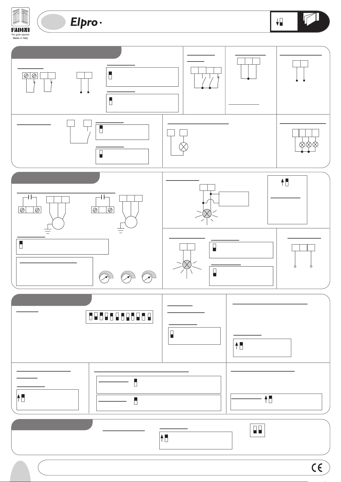
SLIDING GATES (DIP-SWITCH B No.1=ON)
X
®
LOW VOLTAGE ELECTRICAL CONNECTIONS
Photocells:
12 13
2
1
1st pair
Photocells
24V Output (500 mA)
(max. load:
2 pairs Photocells
1 radio Receiver)
Radio Contact:
- Open/Close (normal way)
- Travel is reversed by any
pulse
- Step by step
DIP-SWITCH A No.1
ON: 1st pair photocells stop gate while opening,
reverse it once obstacle is removed
OFF: photocells do not stop gate while opening,
1
reverse it on closing if obstructed
CONTACT
7
RADIO
DIP-SWITCH A No.2
DIP-SWITCH A No.5
3
COMMON
ELECTRIC POWER CONNECTIONS
Capacitor and 230V
single-phase motor:
Up to 0.5HP (0.36KW)
Capacitor C1
Motor M1
Connect to M1 or M2 both if two sliding
gate operators are required (if set to Sliding
Gate, motors start together)
17
16
18
COMMON
0.5 HP
M1
MOTOR
ON: No reversing on opening
OFF: Any pulse reverses gate
2
ON: Step by Step. Stop in between
OFF: Normal operating mode
5
Push Button Switch:
4
3
5
6
STOP
CLOSE
OPEN
BUTTON
PUSH
COMMON
Limit Switch:
8
9
10
OPEN
COMMON
LIMIT SWITCH
CLOSE
LIMIT SWITCH
PLEASE NOTE: If no
limit switches are
required, link out
terminals 8 and 10
with 9 or 3
24V 3W Gate Status Light:
3
: connect up to 0.5HP (0.36KW) motors to either terminal output,
ANT
T
IMPOR
connect up to 1.0HP (0.73KW) motors in parallel with with the following terminals:
terminal 16 with 19; terminal 17 with 20; terminal 18 with 21.
N.W: With 1.0HP motors, replace F1 and F2 fuses with 6.3A ones
Up to 1.0HP (0.72 KW) motor
17
16
18
COMMON
C1
Capacitor
Motor M1
M1
Light On = Open gate
11
Light Off = Closed gate
Light flashes fast= Closing gate
Light flashes normally= opening gate
Light flashes slowly= gate is stopped
INDICATOR
24V MAX 3W
19
20
21
1.0 HP
MOTOR
Pulin 3 buttons:
COMMON
Leds indicating
Open - Stop - Close pulses
MOTOR
RUN TIME
+
-
DWELL TIME
+
-
2627283
Flashing Lamp:
22
23
230V max 25W
DIP-SWITCH A No.4
ON: Pre-flashing
OFF: No pre-flashing
4
DIP-SWITCH A No.10
ON: Flashing lamp out of service during
Dwell Time, Automatic Mode
OFF: Flashing lamp in service during
10
Dwell Time, Automatic Mode
Power Supply:
24
NEUTRAL
POWER SUPPLY
230V
SINGLE-PHASE
FUNCTIONS OF DIP-SWITCH A
Dip-Switch A
1= ON. Photocells. Stop during Opening
ON. Radio. No reversing during Opening
2=
3= ON. Automatic Closing
4= ON. Pre-flashing. In service
5= ON. Radio. Step by step
6= ON. One gate opens for pedestrians
7= ON. Stroke Reversing Pulse. Opening
8= ON. No delay on Opening. Motors start together
nd
pair Photocells in service
9= ON. 2
10= ON. Flashing lamp out of service during Dwell
11= ON. Reversing to Close during Open and Dwell cycles after photocell obstruction
12= ON. Memory of the Times in Sevice
Safety Edge:
If the safety edge is activated during Open or
Close cycles, gate travel is shortly reversed;
this is controlled by Dip-Switch A No.8=ON
Reversing Operation Time can be increased
2
1
Safety Edge
Contact
123456789101112
DIP-SWITCH A No.8
ON: Increase Reversing Time
OFF: No time increase
8
DIP-SWITCH A No.9
ON: Reverse Gate Travel
OFF: No reversing
N.W: If no safety edge is fitted, no need to
9
link out the respective terminals
25
LIVE
±10% 50/60Hz
FUNCTIONS OF DIP-SWITCH B
Deadman Control:
DIP-SWITCH B No.2
ON: Hold-on-Switched control
OFF: Standard Operating Mode
2
Pedestrian Opening:
On selecting Sliding Gate Mode, the
Gate Delay Closing Trimmer is changed to control
Gate in fully closed position; an Open pulse opens the gate a span equals to
the time set by
DIP-SWITCH A No.6
Pedestrian Trimmer
ON: Pedestrian Service
OFF: Standard Operating Mode
6
Re-closing on passing by
the photocells:
DIP-SWITCH A No.11
Gate is reversed to close during Open and
ON:
Dwell cycles. Dip-Switch A No.11=ON
Closing is 3 seconds after the photocell
beam has been cleared
11
OFF:
Standard Operating Mode
Pedestrian mode
PEDESTRIAN
-
Automatic/
Semi-automatic
DIP-SWITCH A No.3
+
ON: Automatic closing
OFF: Closing by Pulse
3
1 2
Drwg. No.
4090
7
Page 4
1
ON
OFF
DIP-SWITCH B
®
GB
OIL-HYDRAULIC SWINGING GATE (DIP-SWITCH B No.1=OFF)
X
LOW VOLTAGE ELECTRICAL CONNECTIONS
Photocells:
1122
2nd pair
Photocells
1st pair
Photocells
Radio Contact:
- Open/Close (normal way)
- Travel is reversed by any
pulse
- Step by step
13
24V Output (500 mA)
(max. load:
2 pairs Photocells
1 radio Receiver)
3
COMMON
CONTACT
7
RADIO
DIP-SWITCH A No.1
1
DIP-SWITCH A No.9
9
DIP-SWITCH A No.2
ON: No reversing on opening
OFF: Any pulse reverses gate
2
DIP-SWITCH A No.5
ON: Step by Step. Stop in
OFF: Normal operating mode
5
ELECTRIC POWER CONNECTIONS
Capacitor and Single-phase Motor (230V):
161917
18
COMMON
Capacitor C1
Motor M1
DIP-SWITCH A No.8
ON: No delay during opening Motors start together
OFF: One gate is delayed by 2 seconds
8
M1
Delayed
on closing
WITH SINGLE SWINGING GATES:
1) Connect motor to M1 (terminals 16-17-18)
2) Set to No Delay during Opening
Dip-Switch A No.8=ON
3) Set Delay-on-Closing Trimmer to zero (lowest-)
by turning it anti-clockwise completely
Capacitor C2
Motor M2
MOTOR
RUN TIME
-
+
st
pair photocells stop gate while opening,
ON: 1
reverse it once obstacle is removed
nd
pair photocells do no stop gate while
OFF: 2
opening, reverse it on closing if obstructed
ON: 2nd pair photocells in service
nd
OFF: 2
pair photocells not required
(no need to link out terminals)
between
20
DWELL
TIME
M2
+
21
Delayed
on opening
DELAY ON
CLOSING
-
+
COMMON
-
Push Button
Switch:
3456
SWITCH
PUSH BUTTON
COMMON
OPEN
CLOSE
STOP
24V 3W Gate Status Light:
311
INDICATOR
24V MAX 3W
Light On = Open gate
Light Off = Closed gate
Light flashes fast= Closing gate
Light flashes normally= opening gate
Light flashes slowly= gate is stopped
Electric Latch:
22
23
Flashing Lamp:
22
23
230V max 25W
DIP-SWITCH A No.4
ON: Pre-flashing
OFF: No pre-flashing
4
DIP-SWITCH A No.10
ON: Flashing lamp out of service during
OFF: Flashing lamp in service during
10
Limit Switch:
10
89
CLOSE
PLEASE NOTE WELL: If no limit
switches are fitted, link out terminals
8 and 10 with common 9 or 3
Electric Latch
230 Vac
Flashing Lamp
230V max 25W
Dwell Time, Automatic Mode
Dwell Time, Automatic Mode
OPEN
COMMON
LIMIT SWITCH
LIMIT SWITCH
Gate electric lock:
14 15
Electric lock output
lock fitted to gate operated by
M1 motor (delayed on closing)
Pulin3 Button Switch
28
3
COMMON
Leds indicating
Open - Stop - Close pulses
ON
OFF
10
DIP-SWITCH A No.10
To be parallel connected
to the flashing lamp, to be
out of service during
Dwell Time, Automatic
mode: Dip-Switch A
No.10=ON
Power Supply:
24
NEUTRAL
POWER SUPPLY
230V ±10% 50/60Hz
SINGLE-PHASE
12V c.a.
max 15VA
26
27
25
LIVE
FUNCTIONS OF DIP-SWITCH A
Dip-Switch A
1= ON. Photocells. Stop during Opening
2=
ON. Radio. No reversing during Opening
3= ON. Automatic Closing
4= ON. Pre-flashing. In service
5= ON. Radio. Step by step
6= ON. One gate opens for pedestrians
7= ON. Stroke Reversing Pulse. Opening
8= ON. No delay on Opening. Motors start together
9= ON. 2nd pair Photocells in service
10= ON. Flashing lamp out of service during Dwell
11= ON. Reversing to Close during Open and Dwell cycles after photocell obstruction
12= ON. Memory of the Times in Service
Stroke Reversing Pulse
Opening:
DIP-SWITCH A No.7
ON: Stroke Reversing Pulse.
In service on Opening Gates in
closed position
OFF: Stroke Reversing Pulse out of
7
service
FUNCTIONS OF DIP-SWITCH B
8
Drwg. No.
123456789101112
Re-closing on passing by the photocells:
DIP-SWITCH A No.11
DIP-SWITCH A No.9
ON: Re-closing during Open and Dwell cycles.
11
OFF: Standard Operating Mode
ON: If a 2nd pair of photocells have been fitted
OFF: If only 1st pair photocells have been fitted
9
Deadman Control:
4090
Automatic/
Semi-automatic
DIP-SWITCH A No.3
ON: Automatic Closing
OFF: Closing by Pulse
3
Dip-Switch A No.11=ON Re-closing is after 3 seconds
after the photocell beam has been cleared
DIP-SWITCH B No.2
ON: Hold-on-Switched control
OFF: Standard Operating Mode
2
Pedestrian Opening (M1 Motor):
With gate in closed position, on pulsing Open one gate
leaf only is opened:
- The first Open pulse operates M1 Motor
- A second Open pulse operates the M2 motor
DIP-SWITCH A No.6
ON: 1 gate opens for pedestrian
OFF: Standard Operating Mode
6
For heavy duty applications
There can be cases where reversing operations are very
frequent (block of flats or factories). A function can be activated
in such cases, and the remaining motor run time is accounted
for when reversing or photocell crossing occur.
DIP-SWITCH A No.12
1 2
ON: Memory of the Times in service
OFF: Standard Operating Mode
12
Page 5

1
ON
OFF
DIP-SWITCH B
GB
GARAGE DOORS. 1 or 2 MOTORS (DIP-SWITCH B No.1=ON)
X
®
LOW VOLTAGE ELECTRICAL CONNECTIONS
Photocells:
12 13
2
1
1st pair
Photocells
24V Output (500 mA)
(max. load:
2 pairs Photocells
1 radio Receiver)
Radio Contact:
- Open/Close (normal way)
- Travel is reversed by any
pulse
- Step by step
DIP-SWITCH A No.1
ON: 1st pair photocells stop gate while opening,
reverse it once obstacle is removed
OFF: photocells do not stop gate while opening,
1
reverse it on closing if obstructed
CONTACT
RADIO
DIP-SWITCH A No.2
7
ON: No reversing on opening
OFF: Any pulse reverses gate
2
DIP-SWITCH A No.5
ON: Step by Step. Stop in between
OFF: Normal operating mode
5
3
COMMON
ELECTRIC POWER CONNECTIONS
Capacitor and single-phase electric motor (230V):
161917
Capacitor C1
Motor M1
COMMON
M1
MOTOR
RUN TIME
18
Capacitor
Motor M2
DWELL
TIME
COMMON
C2
20
M2
Push Button
Switch:
4
3
5
6
CLOSE
OPEN
PUSH BUTTON
COMMON
24V 3W Gate Status Light:
3
24V MAX 3W
Light On = Open gate
11
Light Off = Closed gate
Light flashes fast= Closing gate
Light flashes normally= opening gate
Light flashes slowly= gate is stopped
INDICATOR
Flashing Lamp:
21
22
23
230V max 25W
STOP
DIP-SWITCH A No.4
DIP-SWITCH A No.10
10
Limit Switch:
9
10
OPEN
COMMON
PLEASE NOTE: If no
limit switches are
required, link out
terminals 8 and 10
with 9 or 3
LIMIT SWITCH
8
CLOSE
LIMIT SWITCH
ON: Pre-flashing
OFF: No pre-flashing
4
ON: Flashing lamp out of service during
Dwell Time, Automatic Mode
OFF: Flashing lamp in service during
Dwell Time, Automatic Mode
Pulin 3 buttons:
28
26
27
3
COMMON
Leds indicating
Open - Stop - Close pulses
Gate electric lock:
15
14
12V c.a.
max 15VA
Electric lock output lock fitted to
gate operated by M1 motor
(delayed on closing)
Power Supply:
24
25
NEUTRAL
LIVE
POWER SUPPLY
±10% 50/60Hz
230V
SINGLE-PHASE
+
-
+
-
Electric Latch:
22
23
Electric Latch
230Vac
Flashing lamp
230V max 25W
DIP-SWITCH A No.10
To be parallel connected to the
ON
Flashing lamp, to be out of
service during Dwell Time,
OFF
Automatic mode: Dip-Switch A
10
No.10=ON
FUNCTIONS OF DIP-SWITCH A
Dip-Switch A
1= ON. Photocells. Stop during Opening
2=
ON. Radio. No reversing during Opening
3= ON. Automatic Closing
4= ON. Pre-flashing. In service
5= ON. Radio. Step by step
6= ON. No function
7= ON. No function
8= ON. No delay on Opening. Motors start together
nd
pair Photocells in service
9= ON. 2
10= ON. Flashing lamp out of service during Dwell
11= ON. Reversing to Close during Open and Dwell cycles after photocell obstruction
12= ON. Memory of the Times in Sevice
Safety Edge:
If the safety edge is activated during Open
or Close cycles, gate travel is shortly
reversed; this is controlled by Dip-Switch
A No.8=ON Reversing Operation Time can
be increased
2
1
Safety Edge
Contact
123456789101112
DIP-SWITCH A No.8
ON: Increase Reversing Time
OFF: No time increase
8
DIP-SWITCH A No.9
ON: Reverse Gate Travel
OFF: No reversing
N.W: If no safety edge is fitted, no need to
9
link out the respective terminals
FUNCTIONS OF DIP-SWITCH B
Deadman Control:
Automatic/
Semi-automatic
DIP-SWITCH A No.3
ON: Automatic Closing
OFF: Closing by Pulse
3
DIP-SWITCH B No.2
ON: Hold-on-Switched control
OFF: Standard Operating Mode
2
For heavy duty applications:
There can be cases where reversing operations are very frequent
(block of flats or factories). A function can be activated in such
cases, and the remaining motor run time is accounted for when
reversing or photocell crossing occur.
DIP-SWITCH A No.12
ON: Memory of the Times in service
OFF: Standard Operating Mode
12
Re-closing on passing by the photocells:
DIP-SWITCH A No.11
ON:
Gate is reversed to close during Open and Dwell cycles. Dip-Switch A
No.11=ON Closing is 3 seconds after the photocell beam has been
cleared
11
OFF: Standard Operating Mode
1 2
Drwg. No.
4090
9
Page 6
®
X
I
Ditta Costruttrice:
Via Mantova 177/A - 37053 Cerea (VR) Italy Tel. 0442 330422 - Fax 0442 331054
®
e-mail: info@fadini.net - www.fadini.net
s.n.c.
DICHIARAZIONE DI CONFORMITÀ
DICHIARA SOTTO LA PROPRIA RESPONSABILITÀ CHE:
Modello:
programmatore elettronico a microprocessore
X
È CONFORME ALLA DIRETTIVA MACCHINE .........98/37/CE
L'Elpro X viene commercializzato per essere installato come "impianto automatizzato", con accessori e componenti originali indicati dalla Ditta Costruttrice.
La ditta costruttrice non si assume responsabilità circa l'uso improprio del prodotto.
Il prodotto risulta conforme alle seguenti normative specifiche:
- Direttiva Bassa Tensione............................................................................2006/95 CE
- Direttiva Compatibilità Elettromagnetica....................................................2004/108/CEE e 92/31 CEE
Al fine di certificare il prodotto il Costruttore dichiara sotto la propria responsabilità il rispetto
della NORMATIVA DI PRODOTTO .........................EN 13241-1
Data:
GB
Manufacturer:
09-06-08
Il Responsabile
MANUFACTURER'S DECLARATION OF CONFORMITY
Via Mantova 177/A - 37053 Cerea (VR) Italy Tel. 0442 330422 - Fax 0442 331054
®
e-mail: info@fadini.net - www.fadini.net
s.n.c.
HEREBY DECLARES UNDER ITS OWN RESPONSIBILITY THAT:
Model:
X
electronic microprocessor programmer
L1 L2 L3 L4 L5 L6 L7 L8
L1 L2 L3 L4 L5 L6 L7 L8
L9
L9
1617181920212223123456789101112131415 24 25
1617181920212223123456789101112131415 24 25
COMPLIES WITH MACHINERY DIRECTIVE .........98/37/EC
Elpro X is sold for installation as an automated system, with original accessories and components indicated by the Manufacturer.
The Manufacturer declines all responsibility for improper use of the product.
The product is conforming to the following specific regulations:
- Low Voltage Directive ..............................................................................
2006/95 CE
- Electromagnetic Compatibility Directive ...................................................2004/108/CEE & 92/31 CEE
In order to certify the product, the Manufacturer declares under its own responsibility that it complies
with PRODUCT STANDARD .........................EN 13241-1
Date:
F
Constructeur:
09-06-08
Supervisor
DECLARATION DE CONFORMITE
Via Mantova 177/A - 37053 Cerea (VR) Italy Tel. 0442 330422 - Fax 0442 331054
®
e-mail: info@fadini.net - www.fadini.net
s.n.c.
DECLARE SOUS SA PROPRE RESPONSABILITE QUE :
Modèle
programmateur électronique à microprocesseur
X
EST CONFORME A LA DIRECTIVE MACHINES………98/37/CE
L’Elpro X est vendu pour être monté comme « installation automatisée », avec les accessoires et les composants originaux indiqués par le Constructeur.
Le fabricant décline toute responsabilité en cas d’usage impropre du produit.
Le produit est conforme aux normes suivantes:
- Directive Basse Tension ...........................................................................
- Directive Compatibilité Electromagnétique ...............................................2004/108/CEE et 92/31 CEE
2006/95 CE
L1 L2 L3 L4 L5 L6 L7 L8
L9
1617181920212223123456789101112131415 24 25
26
Date:
09-06-08
Dis. N.
Afin de certifier le produit, le Fabricant déclare sous sa propre responsabilité qu'il est conforme à
la NORME DE PRODUIT........................EN13241-1
Le Responsable
4090
Page 7

200
182
260 280
110
I -
Prima dell'installazione da parte di personale tecnico qualificato, si consiglia di prendere visione del
Libretto Normative di Sicurezza che la Meccanica Fadini mette a disposizione.
GB -
Please note that installation must be carried out by qualified technicians following Meccanica Fadini's
Safety Norms Manual.
F -
L'installation doit être effectuée par un technicien qualifié suivant le manuel des Normes de Sécurité
de Meccanica Fadini.
D -
Vor der Montage durch einen Fachmann, wird es empfohlen die Anleitung zur Sicherheitsnormen, die
Meccanica Fadini zur Verfügung stellt, nachzulesen.
E -
Antes de la instalación por el personal técnico calificado, se recomienda leer detenidamente el Folleto
de la Reglamentación de Seguridad que la empresa Meccanica Fadini pone a su disposición.
NL -
Voordat de installatie door gekwalificeerd technisch personeel wordt uitgevoerd, wordt geadviseerd
om het boekje met veiligheidsvoorschriften dat Meccanica Fadini ter beschikking stelt door te lezen.
Direttiva 2003/108/CE
Smaltimento dei materiali
I
elettrici ed elettronici
VIETATO GETTARE NEI RIFIUTI
MATERIALI NOCIVI PER L’AMBIENTE
2003/108/CE Directive
for waste electrical and
GB
electronic equipments
DISPOSE OF PROPERLY
ENVIRONMENT-NOXIOUS MATERIALS
®
s.n.c.
Via Mantova, 177/A - 37053 Cerea (Verona) Italy - Tel. +39 0442 330422 r.a. - Fax +39 0442 331054
e-mail: info@fadini.net - www.fadini.net
La ditta costruttrice si riserva di apportare modifiche al presente libretto senza preavviso
 Loading...