

Page 1

pag. 1,2,3,4
®
I
GB
F
D
LIBRETTO DI ISTRUZIONI
PLUS
9
PER CANCELLI A BATTENTE
INSTRUCTIONS
PLUS
9
FOR SWINGING GATES
NOTICES D’INSTRUCTION
PLUS
9
POUR PORTAILS A BATTANTS
ANLEITUNG
PLUS
9
FÜR DREHTORE
- MEMORIA DEI TEMPI DI LAVORO - FUNZIONE PASSO PASSO
- APERTURA PEDONALE - COLPO D’ARIETE
- SPIA DI SEGNALAZIONE DELLO STATO DELL’AUTOMAZIONE
- LUCE DI CORTESIA O ELETTROSERRATURA TEMPORIZZATA
- FUNZIONE OROLOGIO
- MEMORY OF WORKING TIMES - STEP BY STEP MODE
- PARTIAL PEDESTRIAN OPENING - STROKE REVERSING PULSE
- GATE STATUS INDICATION BY LEDs
- COURTESY LIGHT OR TIMED ELECTRIC LOCK
- TIME CLOCK MODE
- MEMOIRE DES TEMPS DE TRAVAIL - FONCTION PAS-PAS
- OUVERTURE PIETONS - COUP DE BELIER
- VOYANT DE DIAGNOSTIC DE L’ETAT DE L’AUTOMATISME
- LUMIERE DE COURTOISIE OU ELECTROSERRURE TEMPORISEE
- FONCTION HORLOGE
- EINSTELLZEITENSPEICHERUNG - IMPULSBETRIEB
- GEHTÜRFUNKTION
- RUCKARTIGE NACHZIEHBEWEGUNG ZUR ENTBLOCKUNG DES E-SCHLOSSES
- LED-FUNKTIONSKONTROLLE
- BELEUCHTUNG ODER E-SCHLOß MIT ZEITSCHALTER
- UHRFUNKTION
page 1,5,6,7
page 1,8,9,10
Seite 1,11,12,13
E
NL
Dis. N.
4192
FOLLETO DE INSTRUCCIONES
PLUS
9
PARA VERJAS DE BATIENTE
HANDLEIDING
PLUS
9
VOOR DRAAIHEKKEN
- MEMORIA DE LOS TIEMPOS DE TRABAJO - FUNCIÓN PASO-PASO
- ABERTURA PEATONAL - GOLPE DE ARIETE
- INDICADOR SEÑALIZACIÓN DEL ESTADO DE AUTOMACIÓN MANUAL DE INSTRUCCIONES
- LUZ INTERIOR O ELECTROCERRADURA TEMPORIZADA
- FUNCIÓN RELOJ
- GEHEUGEN VAN DE WERKTIJDEN - STAP-VOOR-STAP FUNCTIE
- VOETGANGERSDOORGANG - EINDSTOOT
- SIGNALERINGSLAMP AUTOMATISERINGSSTATUS
- SIGNALERINGSLAMP OF GETIMED ELEKTROSLOT
- KLOKFUNCTIE
Via Mantova, 177/A - C.P. 126 - 37053 Cerea (Verona) Italy - Tel. +39 0442 330422 r.a.
®
Fax +39 0442 331054 - e-mail: info@fadini.net - www.fadini.net
s.n.c.
pág. 1,14,15,16
pag. 1,17,18,19
1
Page 2
GB
-
+
T1
MOTOR RUN TIME
max 64s
L2
L8
PAIR No.2
PHOTOCELLS.
9
-
DWELL TIME
max 128s
L3
L4
1
2
3
COMMON
SAFETY EDGES
PHOTOCELLS. PAIR No.1 AND
PLUS
+
DIP-SWI TCH
2
1
3
L5
L6
CLOSE
OPEN
-
+
T3T2
GATE DELAY TIME
max 12s
PLUG-IN
RADIO PCB
CONNECTOR
6
4
7
5
74
85
COMMON
RADIO
STOP
FOR SWINGING GATES
-
+
T4
- STROKE REVERSING PULSE + ELEC. LOCK= 0
- ELECTRIC LOCK = from above minimum to centre
straight position to get 4s excitation time
- COURTESY LIGHT = 3 up to 128s by setting T4
Trimmer in any required position from centre setting
to maximum position
ON
OFF
8
96
LIGHT
RELAY TO OPERATE A COURTESY
L7
L9
13
11
10
12
24V max 3W
INDICATION LIGHT
12V AC OUTPUT FOR ELEC.LOCK OR
n°1 Radio Receiver
n°2 Pairs Photocells
24V OUTPUT
. Max. load:
3
26
2728
PULIN 3
COMMON
SINGLE-PHASE
MOTOR M1 (an
elec. lock may be
fitted to the gate)
24 V Protection
19
181617
COMMON
M1 M2
SINGLE-PHASE
MOTOR M2
F4=1,6A
20
21
L1
2322
230V 25W max
FLASHING LAMP
TRANSFORMER
F1=5A Mains
24 25
NEUTRAL
LIVE
230V ±10% 50Hz
SINGLE-PHASE
VOL
T
AGE SUPPL
Y
F3=630mA
Transformer
Protection
F2=5A Mains
®
GB
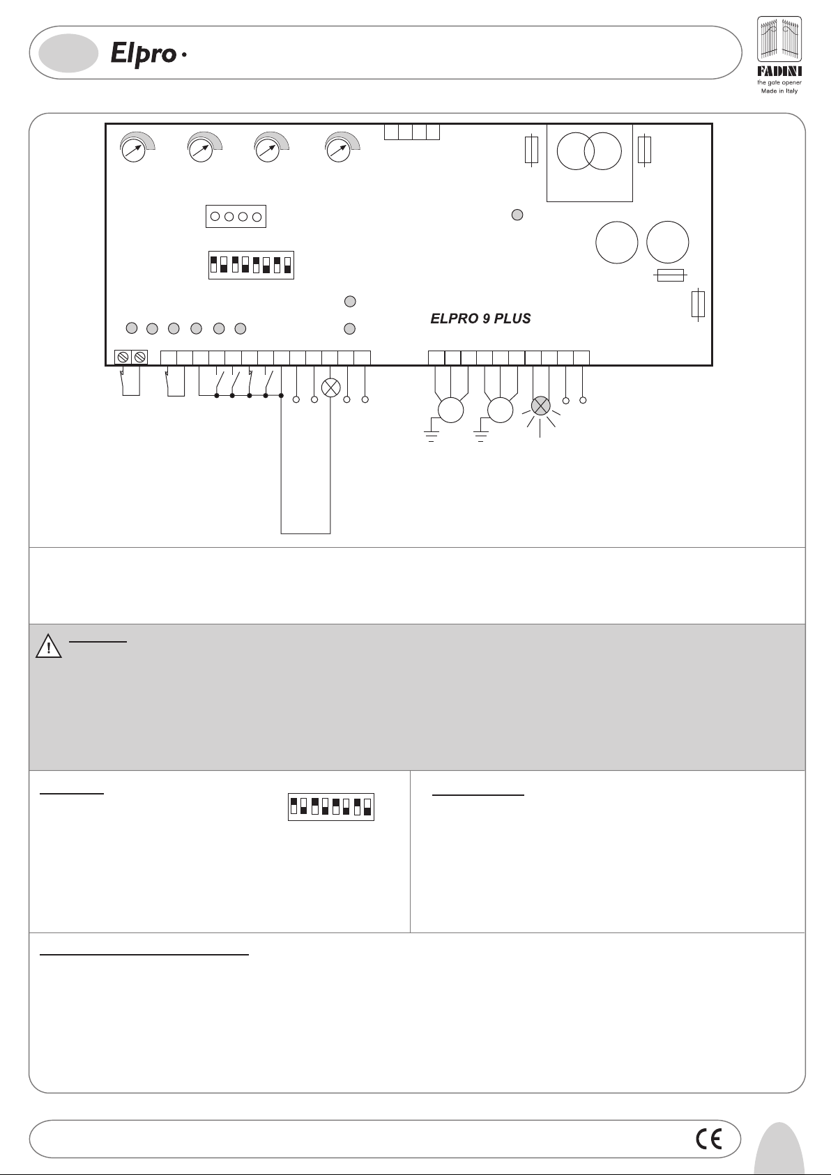
General description: the electronic control panel Elpro 9 Plus, new generation, is designed to operate swinging gates. Power supply is 230V single-phase. It is built in
full compliance with the Low Voltage 2006/95 CE and Electro-Magnetic Compatibility 2004/108/CE & 92/31 CEE Regulations. Fitting operations are recommended to be
carried out by a qualified technician in conformity to the existing safety standards. The manufacturing company declines any responsability for incorrect handling and
applications and reserves the right to change or update these instructions any time without previous notice. Failure to follow installation regalations may result in
serious damage to property and persons.
IMPORTANT:
- The control panel is to be installed in a dry sheltered place inside its protection box
- Make sure that the power supply to the electronic programmer is 230V ±10%
- Make sure that the power supply to the Electric Motor is 230V ±10%
- For distances of over 50 metres we recommend using electric cables with bigger sections.
- Fit the mains to the control panel with a 0.03A high performance magnetic-thermal circuit breaker
- Use 1.5 mm2 section wires for voltage supply, electric motor and flashing lamp for a max. distance of 50 m, and 1mm
section wires for the limit switches and the accessories
- Bridge terminals 1 and 2 if no photocells are required
- Bridge terminals 3 and 6 if no key- or push-button switches are required
N.W.: For applications such as light switching, CCTV etc. use solid state relays to prevent interference with the microprocessor
1
DIP-SWI TCH
2
3
ON
OFF
6
8
4
7
5
Trouble-shooting
- Make sure that the power supply to the electronic programmer
is 230V ±10%
- Make sure that the power supply to the Electric Motor is
230V ±10%
- Check fuses
- Check photocells. Contact normally closed
- Check all contacts. They must be N.C.
- Check that no voltage drop occurs between
Dip-Switch:
1= ON Photocells. Stop on opening
2= ON Radio. No reversing on opening
3= ON Automatic closing
4= ON Preflashing activated
5= ON Radio. Step by step. Stop in between
6= ON No lamp flashing on Dwell time, automatic mode
7= ON Memory of times in service
8= ON, 2 hour pulsing on gate in closed position
the control panel and the electric motor
2
Equipment Status Indication by LEDs:
L1= 230V mains supply is OK and F1,F2,F3,F4 fuses OK
L2= Photocells No.1 or Safety Edge normally illuminated
L3= Open. It illuminates whenever an Open pulse is given
L4= Close. It illuminates whenever a Close pulse is given
L5= Stop. It goes off whenever a Stop pulse is given
L6= Radio, It illuminates whenever a transmitter button is pressed
L7= 24V Gate Status Indicator. It flashes to indicate gate status
L8= Photocells No. 2. Normally illuminated
L9= Illuminated as long as the time set on T4 (Courtesy light)
Drwg. No.
4192
5
Page 3

GB
®
9
LOW VOLTAGE ELECTRICAL CONNECTIONS
PLUS
FOR SWINGING GATES
Photocells and Safety Edge:
2
1
PHOTOCELLS 2
CONTACT FOR PHOTOCELLS
AND SAFETY EDGE
Keyswitch:
Radio Contact:
- Open/Close (Standard)
- Any new pulse reverses gate travel
- Step by Step
Electric lock:
910
12VAC OUTPUT TO POWER
AN ELECTRIC LOCK
12 13
24V OUTPUT (500mm) ( MAX LOAD:
2 PAIRS PHOTOCELLS and
1 RADIO RECEIVER)
4
3
5
6
COMMON
RADIO CONTACT
STOP
OPEN
CLOSE
8
7
COMMON
By setting T4 Trimmer (Ext.Trimmer) from
above minimum position to straight
centre position, the electric lock is
excited for 4 seconds.
M1 motor is abled to take an electric
lock.
DIP-SWITCH 1:
ON: Photocells stop gates on Opening and reverse gate
travel on Closing once obstacle has been removed
OFF: Photocells do not stop gates on Opening, reverse
1
gate travel on Closing in case of an obstacle
DIP-SWITCH 2 and 5 (NEVER set both of them to ON at the same time):
ON: No gate travel reversing
on Opening
OFF:Any new pulse reverses gate travel
2
-
+
ON: Step by Step. Stop in between by
remote control
OFF: Standard Operating Mode as pre-set
5
T4 ABOVE MINIMUM TO
STRAIGHT CENTRE POSITION.
THE ELECTRIC LOCK IS
EXCITED FOR 4 SECONDS
24V 3W Light for Gate Status Indication:
Push Button Switch Pulin3:
8
27
28
Light On = Gate Open
11
Light Off = Gate Closed
Flashing 0,5s (fast)= Gate Closing
Flashing 1s (standard)= Gate opening
Flashing 2s (slow)= Gate Stopped
26
3
These LEDs indicate when
COMMON
Open - stop - Close
commands are given
6
Drwg. No.
4192
Page 4

GB
FUNCTIONS
ELECTRIC POWER CONNECTIONS
9
PLUS
FOR SWINGING GATES
®
Single-phase Motors (230V):
16 17
Flashing Lamp:
22
23
230V MAX 25W
COMMON
M1
Gate Delay
Close
DIP-SWITCH 4:
ON: Pre-flashing
OFF: No pre-flashing
4
18
19 20
COMMON
M2
Gate Delay
Open
DIP-SWITCH 6:
ON: Lamp is Out of Service on Dwell
Time on Automatic Mode
OFF: Lamp flashes on Dwell
6
Time on Automatic Mode
Automatic/ Semi-automatic:
Automatic Mode: On pulsing to Open, the gate starts opening, stops to dwell as pre-set on T2 trimmer,
on expiring of the pre-set time it starts closing automatically
Semi-automatic Mode: On pulsing to Open, the gate starts opening and stays open. A pulse to Close is
needed to close the gate
MOTOR RUN TIME
T1
-
max 64s
+
21
DWELL TIME
T2
-
-
max 128s
+
T3 GATE DELAY TIME:
0-3s= same Delay Time on Opening and Closing
+
longer than 3s= Delay Time is fixed 3 s on Opening
it varies from 3 to 12 s on Closing
DIP-SWITCH N°8
With gate in closed position,it
is possible to pulse gate to
close every two hours
ON: A pulse is given
every two hours
OFF: Two hours Pulsing
8
Out of Service
Voltage Supply:
24
25
NEUTRAL
LIVE
FADINI
T2
l'apricancello
-
Dwell Time
from 5 to 128s
SINGLE-PHASE VOLTAGE SUPPLY
DIP-SWITCH 3
+
ON= Automatic Closing
OFF= No Automatic Closing
3
±10% 50Hz
230V
Semi-automatic Mode
Pedestrian Partial Opening:
With the gate in closed position, it is possible to open the gate partially
by giving a pulse to terminals 3 and 4 for 2 to 6 seconds max:
- a first pulse to Open operates M1 motor to open
- a second pulse to Open operates the other gate (M2 motor)
Courtesy Light:
Connect a 24VAC Modular Relay to operate a Courtesy Light
Trimmer T4 from straight centre position to max. setting
position: time can be adjusted from 128s to 3s
Stroke Reversing Pulse on Opening:
Before the gate starts opening, it is first pushed to Close
direction for 3 seconds,a fixed time, to help the electric
lock to disengage.T4 trimmer to the lowest
Time Clock
Installation :
How it works: Set the clock to the required Open time. On the pre-set time the gate is automatically operated to open
and stays open. No other commands are accepted (not even by remote control) until the time pre-set on the clock is
expired. On expiring of the pre-set time, after the Dwell Time, the gate is automatically operated to close
Dip-Switch N°3=ON.
It is operated by giving an Open command superior to 6 seconds to terminals 3 and 4.
DIP-SWITCH N°3=ON Automatic Closing
ON= Automatic Closing
OFF= No Automatic Closing
3
Semi-automatic Mode
9
10
-
+
WITH T4 TO THE LOWEST THE TIME OF THE STROKE
-
REVERSING PULSE IS 3s AND THAT OF THE
+
ELECTRIC LOCK IS 4s
External Time Clock
43
COMMON
OPEN
N.O.
COMMON
Drwg. No.
4192
7
Page 5

200
182
03-2011
260 280
110
I-
Prima dell’installazione da parte di personale tecnico qualificato, si consiglia di prendere visione del
Libretto Normative di Sicurezza che la Meccanica Fadini mette a disposizione.
GB-
Please note that installation must be carried out by qualified technicians following Meccanica Fadini’s
Safety Norms Manual.
F-
L’installation doit être effectuée par un technicien qualifié suivant le manuel des Normes de Sécurité
de Meccanica Fadini.
D-
Vor der Montage von einem Fachmann, wird es empfohlen die Anleitung zur Sicherheitsnormen, die
Meccanica Fadini zur Verfügung stellt, nachzulesen.
E-
Antes de la instalación por el personal técnico calificado, se recomienda leer detenidamente el Folleto
de la Reglamentación de Seguridad que la empresa Meccanica Fadini pone a su disposición.
NL -
Vòòr installatie, dat door bevoegd technisch personeel moet worden uitgevoerd, wordt het aangeraden
de Handleiding met de Veiligheidsnormen door te lezen die Meccanica Fadini tot beschikking stelt.
®
s.n.c.
Via Mantova, 177/A - C.P. 126 - 37053 Cerea (Verona) Italy - Tel. +39 0442 330422 r.a. - Fax +39 0442 331054
e-mail: info@fadini.net - www.fadini.net
La ditta costruttrice si riserva di apportare modifiche al presente libretto senza preavviso
 Loading...