

Page 1
pag. 1,2,3
®
I
GB
F
D
LIBRETTO DI ISTRUZIONI
RP
7
PROGRAMMATORE ELETTRONICO PER NUPI 66
CON TECNOLOGIA RADIO PROGRAMMABILE
INSTRUCTIONS
RP
7
ELECTRONIC CONTROL PANEL FOR NUPI 66
WITH PROGRAMMABLE RADIO TECHNOLOGY
NOTICES D'INSTRUCTION
RP
7
PROGRAMMATEUR ELECTRONIQUE POUR NUPI 66
AVEC TECNOLOGIE RADIO PROGRAMMABLE
ANLEITUNG
RP
7
ELEKTRONISCHE STEUERUNG FÜR NUPI 66
MIT PROGRAMMIERBARER TECHNOLOGIE
- APPRENDIMENTO DEI TEMPI CON RADIO-TRASMETTITORE
- FUNZIONE AUTOMATICO-SEMIAUTOMATICO
- FUNZIONE PASSO-PASSO CON BLOCCO INTERMEDIO
- FUNZIONE AD ANTA PEDONALE
- DIP-SWITCH DI PROGRAMMAZIONE
- LEARNING TIMES BY REMOTE CONTROL
- AUTOMATIC/SEMI-AUTOMATIC OPERATING MODES
- STEP BY STEP MODE INTERMIDIATE STOP
- PARTIAL PEDESTRIAN OPENING
- DIP-SWITCH SETTING
page 1,4,5
- AUTOAPPRENTISSANT DES TEMPS PAR TELECOMMANDE
- FONCTION AUTOMATIQUE-SEMIAUTOMATIQUE
- FONCTION PAS-PAS AVEC ARRET INTERMEDIAIRE
- FONCTION VANTAIL PIETONS
- DIP-SWITCH DE PROGRAMMATION
page 1,6,7
- ERLERNUNG DER ZEITEN DURCH FUNKSENDER
- AUTOMATISCHE/HALBAUTOMATISCHE FUNKTION
- SCHRITT-IMPULS-FUNKTION MIT MITTELSTOPP
- GEHTÜRFUNKTION
- DIP-SCHALTER ZUR PROGRAMMIERUNG
Seite 1,8,9
E
NL
Dis. N.
FOLLETO DE INSTRUCCIONES
7
PROGRAMADOR ELECTRONICO PARA NUPI 66
CON TECNOLOGIA DE RADIO PROGRAMABLE
HANDLEIDING
7
RADIOPROGRAMMEERBARE ELEKTRONISCHE
PROGRAMMEEREENHEID VOOR NUPI 66
4153
RP
RP
- APRENDIZAJE DE LOS TIEMPOS POR MEDIO DE RADIOTRANSMISOR
- FUNCION AUTOMATICO-SEMIAUTOMATICO
- FUNCION PASO A PASO CON BLOQUEO INTERMEDIO
- FUNCION DE HOJA PARA PASO DE PEATONES
- “DIP-SWITCH” DE PROGRAMACION
pág. 1,10,11
- TIJDSLERING MET RADIOZENDER
- AUTOMATISCHE-HALFAUTOMATISCHE FUNCTIE
- STAP-VOOR-STAP FUNCTIE MET TUSSENTIJDSE BLOKKERING
- FUNCTIE MET VOETGANGERSPOORT
- PROGRAMMERINGSDIP-SWITCH
pag. 1,12,13
Via Mantova, 177/A - C.P. 126 - 37053 Cerea (Verona) Italy - Tel. +39 0442 330422 r.a.
®
Fax +39 0442 331054 - e-mail: info@fadini.net - www.fadini.net
s.n.c.
1
Page 2
®
GB
7
RP
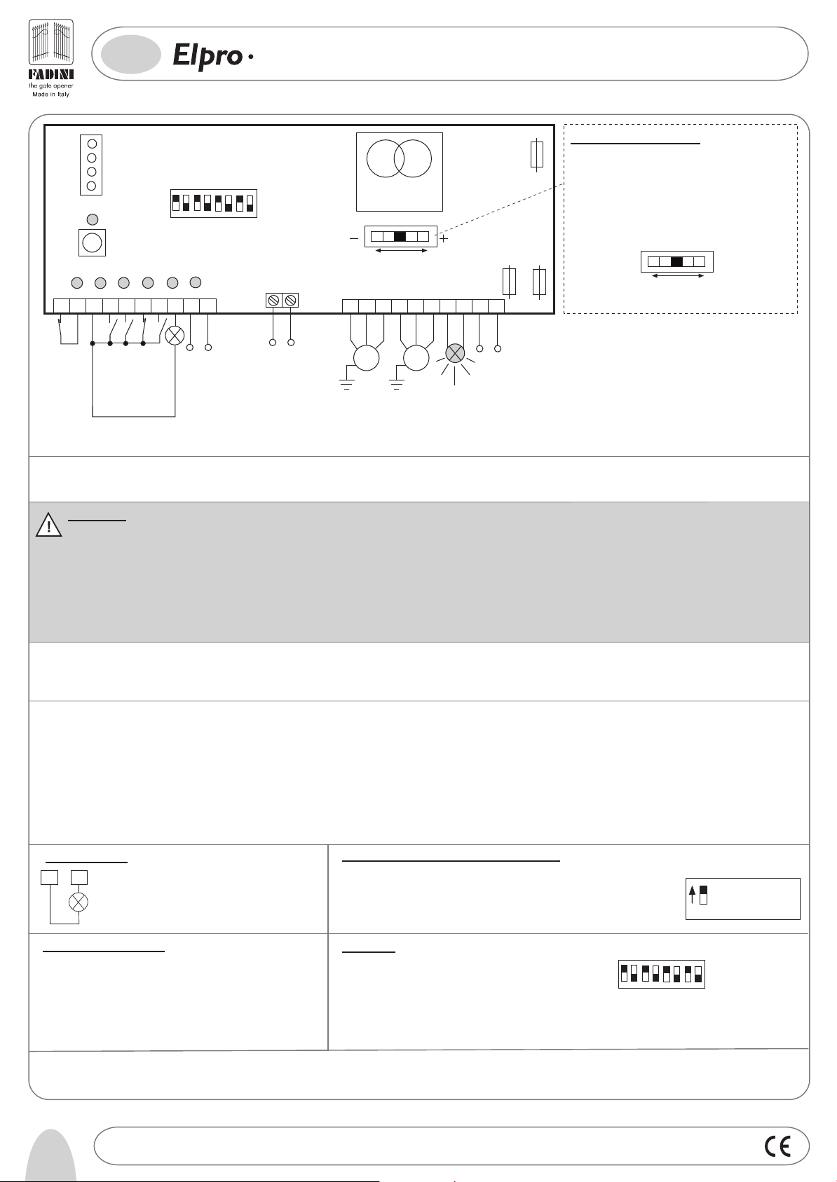
ELECTRONIC CONTROL PANEL FOR NUPI 66
WITH PROGRAMMABLE RADIO TECHNOLOGY
2A 24V low
voltage fuse
19
181617
N
E
U
TR
AL
PHASE POWER SUPPL
230V 25W max
FLASHING LAMP
Y
5 A line
fuse
20
LIVE
230V
±10% 50Hz SINGLE-
L7
Elpro 7 RP
L1
L2
1
2
3
COMMON
PHOTOCELLS NC
PLUG-IN RADIO
CARD SUPPORT
PROGRAMMING "P"
BUTTON
L3
L4
74
RADIO
CLOSE
STOP NC
OPEN
DIP-SWITCH
2
1
3
L5
L6
85
96
10
24V max 3W
INDICATOR
1 No. Radio receiver
2 Nos. photocells
ON
OFF
6
8
4
7
5
24 V OUTPUT max load:
COURTESY LIGHT
OR 12V AC RELAY FOR
ELECTRIC LOCK
ELECTRONIC TORQUE
11
12
C
O
M
M
O
N
M1
SINGLE-PHASE
MOTOR M1
(actuator and
electric lock if
required)
TRANSFORMER
12 453
CONTROL
13
1514
C
O
M
M
O
N
M2
SINGLE-
PHASE
MOTOR M2
General description: Elpro 7 RP is an electronic control panel developed for Nupi 66. The main feature of this unit is the capability to learn the required working times
during operation (gate delay in open and close cycles, dwell time). It is recommended to carry out the installation in strict compliance with the rules of good technique and
fit the system with ground stops in the Open and Closed positions.
IMPORTANT:
- The control panel must be installed in a sheltered, dry place, inside the box provided with it.
- Make sure that the power supply to the electronic programmer is 230V ±10%
- Make sure that the power supply to the Electric Motor is 230V ±10%
- For distances of over 50 metres we recommend using electric cables with bigger sections
- Fit the mains to the control panel with a 0.03A high performance circuit breaker.
- Use 1.5mm2 section wires for voltage supply, electric motor and flashing lamp. Maximum recommended distance 50m.
- Use 1mm
2
section wires for limit switches, photocells, push-buttons/key-switch and accessories.
- Bridge terminals 1 and 2 if no photocells are required.
- Bridge terminals 3 and 6 if no key- or push-button switches are required.
N.W.: To fit extra accessories such as lights, CCTV etc. use only solid state relays to prevent damages to the microprocessor
WORKING LOGIC: Elpro 7 RP is supplied with pre-set working times so that to allow the first installation: Working time is about 20 s
Gate Delay Times: - Opening=2 s - Closing=6 s - Dwell on automatic Mode=15 s
Once satisfied that the system is working all right, new working times can be programmed to meet the user's needs or the installation requirements.
Elpro 7RP functions can be set by Dip-switches, both before and after the times have been stored by the unit.
Adjust torque from lower level (step 1) up to the
required amount of power step by step to achieve
a correct performance of the system so that the
gates are operated as required and any injuring
hazard is prevented.
Please note, torque is to be adjusted by a technician.
5 A line
fuse
LESS POWER
12 453
ELECTRONIC
TORQUE CONTROL
MORE POWER
Torque control setting:
LEARNING THE TIMES: ELPRO 7 RP learning operation is quite easy and can be achieved either by the P button on the PBC or by the remote control after entering setting
mode, see point 1).
Starting the unit to learn the required times: with the gate in closed position pulse the equipment to one complete cycle, ie. open-stop/dwell-close
Important:
1) In order to avoid setting times which are not suitable with the correct gate functioning, some time limits were pre-set. Beyond these values the automation will start
with the maximum pre-set time:
M1 and M2 Motor Run time: max.55s Dwell time on Automatic Mode: maximum 90s
2) During the learning operation, no other functions can be activated, the Photocells and the Stop button are out of service
3) If the new setting operation is interrupted (for example: mains cut off), the times in the previous setting are memorized.
4) Normally, not on programming mode, the P button has the same function as a remote control button and it is possible to test the system by pulsing it;
the Led 7 becomes a simple indicator, the same as the indicator to terminal 8.
24V 3W Indicator:
3
8
COMMON
Led On = the Gate is Open
Led Off = the Gate is Closed
Fast Flash = closing movement
Slow Flash = opening movement
Led Status Indication:
L1=230V 50Hz power supply. Alight
L2=Photocells, if obstructed light goes off
L3=Open. Alight whenever an Open pulse is given
L4=Close. Alight whenever a Close pulse is given
L5=Stop. It goes off on pulsing Stop
L6=Radio. It goes on by pressing a transmitter button
L7=Gate Status; and programming led
Pedestrian Opening ( M1 Motor by Open pulse):
Partial opening for pedestrians is only allowed in closed gate position by
pulsing to Open (the gate closes after the dwell time if set to Automatic
Dip-Switch 3=ON)
-the first pulse operates 1 gate leaf (M1)
-the second pulse operates the second gate leaf
Dip-Switch:
1= ON Photocells, Stop during opening
DIP-SWITCH
2= ON Radio no reversing during Opening
3= ON Automatic Closing
4= ON Pre-flashing in service
5= ON Radio step by step
4
2
1
3
6= ON No delay on opening
7= ON No Additional pushing on the gate leaf after closing
8= ON Pedestrian opening by Open button
ON: 1 gate leaf for
pedestrian opening
OFF: Standard
operation
8
ON
OFF
6
8
7
5
Elpro 7 RP is to be powered with 230 V single-phase voltage. It is manufactured in conformity to 2006/95 CE Low Voltage Safety Norms and 2004/108/CE & 92/31 CEE Norms for the
Electro Magnetic Compatibility. Installation is to be carried out by qualified technicians in compliance with the existing safety regulations. The manufacturer is not liable for incorrect use
of the equipment and reserves the right to do changes to the unit and this manual any time.
Failure to follow installation regalations may result in serious damage to property and persons.
4
Drwg. No.
4153
Page 3

GB
7
RP
ELECTRONIC CONTROL PANEL FOR NUPI 66
WITH PROGRAMMABLE RADIO TECHNOLOGY
®
Preliminary notes to Learning Mode:
- Make sure that the gate is closed
- Make sure that the gate stops in the respective open and closed gate positions
are firmly fixed to the ground
1°
1°
st
1
Operation:
Cut off power supply to Elpro 7 RP by removing the 2A 24V Low
Voltage white Fuse, which is on the right upper side of the PCB
2°
2°
2nd
Operation:
Hold the button "P" pressed and re-power the PCB by inserting
the 24V Low Voltage Fuse back into its holder.
3°
3rd
Operation:
When the Led L7 illuminates, release button "P": Led L7 will flash
5 times and the flashing lamp will illuminate: the program "learning
working times" has been entered.
IMPORTANT: at this stage two options are allowed to go on with setting
ie. learning the required operating times: by the "P" button or by remote
!
control. The last option allows the installation agent to have direct visual
control of the operation being performed
by the gates.
L7
L7
L7
L7
7°
Birio
7th
Operation:
A pulse stops M2 motor
(second gate wide open on open gate stop)
The time passing from 7th to 8th operation is stored by the system as
"Dwell Time", in service on AUTOMATIC MODE (Dip No.3=ON) or out of service
!
(Dip No.3=OFF, dwell time still in the system memory but not applicable ).
M2
8°
Birio
th
Operation:
8
A Pulse to close starts M2 motor
(M2 gate starts closing)
The time between the 8th and 9th operations is stored by the system
!
as "Gate Delay Time on Closing Cycle"
M2
9°
M2
9th
Operation:
A pulse to close starts M1 motor
(M1 gate starts closing)
Birio
M1
M1
M1
Birio
4°
Birio
4th
Operation:
A pulse to open starts M1 motor
(the first gate starts opening)
The time passing from 4th to 5th operations is stored by the system as the
Gate Delay Time in Open Cycle, with the options in service (Dip No.6 =ON)
!
or out of service (Dip No. 6=OFF, the time is stored but no delay will occur).
M2
5°
M2
Birio
5th
Operation:
A pulse to open starts M2 motor
(second gate starts opening)
6°
6th
Operation:
A pulse stops M1 motor
(first gate wide open on open gate stop)
Birio
M2
M1
M1
M1
10°
M1
M2
Birio
10th
Operation:
A pulse stops M2 motor (M2 gate on closed gate position)
In order to ensure that the gate is securely held in stop position, it is advised to
pulse the actuator ie. gate to stop approx. 3-4 seconds after the gate has reached
the end of the permitted stroke on the closed gate stop position.
11°
M1
M2
Birio
11th
Operation:
A pulse stops M1 motor (M1 gate on closed gate position)
In order to ensure that the gate is securely held in stop position, it is advised to
pulse the actuator ie. gate to stop approx. 3-4 seconds after the gate has reached
the end of the permitted stroke on the closed gate stop position.
The 11th operation concludes the procedure for the control panel to learn the
required working times.
After the learning procedure it is possible to set the operating modes either ON/OFF
as required by means the Dip-switches on the PCB
Drwg. No.
4153
5
Page 4

200
182
06-2010
260 280
110
I -
Prima dell'installazione da parte di personale tecnico qualificato, si consiglia di prendere visione del
Libretto Normative di Sicurezza che la Meccanica Fadini mette a disposizione.
GB -
Please note that installation must be carried out by qualified technicians following Meccanica Fadini's
Safety Norms Manual.
F -
L'installation doit être effectuée par un technicien qualifié suivant le manuel des Normes de Sécurité
de Meccanica Fadini.
D -
Vor der Montage durch einen Fachmann, wird es empfohlen die Anleitung zur Sicherheitsnormen, die
Meccanica Fadini zur Verfügung stellt, nachzulesen.
E -
Antes de la instalación por el personal técnico calificado, se recomienda leer detenidamente el Folleto
de la Reglamentación de Seguridad que la empresa Meccanica Fadini pone a su disposición.
NL -
Voordat de installatie door gekwalificeerd technisch personeel wordt uitgevoerd, wordt geadviseerd
om het boekje met veiligheidsvoorschriften dat Meccanica Fadini ter beschikking stelt door te lezen.
Direttiva 2003/108/CE
Smaltimento dei materiali
I
elettrici ed elettronici
VIETATO GETTARE NEI RIFIUTI
MATERIALI NOCIVI PER L’AMBIENTE
2003/108/CE Directive
for waste electrical and
GB
electronic equipments
DISPOSE OF PROPERLY
ENVIRONMENT-NOXIOUS MATERIALS
®
s.n.c.
Via Mantova, 177/A - C.P. 126 - 37053 Cerea (Verona) Italy - Tel. +39 0442 330422 r.a. - Fax +39 0442 331054
e-mail: info@fadini.net - www.fadini.net
La ditta costruttrice si riserva di apportare modifiche al presente libretto senza preavviso
 Loading...