

Page 1
pag. 2,3,4
®
I
GB
F
D
LIBRETTO DI ISTRUZIONI
70/3
PER SCORREVOLE MEC 200
70/3
SINGLE-/THREE-PHASE
FOR SLIDING GATE OPERATORS MEC 200
NOTICES D'INSTRUCTION
70/3
MONOPHASE - TRIPHASE
POUR PORTAILS COULISSANTS MEC 200
70/3
EINPHASIG - DREIPHASIG
FÜR SCHIEBETORANTRIEB MEC 200
PLUS
MONOFASE - TRIFASE
INSTRUCTIONS
PLUS
PLUS
ANLEITUNG
PLUS
- FUNZIONE PASSO PASSO
- APERTURA PEDONALE
- UOMO PRESENTE
- SPIA DI SEGNALAZIONE DELLO STATO DELL’AUTOMAZIONE
- LUCE DI CORTESIA TEMPORIZZATA
- STEP BY STEP
- PEDESTRIAN OPENING
- HOLD-ON SWITCHED (DEADMAN) CONTROL
- GATE STATUS INDICATION
- ADJUSTABLE COURTESY LIGHT TIME
page 5,6,7
- FONCTION PAS PAS
- OUVERTURE PIETONS
- FONCTION HOMME MORT
- SIGNALISATION DE L'ETAT DE L'AUTOMATISME PAR VOYANT
- LAMPE TEMOIN TEMPORISEE
page 8,9,10
- SCHRITT-IMPULS-FUNKTION
- TOTMANN-BEDIENUNG
- GEHTÜRFUNKTION
- AUTOMATION-ZUSTAND ANZEIGELAMPE
- EINSTELLBARE DECKENLEUCHTEZEIT
Seite 11,12,13
E
NL
Dis. N.
4138
FOLLETO DE INSTRUCCIONES
70/3
MONOFASICO - TRIFASICO
PARA VERJAS DESLIZANTES MEC 200
70/3
VOOR SCHUIFHEKOPENER MEC 200
PLUS
HANDLEIDING
PLUS
EENFASE-DRIEFASE
- FUNCIONAMIENTO PASO A PASO
- ABERTURA PARA PASO DE PEATONES
- HOMBRE PRESENTE
- LÁMPARA TESTIGO QUE SEÑALA EL ESTADO DEL AUTOMATISMO
- LUZ AUXILIAR TEMPORIZADA
pág. 14,15,16
- STAP-VOOR-STAP FUNCTIE
- VOETGANGERSDOORGANG
- DODEMANSFUNCTIE
- SIGNALERINGSLAMP AUTOMATISERINGSSTATUS
- INSTELBARE INDICATIELAMP
pag. 17,18,19
Via Mantova, 177/A - 37053 Cerea (Verona) Italy - Tel. +39 0442 330422 r.a.
®
Fax +39 0442 331054 - e-mail: info@fadini.net - www.fadini.net
s.n.c.
1
Page 2
GB
70/3
PLUS
SINGLE-/THREE-PHASE FOR SLIDING GATE OPERATORS MEC 200
®
L1
L10
L8
L7
L9
1514
COMMON
COURTESY LIGHT
LIMIT SWITCH OPEN
TRANSFORMER
F6=630mA for 24V
protection
191816 17
20 21
OR 12V AC RELAY FOR 230V
ELECTRIC LOCK
SUPPLY
24V PHOTOCELL
SAFETY SWITCH
230V 25W max
400V
230V
2322
FLASHING LAMP
W
16µF CAPACITOR for
single-phase application
F4=630mA
Transformer
Protection
F5=1A Flashing
Lamp Protection
25 2624 292827
COM.
U
V
M
MOTOR
F3=8A Mains
LIVE
S
R
230V
SINGLE-PHASE
POWER SUPPLY
230/400V
THREE-PHASE
POWER SUPPLY
F1=8A Mains
F2=8A Mains
LIVE
T
50Hz
±10%
50Hz
±10%
NEUTRAL
DIP-SWITCH
4
2
1
3
1
2
3
POWER SUPPLY
24V RADIO
INDICATION LAMP CLOSE
+24 SPIA
ON
OFF
6
8
7
5
5
6
STOP
COMMON
7
CLOSE
4
INDICATION LAMP OPEN
8
OPEN
9
INDICATION
LIGHT
24V max 3W
DWELL TIME
T2
from 5 to 150s
-
10
RADIO CONTACT
RADIO
PLUG-IN
CARD CONNECTOR
L3
L5
PEDESTRIAN TIME
T3
from 3 to 30s
+
-
-
-
+
T1
MOTOR RUN TIME
from 5 to 150s
+
L2
L4
L6
T4
EXT TIME (Electric lock &
Courtesy Light) from 2 to 255s
+
11 12
13
PHOTOCELL CONTACT
LIMIT SWITCH CLOSE
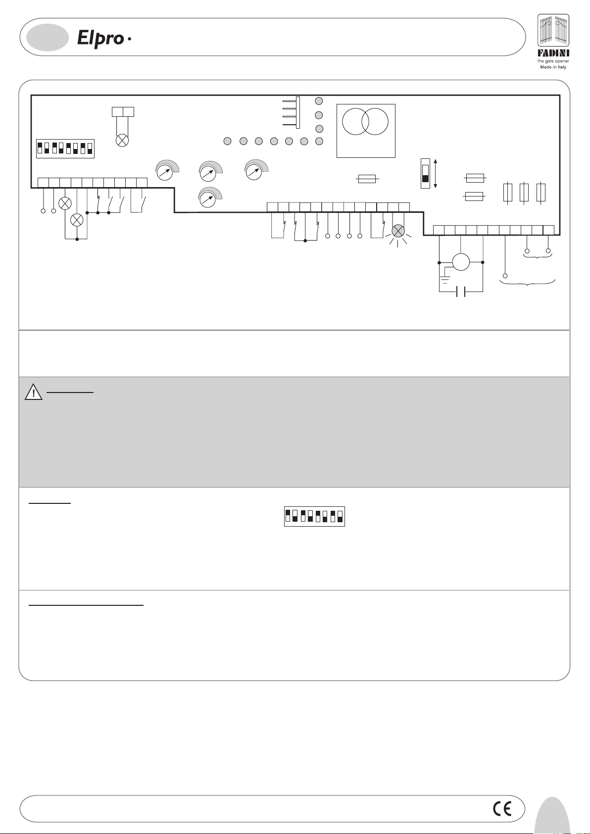
General description: The electronic control panel Elpro 70/3 Plus, new generation, is designed to operate the sliding gate operators MEC 200. Power supply is 230-400V single- and
three-phase. It is built in full compliance with the Low Voltage 2006/95/CE and Electro-Magnetic Compatibility Regulations 2004/108/EEC - 92/31/EEC. Fitting operations are recommended
to be carried out by a qualified technician in conformity to the existing safety standards. The manufacturing company declines any responsability for incorrect handling and applications;
also, it reserves the right to change or update the control panel any time.
Failure to follow the installation regalations may result in serious damages to properties and persons.
PLEASE NOTE:
- The control panel is fitted inside Mec 200.
- Make sure that the power supply to the electronic programmer is 230V ±10% or 400V ±10%.
- Make sure that the power supply to the Electric Motor is 230V ±10% or 400V ±10%.
- For distances of over 50 metres we recommend using electric cables with bigger sections.
- Fit the mains to the control panel with a 0.03A high performance circuit breaker.
- Use 1.5 mm2 section wires for voltage supply, electric motor and flashing lamp. Maximum recommended distance 50 m.Use 1 mm2 section wires for
limit switches, photocells, push-buttons/key-switch and accessories.
- Bridge terminals 11 and 12 if no photocells are required.
- Bridge terminals 5 and 6 if no key- or push-button switches are required.
N.W: To fit extra accessories such as lights, CCTV etc. use only solid state relays to prevent damages to the microprocessor.
Dip-Switch:
1= ON Photocells. Stop on opening
2= ON Radio. No reversing on opening
3= ON Automatic closing
1
DIP-SWITCH
2
3
ON
OFF
6
8
4
7
5
4= ON Preflashing activated
5= ON Radio.Step by step, stop in between
6= ON Deadman Control (Dip 4=OFF n Dip 3=OFF)
7= ON No light during dwell time
8= OFF. Blank
In case of failure of the panel:
- Make sure that the power supply to the electronic programmer is 230V ±10% or 400V ±10%
- Make sure that the power supply to the Electric Motor is 230V ±10% or 400 V ±10%
- For distances of over 50 metres we recommend using electric cables with bigger sections.
- Check fuses
- Check photocells if contacts are normally closed
- Check all NC contacts
- Check that no voltage drop has occurred from the control panel to the electric motor
Drwg. No.
4138
5
Page 3

GB
®
70/3
LOW VOLTAGE ELECTRICAL CONNECTIONS
PLUS
SINGLE-/THREE-PHASE FOR SLIDING GATE OPERATORS MEC 200
Photocell:
11 12
PHOTOCELL
CONTACT
Push Button Switch:
INDICATION
LAMP CLOSE
48V max 3A
Radio Contact:
- Open/Close (Standard)
- Travel reversing on pulsing
- Step by step
24V 3W Indication Light:
18 19
4
3
INDICATION
LAMP OPEN
48V max 3A
POWER SUPPLY 24V
5
6
7
STOP
CLOSE
8
OPEN
COMMON
9
COMMON
+24V
DIP-SWITCH 1:
ON: Photocells stop gate while opening,
reverse it on closing once obstacle is
removed
OFF: Photocells do not stop gate while
1
opening, reverse it on closing in
case of an obstacle
10
LIGHT
CONTACT
RADIO
DIP-SWITCH 2 and 5 (NEVER set BOTH of them to ON at the same time):
ON: Gate is not reversed while opening
OFF: Any pulse reverses the gate
2
Light ON = Open gate
Light OFF = Closed gate
Flashing (fast) 0.5s = Closing gate
Flashing (normally) 1s = Opening gate
Flashing (slowly) 2s = gate is stopped
Limit switch:
13
14
LIMIT SWITCH
CLOSE
ON: Step by step. Stop in between
OFF: Standard operating mode
5
15
COMMON
LIMIT SWITCH
OPEN
Electric lock:
Set the T4 Trimmer Time to the lowest value
The electric lock is excited for 2 seconds
12
POWER SUPPLY 24V
16
17
Safety SwitchRadio Power Supply
Courtesy light:
Connect a 24VAC Modular Relay
T4 Trimmer Time from 2s to 255s)
(
to operate a 230V lamp
202221
16
17
6
Drwg. No.
4138
Page 4

GB
70/3
ELECTRICAL POWER CONNECTIONS
Single- (230V) and
Three-phase (400V) Motors:
PLUS
16µF CAPACITOR
SINGLE-/THREE-PHASE FOR SLIDING GATE OPERATORS MEC 200
25 2624
W
V
M
230/400V
THREE-PHASE MOTOR
U
±10% 50Hz
-
+
T1 MOTOR RUN TIME
OPEN / CLOSE
from 5 to 150s
T2 DWELL TIME
from 5 to 150s
W
25 2624
COMMON
V
M
±10% 50Hz
230V
SINGLE-PHASE
MOTOR
U
®
+
-
Flashing lamp:
Power supply:
230V
22
23
230V MAX 25W
400V
OPERATING MODES
Automatic / Semiautomatic:
Pedestrian Opening:
Trimmer T3 from 3 to 30s.
It can be activated by any pulse (eg. by remote control) superior to 2s
DIP-SWITCH 4 and 7:
ON: Pre-flashing
OFF: No pre-flashing
4
27 22
LIVE
LIVE
RTS
±10% 50Hz
230V
SINGLE-PHASE
±10% 50Hz THREE-PHASE
400V
-
Dwell Time
T2
from 5 to 128s
-
Trimmer
T3
ON: Lamp is not operating during
Dwell Time. Automatic Mode.
OFF: It flashes during Dwell Time .
7
Automatic Mode.
2928
NEUTRAL
DIP-SWITCH 3
+
ON= Automatic Closing
OFF= No Automatic. Semi-automatic
3
closing by pulse
FADINI
l'apricancello
+
Hold on switched (Deadman) control:
DIP-SWITCH 6
ON= Deadman Control. Dip-switch 4=OFF
and Dip-switch 3=OFF
OFF= Standard Operations
6
Led Status Indication:
L1 = 230V 50Hz power supply. Alight
L2 = Photocells, if obstructed light goes off
L3 = Open. Alight whenever an Open pulse is given
L4 = Close. Alight whenever a Close pulse is given
L5 = Stop. It goes off on pulsing Stop
L6 = Radio. It goes on by pressing a transmitter button
L7 = Gate Status; it flashes on gate moving
L8 = Limit switch Close; off when gate is closed
L9 = Limit switch Open; off when gate is open
L10= It stays on for a time equal to the time set on T4 Trimmer
Drwg. No.
4138
7
Page 5

200
182
04-2009
260 280
110
I -
Prima dell'installazione da parte di personale tecnico qualificato, si consiglia di prendere visione del
Libretto Normative di Sicurezza che la Meccanica Fadini mette a disposizione.
GB -
Please note that installation must be carried out by qualified technicians following Meccanica Fadini's
Safety Norms Manual.
F -
L'installation doit être effectuée par un technicien qualifié suivant le manuel des Normes de Sécurité
de Meccanica Fadini.
D -
Vor der Montage durch einen Fachmann, wird es empfohlen die Anleitung zur Sicherheitsnormen, die
Meccanica Fadini zur Verfügung stellt, nachzulesen.
E -
Antes de la instalación por el personal técnico calificado, se recomienda leer detenidamente el Folleto
de la Reglamentación de Seguridad que la empresa Meccanica Fadini pone a su disposición.
NL -
Voordat de installatie door gekwalificeerd technisch personeel wordt uitgevoerd, wordt geadviseerd
om het boekje met veiligheidsvoorschriften dat Meccanica Fadini ter beschikking stelt door te lezen.
Direttiva 2003/108/CE
Smaltimento dei materiali
I
elettrici ed elettronici
VIETATO GETTARE NEI RIFIUTI
MATERIALI NOCIVI PER L’AMBIENTE
2003/108/CE Directive
for waste electrical and
GB
electronic equipments
DISPOSE OF PROPERLY
ENVIRONMENT-NOXIOUS MATERIALS
®
s.n.c.
Via Mantova, 177/A - 37053 Cerea (Verona) Italy - Tel. +39 0442 330422 r.a. - Fax +39 0442 331054
e-mail: info@fadini.net - www.fadini.net
La ditta costruttrice si riserva di apportare modifiche al presente libretto senza preavviso
 Loading...