

Page 1
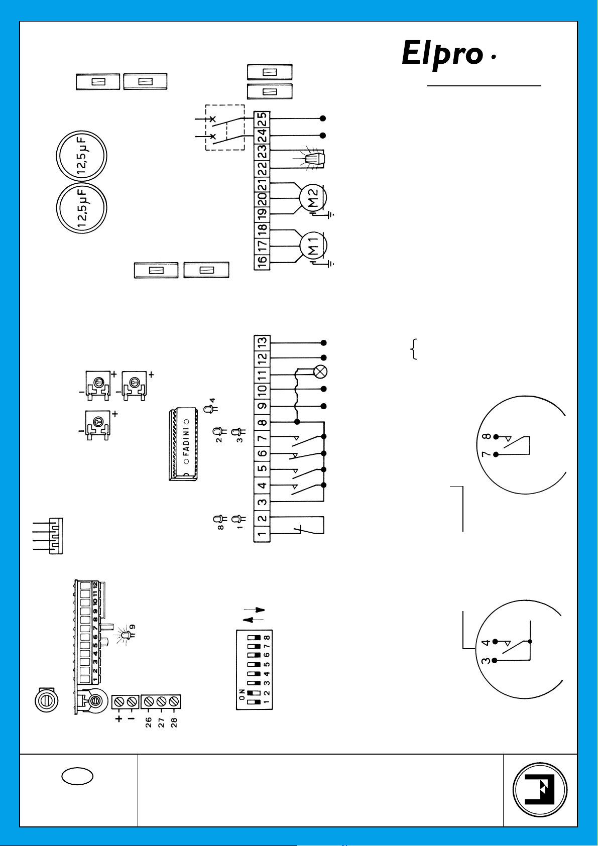
CAPACITORS
FUSE
630 mA
DWELL TIME
1 A FUSE
MOTOR RUN TIME
OPEN & CLOSE
CUT OFF SWITCH
BY COVER KNOB
2 AMP. FUSE TO PROTECT
THE ELECTRIC LOCK
OUTPUT
TERMINALS
No. 9-10
5 AMP .
FUSE
FUSE
630 mA
COMMON
COMMON
FOR SWING GATES
bpt
240 V SINGLE-PHASE
SUPPLY VOLTAGE
240 V - 25 W max. FLASHING LAMP
SINGLE-PHASE
ELECTRIC MOTORS
Max permitted load:
24 V OUTPUT A.C.
24 V INDICATOR GATE OPEN - 3 W max.
2 pairs photocells
1 radio receiver
23
CEI
NOTE WELL: For special applications, ie. to switch
on lights - CCTV etc., SOLID STATE RELAYS are
recommended to be used only. Standard relays
would affect the micro-processor.
RADIO CONTROL
PLUG-IN CARD SUPPORT
24 V OUTPUT
1st CHANNEL
1 A FUSE TO PROTECT
THE 24 V= OUTPUT
LEAF DELAY
TIMER CLOSE
MICROPROCESSOR
TERMINALS FOR THE
CONNECTIONS TO THE
PUSH BUTTONS PULIN 3
ON
DIP-SWITCH
OFF
VOLTAGE OUTPUT
ELECTRIC LOCK SUPPLY 12V A.C./ 24V D.C.
COMMON
RADIO CONTACT N.O.
STOP SWITCH N.C. CONTACT
CLOSE SWITCH N.O. CONTACT
OPEN SWITCH N.O. CONTACT
COMMON
N.C. CONTACT
PHOTOCELLS
PEDESTRIAN MODE
ONE PULSE OPENS
ONE GATE LEAF ONLY
REVERSE
RADIO CONTACT
ALL OPERATIONS
OPEN, CLOSE AND
PULSE TWICE
BOTH GATE LEAFS
CONSECUTIVELY TO OPEN
GB
Drwg. No.
2125
24 V. D.C.
OUTPUT
Should more pairs of photocells be required than
the recommended quantity, fit an auxiliary
NOTE WELL: THIS PANEL IS TESTED TO
OPERATE GATES ONLY THROUGH FADINI
ACCESSORIES. NO GUARANTEE FOR
ACCESSORIES OF OTHER MAKE OR SPECIAL
APPLICATIONS.
transformer outside the control box.
CONNECTION DIAGRAM
ELECTRONIC PROGRAMMER
FOR SINGLE-PHASE SWING GATES
Page 2

23
CEI
bpt
FEATURES OF THE ELECTRONIC PROGRAMMER FOR SWINGING GATES
All the electrical connections are to be made as per the following instructions and diagrams. Supply the terminals 24-25 with 240V- 50 Hz
single-phase voltage. The “Red LED” switches on and stays on as long as the board is properly supplied. Through the timer No. 9 you
can control the running time of the motor in both cycles, OPEN and CLOSE. Set it so that the running time of the motor is longer than the
actual travel of the gate; set the timer No. 8 - DWELL - ie. the interval between open and re-closing, so that you can meet the required
interval of time. The timer No. 7 - LEAF DELAY in "close" cycle - is to be set as follows: on to "-" (less) the delay is out of service; clockwise
on to "+" (more) the delay is operative.
- With the electric motor connected to terminals 19-20-21: the delay is operative in the "open" cycle, with a factory pre-set time.
- With the electric motor connected to 16-17-18: the delay is operative in "close" cycle and can be adjusted through the timer No. 7 on to
"less" or "more".
LOGIC OF THE ELECTRONIC PROGRAMMER: When a pulse is given, the flashing light switches on. After three seconds the motors start .
During the interval before re-closing, the light stays on. When the gates are fully re-closed, the light keeps on flashing for three more seconds
and then switches off automatically.
The 3 second interval (pre-flashing) which precedes the actual start of the motors can be eliminated by means of the DIP-SWITCH “A” No. 4.
LED No. 1: "OPEN". It switches on when the respective switch is activated.
LED No. 2: "CLOSE". It switches on when the respective switch is activated.
LED No. 3: "RADIO". It switches on whenever a pulse is given, either from remote control, keyswitch or push buttons.
LED No. 4: “STOP". Normally on. It switches off when the respective switch is activated.
LED No. 8: "PHOTOCELLS". Normally on. It switches off when the photocells are obstructed.
LED No. 9: It switches on when voltage is supplied.
DIP-SWITCH SETTING IN ELPRO 23 type "A"
N° 1 OFF = PHOTOCELLS. NO STOP IN OPEN CYCLE. REVERSE/CLOSE
N° 2 OFF = REMOTE CONTROL. REVERSE
N° 3 OFF = NO AUTOMATIC RECLOSING
N° 4 OFF = NO PRE-FLASHING
N° 5 OFF = REMOTE CONTROL. NO STOP AND HOLD AS LONG
AS BUTTON DOWN. IT OPENS STRAIGHT AWAY
N° 6 OFF = BOTH LEAFS ARE OPERATED
N° 7 OFF = S. R. P. OUT OF SERVICE
N° 8 OFF = LEAF DELAY OPEN CYCLE.
ONE STARTS BEFORE THE OTHER
LAMP ON = GATE OPEN
LAMP FLASHES SLOWLY = GATE OPENING
LAMP FLASHES FAST = GATE CLOSING
LAMP OFF = GATE CLOSED
1) It is advisable not to expose the control box directly to weather conditions; if mounted outside, a suitable enclosure is recommended to
protect it from sunshine and rain.
2) Bridge terminals 1 - 2 if you do not require any photocells.
3) Should two sets of photocells be required, these are to be series connected to terminals 1 - 2, contact normally closed.
N° 1 ON = STOP DURING OPEN CYCLE
N° 2 ON = NO REVERSE DURING OPEN CYCLE
N° 3 ON = AUTOMATIC RECLOSING
N° 4 ON = PRE-FLASHING
N° 5 ON = STOP AND HOLD AS LONG AS
THE BUTTON IS KEPT DOWN
N° 6 ON = PEDESTRIAN. ONE LEAF ONLY
GATES IN CLOSE POSITION
N° 7 ON = S. R. P. IN SERVICE
GATES IN CLOSE POSITION
N° 8 ON = NO LEAF DELAY
BOTH MOTORS START TOGETHER
4) Bridge terminals 6 - 8 if you do not require any keyswitch or push buttons.
5) Fit the mains to the control box with a high sensitivity, differential, magnetic-thermal switch, 0.03 Amps.
6) NOTE WELL
FAULT FINDING:
- Check supply voltage with a tester: it must be 240V, single-phase
- Check the high voltage fuses
- Check if the photocells contacts are normally closed
- Check voltage from the control box to the electric motor(s): power might have dropped
- Check the low voltage fuse
- The section of the electric cables to the motor(s) must not be less than 1.5 mm
* 24 V ~ output. Terminals 12-13. It can supply power for 2 pairs of photocells plus 1 radio receiver. Terminal 11 provides a power output
for a lamp. 24 V - 3 W max. Flashing lamp output. Terminals 22-23. Maximum available power 25 W max.
2
®
Page 3

23
CEI
bpt
FEA TURES AND TECHNICAL SPECIFICATIONS
"ELPRO 23” represents the latest state of the art technology for control panels. It is extremely versatile and can meet the most various
requirements.
It has the same functions as ELPRO 9 and incorporates additional advantages as follows: Stroke Reversing Pulse, Pedestrian Operating
Mode (where one leaf only can be operated allowing people to walk in/out), STOP and HOLD function by keeping the remote control button
pressed down).
Further improvements can be noted in the "ELPRO 23" panel:
- Addition of a 1 A fuse to the 24 V circuit as a protection for the accessories (remote control - photocells - etc.) which are connected to
the terminals 12 - 13 and for the panel itself in that it can prevent short circuit during installation.
- The pulse to the electric lock has an adjustable time so that the electric lock can be released with an anticipation of 100 mS before the
gate starts moving.
- A 24V 3W lamp indicates gate operations (Gate CLOSED = Lamp OFF - Gate in OPEN cycle = Lamp flashes slowly - Gate OPEN = Lamp
stays ON without flashing - Gate in CLOSE cycle = Lamp flashes fast).
- It provides a better switching intelligence design to enhance the reliability of the relays.
- The Motor Run Time is independent from the Leaf Delay Time in close cycle (the delay time is automatically added to the duration of the
opening time).
- The 8 DIP-switches can be arranged into any of the possible patterns to achieve the required operating modes without any risk of
interference with one another.
"STROKE REVERSING PULSE" and "S.1A.P.":
Set DIP switch No. 7 to ON. The "Stroke Reversing Pulse" (S.R.P.) is activated only with the gate in the CLOSE position. The pulse operates
the gate in the CLOSE direction first and then immediately reverses into OPEN (this will help the gate lock to release). All the other operations
will be performed in the standard way. No danger comes from the Stroke Reversing Pulse. This function remains in service with the panel
set to "Pedestrian Mode".
Set DIP switch No. 6 to ON for "Pedestrian Mode" (S.1A.P.), terminals 3-4. Only one leaf is operated when the OPEN button is pressed
down. Automatic reclosing. If the OPEN button is pressed twice in a row, both leafs are opened. The S.1A.P. function is activated only when
the gate is in the fully CLOSE position. The remote control always operates both gates, contact 7 - 8.
DIP-SWITCH SETTING IN ELPRO 23 type "A"
N° 1 OFF = PHOTOCELLS. NO STOP IN OPEN CYCLE. REVERSE/CLOSE
N° 2 OFF = REMOTE CONTROL. REVERSE
N° 3 OFF = NO AUTOMATIC RECLOSING
N° 4 OFF = NO PRE-FLASHING
N° 5 OFF = REMOTE CONTROL. NO STOP AND HOLD AS LONG
AS BUTTON DOWN. IT OPENS STRAIGHT AWAY
N° 6 OFF = BOTH LEAFS ARE OPERATED
N° 7 OFF = S. R. P. OUT OF SERVICE
N° 8 OFF = LEAF DELAY OPEN CYCLE.
ONE STARTS BEFORE THE OTHER
ADDITIONAL FEATURES:
- OPEN and CLOSE pulses to allow one cycle only in case a button is stuck down.
- “HOLD OPEN GATES” feature. The panel set on automatic reclosing mode; it is possible to connect a switch or timeclock to the OPEN
terminal to hold the gate open for the required period of time.
- Auxiliary 24 V D.C. 150 mA max. OUTPUT.
- In addition to the features which you already know and the LED indication outputs that are standard with the existing panel, the following
additional features have been included with the new unit:
1 No. 5A-150 mA change-over contact. This can be used to connect signal lights such as traffic lights (for instance you can connect
two external lamps 1 red, 1 green).
4 Nos. N.O. solid state switch outputs designed to allow the connection of 24 V D.C. relay coils without protecting diodes.
The 4 switches are excited individually to indicate the following gate status: OPENING - OPEN - CLOSING - CLOSED.
12 V A.C. / 24 V D.C. electric lock output. The duration of the pulse to the lock can be adjusted by means of a potentiometer.
12 V D.C./A.C. relay with N.O. contacts for the connection of an Intercom Entry System.
N° 1 ON = STOP DURING OPEN CYCLE
N° 2 ON = NO REVERSE DURING OPEN CYCLE
N° 3 ON = AUTOMATIC RECLOSING
N° 4 ON = PRE-FLASHING
N° 5 ON = STOP AND HOLD AS LONG AS
THE BUTTON IS KEPT DOWN
N° 6 ON = PEDESTRIAN. ONE LEAF ONLY
GATES IN CLOSE POSITION
N° 7 ON = S. R. P. IN SERVICE
GATES IN CLOSE POSITION
N° 8 ON = NO LEAF DELAY
BOTH MOTORS START TOGETHER
®
Page 4

200
23
FOR SWING GATES
CEI
280
260
182
®
ADDITIONAL
CARD
bpt
140
COVER KNOB
CUT OFF SWITCH
8 WAY
DIP-SWITCH
TECHNICAL DATA
- Supply Voltage 240 V - 50 Hz
- Voltage Output 240 V - 25 Hz
- Low Voltage Output 24 V - 10 W
- E.M. Power Output 1˙100 W
- Line Fuses 5 A
- Secondary Fuses 0.5 A
- Command Open - Stop - Close Other functions
- Dimensions of the Container 280x200x140 mm
- IP Standards IP 437
Open Contact Relay
Approval Mark IMQ - -S-S-10 A - 240 V
- Capacitor 12 µF - 400 V
Transformer
- Power 20 VA
- Magnetic Core 1.5 W / Thickness 0.50
- Supply Voltage 0 - 240 V
- Output 0 - 18 - 24 V
- Working Frequency 50 - 60 Hz
- Insulation 4 Kv x 1’
+
CUT OFF SWITCH
BY COVER KNOB
GB
Drwg. No.
2125
AUTOMATIC GATE MANUFACTURERS
Via Mantova, 177/A - 37053 Cerea (Verona) Italy
®
Tel. 0442 330422 r.a. - Fax 0442 331054
s.n.c.
e-mail: info@fadini.net - www.fadini.net
®
Made in Italy
Page 5

23
CEI
FOR SWING GATES
bpt
CONNECTION DIAGRAM AND FEATURES OF THE ADDITIONAL CARD
COMMON +24 V
2 AMP. FUSE
CLOSING
CLOSE
OPEN
RED
SUPPLY VOLTAGE
240 V - 50 Hz
OPENING
RELAYS FITTED WITH 24 V D.C.
150 mA max. COILS ARE RECOMMENDED
10) ELECTRIC LOCK TIME ADJUSTMENT
CLOCKWISE = MORE
ANTI-CLOCKWISE = LESS
11) GATE STATUS INDICATION LEDs
1-LED OPENING / 2-LED OPEN / 3-LED CLOSE / 4-LED CLOSING / 5-LED TRAFFIC LIGHTS
12) 12V RELAY TO CONNECT ONE INTERCOM UNIT
13) CONNECTORS
14) SWITCH TO CHANGE VOLTAGE TO ELEC.LOCK FROM 12 V A.C. - TO 24V D.C.
15) LINK DOWN, PULSE TO THE 12 V A.C. ELECTRIC LOCK
LINK UP, PULSE TO THE 24V D.C. ELECTRIC LOCK
16) RELAY FOR THE GATE LOCK
17) RELAY FOR THE TRAFFIC LIGHTS
PURE CONTACT N.O. 1 AMP.
12 V DC/AC COIL
GREEN
COMMON
N.O.
N.C.
The green lamp is
on only with open
gates and motors off
PIN TO PREVENT WRONG
FITTING OF THE CARD
ON TO THE PC BOARD
AUDIO/VIDEO
CONNECTION
For audio/video connection 12 V AC Lock Output connect to terminals 8 & 9 plug in additional card. Connect to main terminals
7 & 8 radio/common from additional card 6 & 7 relay contact.
GB
CONNECTION DIAGRAM
AND FEATURES OF THE
Drwg. No.
2125
ADDITIONAL DIAGRAM
®
Page 6

ADDITIONAL FEATURES:
- OPEN and CLOSE pulses to allow one cycle only in case a button is stuck down.
- “HOLD OPEN GA TES ” feature. The panel set on automatic reclosing mode; it is possible
to connect a switch or timeclock to the OPEN terminal to hold the gate open for the required
period of time.
- Auxiliary 24 V D.C. 150 mA max. OUTPUT.
- In addition to the features which you already know and the LED indication outputs that
are standard with the existing panel, the following additional features have been included
with the new unit:
1 No. 5A-150 mA change-over contact. This can be used to connect signal lights such
as traffic lights (for instance you can connect two external lamps 1 red, 1 green).
4 Nos. N.O. solid state switch outputs designed to allow the connection of 24 V D.C.
relay coils without protecting diodes.
The 4 switches are excited individually to indicate the following gate status: OPENING OPEN - CLOSING - CLOSED.
12 V A.C. / 24 V D.C. electric lock output. The duration of the pulse to the lock can be
adjusted by means of a potentiometer.
12 V D.C./A.C. relay with N.O. contacts for the connection of an Intercom Entry System.
23
FOR SWING GATES
bpt
CEI
ADDITIONAL
CARD
1A
1A
240 Volts
50 Hz
5A
630 mA
CUT OFF SWITCH
BY COVER KNOB
GB
Drwg. No.
2125
2A
1716 191813121110987654321 2120 2322 2524
VIEW OF THE P.C. BOARD
WITH COMPONENTS
630 mA
5A
®
 Loading...