

Page 1

pag. 1,2,3,4
®
LIBRETTO DI ISTRUZIONI
I
PROGRAMMATORE A MICROPROCESSORE
MONOFASE PER SCORREVOLE GIRRI 130
GB
SINGLE-PHASE CONTROL PANEL WITH
MICROPROCESSOR FOR GIRRI 130 SLIDING GATE OPERATOR
F
D
EINPHASIGE STEUERUNG MIT MIKROPROZESSOR
FÜR SCHIEBETORANTRIEB GIRRI 130
15
15
NOTICES D'INSTRUCTION
15
MONOPHASE POUR PORTAIL
COULISSANT GIRRI 130
15
PLUS
INSTRUCTIONS
PLUS
PLUS
ANLEITUNG
PLUS
- FUNZIONE PASSO PASSO
- APERTURA PEDONALE
- UOMO PRESENTE
- SPIA DI SEGNALAZIONE DELLO STATO DELL'AUTOMAZIONE
- OROLOGIO
- STEP BY STEP OPERATIONS
- PEDESTRIAN OPENING
- HOLD-ON SWITCHED (DEADMAN) CONTROL
- GATE STATUS INDICATION
- TIME CLOCK OPTION
- FONCTION PAS A PAS
- OUVERTURE PIETONS
- FONCTION HOMME MORT
- SIGNALISATION DE L'ETAT DE L'AUTOMATION PAR LED
- FONCTION HORLOGE
- SCHRITT-IMPULS-FUNKTION
- GEHTÜRFUNKTION
- TOTMANN-BEDIENUNG
- AUTOMATION-STATUS ANZEIGELAMPE
- UHR-FUNKTION
page 1,5,6,7
page 1,8,9,10
Seite 1,11,12,13
FOLLETO DE INSTRUCCIONES
E
PROGRAMADOR CON MICROPROCESADOR
MONOFASICO PARA VERJA DESLIZANTE GIRRI 130
NL
MICROPROCESSOR VOOR SCHUIFHEKOPENER GIRRI 130
Dis. N.
4136
EENFASE PROGRAMMEERINRICHTING MET
15
15
PLUS
HANDLEIDING
PLUS
- FUNCIONAMIENTO PASO A PASO
- ABERTURA PARA PASO DE PEATONES
- HOMBRE PRESENTE
- LÁMPARA TESTIGO QUE SEÑALA ELE ESTADO DEL AUTOMATISMO
- FUNCIÓN RELOJ
- STAP-VOOR-STAP FUNCTIE
- VOETGANGERSDOORGANG
- DODEMANSFUNCTIE
- SIGNALERINGSLAMP AUTOMATISERINGSSTATUS
- KLOKFUNCTIE
Via Mantova, 177/A - 37053 Cerea (Verona) Italy - Tel. +39 0442 330422 r.a.
®
Fax +39 0442 331054 - e-mail: info@fadini.net - www.fadini.net
s.n.c.
pág. 1,14,15,16
pag. 1,17,18,19
1
Page 2
GB
15
PLUS
SINGLE-PHASE CONTROL PANEL WITH
MICROPROCESSOR FOR GIRRI 130 SLIDING GATE OPERATOR
®
230V
M
COMMON
PHOTOCELLS
COMMON
OPEN
CLOSE
STOP
RADIO CONTACT
LIMIT SWITCH CLOSE
LIMIT SWITCH COMMON
LIMIT SWITCH OPEN
INDICATION LAMP 24V max 3W
24V OUTPUT (max. load:
2 PAIRS PHOTOCELLS
1 RADIO RECEIVER)
1
2
3
74
85
96
10
11
12
13
-
MOTOR RUN
T1
TIME
OPEN/CLOSE
from 2 up to
255s
L1
L2
L3
L4
L5
L6
L7
L8
L9
+
ELPRO 15 PLUS
+
-
DWELL
T2
TIME from 2
up to 255s
DIP-SWI TCH
14567823
ELPRO 15 plus
MICROPROCESSOR
-
COURTESY
T3
LIGHT from 2
up to 255s
2324
EXT CAPACITOR
2122
230V max 100W
COURTESY LIGHT
+
ON
OFF
-
PEDESTRIAN
T4
OPENING
from 3 up
to 30s
+
-
MOTOR
T5
TORQUE from
40% to 100%
RADIO PLUG-IN
CARD
CONNECTOR
PULIN 3
27
26
28
3
20μF
+
19
20
VOLTAGE SUPPL
SINGLE-PHASE
230V 50Hz
Y
F3 Fuse=315mA
F1 Fuse=5A
230V Mains
18
17
FLASHING LAMP
230V 25W max
Transformer
Protection
TRANSFORMER
16
14
15
MOTOR
ELECTRIC
SINGLE-PHASE
F2 Fuse=5A
230V Mains
F4 Fuse=630mA
24V Protection
230V ±10% 50Hz
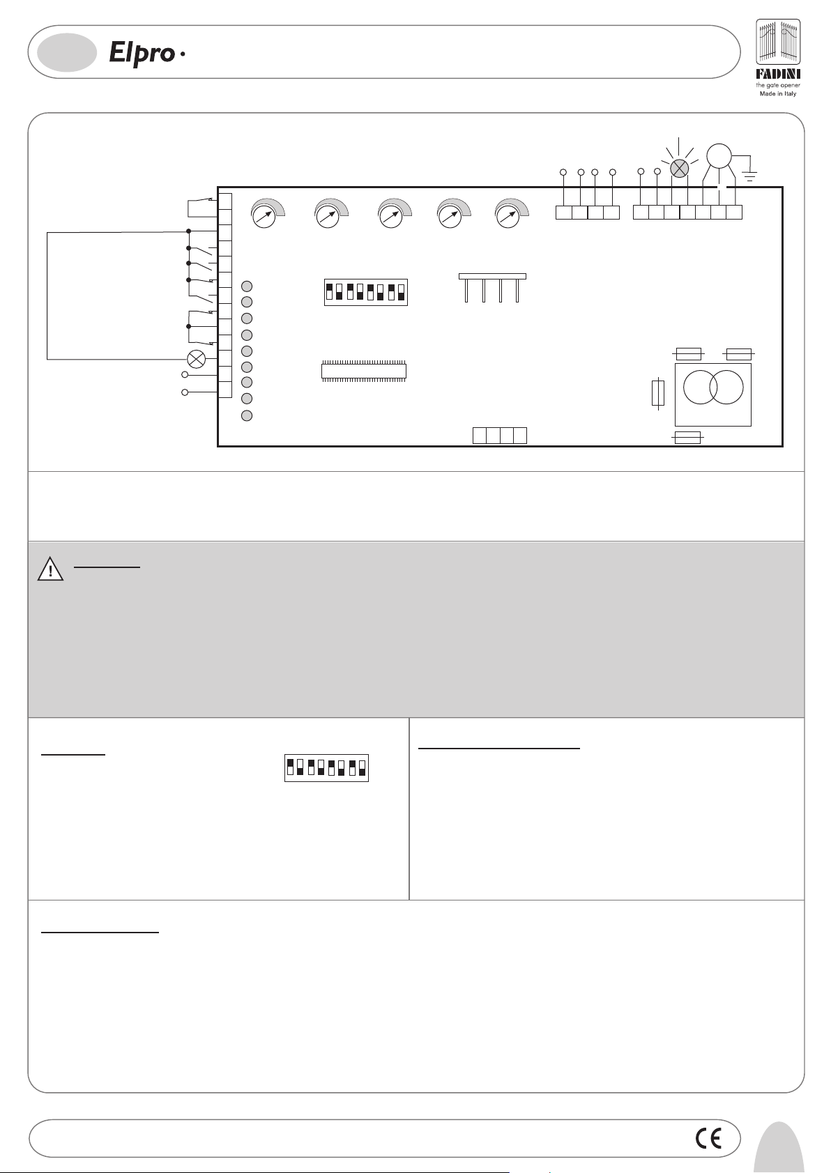
General description: The electronic control panel Elpro 15 Plus, new generation, is designed to operate the sliding gate operator Girri 130. Power supply is 230V 50Hz singlephase. Built in full compliance with 2006/95/CE Low Voltage and 2004/108/EEC - 92/31/EEC Electro-Magnetic Compatibility Regulations. Fitting operations are recommended
by a qualified technician in conformity to the existing safety standards.The manufacturing company declines any responsability for incorrect handling and application; also,
it reserves the right to change or update the control panel any time. Failure to follow installation regalations may result in serious damage to property and persons.
PLEASE NOTE:
- The control panel is fitted inside Girri 130.
- Make sure that the power supply to the electronic programmer is 230V ±10%
- Make sure that the power supply to the Electric Motor is 230V ±10%
- For distances of over 50 metres we recommend using electric cables with bigger sections.
- Fit the mains to the control panel with a 0.03A high performance circuit breaker.
- Use 1.5mm2 section wires for voltage supply, electric motor and flashing lamp. Maximum recommended distance 50m.
Use 1mm2 section wires for limit switches, photocells, push-buttons/key-switch and accessories.
- Bridge terminals 1 and 2 if no photocells are required.
- Bridge terminals 3 and 6 if no key- or push-button switches are required.
N.W: To fit extra accessories such as lights, CCTV etc. use only solid state relays to prevent damages to the microprocessor.
Dip-Switch:
DIP-SWI TCH
1= ON. Photocells. Stop while opening
2= ON. Radio. No reversing while opening
3= ON. Automatic closing
1456782
3
4= ON. Preflashing activated
5= ON. Radio. Step by step. Stop in between
6= ON. Dead Man Control (Dip 4=OFF and Dip 3=OFF)
7= ON. No lamp on during dwell time
8= OFF. No function
Led Status Indication:
L1= 230V 50Hz power supply. Alight
L2= Photocells, if obstructed light goes off
L3= Open. Alight whenever an Open pulse is given
L4= Close. Alight whenever a Close pulse is given
L5= Stop. It goes off on pulsing Stop
L6= Radio. It goes on by pressing a transmitter button
L7= Gate Status; it flashes on gate opening
L8= Limit switch Close; off when gate is closed
L9= Limit switch Open; off when gate is open
Drwg. No.
4136
ON
OFF
In case of failure of the panel:
- Make sure that the power supply to the electronic programmer is
230V ±10%
- Make sure that the power supply to the Electric Motor is 230V ±10%
- Check fuses
- Check photocells if contacts are normally closed
- Check that no voltage drop has occurred from the control panel to
the electric motor
5
Page 3

®
GB
15
LOW VOLTAGE ELECTRICAL CONNECTIONS
PLUS
SINGLE-PHASE CONTROL PANEL WITH
MICROPROCESSOR FOR GIRRI 130 SLIDING GATE OPERATOR
Photocells and Safety Edge:
2
1
PHOTOCELLS
AND SAFETY EDGE
Button switch:
3
COMMON
Radio Contact:
- Open/Close (Standard)
- Travel reversing on pulsing
- Step by step
Push Button Switch Pulin 3:
4
OPEN
12 13
5
CLOSE
24V (500 mA) OUTPUT (MAX. LOAD:
2 PAIRS PHOTOCELLS
1 RADIO RECEIVER)
6
STOP
3
7
COMMON
28
26
27
COMMON
CONTACT
RADIO
3
Led to indicate status of
Open - Stop - Close switches
DIP-SWITCH 1:
ON: Photocells stop gate while opening,
reverse it once obstacle is removed on closing
OFF: Photocells do not stop gate while
1
opening, reverse it in case of an
obstacle on closing
Limit switch:
DIP-SWITCH 2 and 5 (NEVER set BOTH of them ON at the same time):
ON: Gate is not reversed while opening
OFF: Any pulse reverses the gate
2
ON: Step by step. Stop in between
OFF: Standard operating mode
5
8
LIMIT SWITCH
CLOSE
10
9
COMMON
LIMIT SWITCH
OPEN
24V 3W Indication Light:
ELECTRICAL POWER CONNECTIONS
Capacitor and Single-phase Motor:
Flashing lamp 230V max 25W:
Power supply:
19
20
3
EXT Capacitor
20μF(fitted)
18
POWER SUPPLY
230V ±10% 50Hz
SINGLE-PHASE
Light ON = Open gate
11
Light OFF = Close gate
Flashing (fast) 0.5s= Closing gate
Flashing (normally) 1s= Opening gate
Flashing (slowly) 2s= gate is stopped
±10% MOTOR
230V
M
COMMON
2324
17
161415
DIP-SWITCH 4 and 7:
ON: Pre-flashing
OFF: No pre-flashing
4
T1
+
-
MOTOR RUN TIME
OPEN/CLOSE
from 2 up to 255s
ON: Lamp is not operating during
Dwell time. Automatic mode.
OFF: It flashes during Dwell Time.
7
Automatic Mode.
T2
-
DWELL TIME
from 2 up to 255s
Courtesy Light 230V max 100W:
T5
+
from 40% up to 100%
-
TORQUE
22 21
MOTOR
+
from 2s up to 255s
FADINI
l'apricancello
-
Trimmer T3
+
6
Drwg. No.
4136
Page 4

OPERATING MODES
GB
15
PLUS
SINGLE-PHASE CONTROL PANEL WITH
MICROPROCESSOR FOR GIRRI 130 SLIDING GATE OPERATOR
®
Automatic / Semiautomatic:
Automatic Operation: any pulse opens the gate, the gate stays open
as long as the Dwell time expires as set by T2 trimmer, then it closes
automatically, no pulsing is required.
Pedestrian Opening:
Trimmer T4
+
-
from 3 to 30s. It can be activated
by any pulse (eg. by remote control)
superior to 2s
Hold on switched (Deadman) control:
Open and Close operations are achieved "by holding a switch on" (no relay
self-holding is involved) therefore a phisical attendance is required to keep
the gate opening or closing until either the button or key is released.
Time clock
installation:
How it works: Set the clock to the required times. On the pre-set time the gate is automatically opened and held
open. Any further pulsing (even by remote control) is not accepted by the system until the time pre-set by the
clock has expired. On expiring and after the pre-set dwell time the gate is closed automatically.
T4 trimmer on to zero, Dip-Switch 3=ON.
DIP-SWITCH No.3=ON Automatic Closing
Semi-automatic Operation: any pulse opens the gate that stays open.
A second pulse to Close is required for the gate to close.
3
4
COMMON
DIP-SWITCH N°6=ON
ON= Deadman Control. Dip-switch 4=OFF
and Dip-switch 3=OFF
OFF= Standard Operations
6
OPEN
DIP-SWITCH N°3
External Time Clock
43
COMMON
OPEN
ON= Automatic Closing
OFF= No Automatic. Semi-
3
automatic closing by pulse
COMMON
+
-
Pedestrian Trimmer T4
set on to zero
ON= Automatic Closing
OFF= No Automatic. Semi-automatic
3
closing by pulse
NO
Drwg. No.
4136
7
Page 5

I -
Prima dell'installazione da parte di personale tecnico qualificato, si consiglia di prendere visione del
Libretto Normative di Sicurezza che la Meccanica Fadini mette a disposizione.
GB -
Please note that installation must be carried out by qualified technicians following Meccanica Fadini's
Safety Norms Manual.
F -
L'installation doit être effectuée par un technicien qualifié suivant le manuel des Normes de Sécurité
de Meccanica Fadini.
D -
Vor der Montage durch einen Fachmann, wird es empfohlen die Anleitung zur Sicherheitsnormen, die
Meccanica Fadini zur Verfügung stellt, nachzulesen.
E -
Antes de la instalación por el personal técnico calificado, se recomienda leer detenidamente el Folleto
de la Reglamentación de Seguridad que la empresa Meccanica Fadini pone a su disposición.
NL -
Voordat de installatie door gekwalificeerd technisch personeel wordt uitgevoerd, wordt geadviseerd
om het boekje met veiligheidsvoorschriften dat Meccanica Fadini ter beschikking stelt door te lezen.
07-2009
Direttiva 2003/108/CE
Smaltimento dei materiali
I
elettrici ed elettronici
VIETATO GETTARE NEI RIFIUTI
MATERIALI NOCIVI PER L’AMBIENTE
2003/108/CE Directive
for waste electrical and
GB
electronic equipments
DISPOSE OF PROPERLY
ENVIRONMENT-NOXIOUS MATERIALS
®
s.n.c.
Via Mantova, 177/A - 37053 Cerea (Verona) Italy - Tel. +39 0442 330422 r.a. - Fax +39 0442 331054
e-mail: info@fadini.net - www.fadini.net
La ditta costruttrice si riserva di apportare modifiche al presente libretto senza preavviso
 Loading...