

Page 1

pag. 1,2,3,4
LIBRETTO DI ISTRUZIONI
I
PROGRAMMATORE A MICROPROCESSORE
14
MONOFASE-TRIFASE PER CANCELLI A
DOPPIA ANTA SCORREVOLE
PLUS
- FUNZIONE PASSO PASSO
- UOMO PRESENTE
- APERTURA PEDONALE
- SPIA DI SEGNALAZIONE DELLO STATO DELL'AUTOMAZIONE
- POSSIBILITA' DI ESCLUDERE LAMPEGGIANTE IN PAUSA
- LUCE DI CORTESIA TEMPORIZZATA
- FUNZIONE OROLOGIO
GB
F
D
E
INSTRUCTIONS
14
CONTROL BOARD WITH MICROPROCESSOR
FOR BI-PARTING SLIDING GATES
MANUEL D'INSTRUCTION
14
PROGRAMMATEUR A MICROPROCESSEUR
MONOPHASE-TRIPHASE POUR PORTAILS
14
E-STEUERUNG MIT MICROPROZESSOR,
FÜR DOPPELFLÜGELSCHIEBETORE
FOLLETO DE INSTRUCCIONES
14
PROGRAMADOR DE MICROPROCESADOR
MONOFÁSICO-TRIFÁSICO PARA VERJAS DE
PLUS
SINGLE-/THREE-PHASE
PLUS
DOUBLES COULISSANTS
ANLEITUNG
PLUS
EIN-UND DREIPHASIG,
PLUS
DOBLE HOJA DESLIZANTE
- STEP BY STEP
- DEADMAN CONTROL
- PEDESTRIAN OPENING
- GATE STATUS INDICATION
- FLASHING LAMP ON DWELL TIME MADE SWITCH ABLE
-
TIMED COURTESY LIGHT
- TIME CLOCK FUNCTION
- FONCTION PAS-PAS
- HOMME MORT
- OUVERTURE AUX PIETONS
- LED DE SIGNALISATION POUR L'ETAT DE L'AUTOMATISATION
- EXCLUSION VOYANT CLIGNOTANT EN PAUSE
- LUMIERE DE COURTOISIE
- HORLOGE
- SCHRITT FÜR SCHRITT
- TOTMANNFUNKTION
- GEHTÜRFUNKTION
- AUTOMATION STATUS ANZEIGELAMPE
- AUSSCHALTBARE BLINKLEUCHTE WÄHREND DER PAUSEZEIT
- EINSTELLBARE DECKENLEUCHTE
- SCHALTUHRFUNKTION
- FUNCIÓN PASO-PASO
- HOMBRE PRESENTE
- ABERTURA PEATONAL
- INDICADOR DE SEÑALIZACIÓN ESTADO DE LA AUTOMACIÓN
- POSIBILIDAD DE DESCONECTAR DESTELLADOR EN PAUSA
- LUZ INTERIOR TEMPORIZADA
- FUNCIÓN RELOJ
page 1,5,6,7
page 1,8,9,10
Seite 1,11,12,13
pág. 1,14,15,16
NL
Dis. N.
GEBRUIKERSHANDLEIDING
14
PROGRAMMEERINRICHTING MET MICROPROCESSOR
EENFASE-DRIEFASE VOOR SCHUIFHEKKEN MET
Nyota 115 - n°1
PLUS
TWEE VLEUGELS
4198
- STAP-VOOR-STAP FUNCTIE
- DODEMANSFUNCTIE
- VOETGANGERSDOORGANG
- SIGNALERINGSLAMPJE VAN TOESTAND VAN AUTOMATISERING
- UITSCHAKELBAAR KNIPPERLICHT TIJDENS PAUZETIJD
- GETIMED COURTESY LIGHT
- KLOKFUNCTIE
Nyota 115 - n°2
Via Mantova, 177/A - 37053 Cerea (Verona) Italy - Tel. +39 0442 330422 r.a.
®
Fax +39 0442 331054 - e-mail: info@fadini.net - www.fadini.net
s.n.c.
pag. 1,17,18,19
MEC 200
1
Page 2
GB
14
PLUS
230V-400V SINGLE- /THREE-PHASE CONTROL BOARD
DESIGNED FOR AUTOMATIONS TO OPERATE BI-PARTING SLIDING GATES
®
26
27
PULIN 3
28
3
PLUG-IN
RADIO CARD
CONNECTOR
L3
L2
1
EDGES
L4
2
3
COMMON
CLOSE
OPEN
PHOTOCELLS AND SAFETY
LIMIT SWITCH
CLOSING
M2 MOTOR
D49
D50
DIP-SWITCH
4
2
1
3
5
Elpro 14 Plus vers. 1.4
L5
L8
STOP
L7
L9
74
85
96
RADIO
LIMIT SWITCH COMMON
LIMIT SWITCH CLOSING M1
LIMIT SWITCH
OPENING
M2 MOTOR
35
34 33
-
ON
-
OFF
6
8
7
-
-
L6
13
11
10
12
LIMIT SWITCH OPENING M1
24V max 3W
PILOT LIGHT
1 Radio receiver
2 pairs photocells
24V OUTPUT max load:
T4
EXT TIME (Electric lock and
courtesy light) from 2 to 255s
+
T3
PEDESTRIAN TIME
+
from 3 to 30s
T2
DWELL TIME
+
from 5 to 128s
T1
MOTOR RUN TIME
+
from 5 to 128s
RS
RS
16
W
230V COURTESY LAMP
OR 12V AC RELAY FOR
ELECTRIC LOCK
F6=630mA
24V protection
17
COMMON
V
M1
MOTOR
CAPACITOR
L1
L10
CAPACITOR
F5=1A Flashing
lamp protection
18
U
TRANSFORMER
30
31
W
COMMON
V
M2
MOTOR
ELPRO 14 PLUS
19
20
FLASHING LAMP
230V 25W max
230/400V
F4=630mA
transformer protection
230/400V
32
U
F3=10A Mains
21 22
LIVE
S
SINGLE-PHASE
230V 50Hz
POWER SUPPLY
LIVE
S
T
THREE-PHASE
400V 50Hz
POWER SUPPLY
F2=10A Mains
2322
±10%
R
±10%
F1=10A Mains
NEUTRAL
NEUTRAL
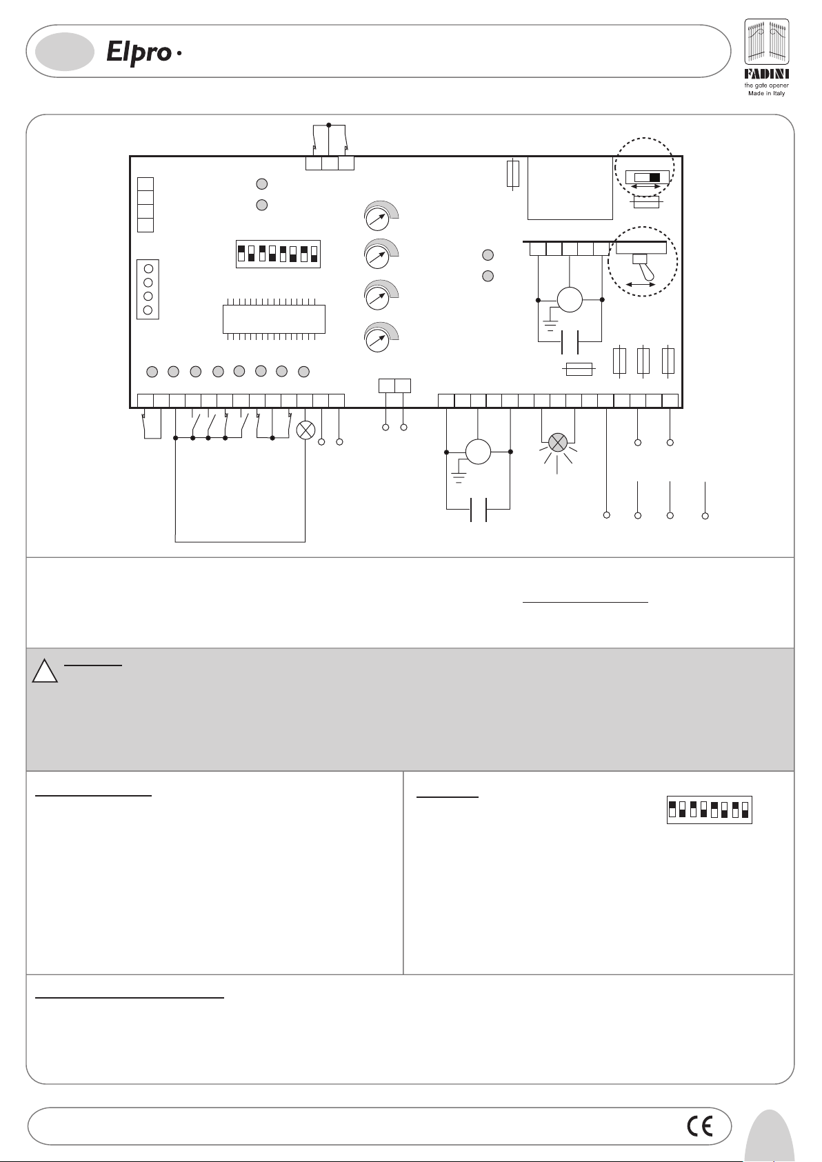
General Description: Elpro 14 Plus is an electronic board incorporating a microprocessor to control single- and three-phase operators for bi-parting sliding gates. Power
supply is 230V/400V ±10% 50Hz single-/ or three-phase. it is built in compliance with BT 93/68/CE Low Voltage norms and EMC 93/68/CE norms for the electro-magnetic
compatibility. Installation is recommended by a qualified technician in observance of the existing regulations.
Incorporated logic functions: automatic or semi-automatic
operating modes, pre-flashing/no pre-flashing options, reversing/non reversing options by remote control, electric lock output, pedestrian mode, hold-on-switched (deadman)
control, gate status indication by leds. The manufacturer declines any responsability for incorrect handling and applications, and reserves the right to update the instructions
and the control board without notice. Failure to observe the installation instructions may result into serious damages to persons and properties.
IMPORTANT:
- The control box is to be fitted in a sheltered, dry place inside a suitable enclosure
!
- Fit the mains to the control box with a 0.03 A high performance, magnetic-thermal circuit breaker
- Make sure that the power supplied to the board is 230V/400V ±10% 50Hz
- For the power supply and the flashing lamp use 1.5 mm
2
wires up to 50 m distance; for the limit switches and the accessories use 1mm
2
wires
- Bridge terminals 1 and 2 if no photocells are required
- Bridge terminals 3 and 6 if no key- or button-switches are required
- N.W: Should other applications be required such as light switching, CCTV, etc. use only solid state relays to prevent disturbances to the microprocessor.
1
DIP-SWI TCH
2
3
ON
OFF
6
8
4
7
5
Led Status Indication:
L1 = Power supply 230V/400V±10% 50Hz alight
L2 = Photocells. If obstructed the led goes off
L3 = Open. It illuminates when an Open pulse is given
L4 = Close. It illuminates when a Close pulse is given
L5 = Stop. It goes off when a Stop pulse is given
L6 = Radio. It illuminates when the remote control is pulsed.
L7 = Gate Status Indication. It flashes while gate is moving
L8 = Limit switch Closing M1 motor. Off when gate is closed
L9 = Limit switch Opening M1 motor. Off when gate is open
Dip-Switch:
1= ON Photocells stop gate on opening
2= ON Radio. No gate reversing on opening
3= ON Automatic Closing
4= ON Pre-flashing in service
5= ON Radio. Step by step, stop in between
6= ON Deadman Control (Dip 4=OFF and Dip 3=OFF)
7= ON Flashing lamp off on dwell time, automatic mode
8= OFF, blank
L10 = It stays alight as long as the time set on T4 Trimmer
D49= Limit switch Closing M2 motor. Off when gate is closed
D50= Limit switch Opening M2 motor. Off when gate is open
In case the automation fails to start:
- Check power supply to be 230V or 400V ±10% 50 Hz
- Check fuses
- Check photocells contacts to be normally closed
- Check all N.C. contacts
- Check that no voltage drop occurs between the board and the electric motor
Drwg. No.
4198
5
Page 3

GB
®
14
LOW VOLTAGE ELECTRICAL CONNECTIONS
Photocells and Safety Edge:
PLUS
230V-400V SINGLE- /THREE-PHASE CONTROL BOARD
DESIGNED FOR AUTOMATIONS TO OPERATE BI-PARTING SLIDING GATES
1
2
3
74
85
96
10
13
11
12
2
1
CONTACT FOR
PHOTOCELLS AND
SAFETY EDGE
Keyswitch:
Limit switch:
Radio Contact:
12 13
24V OUTPUT (MAX LOAD:
2 PAIRS PHOTOCELLS
1 RADIO RECEIVER)
4
3
5
OPEN NO
CLOSE NO
9
COMMON
10
6
STOP NC
LIMIT SWITCH
OPENING M1
COMMON
8
LIMIT SWITCH
CLOSING M1
- Open/Close (standard)
- Any new pulse reverses gate travel
- Step by step
DIP-SWITCH 1:
ON: Photocells stop gate on Opening and
reverse it on Closing once obstacle is removed
1
OFF: Photocells do not stop gate on Opening
and reverse it on Closing if obstructed
COMMON
LIMIT SWITCH
3
COMMON
CLOSING M2
35 34 33
LIMIT SWITCH
OPENING M2
7
RADIO NO
DIP-SWITCHES 2 & 5
(NEVER set both of them on to ON at the same time):
ON: No reversing on Opening
OFF: Reversing by any new pulse
2
ON: Step by step. Stop in between
OFF: Standard operating mode
5
Electric Lock:
Mechanical device to hold the gate in closed gate position.
Trimmer T4 to the lowest
Working Time: 2 seconds anticipation of 100ms on gate starting.
24V 3W Pilot Light for gate
movement indication:
Push Button unit Pulin3:
Courtesy light:
Connect a 12VAC relay (Trimmer T4 from 2s
to 255s) to operate a 230V lamp
RS
8
COMMON
Leds signalling the
commands Open-
Stop -Close
RS
RS
11
COMMON
RS
PILOT LIGHT 24V
3W max
12V AC, 15VA OUTPUT
ELECTRIC LOCK
POWER SUPPLY
Light On= Gate Open. Passage allowed
Light Off= Gate Closed. Passage not allowed
Flashing 0.5s (fast)= Gate Closing
Flashing 1s (normal)= Gate Opening
With external clock: 2 short flashes followed by a longer stop
3
28
27
26
-
+
Trimmer T4
EXT TIME (Electric lock and Courtesy Light)
from 2 to 255s
-
+
Trimmer T4
EXT TIME (Electric lock and Courtesy
Light) from 2 to 255s
to the lowest
6
Drwg. No.
4198
Page 4

GB
10
PLUS
230V-400V SINGLE- /THREE-PHASE CONTROL BOARD
DESIGNED FOR AUTOMATIONS TO OPERATE BI-PARTING SLIDING GATES
®
ELECTRIC POWER CONNECTIONS
Single- and three-phase motors:
Important:
Dipending on the site voltage requirements
it is absolutely necessary to set both
switches accordingly
230/400V
230V
400V
16
W
CAPACITOR
Flashing light:
Pre-flashing (Dip-Switch 4=ON): Once an Open
pulse is given, after 3 seconds M1 motor starts
Once the gate is fully closed, the lamp goes on
flashing for 3 more seconds.
Control board power supply:
Fit the mains to the control board with a 0.03A high
sensitivity, magnetic-thermal, differential circuit breaker
The board can be supplied 230V 50Hz ±10% Single-phase or
400V ±10% Three-phase. Both switches are to be set to the
required voltage.
17
COMMON
V
M1
MOTOR
18
U
Motor for
pedestrian
opening
19 20
230V
230/400V
FLASHING LIGHT
230V - 25W max
400V
211816 17 19 22 2320
30
W
31
V
COMMON
32
U
-
Trimmer T1
M2
MOTOR
CAPACITOR
DIP-SWITCH 4 and 7:
ON: Pre-flashing
OFF: No pre-flashing
4
ON: No flashing with the lamp on
Dwell time. Automatic mode
OFF: Flashing on Dwell time in Automatic mode option
7
21 22
LIVE
S
230V 50Hz ±10%
SINGLE-PHASE
MOTOR RUN TIME OPEN /
CLOSE FROM 5 TO 128s
2322
NEUTRAL
21 22
T
400V 50Hz
THREE-PHASE
T1
+
T2
+
-
Trimmer T2
DWELL TIME
from 5 to 128s
FADINI
l'apricancello
2322
LIVE
S
R
±10%
230 VOLT
400 VOLT
FUNCTIONS
Automatic / Semi-automatic:
Automatic cycle: On pulsing to Open the gate is operated to open, stops for a time equal
to the dwell time as pre-set with T2 trimmer, after this time the gate is automatically
operated to Close.
Semi-automatic Cycle: On pulsing to Open the gate is operated to Open and held in open
position. A new pulse is needed for the gate to close.
Deadman Control:
Open and Close operations are by "hold on switched" control ( no
relay self-holding is involved). The automation is to be attended and
the command unit is required to be held switched to achieve gate
operation. Any operation is stopped on releasing the button or key.
DIP-SWITCH 6
ON= Deadman Control Dip-switch 4=OFF
and Dip-switch 3=OFF
OFF= Normal operating mode
6
Pedestrian Opening:
With the gate in fully closed position, it is possible to open the gate for pedestrians by
pulsing to Open with Dip-Switch No.6=ON terminals 3-4:
- a first Open pulse operates Motor 1 to open
- a second pulse operates the other gate to Open
A pulse given to terminals 7 - 8 (Radio Contact) by the remote control always operates both gates.
Radio out of service on Dwell time in
Automatic Mode option:
ON: No gate travel reversing on Opening
OFF: Any new pulse reverses gate travel
2
In this Mode, any pulse given by Radio remote control during the dwell time in Automatic mode option does
not allow any operation with the system . DIP-SWITCH No.2=ON, No.3=ON and No.5=ON
ON= Automatic Closing
OFF= No Automatic Closing
3
+
-
Trimmer T2
DWELL TIME
from 5 to 128s
+
-
Trimmer T3
From 3 to 30 s activated by any
commanding pulse (even by remote
control), superior to 2s to M1 Motor
ON: Step by step Stop in between
OFF: Standard operating mode
5
DIP-SWITCH 3
ON= Automatic Closing
OFF= No automatic closing
Semi-automatic mode
3
Time clock:
Drwg. No.
How it works: Set the clock to the required time. On the set time the gate is operated to open and held open. No
other operations can be achieved (not even by remote control) until the time set on the clock has expired. On
expiring of the clock time and after the dwell time of the system, the gate is automatically operated to to close.
Trimmer T3 is to be set on to zero, Dip-Switch No. 3=ON
+
-
Trimmer T3
T3 Trimmer. Pedestrian
to zero value
DIP-SWITCH No.3=ON Automatic Closing
ON= Automatic Closing
OFF= No automatic closing.
3
Semi-automatic option
4198
COMMON
43
OPEN
NO
COMMON
7
Page 5

200
182
3-2007
260 280
110
I -
Prima dell'installazione da parte di personale tecnico qualificato, si consiglia di prendere visione del
Libretto Normative di Sicurezza che la Meccanica Fadini mette a disposizione.
GB -
Please note that installation must be carried out by qualified technicians following Meccanica Fadini's
Safety Norms Manual.
F -
L'installation doit être effectuée par un technicien qualifié suivant le manuel des Normes de Sécurité
de Meccanica Fadini.
D -
Vor der Montage durch einen Fachmann, wird es empfohlen die Anleitung zur Sicherheitsnormen, die
Meccanica Fadini zur Verfügung stellt, nachzulesen.
E -
Antes de la instalación por el personal técnico calificado, se recomienda leer detenidamente el Folleto
de la Reglamentación de Seguridad que la empresa Meccanica Fadini pone a su disposición.
NL -
Voordat de installatie door gekwalificeerd technisch personeel wordt uitgevoerd, wordt geadviseerd
om het boekje met veiligheidsvoorschriften dat Meccanica Fadini ter beschikking stelt door te lezen.
Direttiva 2003/108/CE
Smaltimento dei materiali
I
elettrici ed elettronici
VIETATO GETTARE NEI RIFIUTI
MATERIALI NOCIVI PER L’AMBIENTE
2003/108/CE Directive
for waste electrical and
GB
electronic equipments
DISPOSE OF PROPERLY
ENVIRONMENT-NOXIOUS MATERIALS
®
s.n.c.
Via Mantova, 177/A - 37053 Cerea (Verona) Italy - Tel. +39 0442 330422 r.a. - Fax +39 0442 331054
e-mail: info@fadini.net - www.fadini.net
La ditta costruttrice si riserva di apportare modifiche al presente libretto senza preavviso
 Loading...