

Page 1
pag. 1,2,3,4
®
I
GB
F
D
LIBRETTO DI ISTRUZIONI
12
12
NYOTA 115 SLIDING GATE OPERATOR
NOTICES D’INSTRUCTION
12
OUVRE-PORTAIL COULISSANT NYOTA 115
12
SCHIEBETORANTRIEBE NYOTA 115
PLUS
MONOFASE PER
SCORREVOLE NYOTA 115
INSTRUCTIONS
PLUS
SINGLE-PHASE FOR
PLUS
MONOPHASE POUR
ANLEITUNG
PLUS
EINPHASIG FÜR
- FUNZIONE PASSO PASSO - UOMO PRESENTE
- APERTURA PEDONALE - LUCE DI CORTESIA
- DIAGNOSTICA A LED LUMINOSI
- SPIA DI SEGNALAZIONE DELLO STATO DELL’AUTOMAZIONE
- FUNZIONE OROLOGIO
- STEP BY STEP OPERATIONS - HOLD-ON SWITCHED (DEADMAN) CONTROL
- PEDESTRIAN OPENING - COURTESY LIGHT
- FAULT INDICATION BY LEDs
- GATE STATUS INDICATION
- TIME CLOCK OPTION
page 1,5,6,7
- FONCTION PAS-PAS - HOMME MORT
- OUVERTURE PIETON - LAMPE D’ECLAIRAGE
- DIAGNOSE A LED VOYANT A DIODE
- SIGNALISATION DE L’ETAT DE L’AUTOMATION PAR LED
- FONCTION HORLOGE
page 1,8,9,10
- SCHRITT-IMPULS-FUNKTION - TOTMANN-BEDIENUNG
- GEHTÜRFUNKTION - DECKENLEUCHTE
- DIAGNOSE-LED
- AUTOMATION-STATUS ANZEIGELAMPE
- UHR-FUNKTION
Seite 1,11,12,13
E
NL
Dis. N.
4086
FOLLETO DE INSTRUCCIONES
12
VERJAS DESLIZANTES NYOTA 115
12
SCHUIFHEKKEN NYOTA 115
PLUS
MONOFASICO PARA
HANDLEIDING
PLUS
EENFASE VOOR
- FUNCIONAMIENTO PASO A PASO - HOMBRE PRESENTE
- ABERTURA PARA PASO DE PEATONES - LUZ AUXILIAR
- DIAGNOSTICO POR MEDIO DE LED LUMINOSOS
- LÁMPARA TESTIGO QUE SEÑALA ELE ESTADO DEL AUTOMATISMO
- FUNCIÓN RELOJ
- STAP-VOOR-STAP FUNCTIE - DODEMANSFUNCTIE
- VOETGANGERSDOORGANG - SIGNALERINGSLAMP
- DIAGNOSTIEK MET LICHTGEVENDE LEDS
- SIGNALERINGSLAMP AUTOMATISERINGSSTATUS
- KLOKFUNCTIE
Via Mantova, 177/A - C.P. 126 - 37053 Cerea (Verona) Italy - Tel. +39 0442 330422 r.a.
®
Fax +39 0442 331054 - e-mail: info@fadini.net - www.fadini.net
s.n.c.
pág. 1,14,15,16
pag. 1,17,18,19
1
Page 2
GB
PULIN 3
L3
L2
+
-
R65 R64 R63 R62
MOTOR RUN TIME
OPEN/CLOSE
from 2 up to 128s
L4
-
DWELL TIME
from 2 up to 128s
3
L5
TRIMMER
+
-
12
28
26
27
L6
L7
+
COURTESY LIGHT
from 2 up to 255s
L8
PLUS
L9
+
-
PEDESTRIAN OPENING
from 3 up to 30s
SINGLE-PHASE FOR NYOTA 115 SLIDING GATE OPERATOR
RADIO
14567823
PLUG-IN
CARD
CONNECTOR
ELPRO 12 PLUS
DIP-SWITCH
1 2 3 4 5 6 7 8 9 10 11 12 13 14 15
SAFETY EDGES
PHOTOCELLS
L1
ON
OFF
PUSH BUTTONS
COMMON
CLOSE
OPEN
STOP
RADIO CONTACT
LIMIT SWITCH CLOSE
F4 Fuse = 1A
24V Transformer
Protection
E 12 plus
MICROPROCESSOR
LIMIT SWITCH COMMON
LIMIT SWITCH OPEN
24V max. 3W
INDICATION LAMP
1 RADIO RECEIVER)
2 PAIRS PHOTOCELLS
24V OUTPUT (max. load:
SAFETY CONTACT
100W max.
TRANSFORMER
292324
30
CAPACITOR
COURTESY LIGHT
F3 Fuse = 630mA
Transformer Protection
F2 Fuse = 8A
F1 Fuse = 8A
181617
COMMON
M
SINGLE-PHASE
ELECTRIC
MOTOR 230V
Mains
Mains
19 20 21 22
VOLTAGE SUPPLY
FLASHING LAMP
230V 25W max.
®
230V ±10% SINGLE-PHASE
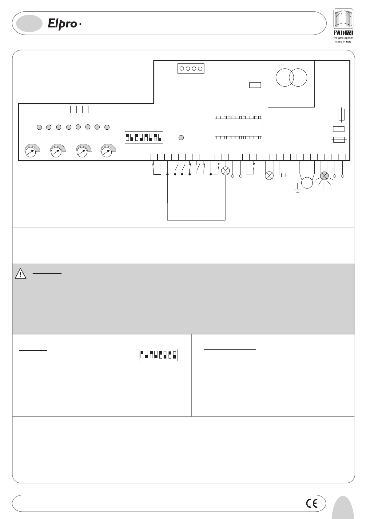
General description: the electronic control panel Elpro 12 Plus, new generation, is designed to operate the sliding gate operator Nyota 115. Power supply is 230V 50Hz
single-phase. Built in full compliance with 2006/95 CE Low Voltage and 2004/108/CEE & 92/31 CEE Electro-Magnetic Compatibility Regulations.
Fitting operations are recommended by a qualified technician in conformity to the existing safety standards.
The manufacturing company declines any responsability for incorrect handling and application; also, it reserves the right to change or update the control panel any time.
Failure to follow installation regulations may result into serious damage to property and persons.
PLEASE NOTE:
- The control panel must be installed in a sheltered, dry place, inside the box provided with it.
- Make sure that the power supply to the electronic programmer is 230V ±10%
- Make sure that the power supply to the Electric Motor is 230V ±10%
- For distances of over 50 metres we recommend using electric cables with bigger sections.
- Fit the mains to the control panel with a 0.03A high performance circuit breaker.
- Use 1.5mm2 section wires for voltage supply, electric motor and flashing lamp. Maximum recommended distance 50m.
Use 1mm2 section wires for limit switches, photocells, push-buttons/key-switch and accessories.
- Bridge terminals 1 and 2 if no photocells are required.
- Bridge terminals 3 and 6 if no key- or push-button switches are required.
N.W: To fit extra accessories such as lights, CCTV etc. use only solid state relays to prevent damages to the microprocessor.
Dip-Switch:
1= ON. Photocells. Stop while opening
2= ON. Radio. No reversing while opening
3= ON. Automatic closing
4= ON. Preflashing activated
5= ON. Radio. Step by step. Stop in between
6= ON. Dead Man Control (Dip 4=OFF and Dip 3=OFF)
7= ON. No lamp on during dwell time
8= OFF
. No function
1456782
DIP-SWI TCH
3
ON
OFF
Led Status Indication:
L1= 230V 50Hz power supply. Alight
L2= Photocells, if obstructed light goes off
L3= Open. Alight whenever an Open pulse is given
L4= Close. Alight whenever a Close pulse is given
L5= Stop. It goes off on pulsing Stop
L6= Radio. It goes on by pressing a transmitter button
L7= Gate Status; it flashes on gate opening
L8= Limit switch Close; off when gate is closed
L9= Limit switch Open; off when gate is open
In case of failure of the panel:
- Make sure that the power supply to the electronic programmer is 230V ±10%
- Make sure that the power supply to the Electric Motor is 230V ±10%
- For distances of over 50 metres we recommend using electric cables with bigger sections.
- Check fuses
- Check photocells if contacts are normally closed
- Check all NC contacts
- Check that no voltage drop has occurred from the control panel to the electric motor
Drwg. No.
4086
5
Page 3

®
GB
LOW VOLTAGE ELECTRICAL CONNECTIONS
Photocells and Safety Edge:
2
1
PHOTOCELLS
AND SAFETY EDGE
12 13
12
24V OUTPUT (500 mA) (MAX. LOAD:
2 PAIRS PHOTOCELLS
1 RADIO RECEIVER)
PLUS
SINGLE-PHASE FOR NYOTA 115 SLIDING GATE OPERATOR
DIP-SWITCH 1:
ON: Photocells stop gate while opening,
reverse it on closing once obstacle is removed
OFF: Photocells do not stop gate while opening,
1
reverse it on closing in case of an obstacle
Button switch:
Radio Contact:
- Open/Close (Standard)
- Travel reversing on
pulsing
- Step by step
Push Button Switch Pulin 3:
24V 3W Indication Light:
Light ON = Open gate
Light OFF = Closed gate
Flashing (fast) 0.5s= Closing gate
Flashing (normally) 1s= Opening gate
Flashing (slowly) 2s= gate is stopped
3
COMMON
3
COMMON
4
OPEN
5
CLOSE
7
RADIO
CONTACT
COMMON
3
6
STOP
28
26
27
Led to indicate status of
Open - Stop - Close
switches
3
11
Limit switch:
DIP-SWITCH 2 and 5 (NEVER set BOTH of them ON
at the same time):
ON: Gate is not reversed while opening
OFF: Any pulse reverses the gate
2
ON: Step by step. Stop in between
OFF: Standard operating mode
5
Safety Contact:
CLOSE
14
8
LIMIT SWITCH
15
10
9
LIMIT SWITCH
OPEN
COMMON
This contact must be
N.C. for the control
panel to be allowed to
work
ELECTRICAL POWER CONNECTIONS
Capacitor and Single-phase Motor (230V):
Flashing lamp:
19
20
ON: Pre-flashing
OFF: No pre-flashing
4
ON: Lamp is not operating during
Dwell time. Automatic mode.
OFF: It flashes during Dwell Time.
230V MAX 25W
7
Automatic Mode.
Courtesy light:
Connect a 24VAC Modular Relay
R63 Trimmer Time from 2s to 255s)
(
to operate a 230V lamp
6
Drwg. No.
4086
DIP-SWITCH 4 and 7:
23 24
29
30
Capacitor
20μF for 0.5HP
40μF for 1.0HP
Trimmer R63
-
COURTESY LIGHT
FROM 2 UP TO 255s
181617
COMMON
M
FROM 2 UP TO 128s
R65
-
MOTOR RUN
TIME
OPEN/CLOSE
+
R64
+
-
DWELL TIME
FROM 2 UP TO 128s
Power supply:
21 22
POWER SUPPLY
230V ±10% 50Hz
SINGLE-PHASE
+
Page 4

GB
OPERATING MODES
12
PLUS
SINGLE-PHASE FOR NYOTA 115 SLIDING GATE OPERATOR
®
Automatic / Semiautomatic:
Automatic Operation: any pulse opens the gate, the gate stays open as long as the Dwell time expires
as set by R64 trimmer, then it closes automatically, no pulsing is required.
Semi-automatic Operation: any pulse opens the gate that stays open. A second pulse to Close is required
for the gate to close.
Pedestrian Opening:
Gate in fully closed position; an Open pulse opens the gate a span equals to the time set
by Pedestrian Trimmer
Hold on switched (Deadman) control:
Open and Close operations are achieved “by holding a switch on” (no relay self-holding
is involved) therefore a phisical attendance is required to keep the gate opening or
closing until either the button or key is released.
Time Clock Installation (Optional):
How it works: Set the clock to the required times. On the pre-set time the gate is automatically
opened and held open. Any further pulsing (even by remote control) is not accepted by
the system until the time pre-set by the clock has expired. On expiring and after the preset dwell time the gate is closed automatically.
R62 trimmer on to zero, Dip-Switch 3=ON.
COMMON
Trimmer R64
-
Dwell Time
from 2 to 128s
3
COMMON
DIP-SWITCH 6
ON= Deadman Control. Dip-switch 4=OFF
and Dip-switch 3=OFF
OFF= Standard Operations
6
4
OPEN
External Time Clock
43
OPEN
NO
+
COMMON
DIP-SWITCH 3
ON= Automatic Closing
OFF= No Automatic. Semi-automatic
3
closing by pulse
Trimmer R62
+
-
Trimmer R62 at minimum
disactivates Pedestrian Opening
from 3 to 30s. It can be activated
by any pulse superior to 2s
DIP-SWITCH No.3=ON Automatic Closing
ON= Automatic Closing
OFF= No Automatic. Semi-automatic
3
closing by pulse
+
-
Pedestrian Trimmer R62
set on to zero
Drwg. No.
4086
7
Page 5

04-2010
I -
Prima dell’installazione da parte di personale tecnico qualificato, si consiglia di prendere visione del
Libretto Normative di Sicurezza che la Meccanica Fadini mette a disposizione.
GB -
Please note that installation must be carried out by qualified technicians following Meccanica Fadini’s
Safety Norms Manual.
F -
’installation doit être effectuée par un technicien qualifié suivant le manuel des Normes de Sécurité
L
de Meccanica Fadini.
D -
Vor der Montage von einem Fachmann, wird es empfohlen die Anleitung zur Sicherheitsnormen, die
Meccanica Fadini zur Verfügung stellt, nachzulesen.
E -
Antes de la instalación por el personal técnico calificado, se recomienda leer detenidamente el Folleto
de la Reglamentación de Seguridad que la empresa Meccanica Fadini pone a su disposición.
Voordat de installatie door gekwalificeerd technisch personeel wordt uitgevoerd, wordt geadviseerd
NL -
om het boekje met veiligheidsvoorschriften dat Meccanica Fadini ter beschikking stelt door te lezen.
®
®
s.n.c.
s.n.c.
Via Mantova, 177/A - C.P. 126 - 37053 Cerea (Verona) Italy - Tel. +39 0442 330422 r.a. - Fax +39 0442 331054
e-mail: info@fadini.net - www.fadini.net
La ditta costruttrice si riserva di apportare modifiche al presente libretto senza preavviso
 Loading...