

Page 1
GB
Elpro 10
VOLTAGE
230 V
400 V
3
4
1 PULSE: PEDESTRIAN OP ENING
PEDESTRIAN OPERATOR
Should more pairs of photocells be
required than the recommended
quantity, fit an auxiliary transformer
THIS PANEL IS TESTED TO OPERATE GATES ONLY
THROUGH FADINI ACCESSORIES. NO WARRANTY IS
ACKNOWLEDGED BY THE MANUFACTURER IN CASE
THAT OTHER ACCESSORIES ARE USED OR NON
E WITHOUT THE
MANUFACTURER’S APPROVAL.
630 mA FUSE
1 Amp.
1 A FUSE
5 A FUSES
“OPEN”
MAINS
“CLOSE”
1
2 3 4 5 6
7 8
PHOTO CELLS
. CONTACT. OPEN
LIMIT SWITCH. COMMON.
24 Vac OUTPUT
Max permitted load :
M
M
NEUTRAL
COMMON
26
TERMINALS FOR THE
24 V POWER
RADIO CONTROL
DWELL TIME
MOTOR RUN TIME
+
+
–
N.C. CONTACT
24 V OUTPUT
D.S.A.
ELPRO 10 F
ON
1
B
ON
OFF
2
3
4
5
6
7
8
9
11
12
10
EARTH
BRAKE
BRAKE FORCE
5 4 3 2 1
3
7
ALL OPERATIONS
27
28
CHANGE-OVER SWITCH
D.S.A.
D.S.A.
SLIDING GATES
THREE-PHASE / SINGLE-PHASE
CONNECTION OF THE
PUSH BUTTONS PULIN 3
DIP-SWITCH
SUPPLY
1° CHANNEL
PLUG-IN CARD SUPPORT
P.C. BOARD
ON VOLTAGE
1 2 3 4 5 6 7 8 9 10
TRANSFORMER
SAFETY EDGE
LED
24 25
26 27
PHOTO CELL
TRANSMITTER
11 12 13 14 15
FLASHING LAMP
FUSE: 24V OUTPUT
TERMINALS 12-13
OPEN & CLOSE
RELAY
CONNECTION
16
17 18 19 20 21 22 23
CONNECTOR
RELAY
RELAY
ADJUSTABLE
SWITCH
LOGIC
HIGH VOLTAGE
COMMON
OPEN, CLOSE
& REVERSE
RADIO CONTACT
N.C. CONTACT
N.O
2 PULSES: FULL OPENING
RADIO CONTACT
N.C. CONTACT. STOP
N.O. CONTACT. CLOSE
LIMIT SWITCH. CLOSE. N.C.
Drwg. No.
3442
SINGLE-PHASE
ELECTRIC
MOTOR
THREE-PHASE
ELECTRIC
MOTOR
N.W.:
CONFORMING APPLICATIONS ARE MAD
LIMIT SWITCH.OPEN. N.C.
24 V INDICATOR – 3 Wmax
2 pairs photocells
1 radio receiver
outside the control box.
CONTACT
N.C. SAFETY
24 Vac POWER OUTPUT
FOR THE ELECTRIC LOCK
ELECTRONIC PROGRAMMER FOR SLIDING
GATES THREE- AND TWO-PHASE
FITTED WITH ELECTRONIC BRAKE AND
D.S.A. (Autotest Safety Device)
SUPPLY VOLTAGE
230 V SINGLE-PH.
21 22 23
SUPPLY VOLTAGE
230-400 V
230 V FLASHING LAMP – 25 Wmax
THREE-PHASE
LIVE
15
14
Page 2
5 2 4
1
BRAKE FORCE
5
4
3
2
1
meccanica
GB
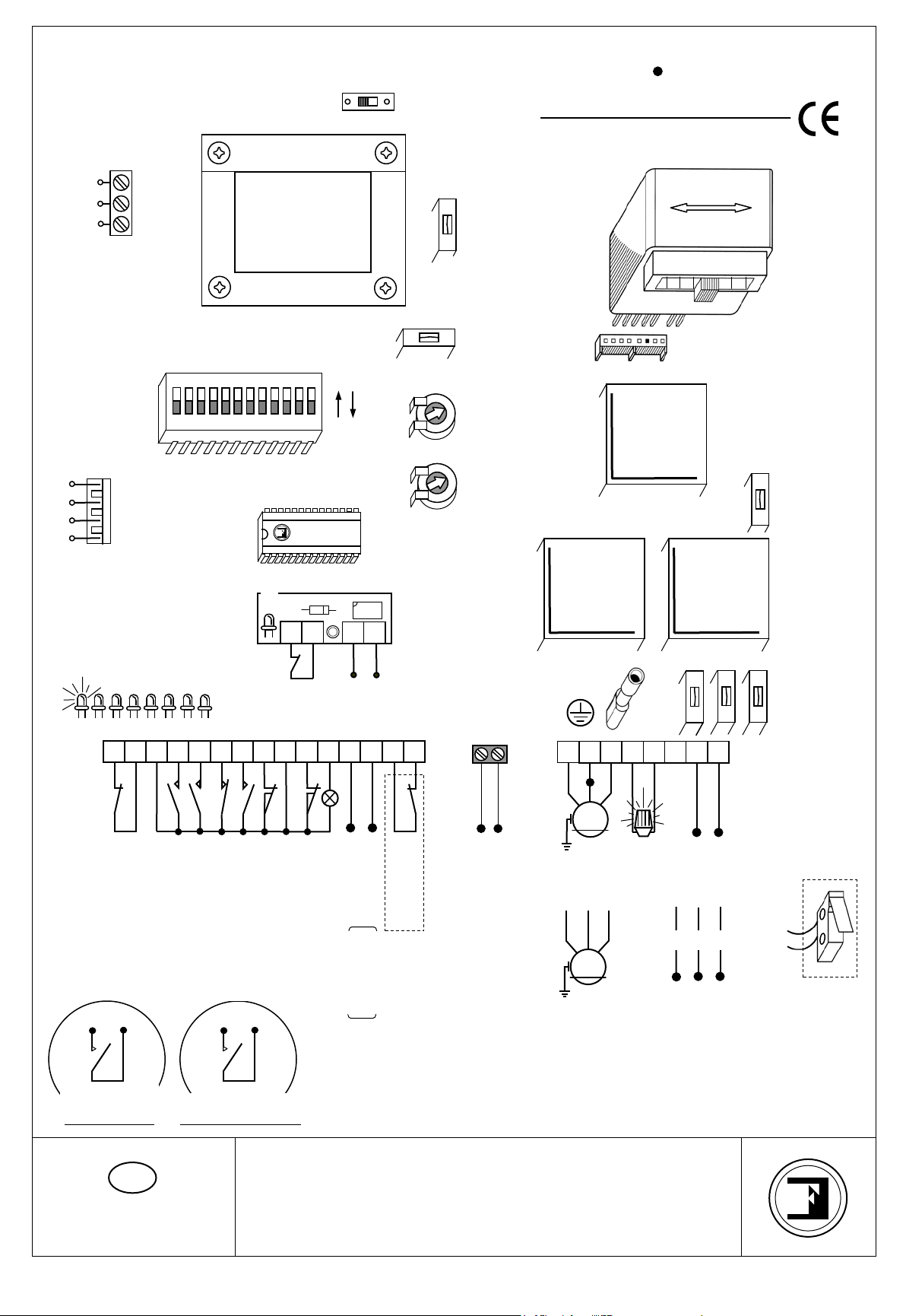
ELECTRONIC CONTROL PANEL ELPRO 10 D.S.A. FOR SINGLE/THREE-PHASE SLIDING GATE SYSTEMS
FUNCTIONS: AUTOMATIC – HOLD ON SWITCHED CONTROL (DEADMAN CONTROL) – PARTIAL PEDESTRIAN
OPENING – STEP BY STEP BY THREE PUSH BUTTONS – SAFETY PHOTO CELL SELFTESTING (AUTOTEST) –
ANTI-CRUSH SAFETY EDGE – ELECTRIC LOCK OUTPUT – ADJUSTABLE ELECTRONIC BRAKE CONTROL
DESCRIPTION OF THE FUNCTIONING WITH SLIDING GATES
D.S.A. PHOTOTEST SAFETY DEVICE:
By connecting the D.S.A. card to the terminals 26 – 27 the photo cell transmitter is 24 V power supplied. In case of
more photo cells, connections are in parallel, the receivers are connected to the 24 V output, terminals 12 – 13.
Always bring contact to terminal 1 –2 in the main board for all the photo cells of the systems. Once satisfied that the
electrical connections are all right, set 9 and 10 of Dip-switch “B” as described in the section setting the safety
devices of the system.
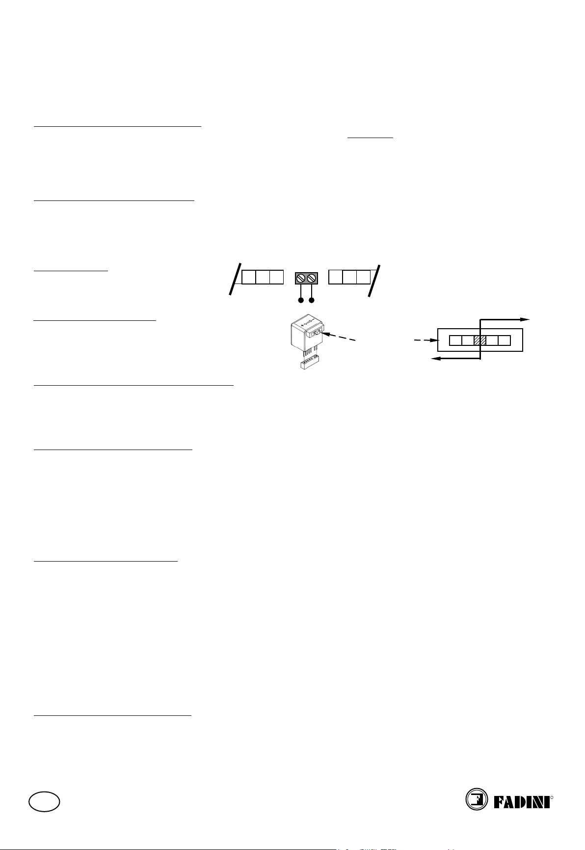
ADJUSTING D.S.A. SAFETY EDGE:
The N.C. connection of the D.S.A. card to terminals 24 – 25 allows control of the safety edge. Should more safety
edges be required, these are to be series connected. Whenever an obstacle touches the safety edge, the system
reverses the gate travel direction for a short spell to allow the removal of the obstacle. Reversing can be set by Dipswitch “B” No. 11 – 12 as described in the respective section.
ELECTRIC LOCK:
Connection is by the provided terminals.
8 9 10
ADJUSTING BRAKE POWER:
The force of the brake can be controlled by a step
switch from step 1 to step 5. (Optional) the switch can
be fitted in the provided connector positioned on the
electronic PC board.
FUNCTION LOGIC OF THE CONTROL PANEL:
The motor run OPEN/CLOSE time must be set to a longer time than that of the actual travel of the gate. The DWELL ie.
wait time before re-closing is to meet the site requirements. On pulsing to open, the lamp goes on first and after three
seconds the motor starts. On dwell time the flashing lamp is still on, after the gate has reached the fully closed position
the lamp continues to stay on for three more seconds. Pre-flashing can be eliminated by Dip-switch “B” No.4.
FAULT DETECTION LED INDICATORS
LED No. 1: It switches on when voltage is supplied.
LED No. 2: “Photo cells” normally on. It switches off when the photo cells are obstructed.
LED No. 3: “Open” normally off. It switches on when the respective switch is activated.
LED No. 4: “Close” normally off. It switches on when the respective switch is activated.
LED No. 5: “Stop” normally on. It switches off when the respective switch is activated.
LED No. 6: “Radio” normally off. It switches on by pulsing either the remote control, keyswitch or push buttons.
LED No. 7: “Limit switch. Close” normally on. It switches off when the gate is fully closed.
LED No. 8: “Limit switch. Open” normally on. It switches off when the gate is fully open.
NOTES TO WIRING OPERATIONS
1) It is advisable not to expose the control box directly to weather conditions. If mounted outside, a suitable
enclosure is recommended to protect it from sunshine and rain.
2) Earth the equipment.
3) Bridge terminals 1 – 2 if you do not require any photo cells.
4) Should two sets of photo cells be required, these are to be series connected to terminals 1 – 2, contact normally
closed. If mounted to the same side of the gate, cross install them ie. projector of one pair next to the receiver of
the second pair.
5) Bridge terminals 3 – 6 if you do not require any keyswitch or push buttons.
6) Fit the mains to the control box with a 0.03 A high sensitivity magnetic-thermal circuit breaker.
7) For single-phase motors the cable square section must not be inferior to 1,5 mm
8) The 24 V~ output ie. terminals 9 – 10 can take 2 pairs of photo cells and 1 radio receiver maximum. Should extra
photo cells or receivers be required, fit an auxiliary transformer outside the control box.
IN CASE OF FAILURE OF THE PANEL
1) Check voltage: it must be 230 V single-phase / 400 V three-phase.
2) Check high voltage fuses.
3) Check low voltage fuses.
4) Check photo cells: contact must be normally closed.
5) Check voltage from the control box to the electric motor in case power has dropped.
Drwg. No. 3442 Page 2
11
12 13
ELECTRIC LOCK POWER SUPPLY OUTPUT
STEP SWITCH
2
.
LESS POWER
MORE POWER
Page 3

SETTING A PROGRAM WITH ELPRO 10 D.S.A. DIP-SWITCH
OFF
SETTING FOR PARTIAL PEDESTRIAN OPENING.
distance set
8 as explained below; a second pulse opens the
gate full travel.
ON
B
1
2
3
4
5
6
7
8
9
11
12
10
7 8
ON
8
ON
7
8
7
8
Full opening
1,5 meter opening
2 meter opening
PHOTO CELL TRANSMITTER - TERMINALS No. 26 – 27
ON
B
ON
1 2 3
4
5
6
7
8
9
11
12
10
No. 9 ON = PHOTO CELL CONTROL TEST BEFORE GATE OPERATION
ON
OFF
B
1 2 3
4
5
6
7
8
9
11
12
10
11 12
reverse 5 cm
11 12
ON
11 12
ON
reverse 15 cm
11 12
ON
reverse 30 cm
GENERAL DIAGRAM
B
ON
OFF
1 2 3
4
5
6
7
8
9
11
12
10
No. 1 ON = PHOTO CELLS. STOP DURING “OPEN” CYCLE
ON
meccanica
“HOLD ON SWITCHED CONTROL”: any open or close operations require that the respective switch
GB
N.W.: The electronic control panel Elpro 10 D.S.A. has been designed to suit any FADINI sliding gate operator and
accessories. The manufacturer is not responsible for incorrect use of Elpro 10 D.S.A. with other applications or with
accessories that are not FADINI compatible, for misuse of the electronic P.C. board and damages derived from it.
All the electrical connections are to be made as per the instructions and diagrams here
described. Supply the terminals 21 – 22 –23 with 230/400 V, 50 Hz voltage. The “red led” No.1
switches on and stays on as long as the board is properly supplied. Set DIP-SWITCHES “B” to meet
the site requirements.
Drwg. No. 3442 Page 3
DIP-SWITCH
. Dip-switches No. 1 – 2 – 3 – 4 – 5 – 6
No. 1 OFF = PHOTO CELLS. NO STOP DURING “OPEN” CYCLE. REVERSE ON CLOSING
No. 2 ON = REMOTE CONTROL. NO REVERSE TRAVEL ON OPENING
No. 2 OFF = REMOTE CONTROL. REVERSE TRAVEL
No. 3 ON = AUTOMATIC RE-CLOSING
No. 3 OFF = NO AUTOMATIC RE-CLOSING
No. 4 ON = PRE-FLASHING
No. 4 OFF = NO PRE-FLASHING
No. 5 ON = REMOTE CONTROL. STEP BY STEP. STOP IN BETWEEN
No. 5 OFF = REMOTE CONTROL. GATE CAN BE REVERSED WHILE TRAVELLING
No. 6 ON = “DEADMAN CONTROL” (HOLD-ON SWITCHED). SET No.3 TO OFF
No. 6 OFF = OUT OF SERVICE. NORMAL OPERATING MODE
button or key is hold on pressed or turned until the end of the
operation.
DIP-SWITCH
ON
A first “OPEN” pulse to terminal No.4 opens the gate to the
through the switches 7 –
7
1 meter opening
DIP-SWITCH
SETTING THE SAFETY DEVICES OF THE SYSTEM. Dip-switches No. 9 – 10
ON
DIP-SWITCH
OFF
(ie. phototest with the photo cell transmitter connected to the provided output)
No. 9 OFF = PHOTOTEST OUT OF SERVICE
No.10 ON = PHOTO CELL ALIGNMENT CONTROL TEST – NO OBSTRUCTION BEFORE GATE OPERATION
No.10 OFF = TEST OUT OF SERVICE
D.S.A.” CARD
“
SETTING SAFETY ED GE C O NT RO L . Dip-switches No. 11 – 12
D.S.A.” CARD
“
SAFETY EDGE - TERMINALS No. 24 – 25
ON
reverse 10 cm
ON
Dip-switches No. 7 – 8
ON
Page 4

GB
Elpro 10
TECHNICAL SPECIFICATIONS
CCTV etc…,
meccanica
s.n.c.
REMOTE CONTROL
BRAKE
FAULT DETECTING
LEDs
TERMINAL
ELECTRIC LOCK
TRANSFORMER
BRAKE FORCE
TERMINAL
TERMINAL TO
VOLTAGE
CHANGEOVER
D.S.A.
HIGH VOLTAGE
EARTH
N.C. SAFETY
SWITCH 400V – 230V
D.S.A.
CONNECTOR
Vin=230-400 V
Vout=24 V 1A
CONNECT
THE PUSH BUTTONS
PULIN 3
DIP-SWITCH B
CARD CONNECTOR
AUTOTEST
SAFETY
DEVICE
CARD
BOARD
ADJUSTABLE SWITCH
FUSES
SWITCH
BOARD
CONNECTION
TERMINALS
ELECTRIC CABLE
INLET
Supply voltage 230/400 V – 50 Hz
Voltage output 230 V – 25 W
Low voltage output 24 V – 10 W
E.M. max. power output 1.100 W
Mains fuses 5 A
Secondary fuses 1 A – 630 mA
Logic Open – Stop – Close
Box dimensions 285 x 205 x 110 mm
Protection Standards IP 473
Elesta relay approval marks VDE-CSA-DEMCO-SEV
10 A – 230 V
4 A – 400V
TRANSFORMER
Power rate 80 VA
Magnetic core 1,5 W / 0,50 Thick.
Voltage 0 – 230 V
Outputs 0 – 12 – 18 – 24 V
Working frequency 50 / 60 Hz
Insulation 4 Kv x 1’
N.W.: For special applications ie. to switch on lights –
SOLID STATE RELAYS are recommended to prevent the microprocessor from being affected.
Drwg. No.
3442
R
AUTOMATIC GATE MANUFACTURES
Via Mantova 177/A - C.P. 126 - 37053 Cerea (VR) Italy
Tel. +39 0442330422 r.a. - Fax +39 0442331054
e-mail: info@fadini.net - www.fadini.net
 Loading...