

Page 1

CORAL 1050
CORAL 1080
Retractable oil-hydraulic
traffic control post
Diameter ø100mm
Stroke 500 mm
Stroke 800 mm
Instruction manual
GB
Page 2
INSTRUCTIONS TO BE FOLLOWED BEFORE INSTALLING THE OPERATOR
FOR OPTIMAL APPLICATION AND USE OF THE OPERATOR PLEASE READ THE INSTRUCTIONS AND CONSULT EXPLANATORY DIAGRAMS.
IMPORTANT: ALL INSTALLATION OPERATIONS MUST BE PERFORMED BY A QUALIFIED TECHNICIAN, IN OBSERVANCE OF THE
EN 12453 - EN 12445 SAFETY REGULATIONS AND MACHINERY DIRECTIVE 98/37/EC. CAREFUL RISK ANALYSIS IS REQUIRED UNDER
APPLICABLE REGULATIONS
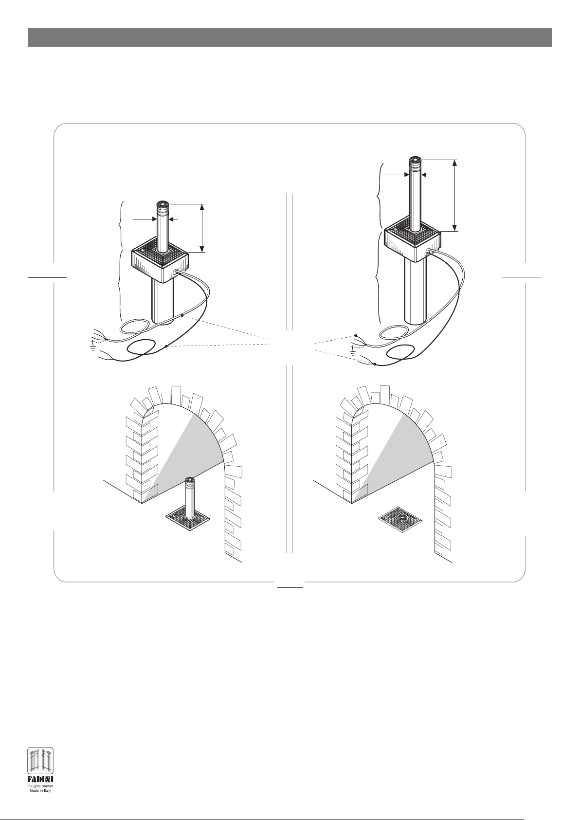
A - Retractable post that moves vertically out of the road paving
Coral 1050
B - Container unit inside the housing to be sunk in a dedicated
trench in the ground
FA
D
IN
I
l
’
a
p
r
i
c
a
n
c
e
l
l
o
Ø100
A
stroke
500mm
B
Length of
electrical cables
10 metres
FA
D
IN
I
l
’
a
p
r
i
c
a
n
c
e
l
l
Ø100
A
B
o
stroke
800mm
Coral 1080
F
A
D
I
N
I
l
’a
p
r
ic
a
n
c
e
ll
o
Coral 1050 and Coral 1080
with raised post
access prohibited
Coral 1050 and Coral 1080
with lowered post
access free
PIC. 1
OVERVIEW
This product belongs to our range of retractable traffic control posts. It is quick and easy to install, as it does not need to be adjusted or
calibrated and has been designed to regulate and prohibit vehicular access.
Both the CORAL 1050 and CORAL 1080 oil-hydraulic operators have anti-corrosion treated steel posts with a diameter of Ø100mm and
ranges of 500mm (Coral 1050) and 800mm (Coral 1080).
The product’s hallmark is its ease of installation: once the housing has been secured, the operator can be introduced ready for operation,
as soon as the wiring has been completed.
As soon as the retractable post receives a command (from a key switch or radio transmitter), it rises from its interred position. The post
is clearly visible at nighttime thanks to a reflective strip and the possibility of connecting a flashing light or traffic light. Using the electronic
microprocessor programmer, the operator can also be customised with presence indicator accessories (magnetic coils, presence
indicator photocells).
PRELIMINARY OPERATIONS
Before starting installation operations, it is important to follow the indications given below:
- Before digging the trench to house the housing, check that there are no pipes or other utilities that could interfere with
the preparatory operations.
- Check the firmness and consistency of the ground.
®
- Remove any obstacles hindering the post’s movement.
2
Page 3
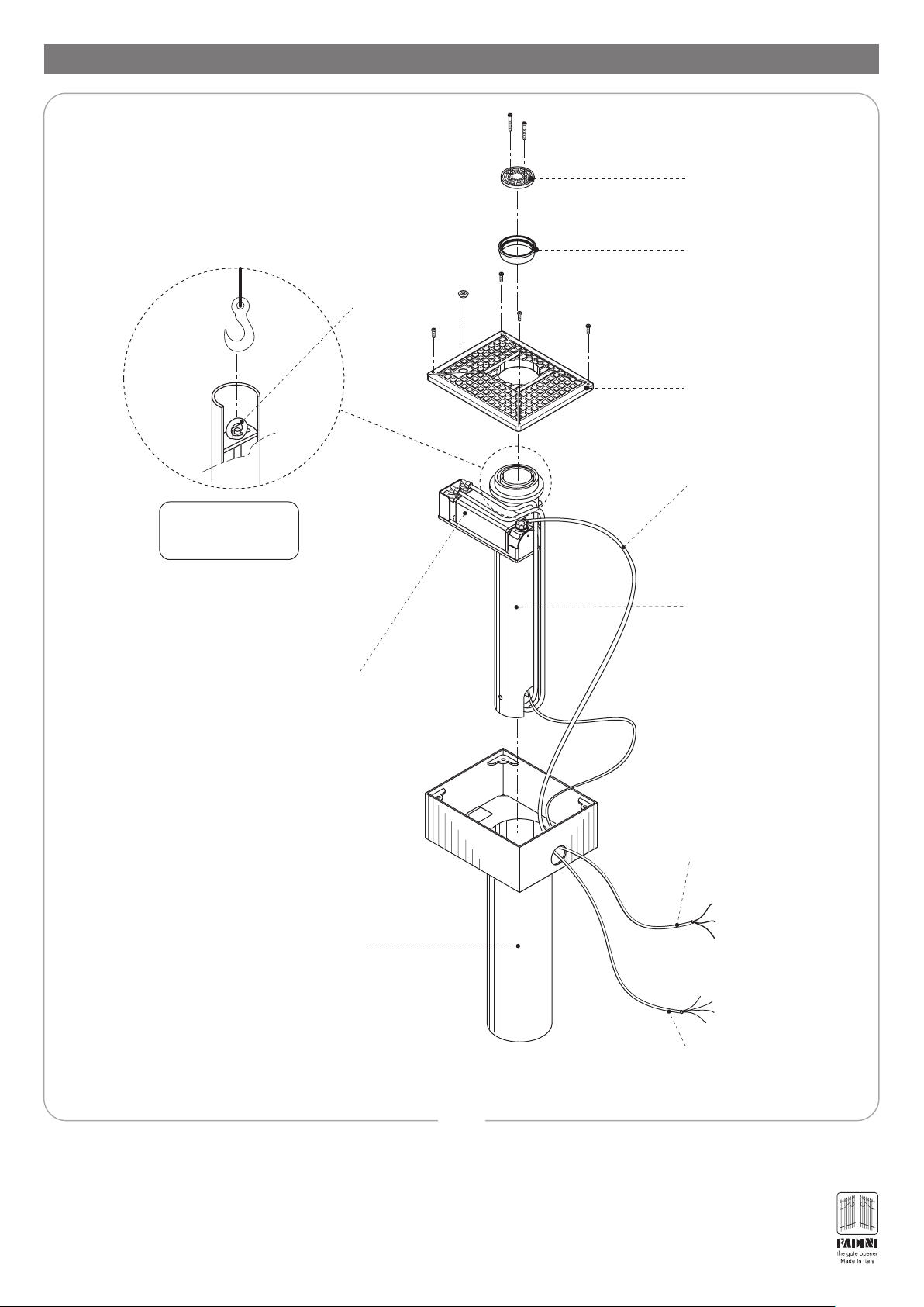
PRELIMINARY OPENING OF ALL FUNCTIONAL COMPONENTS
Eyebolt
Post cover
Rubber buffer
Cover plate
Electric motor cable,
10 metres
Detail of retractable post
with hoisting connection
Housing to be cemented
Cylindrical container for oilhydraulic piston
Hydraulic
main unit
Cable for opening limit
switch (post lowered),
10 metres
into the ground
Electric motor cable,
10 metres
PIC. 2
Start by removing the cover plate to reveal the operator and separate the individual components, with the aid of a hoist. Pic.2: this makes it
easy to extract the internal piston and hydraulic main unit container unit.
IMPORTANT: take care not to tear or cut wires.
3
®
Page 4
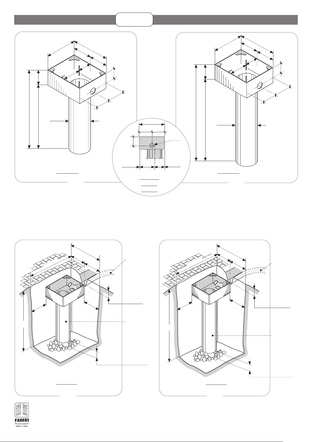
ARRANGING THE HOUSING
CORAL 1050
CORAL 1080
845
675 170
330
200
FRONT SIDE
Ø195
Coral 1050 Housing
PIC. 3 PIC. 4
200
130
400
200
165
120
165
Side
Front
120
Side view
330
165
200
top part
housing
165
130
ø 60
Side
Back
1140
330
170
970
Ø195
Coral 1080 Housing
200
FRONT SIDE
200
400
200
130
120
165
165
The Housing is the component inside which the operator is installed. It is therefore essential, when securing it in the ground to check
that the top edge is level with the ground.
IMPORTANT: the top recess of the Housing (inside which the hydraulic main unit is placed), is not central to the tube below inside which
the oil-hydraulic piston unit is placed: the latter is 13cm from the “Back side” of the Housing (Pic.3 and Pic.4).
Piping
Ø50 mm
for passage
of electric wires
12 cm
Depth
Piping centre
Housing
15 cm
Loose pebble
drainage layer
1.30 m
800 mm
BACK SIDE
FRONT SIDE
200 mm
Buried Coral 1080 Housing
395 mm
790 mm
230 mm
395 mm
Piping
Ø50 mm
for passage
of electric wires
12 cm
Depth
Piping centre
Housing
15 cm
Loose pebble
drainage layer
1.0 m
395 mm
800 mm
BACK SIDE
FRONT SIDE
200 mm
Buried Coral 1050 Housing
790 mm
395 mm
230 mm
PIC. 5 PIC. 6
- Dig a trench in the ground in the point at which the Coral 1050 or Coral 1080 operator is to be installed, according to the
measurements shown in Pic.5 and Pic.6, and connect a Ø50 mm pipe leading to the Elpro S40 electronic programmer (10 metres
®
of cable are provided).
Place a 15 cm deep layer of loose gravel and pebbles on the bottom.
4
Page 5

Spirit
level
Concrete
cast
- Once the housing has been positioned and installation
completed, it is important for the top edge to be level
with the ground (Pic. 7 and Pic. 8)
IMPORTANT: The top edge of the
housing must be level with the ground
!
when installation has been completed
Concrete
cast
FRONT SIDE
cover with about 30 cm
of concrete
30 cm
Cover rest of housing with earth
Housing CORAL 1050
Housing CORAL 1080
PIC. 7
PLACING THE TRAFFIC CONTROL POST INSIDE THE HOUSING
Hoisting
hook
Piston
container unit
CORAL 1050
CORAL 1080
CORAL 1050
CORAL 1080
Electric motor and limit switch
cables,
10 metres
3
4
1
2
Elpro S40 electronic
programmer wall-mounted
in a protected place
51
50
Housing
Buried piping
Ø50 mm
PIC. 8
Before performing this operation, wait for the housing to be secured firmly in place. Do not commence until the concrete has set and
the electric wire pipe has been secured and covered with soil.
- Use a hoisting hook to lift the piston unit with the post and main unit (using the eyebolt) and place on top of the housing.
- The subsequent phase of this operation consists in threading the motor and limit switch electric wires through the piping and simultaneously
starting to delicately place the operator inside the housing.
IMPORTANT: Pass the motor and limit switch electric wires through the piping without tearing or cutting the cables. Pic.8.
5
®
Page 6

ELECTRIC CONNECTIONS WITH THE ELECTRONIC PROGRAMMER
Traffic lights card 230V
power supply
RED
YELLOW
GREEN
60 61
63 64 65 66
External three-light
traffic lights
51 52 53
S40
230V input ±10% 50 Hz
Siti 63 Plug-in
radio receiver
Programmer
Important: Place a jumper
between the Common and
the Closing limit switch
(terminals 12 and 13)
S40
20µF
Siti
20 µF
Capacitor
1 2 3 4 5 6 7 8 9
26 27 28 29 30
11 12 13 14 15
31 32 33 34 35 36
22 23 24 25
16 17 18 19 20 21
70/1
M1
OPENING LIMIT SWITCH M1
(Post lowered)
CLOSING LIMIT SWITCH
(Post raised)
11
Brown
14 15!16 17 18
13
12
Black
LIMIT SWITCH
COMMON
Common
MOTOR COMMON
MOTOR PHASE
MOTOR PHASE
Connect all yellow-green
wires to the grounding in this
!
terminal.
SOLENOID VALVE
POWER SUPPLY
(OPTIONAL)
22 23
Apply a 0.03A
high-sensitivity
differential
thermomagnetic
circuit breaker
Earthing
Dark blue wire
NO contact
not used
®
6
Earthing
Limit switch cable
cable
Electric motor
Solenoid valve cable
(Optional on request)
CORAL 1050
CORAL 1080
Buried
PIC. 9
Two electric cables are provided with Coral 1050 and Coral 1080 traffic control posts: one to connect the 230V 50Hz
electric motor to terminals 16, 17 and 18 and another one to connect to the terminal of the opening limit switch 11
and the common 13 (Pic.9).
Place a jumper between terminals 12 and 13 of the closing limit switch
Page 7

WIRING DIAGRAM SHOWING CONNECTIONS WITH THE ELECTRONIC PROGRAMMER
F
A
D
IN
I
S40
+-
55 56
-
T2
DWELL TIME
1s - 180s
9101112
24V DC OUTPUT
+
ON
OFF
L12 L13 L14 L15
26 27 28 29 30
(Post lowered)
M3 OPENING LIMIT SWITCH
(Post raised)
CONNECTOR FOR 3 LIGHT
TRAFFIC LIGHTS,
MAX 100W PER BULB
-
+
Siti
T1
OPERATING TIME
1s - 22s
14567823
SUPPORT FOR
PLUG-IN RADIO
CARD
DIP-SWITCH
Elpro S40
L3
L2
L1
Input P
17410285396
57 58
Traffic control post motor M1
Pedestrian passage
magnetic coil
Contact terminal
Photoelectric cell or
Common
Open
L4
Close
Stop
L5
L6
Indicator light 24V 3W max
Radio
- 1 Radio receiver
- 2 pairs of photoelectric cells
L7
Output 24V 250mA for max. load:
FIRST OPERATION MANOEUVRES
Secondary Fuse
Transformer
F4= 2A
M3O M3C M4O M4C
Capacitor
C
O
M
M
O
N
(Post lowered)
M4 OPENING LIMIT SWITCH
(Post raised)
M4 CLOSING LIMIT SWITCH
M3 CLOSING LIMIT SWITCH
3
L8
L9
L10 L11
11 12 13
14 15
C
O
M
M
(Post lowered)
M1 opening limit switch
O
N
(Post raised)
M1 closing limit switch
(Post lowered)
M2 opening limit switch
CORAL 1050
CORAL 1080
20VA 50/60Hz
TRANSFORMER
Capacitor
20µF M4
20µF M3
AA
BB
34
36
35
333132
C
C
O
O
M
M
M
M
O
O
N
N
M4
M3
M3 MOTOR
Traffic control post no. 3
Traffic control
post no. 4
4
Capacitor
20µF M1
A
C
O
M
(Post raised)
M2 closing limit switch
M
O
N
control post no. 1
12
Fuse
Motor M4
F6= 5A
Fuse
Motor M3
F7= 5A
M4 MOTOR
Capacitor
20µF M2
A
B
1816 17
21
19 20
C
O
M
M
O
N
M1
M2
M2 MOTOR Traffic
control post no. 2
M1 MOTOR Traffic
Primary Fuse
Transformer
F3= 630mA
51 52 53
COMMON
Fuse for Solenoid Valve,
Buzzer, Flashing Light
and LED F5=1A
Fuse Motor M2
Fuse Motor M1
Anti-disturbance filter
B
2322 24 25
power supply
230V 50Hz
F2= 5A
F1= 5A
P
H
A
N
F
S
E
Panel power supply
Solenoid valve
230V ±10% 50Hz
Single-phase
FLASHING LIGHT
230V 100W max
l’a
p
r
ic
a
n
c
e
l
lo
N
E
U
T
R
A
L
Ref. Drwg. No.
4555
PIC. 10
ATTENTION: it is important to establish the exact position
of the traffic control post, open or closed, according to
!
whether it allows or prohibits vehicular access (Pic. 11)
Traffic control post
FADINI
l’apricanc
ello
Having terminated installation of the traffic control post and all the
safety and control accessories and the respective connections with
the Elpro S40 programmer, and having completed thorough risk analysis,
the first operation manoeuvres can be performed. If you have a radio
Post in raised position:
Access prohibited
transmitter, encode the radio receiver according to the relative
instructions before giving the command to raise the retractable post,
or give the manoeuvre command using a key switch. Pic.11.
Phase
Phase
During first use, it is important to check whether the wiring of the
Common
Switch over phases
electric motor phases corresponds to the "open" and "closed" positions
of the traffic control post, with the post raised limit switch (access
prohibited), if this is not the case, switch over the two “phase” wires,
16 17 18 16 17 18
leaving the common fixed (Pic. 12).
CORAL 1050
GROUND-LEVEL CLOSURE OF COVER PLATE
- Use the four screws to close the Cover Plate (Pic.13)
- Lift the retractable post for facilitate closure of the post cover with
the buffer, give the command (by encoding a transmitter with the
radio receiver or a key switch Pic.12) to lift the retractable post (Pic.13).
CORAL 1080
Cover
Buffer
PIC. 11
PIC. 12
GREASE
Post lowered:
Access open
Phase
Phase
Common
IMPORTANT:
WE RECOMMEND GREASING
ALL CLAMPING SCREWS
Stop
Cover plate
Retractable
post
F
A
D
IN
I
l’apricancello
®
PIC. 13
7
Page 8

INSTALLATION WIRING
CORAL 1050
CORAL 1080
1
10
11
8
4x1,5mm
2
9
2
3
4
4x1mm
2
7
FADINI
l
’a
p
r
ic
a
n
c
e
llo
2x1mm2RGB cable
4x1mm
2x1mm
2
4x1mm
230V ±10%
2
2
50 Hz
Earthing
6
2
2x1mm
4x1m
- M
2
m
otor
2x1m
itch
it sw
2
- Lim
m
4x1mm
2
5
6
Components
1 - MIRI 4 flashing light with built-in aerial
2 - Wall-mounted Astro 43 radio receiver
3 - Elpro S40 Electronic programmer
4 - Differential circuit breaker switch
(sensitivity 30mA, protection 6-10A)
5 - Junction box, electric wires
6 - Polo 44 photoelectric cell projector
7 - Polo 44 photoelectric cell receiver
8- Prit 19 key switch
9- Two-light 230V traffic light
10 - Coral 1050 or Coral 1080 retractable traffic control post
11 - Astro 43/2 Piccolo transmitter
IMPORTANT:
The whole electric system must be earthed (Pic. 15).
7
PIC. 14
Before making electric connections, carefully read the wiring diagrams attached: Elpro S40 electronic programmer instruction booklet
- Drwg. 4555.
- Power supply, electric motor and flashing light wiring must be made using cables with 1.5 mm2 sections, for a maximum distance of
50 m. For distances of over 50 metres, we recommend using electric wires with sections of 2 mm
- For the Photoelectric cells, button switches and accessories, electric wires with 1 mm
2
sections may be used.
2
.
- The whole electrics system must be earthed.
ARRANGING THE SAFETY AND SIGNALLING ACCESSORIES
CORAL 1050
CORAL 1080
All safety and control accessories must be installed at certain
distances from the operator in order to obtain effective
installation. Connect to earth.
FADINI
l’a
p
ric
a
n
c
e
.
llo
0 m
ARRANGEMENT OF THE PHOTOELECTRIC CELLS
The photoelectric cells must be installed at a minimum
working distance as indicated in Pic. 15.
Prit 19
min 1
ARRANGING VISUAL 344
The 2 or 3-module Visual 344 cabinet is a metal accessory
used to house the Elpro S40 in exposed positions, in those
installation situations in which the programmer cannot be
wall- or recess-mounted. It has also been designed for the
S40
installation of possible control accessories such as intercom
systems or key switches, in the immediate vicinity of the
Coral 1050 or Coral 1080 (pic. 15).
PIC. 15
®
8
Page 9

WIRING 4 TRAFFIC CONTROL POSTS TO THE ELECTRONIC PROGRAMMER
RED
Three-light
traffic lights
Siti 63 Plug-in
radio receiver
YELLOW
GREEN
1
°
R
63 64 65 66
Siti
2
°
R
60 61
26 27 28 29 30 31 32 33 34 35 36
20 µF
3
20 µF
4
S40
230V ±10%
50Hz
High sensitivity
differential circuit-
breaker, type 0.03 A
Earthing
Capacitors sold
loose
separately
Prit 19 key
switch with
STOP
1
20 µF
1 2 3 4 5 6 7 8 9
1 2 3 4 5 6 7 8 9 10
1
11 12 13 14 15
FA
D
IN
I
l’apric
ancel
lo
16 17 18 19 20 21
FA
DI
N
I
l’ap
rica
ncello
2
22 23 24 25
11 12 13 14 15
F1
11 12 13
F2
13 14 15
FA
D
IN
I
l’apr
ic
an
ce
llo
16 17 18 19 20 21
M1
16 17 18
M2
19 20 21
FA
D
IN
I
l’a
pric
an
ce
llo
20 µF
26 27 28 29 30
F3
26 27 28
F4
28 29 30
2
31 32 33 34 35 36
M3
31 32 33
M4
34 35 36
Pull-out
terminals
Polo 44
photoelectric cells
Projector
CORAL 1050
CORAL 1080
3
4
1 - 2 - 3 - 4 - Retractable post
F1 - F2 - Retractable post limit switch 1 and 2
F3 - F4 - Retractable post limit switch 3 and 4
Connecting 4 traffic control posts
to the electronic programmer
S40
Polo 44
photoelectric cells
Projector
PIC. 16
®
9
Page 10

MANUAL RELEASE OPERATIONS
CORAL 1050
CORAL 1080
1) - Unscrew protection cap
12
1
11
2
10
9
3
8
4
567
3) - Release the hydraulic circuit by
turning the release key one turn
anti-clockwise
Release
key
2) - Insert the release key
in the release key
recess
F
ADINI
l’apr
ic
an
cello
12
1
11
2
10
9
3
8
4
567
FADINI
l
’
a
p
ri
c
a
n
c
e
l
lo
5) - Block the hydraulic circuit by
4) - Press to lower the post
manually
turning the release key
clockwise
PIC. 17
In the case of a blackout, the post can be lowered manually following the instructions show in Pic.17. Unscrew the Protection cap (1),
insert the release key into the recess (2) and turn once anti-clockwise to release the hydraulic circuit (3). Press down manually to lower
the column (4) and then block the hydraulic circuit, by turning the release key clockwise (5).
= To raise the post, first “Block” by turning the key clockwise, then give command =
PACKAGING DETAILS
Oil-hydraulic traffic control post CORAL 1050
0.50 m
0.45 m
CORAL 1050
CORAL 1080
0.85 m
0.40 m
R
Oil-hydraulic traffic control post
CORAL 1080
R
0.40 m
0.50 m
0.45 m
1.20 m
Individually packed
on wooden pallet
Total weight of Coral 1050: 91 Kg
PIC. 18 PIC. 19
®
Important: discarded material should be disposed of using the dedicated containers by specialised firms.
10
Individually packed
on wooden pallet
Total weight of Coral 1080: 109 Kg
Page 11

MANUFACTURER'S DECLARATION OF CONFORMITY
CORAL 1050
CORAL 1080
1
s.n.c.
®
R
MANUFACTURER'S
CORAL 1050
Via Mantova 177/A - 37053 Cerea (VR) Italy
Tel. +39 0442 330422 - Fax +39 0442 331054
e-mail: info@fadini.net - www.fadini.net
HEREBY DECLARES UNDER ITS OWN RESPONSIBILITY THAT:
DECLARATION OF CONFORMITY
Manufacturer:
Address:
Model:
retractable traffic control post
2
3
EN 12445 & EN 12453
and that:
IS CONFORMING TO MACHINERY DIRECTIVE .........98/37/CE
- Low Voltage directive 2006/95 CE
Coral 1050 is sold for installation as an automated system, with original accessories and components indicated by the
Manufacturer.
Pursuant to legal provisions, the operator is a ‘machine’ and consequently, the Installer must comply with all applicable
safety regulations. The Installer is obliged to issue his/her own Declaration of Conformity.
The Manufacturer declines all responsibility for improper use of the product
- Electromagnetic Compatibility Directive 2004/108/CEE & 92/31 CEE
The product is conforming to the following specific regulations:
- Risk analysis and subsequent operations to eliminate them:
®
EN 13241-1
Supervisor
Supervising Manager
Meccanica Fadini s.n.c.
PRODUCT STANDARD .........................
09-06-08
In order to certify the product, the Manufacturer declares under its own responsibility that it complies with
Date:
GB
1
s.n.c.
®
R
MANUFACTURER'S
CORAL 1080
Via Mantova 177/A - 37053 Cerea (VR) Italy
Tel. +39 0442 330422 - Fax +39 0442 331054
e-mail: info@fadini.net - www.fadini.net
HEREBY DECLARES UNDER ITS OWN RESPONSIBILITY THAT:
DECLARATION OF CONFORMITY
Manufacturer:
Address:
Model:
retractable traffic control post
2
3
EN 12445 & EN 12453
and that:
IS CONFORMING TO MACHINERY DIRECTIVE .........98/37/CE
Coral 1080 is sold for installation as an automated system, with original accessories and components indicated by the
Manufacturer.
Pursuant to legal provisions, the operator is a ‘machine’ and consequently, the Installer must comply with all applicable
safety regulations. The Installer is obliged to issue his/her own Declaration of Conformity.
The Manufacturer declines all responsibility for improper use of the product
The product is conforming to the following specific regulations:
- Risk analysis and subsequent operations to eliminate them:
- Low Voltage directive 2006/95 CE
- Electromagnetic Compatibility Directive 2004/108/CEE & 92/31 CEE
®
EN 13241-1
Supervisor
Supervising Manager
Meccanica Fadini s.n.c.
PRODUCT STANDARD .........................
09-06-08
In order to certify the product, the Manufacturer declares under its own responsibility that it complies with
Date:
GB
11
®
Page 12

TECHNICAL DATA AND DIMENSIONS
HYDRAULIC MAIN UNIT
Hydraulic pump ......................................................................................................................................P10
Hydraulic pump flow rate ..........................................................................................................4.45 l /min
Mean operating pressure .................................................................................................2 MPa (20 bar)
Maximum pump pressure .................................................................................................4 MPa (40 bar)
Operating temperature......................................................................................................... –20°C + 80°C
Hydraulic oil type .........................................................................................................................Oil Fadini
Main unit static weight ......................................................................................................................10 Kg
Main unit protection class .................................................................................................................IP 54
ELECTRIC MOTOR
Output ..............................................................................................................................0.25 KW (0.33 HP)
Supply voltage .....................................................................................................................................230 V
Absorbed current ................................................................................................................................1.8 A
Frequency ............................................................................................................................................50 Hz
Consumption power ..........................................................................................................................330 W
Capacitor ..............................................................................................................................................20 µF
Motor rotation speed ..................................................................................................................2˙800 rpm
Service mode ...........................................................................................................................................S 3
CORAL 1050
OIL-HYDRAULIC PISTON
Rod exit time..............................................................................................................................4s
Net rod stroke..................................................................................................................500 mm
Rod diameter......................................................................................................................16 mm
Plunger diameter...............................................................................................................30 mm
Thrust force.......................................................................................................................15 daN
Complete protection class ...............................................................................................IP 557
PERFORMANCE CORAL 1050 (STROKE 500mm)
Service cycle......................................4 secs Opening - 30s Dwell - 4s Closing - 30s Dwell
Complete cycle time..............................................................................................................68s
Complete Opening - Dwell - Closing - Dwell cycles:..........................................53 per hour
Annual cycles (considering 8-hour working day): ....................................................154˙000
Packaging Pic.18
(See Pic. 20)
CORAL 1050
CORAL 1080
PIC. 20
10 metres of cable
Electric motor and
limit switch
Ø100
400
Ø195
CORAL 1050 - weight 86 Kg
Ø100
330
170
800
stroke
500
stroke
1350
850
housing
11-2008
CORAL 1080
OIL-HYDRAULIC PISTON
Rod exit time..............................................................................................................................6s
Net rod stroke..................................................................................................................800 mm
Rod diameter......................................................................................................................16 mm
Plunger diameter...............................................................................................................30 mm
Thrust force.......................................................................................................................15 daN
Complete protection class ...............................................................................................IP 557
PERFORMANCE CORAL 1080 (STROKE 800mm)
Service cycle......................................6 secs Opening - 30s Dwell - 6s Closing - 30s Dwell
Complete cycle time..............................................................................................................72s
Complete Opening - Dwell - Closing - Dwell cycles:..........................................50 per hour
Annual cycles (considering 8-hour working day): ....................................................146˙000
Packaging Pic.19
(See PIC. 21)
PIC. 21
10 metres of cable
Electric motor and
limit switch
400
Ø195
CORAL 1080 - weight 104 Kg
330
WARNINGS
- Before performing installation, conduct Risk Analysis and operate using devices compliant with EN 12445 and EN 12453 safety regulations.
- Packaging materials such as cardboard, nylon, polystyrene, etc. should be disposed of using specialised waste collection firms.
- If the operator is removed, do not cut the electric wires, rather remove them from the terminal board loosening the clamping screws inside the dividing box.
- Disconnect the main switch before opening the lid of the electric cable junction box.
- The whole operator must be earthed using the yellow/green electric cable.
- GUARANTEE CERTIFICATE ON REQUEST BY CUSTOMER
We recommend reading the standards, suggestions and observations contained in the “Safety Regulations booklet” thoroughly.
CHECKS AND MAINTENANCE:
For optimal performance of the system over time and operation in compliance with safety
regulations, correct maintenance and checks must be performed on the operator, the electronic
equipment constituting the installation and on wiring performed by qualified technicians:
- Oil-hydraulic operator: maintenance check every 6 months.
- Electronic equipment and safety systems: a monthly maintenance check.
EUROPEAN MARK CERTIFYING CONFORMITY
TO THE ESSENTIAL REQUIREMENTS OF THE
STANDARDS 98/37/EC
The growth of MECCANICA FADINI has always been based on the development of guaranteed
products thanks to our “TOTAL QUALITY CONTROL” system which ensures constant quality standards,
updated knowledge of the European Standards and compliance with their requirements, in view of
an ever increasing process of improvement.
170
1940
1140
housing
®
s.n.c.
AUTOMATIC GATE MANUFACTURERS
Via Mantova, 177/A - 37053 Cerea (Verona) Italy
Tel. +39 0442 330422 r .a. - Fax +39 0442 331054
e-mail: info@fadini.net - www.fadini.net
2003/108/CE Directive
for waste electrical and
GB
electronic equipments
DISPOSE OF PROPERLY
ENVIRONMENT-NOXIOUS MATERIALS
Distributor’s box
The manufacturer reserves the right to make amendments to this manual without prior
notice and declines all responsibility for any errors, personal injury or damage to property.
 Loading...