

Page 1
Page 2
Page 3
- Cod. Art. 8611 -
0678
Rolling-code
- DA INNESTO
- PLUG-IN
- ENFICHABLE
- EINSTECKVERSION
- ENCHUFABLE
- MET KOPPELING
2°R
1°R
1
2
3
4
5
ANTENNA
11
2
1
“STRIP”
3
“STRIP”
2
1
2
(C1)
P1
1°
1
“STRIP”
PIN
C2
C1
12
P2
P1
4
“STRIP”
2
P2
1
(C2)
2°
89
2°R
1°R
+
–
7
2
3
4
5
NA
NC
5
6
1
10
Fig.1
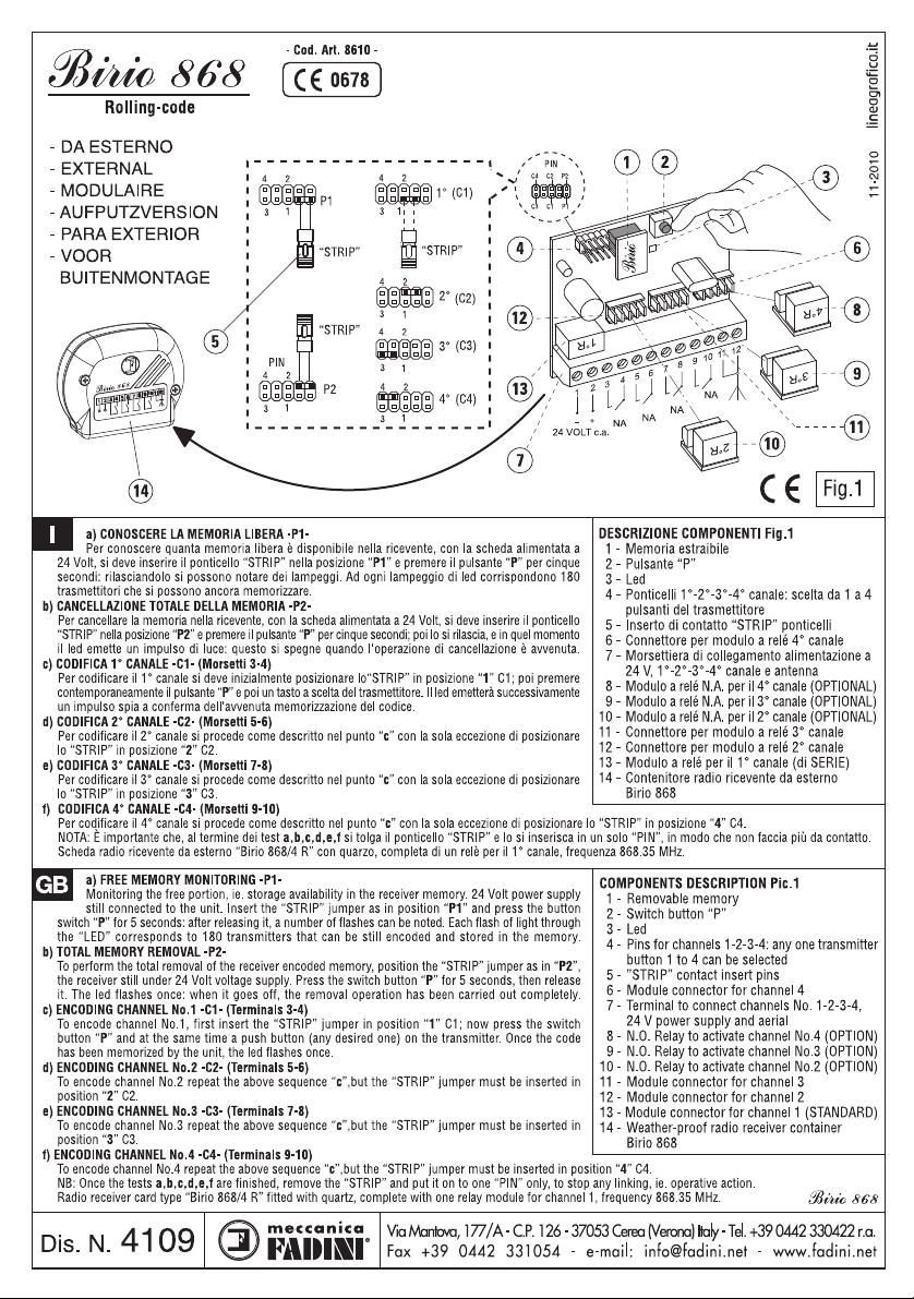
I
a) CONOSCERE LA MEMORIA LIBERA -P1-
Per conoscere quanta memoria libera è disponibile nella ricevente, con la scheda alimentata
a 24 Volt, si deve inserire il ponticello “STRIP” nella posizione “P1” e premere il pulsante “P”
per cinque secondi: rilasciandolo si possono notare dei lampeggi. Ad ogni lampeggio di led
corrispondono 180 trasmettitori che si possono ancora memorizzare.
b) CANCELLAZIONE TOTALE DELLA MEMORIA -P2-
Per cancellare la memoria nella ricevente, con la scheda alimentata a 24 Volt, si deve inserire il
ponticello “STRIP” nella posizione “P2” e premere il pulsante “P” per cinque secondi; poi lo si
rilascia, e in quel momento il led emette un impulso di luce: questo si spegne quando l’operazione
di cancellazione è avvenuta
c) CODIFICA 1° CANALE -C1- (Connettore innesto)
Per codificare il 1° canale si deve inizialmente posizionare lo “STRIP” in posizione “1” C1; si
deve premere contemporaneamente il pulsante “P” e poi un tasto a scelta del trasmettitore. Il
led emetterà successivamente un impulso spia a conferma dell'avvenuta memorizzazione del
codice.
d) CODIFICA 2° CANALE -C2- (Morsetti n°3-4-5)
Per codificare il 2° canale si procede come descritto nel punto “c” con la sola eccezione di posizionare lo “STRIP” in posizione “2” C2.
NOTA: è importante che, al termine dei test a,b,c,d, si tolga il ponticello “STRIP” e lo si inserisca in un solo “PIN”, in modo che non faccia più da
contatto.
Scheda ad innesto radio ricevente “Birio 868/2 R” con quarzo, completa di due moduli relè per il 1° e 2° canale, frequenza 868.35 MHz.
DESCRIZIONE COMPONENTI Fig.1
1 - Memoria estraibile
2 - Pulsante “P”
3 - Inserto di contatto “STRIP” ponticelli
4 - Ponticelli 1°-2° canale: scelta da 1 a 4
pulsanti del trasmettitore
5 - Led
6 - Relé per attivare il 2° canale
7 - Morsettiera di collegamento 2° canale contatto
N.C.-N.A. e antenna (morsetti 1-2)
8 - Connettore ad innesto femmina 1° canale e
alimentazione a 24 V
9 - Relé per attivare il 1° canale
10 - Programmatore elettronico serie Elpro
11 - Connettore ad innesto maschio
02-2009
GB
a) FREE MEMORY MONITORING -P1-
Monitoring the free portion, ie. storage availability in the receiver memory. 24 Volt power
supply still connected to the unit. Insert the “STRIP” jumper as in position “P1” and press the
button switch “P” for 5 seconds: after releasing it, a number of flashes can be noted. Each
flash of light through the “LED” corresponds to 180 transmitters that can be still encoded and
stored in the memory.
b) TOTAL MEMORY REMOVAL -P2-
To perform the total removal of the receiver encoded memory, position the “STRIP” jumper as
in “P2”, the receiver still under 24 Volt voltage supply. Press the switch button “P” for 5 seconds,
then release it. The led flashes once; when it goes off, the removal operation has been carried
out completely.
c) ENCODING CHANNEL No.1 -C1- (Plug-on connector)
To encode channel No.1, first insert the “STRIP” jumper in position “1” C1; now press the
switch button “P” and at the same time a push button (any desired one) on the transmitter.
Once the code has been memorized by the unit, the led flashes once.
d) ENCODING CHANNEL No.2 -C2- (Terminals 3-4-5)
To encode channel No.2 repeat the above sequence “c”,but the “STRIP” jumper must be inserted in position “2” C2.
NB: Once the tests a,b,c,d are finished, remove the “STRIP” and put it on to one “PIN” only, to stop any linking, ie. operative action.
Plug-in radio receiver card type “Birio 868/2 R” fitted with quartz, complete with two relay modules for channels 1 and 2, 868.35 MHz.
Via Mantova, 177/A - 37053 Cerea (Verona) Italy - Tel. +39 0442 330422 r.a.
Dis. N.
4110
®
Fax +39 0442 331054 - e-mail: info@fadini.net - www.fadini.net
COMPONENTS DESCRIPTION Pic.1
1 - Removable memory
2 - Switch button “P”
3 - “STRIP” contact insert pins
4 - Pins for channels 1-2: any one transmitter
button 1 to 4 can be selected
5 - Led
6 - Relay to activate channel No.2
7 - Terminal to connect N.O. n N.C. channel No.2
and aerial (Terminals 1-2)
8 - Female plug-on connector channel 1 and 24 V
power supply
9 - Relay to activate channel No.1
10 - Electronic programmer Elpro series
11 - Male plug-on connector
Page 4
a) CONNAITRE LA MEMOIRE LIBRE -P1-
F
Pour connaître combien de mémoire libre il y a dans le récepteur radio, avec la carte alimenté à 24 Volt, on doit
introduire le pontage “STRIP” dans la position “P1” et appuyer la touche “P” pour 5 secondes: ensuite on peut
noter des clignotements. Chaque clignotement de led correspond à 180 émetteurs qu’on peut encore mémoriser.
b) EFFACER TOTALEMENT LA MEMOIRE -P2-
Pour effacer totalement la mémoire d’un récepteur, et donc tous les émetteurs enregistrés, il faut que la carte
soit alimentée en 24 Volts. Vous devez ensuite insérer le pontage “STRIP” sur la position “P2” et actionner le
poussoir “P” pour 5 secondes, puis le relâcher. Ensuite, la led de signalisation émettra une impulsion lumineuse
qui s’éteindra quand l’opération d’effacement est terminée.
c) MEMORISATION 1
Pour rentrer le 1
moment sur le poussoir “P” du récepteur et puis sur une touche de l’émetteur. Lorsque le code est enregistré le
voyant “LED” s’allume pour confirmer la prise en compte du code.
d) MEMORISATION 2
Pour rentrer le 2
NOTE: Aprés les opérations a,b,c,d, il est important d’enlever le pontage “STRIP” et le mettre sur un seul “PIN”,
pour éviter des contacts.
Carte enfichable pour récepteur radio “Birio 868/2 R” à quartz complète de deux modules relais pour le 1er et le
ème
canal fréquence 868.35 MHz.
2
D
lang drücken: lässt man die Taste los, so kann man ein Blinken erkennen. Jedem Blinken des LEDs entsprechen
180 Handsender, die noch gespeichert werden können.
b) KOMPLETTES LÖSCHEN DES SPEICHERS -P2-
Um den gesamten codierten Speicher auf dem Funkempfänger zu löschen, den “STRIP” Codierbrücke in Position
“P2” stecken, wobei die Platine immer mit 24 Volt versorgt wird. Die Taste “P” muss 5 Sekunden lang gedrückt
werden, danach lässt man sie los, in diesem Moment sendet das LED einen Lichtimpuls, wenn der ausgeht, d.h.
dass der Löschvorgang erfolgt ist.
c) EINGABE 1. KANAL -C1- (Einsteckverbinder)
Um den 1. Kanal zu codieren, die “STRIP” Brücke in die Position “1” C1 stecken, danach die Taste “P” und
dann eine Taste des Handsenders (nach Wahl) gleichzeitig drücken. Dadurch wird die LED Signalleuchte aufleuchten,
wodurch uns die erfolgte Einspeicherung des Codes bestätigt wird.
d) EINGABE 2. KANAL -C2- (Klemmen 3-4-5)
Um dem 2. Kanal zu kodieren, wie oben Position “c” beschrieben vorgehen, die einzige Unterschied ist, dass
die “STRIP” Brücke in die Position “2” C2 gesteckt wird.
NB: Nachdem man die Test a,b,c,d durchgeführt hat, die “STRIP” Codierbrücke entfernen und sie in einen einzigen “PIN” stecken, damit er keinen Kontakt mehr macht.
Einsteck-Empfänger “Birio 868/2 R” mit Quarz komplett mit zwei Relaismodulen für den 1. und 2. Kanal, Frequenz 868.35 MHz.
E
relampagueos. Cada relampagueo de led señala que hay 180 transmisores que pueden memorizarse aun.
b) BORRADURA TOTAL DE LA MEMORIA -P2-
Se borra toda la memoria codificada en el receptor colocando el “STRIP” como un puente en la posición “P2”,
siempre estando alimentada la ficha misma a 24 Voltios. Se aprieta el pulsador “P” durante 5 segundos, se le
suelta y en aquel momento el led emite un impulso luminoso, que se apaga cuando la operación de borradura
se ha realizado.
c) CODIFICACION 1er CANAL -C1- (Conectador enchufable)
Para codificar el 1er canal, colocar ante todo el “STRIP” en la posición “1” C1; a continuación, apretar al mismo
tiempo durante 5 segundos el pulsador “P” y luego una tecla a elección del transmisor. El led emitirá después
una impulsión de luz para confirmar que el código ha sido memorizado.
d) CODIFICACION 2° CANAL -C2- (Borne 3-4-5)
Para codificar el 2° canal, actuar como reseñado en el apartado “c” excepto únicamente que se coloca el “STRIP”
en la posición “2” C2.
NOTA: es importante que al final de los ensayos a,b,c,d se quiete el puente “STRIP” y se lo introduzca en un
sólo “PIN”, de forma que el mismo no haga más contacto
Ficha enchufable radiorreceptor “Birio 868/2 R” con cuarzo, equipada de dos módulos relés para el 1er y el 2° canal, frequencia 868.35 MHz
NL
wordt losgelaten kunnen er flikkerlichten worden opgemerkt. Elk flikkerlicht van de lichtdiode komt overeen met
180 zenders waarin nog gegevens kunnen worden opgeslaan.
b) TOTALE ANNULERING VAN HET GEHEUGEN -P2-
Om het geheugen in de ontvanger te annuleren, met de kaart met een stroomtoevoer van 24 Volt, moet de “STRIP”
geleiderbrug op positie “P2” worden ingestoken en moet drukknop “P” gedurende vijf seconden worden ingedrukt;
hierna moet deze worden losgelaten en zal de lichtdiode op dat moment een lichtsignaal afgeven: deze gaat uit
wanneer de annuleringshandeling is uigevoerd.
c) CODERING 1e KANAAL -C1- (Koppelingsconnector)
Om het 1e kanaal te coderen moet de “STRIP” aanvankelijk op positie “1” C1 worden ingesteld: men moet
tegelijkertijd de drukknop “P” drukken en een toets van de zender naar keuze indrukken. De lichtdiode zal hierna
een verklikkersimpuls afgegeven ter bevestiging dat de code in het geheugen is opgeslaan.
d) CODERING 2e KANAAL -C2- (Klemmen 3-4-5)
Om het 2e kanaal te coderen moet men handelen zoals in punt “c” is beschreven met het enige verschil dat de
“STRIP” op positie “2” C2 moet worden ingesteld.
OPMERKING: Het is belangrijk dat na test a,b,c,d de “STRIP” geleiderbrug wordt weggenomen en dat men
deze in één “PIN” steekt zodat deze geen contact meer tot stand brengt.
Koppelingskaart ontvangstradio “Birio 868/2 R” met kwarts, compleet met twee relaismodules voor het 1e het 2e kanaal, frequentie 868.35 MHz.
er
CANAL -C1- (Connecteur enfichable)
er
canal, il faut d’abord mettre le pontage “STRIP” sur la position “1” C1; appuyer au même
ème
CANAL -C2- (Bornes 3-4-5)
ème
canal procéder de la même façon que ci-dessus en mettant le
a) PRÜFEN WIEVIEL PLATZ IM SPEICHER FREI IST -P1-
Um zu erfahren wieviel Platz in dem Speicher des Empfängers noch vorhanden ist, muss man bei mit 24
Volt gespeistem Modul die “STRIP” Codierbrücke in die Position “P1” einfügen und die Taste “P” 5 Sekunden
a) PARA CONOCER LA MEMORIA LIBRE -P1-
radiorreceptor, siempre estando la ficha alimentada a 24 Voltios, hay que conectar el puente “STRIP” en
la posición “P1” y apretar el pulsador “P” durante 5 segundos: soltandolo se pueden observar unos
a) OM HET VRIJE GEHEUGEN TE WETEN -P1-
beschikbaar is, met de kaart met een stroomtoevoer van 24 Volt, moet de “STRIP” geleiderbrug op positie
“P1” worden ingestoken en moet drukknop “P” gedurende vijf seconden worden ingedrukt; wanneer deze
pontage
“STRIP” sur la position “2” C2.
DESCRIPTION DES COMPOSANTS Fig.1
1 - Mémoire enfichable
2 - Poussoir “P”
3 - Pontage “STRIP”
er
4 - Ponts 1
émetteur de 1 à 4 max.
5 - Led
6 - Relais pour actionner le 2
7 - Borne de raccordement 2
N.F. et N.O. et antenne (bornes 1-2)
8 - Connecteur enfichable femelle 1
alimentation 24 V
9 - Relais pour actionner le 1
10 - Programmateur électronique série Elpro
11 - Connecteur enfichable mâle
BESCHREIBUNG DER BESTANDTEILEN Abb.1
1 - Abnehmbarer Speicher
2 - Schalter “P”
3 - “STRIP” Codierbrücke
4 - 1.-2. Kanal Anschlüsse: Wahl des
Sendersauslösers von 1 bis 4 max.
5 - Led
6 - Relais zur Steuerung des 2. Kanals
7 - Klemme 2. Kanal N.C. und N.O. Anschluss
und Antenne (Klemmen 1-2)
8 - Einsteckverbinder Mutter des 1. Kanals und
24 V Speisung
9 - Relais zur Aktivierung des 1. Kanals
10 - Elektronische Steuerung Serie Elpro
11 - Einsteckverbinder Zapfen
DESCRIPCION COMPONENTES Fig.1
1 - Memoria amovible
2 - Pulsador “P”
3 - Pieza de contacto “STRIP” puentes
4 - Puentes 1er y 2˚ canal: eleccion desde 2 hasta
4 pulsadores del transmisor
5 - Led
6 - Relé para activar el 2˚ canal
7 - Borne de conexion 2˚ canal contacto N.C.-N.A.
y antena (borne 1-2)
8 - Conectador enchufable hembra 1er canal y
suministro de corriente 24 V
9 - Relé para activar el 1er canal
10 - Programador electronico serie Elpro
11 - Conectador enchufable macho
BESCHRIJVING ONDERDELEN (FIG.1)
1 - Uitneembaar geheugen
2 - Drukknop “P”
3 - Inzetcontact “STRIP” geleiderbruggen
4 - Geleiderbruggen 1e -2e kanaal: keuze uit
1 tot 4 drukknoppen van de zender
5 - Led
6 - Relais om het 2e kanaal te activeren
7 - Verbindingsklem 2e kanaal normaal geopend-,
normaal gesloten contact en antenne (1-2)
8 - Vrouwtjes-koppelingsconnector 1e kanaal en
stroomtoevoer van 24 Volt
9 - Relais om het 1e kanaal te activeren
10 - Elektronische programmeereenheid Elpro serie
11 - Mannetjes-koppelingsconnector
ème
et 2
canal: choisir le poussoir
ème
canal
ème
canal contact
er
er
canal
canal et
Dis. N.
4110
Via Mantova, 177/A - 37053 Cerea (Verona) Italy -
®
Fax +39 0442 331054 - e-mail: info@fadini.net - www.fadini.net
Tel. +39 0442 330422 r.a.
Page 5
10-2010
Via Mantova, 177/A - C.P. 126 - 37053 Cerea (Verona) Italy - Tel. +39 0442 330422 r.a.
Fax +39 0442 331054 - e-mail: info@fadini.net - www.fadini.net
Page 6
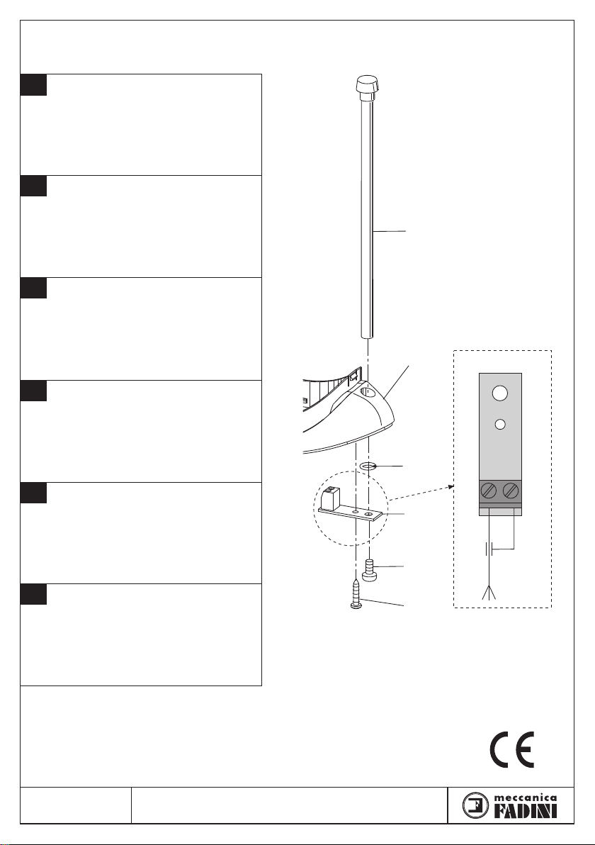
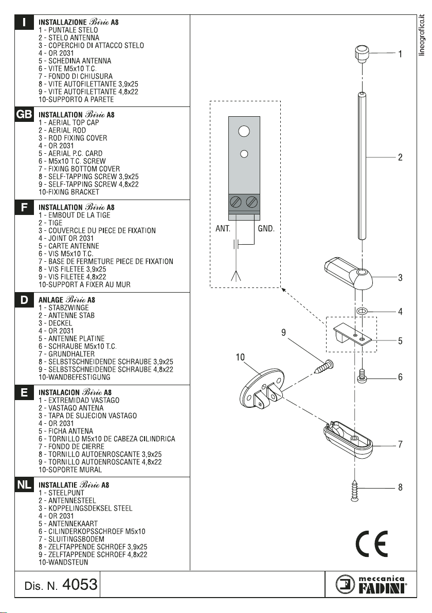
INSTALLAZIONE ANTENNA Birio A8
I
SUL LAMPEGGIATORE
1 - PUNTALE STELO
2 - COLLARE LAMPEGGIATORE MIRI 4
3 - OR 2031
4 - SCHEDINA ANTENNA
5 - VITE M5x10 T.C.
6 - VITE AUTOFILETTANTE
Birio A8 AERIAL FITTED TO THE
GB
FLASHING LAMP
1 - AERIAL ROD
2 - COLLAR OF FLASHING LAMP MIRI 4
3 - OR 2031
4 - AERIAL P.C. CARD
5 - M5x10 T.C. SCREW
6 - SELF-TAPPING SCREW
INSTALLATION ANTENNE
F
LA LAMPE DE SIGNALISATION
1 - TIGE
2 - COLLIER LAMPE DE SIGNALISATION MIRI 4
3 - OR 2031
4 - CARTE ANTENNE
5 - VIS M5X10 T.C.
6 - VIS FILETEE
EINBAU DER
D
BLINKLEUCHTE
1 - STAB
2 - SCHELLE BLINKLEUCHTE MIRI 4
3 - OR 2031
4 - ANTENNE PLATINE
5 - SCHRAUBE M5x10 T.C.
6 - SELBSTSCHNEIDENDE SCHRAUBE
INSTALACION DE LA ANTENA
E
EN EL DESTELLADOR
1 - VASTAGO
2 - COLLAR DESTELLADOR MIRI 4
3 - OR 2031
4 - FICHA ANTENA
5 - TORNILLO M5x10 DE CABEZA CILINDRICA
6 - TORNILLO AUTOENROSCANTE
INSTALLATIE
NL
MIRI 4 BLINKER
1 - STEELPUNT
2 - RAND MIRI 4 BLINKER
3 - OR 2031
4 - ANTENNE KAART
5 - CILINDERKOPSCHROEF M5x10
6 - ZELFTAPPENDE SCHROEF
MIRI 4
MIRI 4
Birio A8 SUR
Birio A8 ANTENNE AUF
MIRI 4
Birio A8
MIRI 4
Birio A8 ANTENNA OP DE
MIRI 4
1
2
3
4
ANT. GND.
5
6
Dis. N.
4036
Via Mantova, 177/A - C.P. 126 - 37053 Cerea (Verona) Italy - Tel. +39 0442 330422 r.a.
Fax +39 0442 331054 - e-mail: info@fadini.net - www.fadini.net
®
Page 7

GB
INSTALLATION MANUAL
FOR THE INSERTION OF THE CODE OF THE RADIO TRANSMITTER BIRIO 868
Made in Italy
Page 8

Page 9
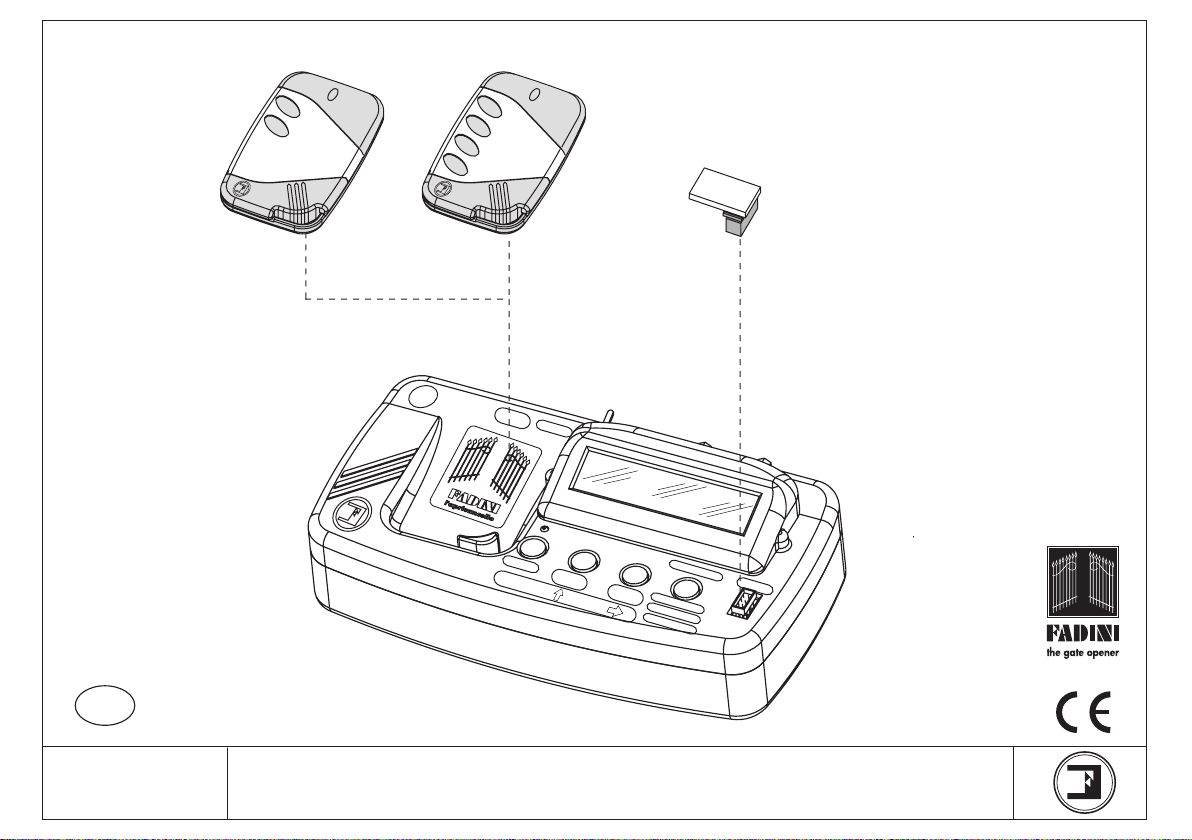
2 pushbutton
transmitter
Birio
Birio
4 pushbutton
transmitter
Birio 868
- ROLLING-CODE 868,35 MHz-
GB
GB
4213
Birio
LC
S
U
9
V
M
SELECT
CO
Birio
Removable
Memory
P
P
L
Y
O
L
T
ON/OFF
Birio LC Device
to key-encode radio receivers
and transmitters
EM
O
R
Y
ENTER
KEY
DE
DELETE
KEY
CO
PY
M
EM
O
R
REPLACE
DELETE
C
OPY
O
NE BU
TTO
N
Y
®
Made in Italy
Drwg. No. 4105
BIRIO 868 INSTRUCTIONS
Page 10

CONTENTS
CONTENTS ....................................................................................................................................................................................page 2
INTRODUCTION............................................................................................................................................................................page 3
EXTERNAL RADIO RECEIVER ENCODING OPERATION.........................................................................................................page 4
PLUG-IN RADIO RECEIVER ENCODING OPERATION.............................................................................................................page 5
RADIO RECEIVER FREE MEMORY READING ...........................................................................................................................page 6
RADIO RECEIVER MEMORY DELETING....................................................................................................................................page 7
TRANSMITTER COPYING ON THE SAME RECEIVER .............................................................................................................page 8
RADIO TRANSMITTER CODE DELETING..................................................................................................................................page 9
BIRIO LC” DEVICE (KEY-READING)...........................................................................................................................................page 10
- “BIRIO LC” DEVICE....................................................................................................................................................................page 11
- “BIRIO LC” DEVICE TYPES.......................................................................................................................................................page 12
- “BIRIO LC” DEVICE OPERATING.............................................................................................................................................page 13
- TRANSMITTER DATA READING .............................................................................................................................................page 14
- TRANSMITTER KEY ENCODING..............................................................................................................................................page 15
- TRANSMITTER KEY DELETING................................................................................................................................................page 16
- TRANSMITTER COPY................................................................................................................................................................page 17
- TRANSMITTER REPLACING.....................................................................................................................................................page 18
- TRANSMITTER DELETING FROM THE RADIO RECEIVER ...................................................................................................page 19
- COPY ONE BUTTON (COMMON BUTTON)............................................................................................................................page 20
- SELECT THE TRANSMITTER CODE.........................................................................................................................................page 21
- MEMORY DATA READING .......................................................................................................................................................page 22
- MEMORY KEY ENCODYING......................................................................................................................................................page 23
- MEMORY KEY DELETING..........................................................................................................................................................page 24
- MEMORY COPYING...................................................................................................................................................................page 25
- DIFFERENT INSTALLATIONS LEARNING ..............................................................................................................................page 27
- RADIO RECEIVER’S MULTIPLE LEARNING............................................................................................................................page 28
“BIRIO TOOL” PC SOFTWARE INSTALLATION AND USE.....................................................................................................page 29
- “BIRIO TOOL” SOFTWARE OPENING.....................................................................................................................................page 30
- MEMORY DATA DOWNLOADING...........................................................................................................................................page 31
- TRANSMITTER DATA DOWNLOADING.................................................................................................................................page 32
- TRANSMITTER CODE SEARCH................................................................................................................................................page 33
- TRANSMITTER COPYING.........................................................................................................................................................page 34
- TRANSMITTER REPLACEMENT..............................................................................................................................................page 35
- TRANSMITTER DELETING........................................................................................................................................................page 36
- COPY ONE BUTTON (COMMON BUTTON)............................................................................................................................page 37
- ADDING A TRANSMITTER TO THE MEMORY.......................................................................................................................page 38
DATA PRINTING...........................................................................................................................................................................page 39
BIRIO LC BATTERY RECHARGE..................................................................................................................................................page 40
BIRIO 868, BIRIO LC SPECIFICATIONS.....................................................................................................................................page 41
DIMENSIONS................................................................................................................................................................................page 42
2
Page 11
INTRODUCTION
Birio 868 Radio Receiver and Transmitter use a self-learning Rolling-Code technology: every time a button is pressed and a signal is emitted, the transmitter code is changed
at random by the system. Total security is so guaranteed.
Besides having the traditional Radio Transmitter and Receiver encoding procedure, Birio 868 both Transmitters and Receivers can be customized by the installer entering up
to two “keys” (that is 216 numerical codes) by means of a Birio LC Device. This customizing operation is not functional but it responds to the needs for an exclusive product.
The use of Birio LC device allows to create new transmitters with no need to operate directly on the installation.
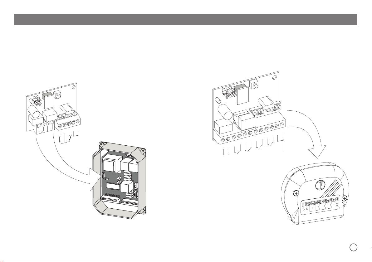
External Radio
Plug-in Radio Receiver
Receiver
Birio 868
1°R
Birio
2°R
Birio 868
Birio
- ROLLING-CODE-
1
2
3
4
5
AERIAL
1
–
24 VOLT a.c.
POWER SUPPLY
5
4
3
2
+
1st
CHANNEL
2nd
7
6
CHANNEL
8
3rd
CHANNEL
9
- ROLLING-CODE-
12
11
10
AERIAL
4th
CHANNEL
Control Pannel
External Radio
Receiver Case
Birio 868
3
Page 12
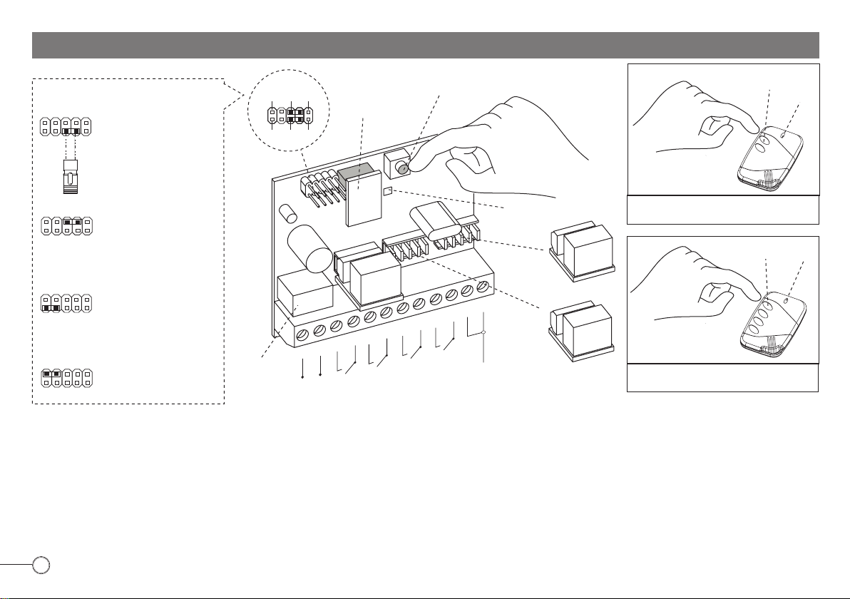
EXTERNAL
Birio 868
RADIO RECEIVER ENCODING OPERATION
PUSH BUTTON
LED
Birio
POSSIBILE PIN COMBINATIONS
24
Relay 1 -
1
1st channel
3
(C1)
PIN
C4 C2 P2
C3 C1 P1
REMOVABLEM
EMORY
BUTTON “P”
“STRIP”
JUMPER
24
Relay 2 -
1
2nd channel
3
(C2)
(C2)
Birio
LED
2 pushbuttons Birio
4°R
PUSH BUTTON
LED
2°R
1
–
24 VOLT a.c.
1°R
12
11
10
9
8
7
6
5
4
3
2
AERIAL
+
2nd
CHANNEL
1st
CHANNEL
3rd
CHANNEL
4th
CHANNEL
24
Relay 3 -
1
24
1
3rd channel
Relay 4 4th channel
3
3
(C3)
(C3)
(C4)
(C4)
RELAY
1st CHANNEL
POWER SUPPLY
SHOULD 24 V a.c. – 13 Vc.c. BE INTERRUPTED, THE CODE IS KEPT IN THE REMOVABLE MEMORY AND IT IS POSSILE TO INSERT IT INTO ANOTHER PC CARD.
1) Insert the removable Memory and supply the External Radio Receiver by connecting terminals 1(-) and 2 (+) to 24 V a.c. carry out connections of the N.O: contact to activate
the required channel.
2) Insert the “Strip” jumper into C1 position stimulating the 1R: relay corresponding to 3 and 4 terminals (1st Channel)
3) Press simultaneously P pushbutton on the Radio and any pushbutton on the transmitter you intend to operate as 1st Channel, for about 5 seconds. As storing confirmation
the red led will illuminate. Release the push button P and the push button on the transmitter.
4) Remove the “Strip” jumper and plug it into only one PIN.
5) For 2nd, 3rd and 4th channel storing, operate as above and plug the “Strip” jumper into the respective PINS (see picture) and the relays into the respective connectors
corresponding to the required channel.
RELAY
RELAY
3°R
Birio
4 pushbuttons Birio
4
Page 13
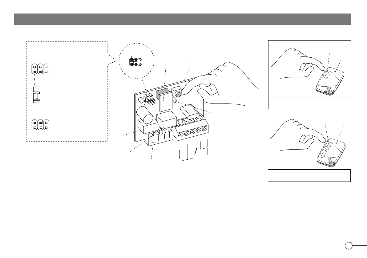
PLUG-IN
Birio 868
RADIO RECEIVER ENCODING OPERATION
POSSIBLE PIN COMBINATIONS
2
Relay 1 1st channel
1
(C1)
PIN
C2
C1
P2
P1
REMOVABLEME
MORY
PUSH
BUTTON “P”
PUSH BUTTON
LED
Birio
“STRIP”
JUMPER
Birio
2
Relay 2 2nd channel
1
(C2)
RELAY
1st CHANNEL
RELAY
2nd CHANNEL
TO FIT INTO CONTROL
PANNEL
1°R
+
–
2°R
4
5
2nd CHANNEL N.O.
OR N.C. CONTACTS
3
LED
1
2
AERIAL
2 pushbuttons Birio
PUSH BUTTON
Birio
LED
4 pushbuttons Birio
SHOULD 24 V AC – 13 V CC BE INTERRUPTED, THE CODE IS KEPT IN THE REMOVABLE MEMORY AND IT IS POSSILE TO INSERT IT INTO ANOTHER PC CARD.
1) Insert the removable Memory and supply the Plug-in Radio Receiver by plugging it into the control panel.
2) Insert the “Strip” jumper into C1 position stimulating the 1R: this corresponds to 3 and 4 terminals (1st Channel)
3) Press simultaneously P pushbutton on the Radio and any pushbutton on the transmitter you intend to operate as 1st Channel, for about 5 seconds. As storing confirmation
the red led will illuminate. Release the push button P and the push button on the transmitter.
4) Remove the “Strip” jumper and plug it into only one PIN.
5) For 2nd channel storing, operate as above and plug the “Strip” jumper into C2 (stimulating the 2R relay); connect the 2nd channel (NO or NC) then push the button on the
transmitter.
5
Page 14
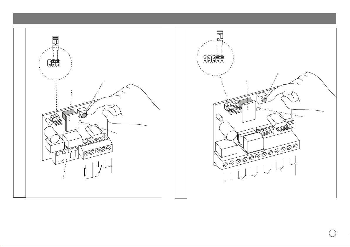
RADIO RECEIVER MEMORY READING
2
PIN
“STRIP”
JUMPER
1
(FREE MEMORY)
P1
REMOVABLE
MEMORY
PUSH BUTTON “P”
234
1
PIN
P1
“STRIP”
JUMPER
REMOVABLE
MEMORY
(FREE MEMORY)
PUSH BUTTON “P”
Birio
LED
Birio
1
2
AERIAL
LED
EXTERNAL RADIO RECEIVER
1°R
4
3
2
1
–
24 VOLT a.c.
POWER SUPPLY
+
1st
CHANNEL
5
6
2nd
CHANNEL
2°R
12
11
10
9
8
7
AERIAL
4th
CHANNEL
3rd
CHANNEL
PLUG-IN RADIO RECEIVER
1°R
TO FIT INTO
CONTROL PANEL
2°R
+
–
3
4
5
1) Insert the removable Memory and supply the External Radio Receiver with 24 V a.c. by terminals 1(-) and 2 (+) ; plug the Radio Receiver into the control panel.
2) Insert the “Strip” jumper into P1 position -free memory reading-.
3) Press P pushbutton on the Radio Receiver for about 5 seconds. Release the push button P and the red led will flash: every flash corresponds to 180 transmitters to store,
for ex: 7 flashes mean 7x180=1˙260 trasmitters still to store, (180 transmitters multipied by 10 flashes is 1˙800 transmitters to store).
4) Remove the “Strip” jumper and plug it into only one PIN.
6
Page 15
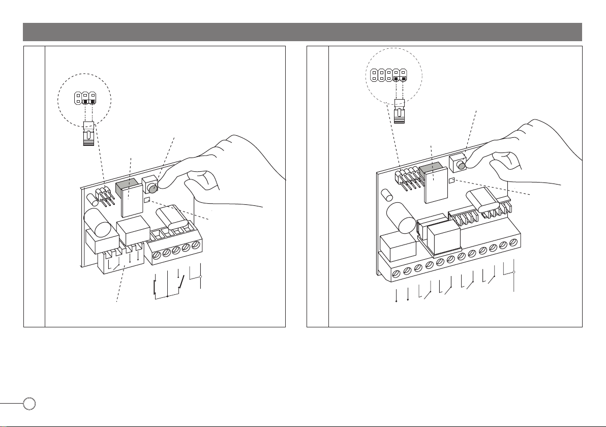
RADIO RECEIVER MEMORY DELETING
“STRIP”
JUMPER
2
PIN
1
(TOTAL MEMORY DELETION)
P2
REMOVABLE
MEMORY
PUSH BUTTON “P”
3
PIN
“STRIP”
JUMPER
24
1
(TOTAL MEMORY DELETION)
P2
REMOVABLE
MEMORY
PUSH BUTTON “P”
Birio
LED
Birio
2
AERIAL
LED
2°R
EXTERNAL RADIO RECEIVER
1
24 VOLT a.c.
POWER SUPPLY
1°R
12
11
10
9
8
7
6
5
4
3
2
1
AERIAL
–
+
1st CHANNEL
2nd CHANNEL
3rd CHANNEL
4th CHANNEL
1°R
2°R
PLUG-IN RADIO RECEIVER
+
–
TO FIT INTO
CONTROL PANEL
1) Insert the removable Memory and supply the External Radio Receiver with 24 V a.c. by terminals 1(-) and 2 (+) ; and plug the Radio Receiver into control panel.
2) Insert the “Strip” jumper into P2 position.
3) Press P pushbutton on the Radio Receiver for about 5 seconds. Release the push button P and the red led will illuminate: memory deleted.
4) Remove the “Strip” jumper and plug it into only one PIN.
3
4
5
7
Page 16

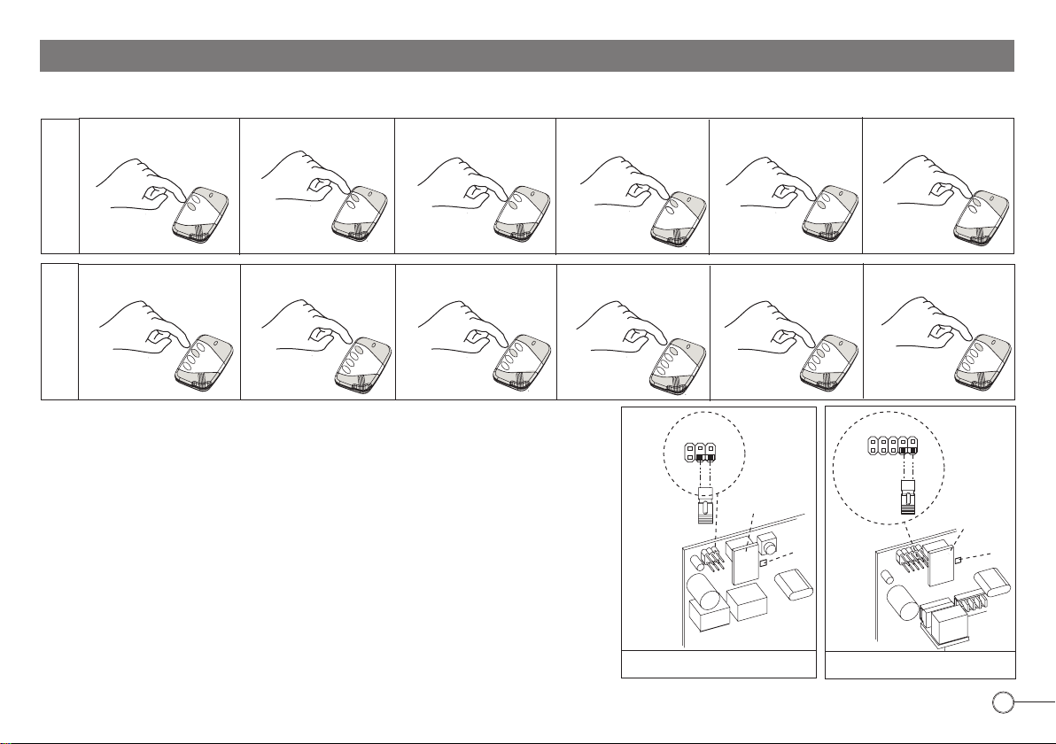
TRANSMITTER COPYING ON THE SAME RECEIVER
IMPORTANT: Transmitter copying is possible even if keys are encoded (see chapter about Birio LC device) provided that they were encoded by the same Birio LC encoding device.
Operations to be carried out in 30 seconds max time
New
A
2nd Operation
Push 1st button
and release when
the led turns off
B
3rd Operation
Push 2nd button
and release when
the led turns off
B
4th Operation
Push 1st button
2 buttons
Birio
and release
when the led
turns off
New
A
1st Operation
Push 2nd button and
release when the led
turns off plus 2 seconds
Operations to be carried out in 30 seconds max time
Push 1st button
and release
4 buttons
Birio
when the led
turns off
New
AA
Push 2ndt button and
release when the led
turns off plus 2 seconds
1st Operation
New
2nd Operation
Push 1st button and
release when the
led turns off
B
3rd Operation
Push 2nd button
and release when
the led turns off
B
4th Operation
TO COPY NEW TRANSMITTERS OPERATING ON THE SAME RADIO RECEIVER, YOU NEED TO HAVE AN ENCODED TRANSMITTER AND TO CARRY OUT
TWO OPERATIONS SEQUENCELY. THESE OPERATIONS MUST BE EFFECTED AT A MAX DISTANCE OF 10 METRES FROM THE RADIO RECEIVER, DULY
POWER SUPPLIED, AERIAL CONNECTED.
1st Operation: Push the 1st button on the new Radio Transmitter A and release when the Led turns off.
2nd Operation: Push the 2nd button on the new Radio Transmitter A as long as the Led turns off plus 2 seconds. Then release the button.
3rd Operation: Push the1st button on the encoded Radio Transmitter B and release when the Led turns off.
4th Operation: Push the 2nd button on the encoded Radio Transmitter B and release when the Led turns off.
Repeat these operations for any new Transmitter required.
8
Birio
2°R
1°R
3
4
5
PLUG-IN RECEIVER
Birio
0
1
9
8
7
6
5
4
3
2
1
–
+
4th
24 VOLT a.c.
POWER SUPPLY
CHANNEL
3rd
CHANNEL
2nd
CHANNEL
1st
CHANNEL
EXTERNAL RECEIVER
2
AERIAL
1
1
AERIAL
1
2
1
Page 17
RADIO TRANSMITTER CODE DELETING
IMPORTANT: Transmitter deleting is possible even if keys are encoded (see chapter about Birio LC device) provided that they were encoded by the same Birio LC encoding
device.
Push 2ndt button and release
when the led turns off
Push 1st button and release
when the led turns off
Push 2nd button and release
when the led turns off
Push 1st button and release
when the led turns off
Push 2nd button and release
when the led turns off
Push 1st button and release
when the led turns off
2 buttons
Birio
B
irio
B
irio
B
irio
2nd Operation 3rd Operation 4th Operation 5th Operation 6th Operation1st Operation
Push 2nd button and release
when the led turns off
4 buttons
Birio
Push 1st button and release
when the led turns off
B
irio
Push 2nd button and release
when the led turns off
B
irio
Push 1st button and release
when the led turns off
B
irio
2nd Operation 3rd Operation 4th Operation 5th Operation 6th Operation1st Operation
IF YOU NEED TO DELETE A TRANSMITTER CODE OPERATE AT A MAX DISTANCE OF 10 METRES
FROM THE RADIO RECEIVER, DULY POWER SUPPLIED, AERIAL CONNECTED.
Insert the removable “Strip” jumper on P1 position on the Radio Receiver:
1st Operation: Push the 2nd button on the Radio Transmitter and release when the Led turns off
2nd Operation: Push the 1st button on the new Radio Transmitter and release when the Led turns off
Repeat these 2 Operations for 6 times and end the sequence pushing the 1st button. Then Insert the
“Strip” jumper in only one PIN.
Repeat these operations for every transmitter you wish to delete.
N.B: IF THE NUMBER OF OPERATIONS OR THE TIME BEFORE NEXT PRESSING ARE MISTAKEN, YOU
MUST REPEAT THE OPERATIONS FROM THE BEGINNING, AND WAIT 1 MINUTE BEFORE STARTING
AGAIN.
B
irio
Push 2nd button and release
when the led turns off
B
irio
2
“STRIP”
JUMPER
PIN
P1
1
1°R
Relay
PLUG-IN RADIO RECEIVER
REMOVABLE
MEMORY
Birio
2°R
Relay
LED
B
irio
Push 1st button and release
when the led turns off
B
irio
24
PIN
“STRIP”
JUMPER
P1
1
3
Relay
EXTERNAL RADIO RECEIVER
REMOVABLE
MEMORY
Birio
B
irio
B
irio
LED
9
Page 18

BIRIO LC DEVICE (KEY-READING)
Birio 868 is a self-learning 868 Mhz frequency Radio Transmitter that can fit any gate automation installation with traditional enconding procedures. For a more professional
use any Birio 868 transmitter can be key-customized by the installer and the reseller using the Birio LC Device for key-encoding. This operation allows market and customers’
protection. A software for PC is supplied with the Birio LC Device as a tool to manage the key-customized installations.
NOTE: Keys can only be encoded by the Birio Devices, either before or after transmitter storing on the receiver provided that the key encodying operation is carried out on
both the transmitter and on the memory.
IMPORTANT: ONLY THE BIRIO LC DEVICE WHICH ENCODED THE KEY CAN CARRY OUT ALL STORING, COPYING AND DELETING OPERATIONS
10
2 buttons
transmitter
B
irio
B
irio
2 buttons
transmitter
Birio
G
B
S
T
R
O
M
V
E
R
S
G
O
U
R
N
-
G
9
V
O
L
T
EIN/AUS
Birio LC
S
P
E
I
C
H
E
R
C
O
D
E
W
Ä
H
L
E
N
Birio LC encoding device to
insert customizing keys
1st option ENCODING DEVICE ONLY IS USED
DUPLIZIEREN
S
C
H
L
Ü
S
S
E
E
I
L
N
G
E
B
E
N
SPEICHER
S
C
H
L
Ü
S
S
E
E
N
L
T
F
E
R
N
E
E
R
N
S
E
T
Z
E
N
L
Ö
S
C
H
E
N
E
I
N
E
T
A
S
T
E
K
O
P
I
E
R
E
N
Receiver plug-in
Memory
2 buttons
transmitter
B
irio
G
B
S
TR
O
M
V
E
R
S
G
O
U
R
N
-
G
9 V
O
LT
EIN/AUS
Birio LC
S
P
E
I
C
H
E
R
S
C
C
O
D
E
E
W
Ä
H
L
E
N
Birio LC encoding device to
insert customizing keys
2nd option Drwg. 4091 - ENCODING DEVICE WITH PC SOFTWARE USE
4 buttons
transmitter
B
irio
H
L
Ü
S
S
E
I
L
N
G
E
B
E
N
S
C
H
L
Ü
S
S
E
E
N
L
T
F
E
R
N
E
N
Receiver plug-in
Memory
Personal
Computer
Birio
DUPLIZIEREN
SPEICHER
E
R
S
E
T
Z
E
N
L
Ö
S
C
H
E
N
E
I
N
E
T
A
S
T
E
K
O
P
I
E
R
E
N
Software on
floppy disk
Page 19

POWER SUPPLY: Birio LC device has an internal rechargeable battery, 6 hours autonomy , you can also operate it by 230V 50Hz power supply using a 9V 300mA adaptor.
Maximum recharging time is 5 hours.
Serial cable Personal Computer connector
On/off switch
9 volt 300mA battery recharge connector
Display
Power supply led
Button for encoding operations and memory
Memory or transmitter key entering and code shifting
Transmitter and memory key deletion and code entering
Copy, replace, delete, copy 1 button of
the transmitter and the memory
To fit removable memory
GB
4213
SUPPLY
9 VOLT
Birio LC
ON/OFF
MEMORY
SELECT
CODE
ENTER KEY
DELETE KEY
COPY
REPLACE
DELETE
COPY ONE BUTTON
MEMORY
Drwg.4091
11
Page 20

BIRIO LC DEVICE TYPES
There are various kinds of Birio LC encoding devices belonging to different groups or families: Family A, Family B etc. distinguishable by an inner stamp), each one independent
from the other.
Every group is made up of two distinct Birio LC devices, each one having its own function (see picture referring to group A):
1) Master Device (Red)= enters only the 1st key and effects all operations on 1st key-encoded blank transmitters. It can also delete the 2nd key from slave devices belonging
to its family.
2) Slave Device (Blue)= enters only the 2nd key if the 1st one was encoded by the Master or Master/Slave belonging to the same family, and operates on 2nd key encoded
radio transmitters.
Once the Slave Device (for example an installer’s) has encoded the 2nd key, the Master Device will not be able to carry out any operation on those transmitters or memories,
but only the transmitter that stored the latest key will, in this case the Slave Device.
Please note that if you want to clear key-customized radio transmitters, you will have to delete the keys, by starting from the latest device that inserted the 2nd key, and then
the device that inserted the 1st. -repeat backwards the sequence stages in pictures-.
NOTE: Key encoding can be effected by Birio LC Devices either before or after transmitter storing into the receiver.
FAMILY
12
A
Birio
BLANK
Birio
1st KEY
2nd KEY
Birio
Birio
A
G
B
Birio
L
C
G
B
Birio
L
C
G
B
S
U
P
P
L
Y
9
V
O
L
T
O
N
/
O
F
F
Birio
L
M
E
C
M
O
R
I
A
I
N
S
S
E
E
L
R
E
I
S
Z
I
C
C
O
I
H
C
N
I
O
A
A
D
V
I
I
C
E
= MASTER
(RESELLER)
S
U
P
P
L
Y
9
V
O
L
T
O
N
/
O
F
F
M
E
M
O
R
I
A
D
U
P
L
I
C
I
N
A
S
S
E
E
L
R
E
I
S
Z
I
C
C
O
I
H
C
N
I
O
A
A
D
V
I
I
C
E
T
O
G
L
I
C
H
I
S
A
O
V
S
I
T
I
T
U
I
S
C
I
C
A
N
C
E
L
L
C
A
O
P
I
A
U
N
T
A
S
T
O
S
U
P
P
L
Y
9
V
O
L
T
O
N
/
O
F
F
M
E
M
O
R
I
A
D
U
P
L
I
C
I
N
A
S
S
E
E
L
R
E
I
S
Z
I
C
C
O
I
H
C
N
I
O
A
A
D
V
I
I
C
E
T
O
G
L
I
C
H
I
S
A
O
V
S
I
T
I
T
U
I
S
C
I
C
A
N
C
E
L
L
C
A
O
P
I
A
U
N
T
A
S
T
O
G
B
S
U
P
P
L
Y
9
V
O
L
T
O
N
/
O
F
Birio
D
U
P
L
I
C
A
M
E
M
O
R
I
A
T
O
G
L
I
C
H
I
S
A
O
V
S
I
T
I
T
U
I
S
C
I
C
A
N
C
E
L
L
C
A
O
P
I
A
U
N
T
A
S
T
O
Birio
1st KEY-CODE
A1
M
E
M
O
R
I
A
M
E
M
O
R
I
A
= SLAVE
(INSTALLER)
A
= MASTER
(RESELLER)
1st KEY
Birio
Birio
F
B
irio
L
M
E
C
M
O
R
I
A
I
N
S
S
E
E
L
R
E
I
S
Z
I
C
O
H
C
N
I
O
A
A
D
V
I
C
E
A1
= SLAVE
(INSTALLER)
G
B
Birio
L
C
= MASTER
A
(RESELLER)
D
U
P
L
I
C
A
C
I
M
E
M
I
O
R
I
A
T
O
G
L
I
C
H
I
S
A
O
V
S
I
T
I
T
U
I
S
C
I
C
A
N
C
E
L
L
C
A
O
P
I
A
U
N
T
A
S
T
O
Birio
Birio
1st KEY
2nd KEY
S
U
P
P
L
Y
9
V
O
L
T
O
N
/
O
F
F
M
E
M
O
R
I
A
D
U
P
L
I
C
I
N
A
S
S
E
E
L
R
E
I
S
Z
I
C
C
O
I
H
C
N
M
I
O
A
A
E
D
V
M
I
I
C
O
E
R
I
A
T
O
G
L
I
C
H
I
S
A
O
V
S
I
T
I
T
U
I
S
C
I
C
A
N
C
E
L
L
C
A
O
P
I
A
U
N
T
A
S
T
O
Birio
Birio
BLANK
Page 21

BIRIO LC DEVICE OPERATING
The Birio LC device has a practical and intuitive use, it does not allow the codification between the Radio Receiver and the Transmitter, but it can copy, replace and delete
both clear and key-encoded transmitters (provided that the keys were encoded by the same Birio Lc Device); and copy either blank or key-encoded Memories(provided that
the keys were encoded by the same Birio Lc Device).
Leds lighting on the Device will help during the operations. Every operation is carried out simply by pushing the corresponding button on the Device.
To return from mode Transmitter to mode Memory and viceversa simply turn off and turn on the Device. Remember that when the Device is turned off all received information
is cancelled. Therefore after turning the Device on and starting with the new operations it is necessary to send the information to the Birio LC Device of the transmitter
and the memory you need to operate in.
TRANSMITTER:
As soon as the Birio LC Device is switched on, it is in mode Transmitter; if the corresponding buttons are pushed all information about the key-codes and the family of the
Device will be displayed.
A Birio LC Device can read the data of a transmitter which was key-encoded by a Birio LC Device belonging to a different family. In this case the presence of the key and
and the type of Device that encoded the transmitter are displayed. If the message Error is displayed it means that the Birio LC Device did not read the transmitter information
and thus no operation can be carried out.
MEMORY: After switching on the Birio LC Device, push the Memory button (the first button on the left) and you enter Memory mode: all information about the key-codes and
the family of the Device will be displayed.
A Birio LC encoding Device can read the data of a Memory which was key-encoded by a Birio LC Device belonging to a different family. In this case the presence of the key
and and the type of Device that encoded the Memory are displayed.
If the message Error is displayed it means that the Birio LC Device did not read the Memory information and thus no operation can be carried out.
“BIRIO TOOL” PC SOFTWARE: The Birio LC Device can also be used as a support to the PC software for customers’ managing. Connect the Birio LC Device to the PC serial
port COM1, then open the software and turn on the Birio LC Device, click on connection and all the information (except the keys) of the Memory and the Transmitter will be
displayed.
13
Page 22

TRANSMITTER DATA READING
With this operation the Birio LC Device will read, recognize and display the Transmitter key-codes and the family they belong to.
If an “Error” message is displayed it means that the operation was not correctly carried out, or that the transmitter is encoded with a key-code belonging to a different
family.
SUPPLY
9 VOLT
ON / O
FF
9
V
O
SUPPLY
L
Switch on the Birio LC Device and the led will illuminate.
TRANSMITTER mode is immediately displayed.
1°
T
O
N
/O
F
F
OFF
Birio LC
M
EM
SELECTIONN
COD
ORY
ER
E
ON
Push any transmitter button and one of the following information will be displayed:
- No Key;
- 1 Key : Family...
2°
- 2 Keys: Family...
and then the transmitter code will be displayed
Return to mode transmitter.
All the following operations will refer to this transmitter whose information was read the last by the Birio LC Device.
3°
ENTER
KEYS
COPY
DELETE
KEYS
REPLACE
DELETE
C
O
P
Y
O
N
E
B
U
T
T
O
N
B
irio
DISPLAY
TRANSMITTER
DISPLAY
No Key
Transmitter Code:
00 20 D9
DISPLAY
TRANSMITTER
IMPORTANT: If during the 1st and the 2nd phase of this operation the button “Copy-Substitute-Delete-Copy 1 button” is pressed, the message “PRESS TRANSMITTER FIRST”
will be displayed.
14
Page 23

TRANSMITTER KEY ENCODING
Key-encoding must be carried out according to the family of the Birio LC Device.
- The Master Device (for ex. A) encodes clear Transmitters and Memories with the 1st key C1.
- The Slave Device (for ex. A1, A2,...) encodes only the 2nd key (C2) into those Transmitters and Memories which were 1st-key encoded by the Master Device belonging to
the same family.
If an “Error” message is displayed it means that the operation was not correctly carried out, or that the transmitter was key-encoded by a Birio device belonging to a different
family.
DISPLAY
DISPLAY
Follow the operation Transmitter data
1°
reading page 14.
B
irio
No Key
Transmitter code:
00 20 D9
TRANSMITTER
DISPLAY
Push the button Enter Key: “T- Enter Key” will be displayed, followed
2°
by “Enter Transmitter”.
Position the transmitter onto the Birio LC Device . When the led turns off the operation
is completed.
3°
N.W. If, when the led turns off, another transmitter is positioned, before TRANSMITTER
is displayed, it is possible to encode this second transmitter too.
MEMORY
SELECT
CODE
4213
COPY
ENTER
DELETE
KEYS
G
B
B
irio
Birio
LC
M
E
M
O
R
I
Y
E
N
S
E
L
E
C
K
T
E
C
O
D
E
REPLACE
KEYS
DELETE
COPY ONE BUTTON
C
O
P
Y
T
E
R
Y
S
M
E
M
O
R
Y
D
E
L
E
T
E
K
E
Y
S
R
E
P
L
A
C
E
D
E
L
E
T
E
C
O
P
Y
O
N
E
B
U
T
T
O
N
T - Enter Key
Enter transmitter
TRANSMITTER
IMPORTANT: When the operation is completed, check the transmitter information by following the operation “transmitter data reading” on page 14.
DISPLAY
15
Page 24

TRANSMITTER KEY DELETING
Key deleting operation can be carried out according to the Device family:
- The Master Device (for ex. A) can delete the 1st and the 2nd key to Transmitters and Memories which were encoded with keys beloging to the same family.
- The Slave Device (for ex. A1, A2,...) can delete only the 2nd key (C2) from those Transmitters and Memories which were encoded with the 1st and the 2nd key.
If an “Error” message is displayed it means that the operation was not correctly carried out, or that the transmitter is encoded with a key-code belonging to a different
family.
DISPLAY
Follow the operation transmitter data reading, page 14.
1°
Push the button Delete Key: the message “T- Delete Key” followed by “Enter Transmitter”
2°
will be displayed.
Position the transmitter onto the Birio LC Device . When the led turns off the operation is
completed.
3°
N.W. If, when the led turns off, another transmitter is positioned, before TRANSMITTER is
displayed, it is possible to delete the key to this second transmitter too.
MEMORY
SELECT
CODE
COPY
ENTER
DELETE
KEYS
GB
4
2
1
3
B
irio
Birio
LC
M
E
M
O
R
I
Y
E
S
E
L
E
C
K
T
C
O
D
E
REPLACE
KEYS
DELETE
COPY ONE BUTTON
C
O
P
Y
N
T
E
R
E
Y
S
M
E
M
O
R
Y
D
E
L
E
T
E
K
E
Y
S
R
E
P
L
A
C
E
D
E
L
E
T
C
E
O
P
Y
O
N
E
B
U
T
T
O
N
TRANSMITTER
DISPLAY
T - Delete Key
Enter Transmitter
DISPLAY
TRANSMITTER
IMPORTANT: When the operation is completed, check the transmitter information by following the operation “transmitter data reading” on page 14.
16
Page 25

TRANSMITTER COPY
Copying a Transmitter A means creating a new Transmitter B which, in order to be stored inside a Memory, uses an existing Transmitter A to enter Memory. Both transmitters
are different and have different codes.
This operation is possible with blank or key-encoded transmitters (in this case also the memory must be key-encoded).
If an “Error” message is displayed it means that the operation was not correctly carried out, or that the transmitter is encoded with a key-code belonging to a different
family.
DISPLAY
Follow the operation transmitter data reading, page 14, for the transmitter A to be copied.
NOTE: only Transmitter A code is needed for the copy,in this way it is possible to follow the
1°
operation as described on page 21.
Push the 4th multi-function button:the functions Copy, Replace,Delete and Copy one button
are sequencely displayed. To confirm press again this 4th button when the operation required
is displayed . Then position the transmitter B onto the Birio LC Device to learn the information
2°
to accomplish the operation.
Check the operation: remove transmitter B and press one button, the messages “Pulse
Transmission” and “Copy” will be displayed as a confirmation.
Transmitter A
to be copied
ENTER
MEMORY
KEYS
SELECT
CODE
DELETE
KEYS
A
COPY
REPLACE
DELETE
COPY ONE BUTTON
TRANSMITTER
DISPLAY
Copy
Transmitter
Enter Transmitter
Operate near the power supplied Radio Receiver (max distance 10 metres) and push
one button on transmitter B for 4-5 times as long as the led will illuminate.
3°
The operation completed, Transmitter B has accomplished its function.
B
Birio
2°R
1°R
1
2
3
4
5
AERIAL
A
B
Transmitter B
IMPORTANT: If by mistake a button on the transmitter B is pushed once or more times, before the Radio Receiver learning, or the operation is not correctly carried out,or
the same operation needs to be carried out on other installations (page 27), 4 more possibilities will be given to repeat the operation, if all the 5 possibilities are used up it is
possible to reactivate them by pressing the 1st button on the Transmitter for 20 seconds (after 5 seconds the led will turn off) , release when the Led will light again.
17
Page 26

TRANSMITTER REPLACING
Replacing a transmitter A means replacing it with a new one called transmitter B inside the Radio Receiver, using the Birio LC Device. When the operation is accomplished,
transmitter A will no longer be recognized by the Radio Receiver.
This operation is possible with blank or key-encoded transmitters (in this case the memory must be key-encoded too).
If an “Error” message is displayed it means that the operation was not correctly carried out, or that the transmitter is encoded with a key-code belonging to a different
family.
DISPLAY
Follow the operation transmitter data reading, page 14, for the transmitter A to be replaced.
1°
NOTE: only Transmitter A code is needed for the replacement,in this way it is possible to
follow the operation as described on page 21.
A
Transmitter A
to be replaced
TRANSMITTER
1
2
3
AERIAL
DISPLAY
Replace
Transmitter
Enter
Transmitter
A
B
Push the 4th multi-function button:the functions Copy, Replace,Delete and Copy one button
are sequencely displayed. To confirm press again this 4th button when the operation required
is displayed . Then position the transmitter B onto the Birio LC Device to learn the information
2°
to accomplish the operation.
Check the operation: remove transmitter B and press one button, the messages “Pulse
Transmission” and “Replace” will be displayed as a confirmation.
Operate near the power supplied Radio Receiver (max distance 10 metres) and push
one button on the transmitter B for 4-5 times as long as the led will illuminate.
3°
The operation completed, Transmitter B has accomplished its function.
MEMORY
SELECT
CODE
ENTER
KEYS
B
DELETE
KEYS
COPY
REPLACE
DELETE
COPY ONE BUTTON
Birio
2°R
1°R
4
5
Transmitter B
IMPORTANT: If by mistake a button on the transmitter B is pushed once or more times, before the Radio Receiver learning, or the operation is not correctly carried out,or the
same operation needs to be carried out on other installations (page 27), 4 more possibilities will be given to repeat the operation, if all the 5 possibilities are used up it is
possible to reactivate them by pressing the 1st button on the Transmitter for 20 seconds (after 5 seconds the led will turn off) , release when the Led will light again.
18
Page 27

TRANSMITTER DELETING FROM THE RADIO RECEIVER
Deleting a Transmitter A means deleting its key-code from the Radio Receiver, using the Birio LC Device as an alternative to operation on page 9. For this operation on the
Birio LC Device, any transmitter can be used (either clear or key-encoded), even the same transmitter, which will be used as a deleting “carrier B” to accomplish this operation
on the Radio Receiver.
When the operation is completed the Tansmitter “carrier B” will have deleted Transmitter A but will not replace it.
If an “Error” message is displayed it means that the operation was not correctly carried out, or that the transmitter is encoded with a key-code belonging to a different
family.
DISPLAY
Follow the operation transmitter data reading, page 14, for the transmitter A to be deleted.
1°
NOTE: only Transmitter A code is needed for the deletion,in this way it is possible to follow
the operation as described on page 21.
A
Transmitter A
to be deleted
TRANSMITTER
Push the 4th multi-function button:the functions Copy, Replace,Delete and Copy one button
are sequencely displayed. To confirm press again this 4th button when the operation required
is displayed . Then position the transmitter B(information carrier) onto the Birio LC Device
2°
to learn the information to accomplish the operation.
Check the operation: remove transmitter B and press one button, the messages “Pulse
Transmission” and “Delete” will be displayed as a confirmation.
Operate near the power supplied Radio Receiver (max distance 10 metres) and push
one button on transmitter B for 4-5 times as long as the led will illuminate.
3°
When the operation is achieved, Transmitter B has accomplished its function.
MEMORY
SELECT
CODE
Transmitter B
ENTER
KEYS
B
DELETE
KEYS
COPY
REPLACE
DELETE
COPY ONE BUTTON
DeleteTransmitter
Enter Transmitter
Birio
2°R
1°R
1
2
3
4
5
AERIAL
A
IIMPORTANT: If by mistake a button on the transmitter B is pushed once or more times, before the Radio Receiver learning, or the operation is not correctly carried out,or
the same operation needs to be carried out on other installations (page 27), 4 more possibilities will be given to repeat the operation, if all the 5 possibilities are used up it is
possible to reactivate them by pressing the 1st button on the Transmitter for 20 seconds (after 5 seconds the led will turn off) , release when the Led will light again.
19
DISPLAY
Page 28

COPYING ONE TRANSMITTER BUTTON (COMMON BUTTON)
This operation allows to copy one button of the transmitter, called common button for multiple users. In order to accomplish this operation a transmitter must have at least one
encoded button to be copied onto the radio receiver: for exemple if You need to copy only the 3rd button corresponding to the 3rd channel of the receiver of a Birio Transmitter
with all its 4 buttons codified, it is necessary to accomplish the operation pressing only the 3rd button.
Follow the operation transmitter data reading, page 14, for the transmitter A to be copied.
DISPLAY
NOTE: only Transmitter A code is needed to copy one button,in this way it is possible to follow
1°
the operation as described on page 21.
Transmitter
A
TRANSMITTER
whose common
button needs be
copied
Push the 4th multi-function button:the functions Copy, Replace,Delete and Copy one button are
sequencely displayed. To confirm press again this 4th button when the operation required is
displayed . Then position the transmitter B onto the Birio LC Device to learn the information to
2°
accomplish the operation.
Check the operation: remove the transmitter B and press one button, the messages “Pulse
Transmission” and “Copy one button” will be displayed as a confirmation.
Operate near the power supplied Radio Receiver (max distance 10 metres) and push one button on the
3°
transmitter B for 4-5 times as long as the led will illuminate.
MEMORY
SELECT
CODE
ENTER
KEYS
DELETE
KEYS
COPY
REPLACE
DELETE
COPY ONE BUTTON
DISPLAY
Copy one
transmitter button
Enter Transmitter
Birio
2°R
1°R
B
1
2
3
4
5
AERIAL
Transmitter B
IMPORTANT: If by mistake a button on the transmitter B is pushed once or more times, before the Radio Receiver learning, or the operation is not correctly carried out,or the same
operation needs to be carried out on other installations (page 27), 4 more possibilities will be given to repeat the operation, if all the 5 possibilities are used up it is possible to
reactivate them by pressing the 1st button on the Transmitter for 20 seconds (after 5 seconds the led will turn off) , release when the Led will light again.
20
Page 29

SELECT THE TRANSMITTER CODE
With the Birio LC device it is possible to carry out all operations i.e. Duplication,Replacement,Deletion and Copy of one button, by simply selecting the transmitter code from
a previously created codes archive.
All the operations will be carried out using a second transmitter B which will transmit the information to the Radio Receiver.
When the operation is completed this transmitter will have achieved its function.
Turn on the Birio LC device and the message TRANSMITTER
will be displayed.
1°
Push the 1st button “Select code” to enter transmitter
code dialling mode.
In this mode the two buttons in the center have both the
functions of increasing the numbers (2nd button from 0
2°
to F) and of shifting from one number to the other from
the left to the right (3rd button).
After dialling the code number, position the arrow under the
last number to the right and press the 1st button: the message
“TRANSMITTER” will then be displayed.Then press the 4th
3°
multifonction button and carry out the needed operation on
page 17, 18,19,or 20, starting from the 2° phase on.
ENTER
MEMORY
KEYS
SELECT
CODE
ENTER
KEYS
SELECT
CODE
DISPLAY DISPLAY
Cod.: 20 00 00
MEMORY
DELETE
DELETE
KEYS
KEYS
COPY
REPLACE
DELETE
COPY ONE BUTTON
COPY
REPLACE
DELETE
COPY ONE BUTTON
DISPLAY
Select code
Enter code
DELETE
SELECT
CODE
KEYS
Code.: 20 00 00
.
DISPLAY
TRANSMITTER
DISPLAY
Code.: 00 00 00
DISPLAY
Code.: 23 A0 F8
ENTER
KEYS
DELETE
KEYS
MEMORY
SELECT
CODE
COPY
REPLACE
DELETE
COPY ONE BUTTON
21
Page 30

MEMORY DATA READING
With this operation the Birio LC Device will read, recognize and display the Memory key-codes and the family they belong to.
If an “Error” message is displayed it means that the operation was not correctly carried out, or that the Memory is encoded with a key-code belonging to a different family.
Birio
Turn on the Birio LC device and plug-in the Memory; the
message TRANSMITTER will be displayed.
Press the 1st button “Memory” for at least 3 seconds: as
1°
an operating mode confirmation the message “MEMORY”
will be displayed.
DELETE
KEYS
COPY
REPLACE
DELETE
O
N
DELETE
KEYS
COPY
REPLACE
DELETE
COPY ONE BUTTON
COPY
MEMORY
ENTER
MEMORY
KEYS
E
B
U
T
T
O
N
SELECT
CODE
DISPLAY
MEMORY
Then all the information about the family type and the
2°
presence of any key-codes will be displayed.
22
DISPLAY
No key
DISPLAY
1 Key: A
DISPLAY
MEMORY
Page 31

EINGABE DES SCHLÜSSELS IN DEN SPEICHER
MEMORY KEY ENCODYING
Key-encoding must be carried out according to the family of the Birio LC Device.
- The Master Device (for ex. A) encodes clear Transmitters and Memories with the 1st key C1.
- The Slave Device (for ex. A1, A2,...) encodes only the 2nd key (C2) into those Transmitters and Memories which were 1st-key encoded by the Master Device belonging to
the same family.
If an “Error” message is displayed it means that the operation was not correctly carried out, or that the transmitter was encoded with a key-code belonging to a different
family.
Birio
DISPLAY
MEMORY
Follow the operation Memory data reading page 22.
1°
DELETE
KEYS
COPY
REPLACE
DELETE
O
N
DELETE
KEYS
COPY
REPLACE
DELETE
COPY ONE BUTTON
COPY
MEMORY
ENTER
MEMORY
KEYS
E
B
U
T
T
O
N
SELECT
CODE
Push the button Enter Key on the Birio LC Device: the message “M-Enter key 1” or
2°
“M-Enter key 2”, in case of Slave Device, will be displayed.
To confirm the operation follow “Memory data reading”
3°
operation page 22.
DELETE
KEYS
COPY
REPLACE
DELETE
O
N
DISPLAY
M - Enter key 1
MEMORY
SELECT
CODE
ENTER
KEYS
DELETE
KEYS
COPY
REPLACE
DELETE
COPY ONE BUTTON
Birio
DISPLAY
MEMORY
DELETE
KEYS
COPY
REPLACE
DELETE
COPY ONE BUTTON
COPY
MEMORY
ENTER
MEMORY
KEYS
E
B
U
T
T
O
N
SELECT
CODE
23
Page 32

MEMORY KEY DELETING
Key-deleting must be carried out according to the family of the Birio LC Device.
- The Master Device (for ex. A) can delete 1st and 2nd key-encoded Transmitters and Memories belonging to the same family.
- The Slave Device (for ex. A1, A2,...) can delete only the 2nd key (C2) from those Transmitters and Memories which were 1st and 2nd key-encoded.
If an “Error” message is displayed it means that the operation was not correctly carried out, or that the transmitter was encoded with a key-code belonging to a different
family.
Birio
DISPLAY
MEMORY
Follow the operation Memory data reading (page 22).
1°
DELETE
KEYS
COPY
REPLACE
DELETE
O
N
DELETE
KEYS
COPY
REPLACE
DELETE
COPY ONE BUTTON
COPY
MEMORY
ENTER
MEMORY
KEYS
E
B
U
T
T
O
N
SELECT
CODE
Push the button Delete Key on the Birio LC Device: the message “M-Delete key 1”
2°
or “M-Delete key 2”, in case of Slave Device, will be displayed.
To confirm the operation follow “Memory data reading”
3°
operation page 22.
DELETE
KEYS
COPY
O
24
REPLACE
DELETE
N
E
B
COPY
M - Delete
DISPLAY
ENTER
KEYS
DELETE
KEYS
REPLACE
DELETE
COPY ONE BUTTON
MEMORY
SELECT
CODE
Birio
DELETE
KEYS
COPY
REPLACE
DELETE
COPY ONE BUTTON
COPY
MEMORY
ENTER
MEMORY
KEYS
U
T
T
O
N
SELECT
CODE
Key 1
DISPLAY
MEMORY
Page 33

MEMORY COPYING
Birio 868 Memory is an important element in single or multiple installations because it stores the key-codes of many transmitters. For this reason, in order to grant security,
all memories can only be copied, while the Replacing and Deleting operations are not active.
Copying a Memory A means creating its copy Memory B together with all its stored codes, using the Birio LC Device.
This operation is possible with blank or key-encoded Memories.
If an “Error” message is displayed it means that the operation was not correctly carried out, or that the transmitter was encoded with a key-code belonging to a different
family.
Follow the operation Memory data reading (page 22).
1°
Memory A
DELETE
KEYS
COPY
REPLACE
DELETE
O
N
E
Birio
DISPLAY
DELETE
KEYS
COPY
REPLACE
DELETE
COPY ONE BUTTON
MEMORY
COPY
MEMORY
ENTER
MEMORY
KEYS
B
U
T
T
O
N
SELECT
CODE
Push the Copy button: the operation phases will
immediately be displayed. Wait for the rolling numbers
2°
from 10 to 0 to be finished before plugging in a new
Memory B.
Once the sequence has finished, the message “Insert
new Memory” will be displayed. Plug in the new Memory
3°
B and the rolling numbers 10 to 0 will be displayed.
DISPLAY
Copy Memory
DISPLAY
Insert new
Memory
DISPLAY
Read Memory
Memory Reading....
REPLACE
DELETE
O
N
Birio
COPY
MEMORY
E
B
U
T
T
O
N
Memory B
DELETE
KEYS
COPY
DISPLAY
10
0
DISPLAY
Push Button
25
Page 34

Push the Copy button.
4°
MEMORY
SELECT
CODE
ENTER
KEYS
DELETE
KEYS
COPY
REPLACE
DELETE
COPY ONE BUTTON
DISPLAY
DISPLAY
10
Copy...
0
As a confirmation “Memory Copied” will be displayed.
5°
26
DISPLAY
Memory copied
DISPLAY
MEMORY
Page 35

EINGABE DES SCHLÜSSELS IN DEN SPEICHER
DIFFERENT INSTALLATIONS LEARNING
This fonction allows a transmitter to be learned by receivers in different installations, simply by loading it with its information, i.e. Copy, Replacement, Deletion or the Common
Button, as described in the above chapters.
Procedure: After carrying out the needed operation, i.e. Duplucation, Remplacement, Deletion et Copy one button, as described in the above paragraphes, it is possible to
“load” transmitter B with the information received by the Birio LC Device, by pressing the 1st button on the transmitter and releasing it after 20 seconds (after 5 seconds the
led will turn off) when the led will illuminate again. Then operate near 2nd installationr (max distance 10 metres) and push 4-5 times a button in the transmitter B until the led
will illuminate.
In order to carry out the same operation on a 3rd installation, repeat the same transmitter “reloading” phase.
1° Installation
GB
4213
B
irio
Birio
LC
M
E
M
O
R
I
Y
C
O
P
Y
E
N
S
T
E
E
L
R
E
C
K
T
E
C
Y
O
S
D
E
D
E
L
E
T
E
K
E
Y
S
R
E
P
L
A
C
E
D
E
L
E
T
E
C
O
P
Y
O
N
E
B
U
T
T
O
N
Transmitter B receives the
information
M
E
M
O
R
Y
Transmitter B
Birio
Power supplied Radio
Push any button on Transmitter B for 4-5 times
until the led will illuminate
3° Installation
Transmitter B
Birio
To “reload” the transmitter:
press for 20 seconds et
release when the led
illuminates
Push any button on Transmitter B for 4-5 times
until the led will illuminate. When the operation
is achieved, Transmitter B will have
accomplished its function.
Repeat this operation for all the installations you need to encode.
Transmitter B
Birio
Birio 868
1st installation
Birio 868
Power supplied
Radio
3rd installation
2° Installation
Transmitter B
Birio
To “reload” the transmitter:
press for 20 seconds et
release when the led
illuminates
Push any button on Transmitter B for 4-5 times
until the led will illuminate. When the operation
isachieved, Transmitter B will have
accomplished its function.
4° Installation 5° Installation
Transmitter B
Birio
Power supplied Radio
irio
B
2°R
1°R
–
+
2nd installation
...
27
Page 36

RADIO RECEIVERS MULTIPLE LEARNING
It is possible to transmit the same information to many Radio Receivers at the same time without personally goint to the installation site but using a second transmitter B. To
accomplish this operation, power supply the Radio Receivers and effect all the Copying, Deleting, Replacing and Copying one common button operation, follow the phases
described in the respective chapters.
NOTE: The use of the “Professional Pratico” instrument can be useful to accomplish the operation.
GB
4213
Birio
Birio
LC
M
E
M
O
R
I
A
D
U
P
L
I
C
I
N
S
E
L
E
Z
I
O
C
N
O
A
D
I
C
E
A
S
E
R
I
S
C
C
I
H
I
A
V
M
E
I
M
O
R
I
A
T
O
G
L
I
C
H
I
S
A
O
V
S
I
T
I
T
U
I
S
C
I
C
A
N
C
E
L
L
C
A
O
P
I
A
U
N
T
A
S
T
O
Transmitter B receiving the
informations
Birio
2
°R
1
°R
Power supplied
Radio Receiver for
the 1st installation
Birio
Power supplied
Radio Receiver for
the 2nd installation
Birio
°R
2
°R
2
Power supplied
Radio Receiver for
Birio
the 3rd installation
B
irio
Power supplied
Radio Receiver for
the 4th installation
Transmitter B
28
Page 37

EINGABE DES SCHLÜSSELS IN DEN SPEICHER
“BIRIO TOOL” PC SOFTWARE INSTALLATION AND USE
Birio LC Device has its own PC software which is very helpful for customer managing. This software, called “Birio Tool” offers the possibility of memorizing and carrying out
all operations on transmitters-either blank or key-encoded by the same encoding device- even if the installer is not on the installation site.
Birio Tool software will not give any information about the precence of any key-code.
IMPORTANT: BEFORE CONNECTING YOUR PC TO THE BIRIO LC, MAKE SURE THAT THE PC HAS THE SERIAL PORT COM1, IF IT HAS THE USB PORT YOU NEED TO FORMAT
IT TO COM1.
“BIRIO TOOL” SOFTWARE INSTALLATION
- Create a new file called “Birio LC Device” in the working directory of your PC to contain all the working files.
- Insert the Floppy Disk into the PC and open it, then copy all the application files inside the newly created file.
- Oper the “Birio” aplication file.
- When opening the application file, a window with all the working options, will be displayed: then click on Open File and enter the name or the file of the customer: for ex.:
House , De Rossi jointly-owned building etc...
ATTENTION: Always open a new file for every installation or for every customer clicking on Open File.
2 buttons
transmitter
GB
4213
Birio LC
Birio LC device for customized key
encodying
4 buttons
transmitter
B
irio
B
irio
Birio
SUPPLY
9 VOLT
ON / OFF
MEMORIY
SELECT
CODE
COPY
ENTER
KEYS
DELETE
KEYS
REPLACE
DELETE
C
O
P
Y
O
N
E
B
U
T
T
O
N
Plug-in
Memory
Personal
Computer
MEMORY
Use an adaptor to connect
to USB port
“Birio Tool”
Floppy Disk software
29
Page 38

“BIRIO TOOL” SOFTWARE OPENING
For operating “Birio Tool” managing program always click on Open File and type the Customer’s name on the following window
To exit software click on Exit, this will automatically store the file.
Birio
Birio Tool
Transmitter
Receiver
Output
1
General informations
Customer’s name
2
3
4
Type file name
Type file name or file to open
OK
Cancel
Mario Rossi
Code number
<< Previous
Find
Customer
Find
Code
Enter to
Copy
Following >>
Entered or searched code (0,1,...F)
Enter to
Remplace
nr position
Add
Transmitter
Enter to
Delete
Print file
Delete
Transmitter
Print
List
Enter to
Copy one
button
Open file
Read
Memory
Connect
Open File
Exit
Made in Italy
File name
Connect to Birio LC
device
®
Exit and store file
30
Page 39

MEMORY DATA DOWNLOADING
-Connect your PC to the Birio LC device using an adaptor to USB port, turn on the Birio LC and open the “Birio Tool” file then click on “Open File” and enter the file name.
Birio
DISPLAY
D
- Turn on the Birio LC device, open the file and plug-in the Birio Memory.
- Click on the window “Connect”.
1°
- “PC OPERATIONS” will be displayed on the Birio LC as a connection
S
C
H
L
Ü
L
Ö
S
C
H
confirmation.
- Click on “Read Memory”: the codes of the Birio 868 Transmitters stored inside
the Memory will be displayed: the code is a sequence of numbers and letters made
up of 3 numbers of 2 figures each.
2°
- The Receiver’s channels and their respective buttons wil be displayed in the
Transmitter window.
IMPORTANT: Fill in the windows with the Customer’s Name and the General information for the operations you
3°
need to carry out and in order to have a Customers’ list with their corresponding Birio 868 transmitters.
ATTENTION: If the code number is made of letters and symbols beyond the series 1,2,...A, B,...,F (ex: §, ò, ü,...) it means that the data receiving is not correct and you need to
check the connecting cables and start back to download data.
ATTENTION: After this operation it is necessary to pay attention should you need to read the Memory data on PC (with the operation Memory data downloading on PC) because
when the file is closed, all the information entered by the the user will be overwritten and thus deleted, because it is not possible to write and store the Customer’s General
Information on the Memory.
UPLIZIER
SPEIC
H
S
S
E
L
ERS
E
N
ETZEN
LÖ
S
CHEN
EIN
E TA
STE KO
PIER
EN
ER
Connect
PC OPERATIONS
Click
Read
Memory
00 01 B5 03
Code number
<< Previous
Following>>
n° position
Click
Condominio via Garibaldi 17
general information
Mario Rossi
Customer’s name
31
Page 40

TRANSMITTER DATA DOWNLOADING
This operation allows to read a Birio 868 transmitter code on the Radio Receiver Memory, either with or without encoded keys, for better managing the Copying, Replacing
and Deleting operations.
- Connect your PC to the Birio LC device using a serial cable to port COM1, turn on the Birio LC and open the
“Birio Tool” file, then click on “Open File” and enter the file name.
1°
- Click on the window “Connect”.
- “PC OPERATIONS” will be displayed on the Birio LC as a connection confirmation.
- Click on “Read transmitter”.
2°
- Push one button on the Birio 868 transmitter.
The transmitter’s code which is a 6 figures number
will be displayed on the “Find Code” window.
- The Transmitter’s window will display the Birio 868
3°
Radio Receiver’s channels with the corresponding buttons.
- Ten fill in with the Customer’s General information.
ATTENTION: If the code number is made of letters and symbols beyond the series 1,2,...A, B,...,F (ex: §, ò, ü,...) it means that the data receiving is not correct and you need to
check the connecting cables and start back to download data.
Find
Customer
Find
Code
00 12 2F
Entered or searched Code (0,1,...F)
Connect
Click
Read
Transmitter
Click
Condominio via Garibaldi 17
General Informations
Mario Rossi
Customer’s name
DISPLAY
PC OPERATIONS
B
irio
32
Page 41

TRANSMITTER CODE SEARCH
The search for a Birio 868 transmitter inside a Memory file can be effected in three ways:
1) Type the code inside the window Code to enter or to find, if the code is not known it is possible to download it following the procedure “Transmitter data downloading” page
28; then click on Find Code.
2) Type the customer’s name inside the window Find Customer, and enter it.
3) Open a file and search the memory list by typing <<Previous or Following>>.
On the “Birio Tool” software
Find
Code
Enter code number
1)
For every transmitter in the list, the Customer’s general data and the channels activated by the corresponding transmitter buttons will be displayed.
Searched or entered Code(0,1,...F)
“Birio Tool” software
General
Information
Customer’s
name
Transmitter
code
Customer’s name
<< Previous
General information
Code number
On the “Birio Tool” software
Find
Customer
Enter customer’s name
2)
Following>>
“Birio Tool” software
Transmitter
1
2
3
4
to receiver
On the “Birio Tool” software
Code number
<< Previous
Search the list of the codified
3)
transmitters inside the Memory
Following>>
The channels
activated by the
corresponding
buttons will be
displayed
33
Page 42

TRANSMITTER COPYING
Copying a Transmitter A means creating a new Transmitter B which, in order to be coded inside a Memory, uses an existing Transmitter A to enter the Memory.
Both transmitters are different and have different codes.
For this operation it is also necessary to know the code of the transmitter to be copied following the operation “Find a transmitter’s code” page 33.
- Turn on the Birio LC device and open the file.
- Find the transmitter’s code inside the customer’s
list and page 33 and enter it into the Find Code
1°
window.
- Click on connect to Birio LC.
Find
Customer
Find
Code
Connect
00 12 2F
Entered or searched code(0,1,...F)
DISPLAY
PC OPERATIONS
Click
G
B
- Position the new Transmitter (the copy you want to get) onto the Birio LC Device.
2°
- Click on Enter code for Copying.
- When the Transmitter’s led turns off, the first part of the operation is completed.
- To activate the new transmitter get it near the Radio Receiver (max distance 10
metres) and push any button for 5 times: when the led will turn on the new transmitter
3°
is activated on the Radio Receiver.
4213
Birio LC
B
MEMORIY
SELECT
CODE
C
OPY
ENTER
KEYS
MEMO
RY
DELETE
KEYS
REPLACE
DELETE
C
O
P
Y
O
N
E
B
U
T
T
O
N
B
Power supplied
Enter code
for Copying
Click
Birio
2°R
1°R
5
Birio
B
A
1
2
3
4
AERIAL
B
Radio Receiver
IMPORTANT: If by mistake a button on the transmitter B is pushed once or more times, before the data transmission to the Radio Receiver, or the operation is not correctly
carried out, 4 more possibilities will be given to repeat the operation, if the 5 possibilities are used up, it is possible to reactivate them by pressing the 1st button on the
Transmitter for 20 seconds (after 5 seconds the led will turn off) release when the Led will light again.
34
Page 43

TRANSMITTER REPLACEMENT
The operation of replacing a Birio 868 Transmitter allows to replace an exiting transmitter with another one (either not encoded or key-encoded by the same Birio LC Device),
without making a copy of it. For this operation it is necessary to know the code of the Transmitter to be replaced by following the operation “Find a Transmitter code” page
33.
- Turn on the Birio LC device and open the file.
- Find the transmitter’s code inside the customer’s list
1°
on page 28 and enter it into the Find Code window.
- Click on connect to Birio LC.
-Position the new Transmitter B, which will replace the Transmitter A, onto the
Birio LC Device.
2°
- Click on Enter code for Replacement.
- When the Transmitter’s led turns off, the first part of the operation is completed.
- To activate the new transmitter get it near the Radio Receiver (max distance 10
metres) and push any button for 5 times: when the led will turn on the new transmitter
3°
is activated on the Radio Receiver.
Find
Customer
Find
Code
00 12 2F
Entered or searched code(0,1,...F)
G
B
4213
B
Birio LC
MEMORIY
ENTER
SELECT
KEYS
CODE
DELETE
KEYS
Connect
Click
Enter code
for
COPY
MEMORY
REPLACE
DELETE
C
O
P
Y
O
N
E
B
U
T
T
O
N
B
replacement
Click
Birio
2°R
1°R
4
5
Birio
B
A
1
2
3
AERIAL
B
Power supplied
Radio Receiver
IMPORTANT: If by mistake a button on the transmitter B is pushed once or more times, before the data transmission to the Radio Receiver, or the operation is not correctly
carried out, 4 more possibilities will be given to repeat the operation, if the 5 possibilities are used up, it is possible to reactivate them by pressing the 1st button on the
Transmitter for 20 seconds (after 5 seconds the led will turn off), release when the Led will light again.
35
Page 44

TRANSMITTER DELETING
Deleting a transmitter means cancelling an existing Birio Transmitter A by means of any Transmitter Birio 868 B (either not encoded or key-encoded by the same Birio LC Device),
which will not replace or be a copy of A. For this operation it is necessary to know also the code of transmitter A to be deleted following the operation "Find a transmitter's code"
page 33:
- Turn on the Birio LC device and open the file
- Find the transmitter's code inside the customer's list
1°
at page 33 and enter it into the Find Code window
- Click on connect to Birio LC
Find
Customer
Find
Code
-Position the new Transmitter "carrier B" (which will delete transmitter A) onto the
Birio LC Device.
2°
- Click on Enter code for Deletion
- When the Transmitter's led turns off, the first part of the operation is completed
- To delete the transmitter, get it near the Radio Receiver (max distance 10 metres) and
push any button for 5 times: when the led will turn on the transmitter B has deleted
3°
transmitter A on the Radio Receiver.
00 12 2F
Entered or searched code(0,1,...F)
G
B
4213
B
Birio LC
MEMO
RIY
ENTER
SELECT
KEYS
COD
E
COPY
DELETE
KEYS
REPLACE
DELETE
C
O
P
Y
O
N
E
B
U
T
T
O
Connect
Click
MEMORY
N
B
Power supplied
Enter code for
Deletion
Click
Birio
2°R
1°R
5
DISPLAY
PC OPERATIONS
B
1
2
3
4
AERIAL
Birio
A
Radio Receiver
IMPORTANT: If by mistake a button on transmitter B is pushed once or more times, before the data transmission to the Radio Receiver, or the operation is not correctly carried
out, 4 more possibilities will be given to repeat the operation, if the 5 possibilities are used up, it is possible to reactivate them by pressing the 1st button on the Transmitter for 20
seconds (after 5 seconds the led will turn off) release when the Led will light again.
36
Page 45

COPY ONE BUTTON (COMMON BUTTON)
With this operation it is possible to copy one button of the transmitter, called Common Button, for multiple automatic gates or garage doors. Before carrying out the operation,
the transmitter needs to be encoded with at least 1 button to be copied on the Radio Receiver: for exemple if you need to copy only the 3rd button corresponding to the 3rd
channel of the receiver of a Birio 868 transmitter which has the 4 buttons codified, it is necessary to complete the operation on the new transmitter by pushing the 3rd button.
- Turn on the Birio LC device and open the file.
- Find the transmitter code inside the customer’s list
1°
and page 33 and enter it into the Find Code window.
- Click on connect to Birio LC.
Find
Customer
Find
Code
- Position the Transmitter, whose button you need to activate, onto the Birio LC Device
- Click on Enter to copy one button.
2°
- When the lTransmitter’s led turns off, the first part of the operation is completed.
- To activate the transmitter, get it near the Radio Receiver (max distance 10 metres)
and push only the button you need to operate as Common Button for 5 times: when the
3°
led will turn on the transmitter is activated on the Radio Receiver.
00 12 2F
Entered or searched code(0,1,...F)
G
B
4213
B
Birio LC
M
EMORIY
ENTER
SELECT
KEYS
CODE
COPY
DELETE
KEYS
REPLACE
DELETE
C
O
P
Y
O
N
E
B
U
T
T
O
N
Connect
Click
MEMORY
B
Power supplied
Enter to copy
one button
Click
Birio
2°R
1°R
5
DISPLAY
PC OPERATIONS
B
1
2
3
4
AERIAL
Birio
B
irio
Radio Receiver
IMPORTANT: If by mistake a button on the transmitter B is pushed once or more times, before the data transmission to the Radio Receiver, or the operation is not correctly
carried out, 4 more possibilities will be given to repeat the operation. If the 5 possibilities are used up, it is possible to reactivate them by pressing the 1st button on the
Transmitter for 20 seconds (after 5 seconds the led will turn off) and releasing it when the Led will light again.
37
Page 46

ADDING A TRANSMITTER TO THE MEMORY
EINEN FUNKHANDSENDER ZUM SPEICHER HINZUFÜGEN
This operation allows to add a new transmitter to the Memory file, and then store it without unplugging the Memory from the Radio Receiver .
- Turn on the Birio LC Device and open the file.
- Click on connect.
1°
- Click on Add Transmitter.
- Fill in the Code Number of the new Transmitter (see page 32 on
how to download the transmitter’s data and the code) then fill in
the general information.
- Follow Transmitter Copying operaton (page 34 starting from 2nd phase) entering the
code of a key-encoded Transmitter into Memory, this will allow the new Transmitter to
2°
enter Memory.
Connect
Click
Find
Customer
Find
Code
2
nr position
Add a
transmitter
00 E6 69
Delete a
transmitter
00 12 2F
Entered or searched code(0,1,...F)
<< Previous
Code number
Following >>
Enter code
for copy
Click
- To activate the new transmitter get it near the Radio Receiver (max distance 10
metres) and push any button for 5 times: when the led will turn on the new transmitter
3°
is activated on the Radio Receiver.
B
Birio
2°R
1°R
1
2
3
4
5
AERIAL
A
B
N.W: After this operation it is necessary to pay attention should you need to read the Memory data on the PC (with the operation Memory data downloading on PC, page 31)
because when the file is closed, all the information entered by the the user will be overwritten and thus deleted, as it is not possible to write and store the Customer’s General
Information on the Memory.
38
Page 47

DATA PRINTING
For better managing the stored data in the “Birio Tool” programme, we suggest to print every stored file and keep them in your records.
Before printing, choose a software for opening the file for ex “Word by office”.
IMPORTANT: Always remeber to fill in all data about the customer, in this way you will have all the complete information printed.
General information
Immeuble Marinella
Mario Rossi 655A79 0001
Giulio Bianchi 0001B2 0211
Custromer’s name
Birio 868
transmitter code
Activated channels to
buttons
4° 3° 2° 1°
39
Page 48

Birio
Birio LC Device with its own internal battery has 6 hours autonomy, when the battery needs to be recharged the letters “b L” = “battery low” are displayed, then all leds will
start to flash.
Plug-in the battery recharger and recharge for about 5 hours. NOTE: the battery recharger is not supplied with the Device. When buying one make sure it is suitable with the
batteries technical data.
Plug in the battery recharger as soon as the Display dims so that you can work with the Device supplied by the mains.
LC BATTERY RECHARGE
DISPLAY
LOW BATTERY
system
230 V
50Hz
4213
Recharger
9V a 300mA
40
Page 49

Birio 868
, BIRIO LC SPECIFICATIONS
TRANSMITTER
Working Frequency................................................................................................868,35 MHz
Frequency Tolerance................................................................................................± 150 KHz
Radiated Power.............................................................................................................100 µW
Band width ....................................................................................................................>25 KHz
Apparent power of harmonic products...................................................<-54 dBm (<4µW)
Power supply ................................................................................6 Vcc (2 batteries CR2032)
Average absorption.........................................................................................................14 mA
Working temperature..........................................................................................-40° C +85° C
Number of channels......................................................................................................2 and 4
Transmission range ................................................................................................120 metres
Codification...................................................DIGITAL(2
64
Chriptographic) “Rolling-Code”
RADIO RECEIVER
Working Frequency................................................................................................868,35 MHz
Memory space ............................................................................................1˙800 transmitters
Sensitivity (to working pulse)........................................................................................> 1 µV
Signal range.............................................................................................................120 metres
AC POWER SUPPLY.......................................................................................24 VAC (+/-10%)
CC AC POWER SUPPLY.. ..........................................................................13 VCC (+20% -5%)
Working absorbtion......................................................................28 mA (1° active channel)
Stand-by absobtion .........................................................................................................14 mA
Codification...................................................................................................................DIGITAL
Number of channels......................................................................................................2 and 4
Relay Contact......N.0.(1°,2°,3°,4° external channel) - N.O. ou N.C.(2° Plug-in channel)
Relay Contact rating ........................................................................................0,5 A - 125 Vca
Excitation time ...............................................................................200 ms (1 complete code)
Dropout time ......................................................................300 ms (from the last valid code)
Working temperature ..........................................................................................-10° C +55°C
BIRIO LC DEVICE
Max absorbtion.....................................................................................................40 mA
Average absorbtion .............................................................................................25 mA
Autonomy ............................................................................................................6 hours
Time battery recharge.......................................................................................5 hours
Radiated power....................................................................................................80 µW
Reception Sensitivity (to working pulse).............................................................1 µV
NiMh battery pack (n°8 rechargeable).................................................9,6 V 250 mA
Display .........................................................................................................16x2 figures
GB
SUPPLY
9 VOLT
4213
Birio LC
Birio
Birio
Birio
2
Birio
2°R
1°R
1
2
3
4
5
AERIAL
24 VOLT AC
POWER SUPPLY
4
3
2
1
–
+
1°
CHANNEL
1
1
1
0
1
9
8
7
6
5
AERIAL
4°
CHANNEL
3°
CHANNEL
2°
CHANNEL
ON / OFF
M
E
M
O
R
IY
S
E
LE
C
T
C
O
D
E
Birio 868
868 MHz “Rolling-Code”
C
O
P
E
N
K
E
Y
T
E
R
Y
S
D
E
L
E
T
E
K
E
Y
R
S
E
P
L
A
C
E
D
E
LE
T
E
COPY ONE BUTTON
0678
Made in ITALY
M
E
M
O
R
Y
“BIRIO TOOL”SOFTWARE:
Operating Systems: Windows ‘98; Windows 2000; Windows Millennium; Windows XP.
41
Page 50

BIRIO 868, BIRIO A8, BIRIO LC DIMENSIONS
42
93
Birio
10
68
43
2 channel Birio 868
transmitter
- weight 23 g
180
GB
S
U
P
P
L
Y
4213
Birio LC
9
V
O
L
T
O
N
/
O
F
F
M
E
M
O
R
I
Y
E
N
S
T
E
E
L
R
E
C
K
T
E
C
Y
O
S
D
E
C
O
P
Y
M
E
M
O
R
D
E
L
E
T
E
K
E
Y
R
S
D
E
CO
PY ONE BUTTON
Y
E
P
L
A
C
E
L
E
T
E
Device to key-encode transmitters
and receivers - weight 340 g
44
60
10
4 channel Birio 868
transmitter
- weight 23 g
27
Birio
43
Birio 868
91
External Radio
Receiver case -
weight 68 g
68
73
36
60
70
Aerial Birio A8 -
weight 63 g
210
Page 51

Page 52

Page 53

Page 54

 Loading...