

Page 1

APROLI 280 BATT
External oil-hydraulic operator for
swinging gates with very large pillars
Oil-hydraulic operator fitted with articulated arm
Hydraulic driving force adjustment
Two-way locking
Instruction manual
GB
Page 2

APROLI 280 BATT
CUTAWAY VIEW OF THE ELECTRIC MOTOR ASSEMBLY AND
HYDRAULIC JACK
AVAILABLE TYPES: NON LOCKING - LOCKING - WITH FLOW REGULATOR
TWO-WAY LOCKING
VALVE ASSEMBLY
PRESSURE SAFETY
VALVE “CLOSE”
GREEN
PRESSURE SAFETY
VALVE “OPEN”
RED
OIL RESERVOIR
TERMINAL PLUG
COVER
“C” “A”
“B”
TERMINAL PLUG
EARTH WIRE
OIL RESERVOIR
REAR CAP
0.25 HP
ELECTRIC MOTOR
HYDRAULIC LOBE
PUMP
JACK END CAP
st
PISTON
1
RACK
RELEASE LEVER
PISTON LINER
SHAFT SUPPORT
SQUARE INDENTED
SHAFT
nd
PISTON
2
PISTON LINER
MAIN ASSEMBLY
BLOCK WITH MOTOR
AND HYDR. JACK
®
PIC. 1
2
Page 3

INSTRUCTIONS FOR THE INSTALLATION OF APROLI 280 BATT TO SWINGING DOUBLE GATES WITH VERY
LARGE PILLARS
it is recommended to follow these instructions to achieve a perfect application of the operator.
BASE AND
FIXING BRACKET
STUD
BOLT
ASSEMBLY ELEC.
MOTOR HYDR. JACK
PROTECTION
COVER
FIXING
SCREWS
Lh
RETAINING
OPEN STOP ASSEMBLY
14 E22 NUT, STUD BOLT,
ADJUSTER COVER.
LEFT-HAND WASHER Ø 8.5
8M E13 NUT
GRUB SCREW
PIC. 2
First loosen the fastening screws to remove the cover. To do this, open the hinged door with the supplied key; one of the two fastening
screws is there. After the removal of the cover, the electro-hydraulic assembly is fully exposed, ie. “electric motor/hydraulic jack” fitted
with the pressure safety valves that control the thrust/pushing power of the operator and the emergency release in events like power
failure. It also includes a bracket, designed to provide fixing facility to a wall or pillar and a suitable outlet for the cables; an articulated
arm, adjustable to meet the most various distance requirements on site applications; and a shoe bracket to be fixed to the gate. The
operator is supplied already pre-filled with special oil to suit both high and low environment temperatures. It allows the correct performance
of APROLI 280 BATT within a temperature range from –20°C to +80°C. APROLI 280 BATT is produced and tested in the workshops of
MECCANICA FADINI which guarantees the long lasting reliability of this product in time.
DRIVING
BENDED
ARM
BENDED ARM
PLUG PROFILE
BOLT AND
NUT
STRAIGHT
ARM COVER
ARTICULATED ARM
LEFT-HANDED
SCREW FOR
ADJUSTMENT
STRAIGHT
ARM.
ADJUSTABLE
BUSH
FIXING
SHOE
®
3
Page 4

HOW TO FIX APROLI 280 BATT TO A PILLAR BY EXPANDING BOLTS OR SCREWS
Before fitting the operator APROLI 280 BATT to the gate, make sure that the gate structure is adequate to be electrically operated and
that is strong enough to bear the mechanical stress of automatic operations and is well built and smooth running.
It is recommended to reinforce the gate and fix the metallic parts which may not work properly, do the necessary to prevent or correct
friction of the gate against the pavement or pillar (this must particularly apply to the gate hinges).
VERY LARGE PILLAR
WHERE THE GATE
HINGE IS FIXED
IN THE MIDDLE
4 EXPANDING
BOLTS
MAINS SUPPLY
ELECTRIC CABLE
FIXING
BRACKET
NUTS WITH
WASHERS
GATE LEAF
LEVEL
PIC. 3
ARTICULATED
ARM
OPERATOR
COVER
Fix the bracket to the pillar and bring the electric cable to the most suitable position so that the fixing of the articulated arm is allowed
to coincide with a solid crossing bar of the gate leaf. The shoe bracket is to be bolted or welded to the gate at a suitable distance which
is set after the first manual tests. (Release lever B page 10)
DISTANCE
The distance from gate pivot center to arm bolt
center is to be calculated through manual
operations of the gate before fixing the shoe
bracket. The distances on page 6-7 are merely
an application example.
COMPLETELY INSTALLED
UNIT. LEFT-HANDED
MODEL
ANTI-CRUSH DESIGN
ARTICULATED ARM
FOR SAFETY
APROLI 280 BATT is easy to install. It can be supplied either fitted with hydraulic locking device for gates up to 2 m width, or without
hydraulic locking with an electric lock for gates up to 5 m.
®
4
PIC. 4
Page 5

APPLICATION OF TWO APROLI 280 BATT ON TO A DOUBLE SWINGING GATE. 90° OPENING.
The recommended maximum gate width with APROLI 280 is 5 m. The locking type operator is recommended up to 2 m gate width. Beyond
2 m a lock is required to be fitted to the gate and the non locking type operator is advisable.
2 m 2 m
LEFT-HAND
GATE STOP IN
OPEN GATE
POSITION
PIC. 5
LEFT-HAND
ARTICULATED
ARM
GATE STOP
IN CLOSE GATE
90° 90°
POSITION
RIGHT-HAND
ARTICULATED
ARM
It is recommended that suitable gate stops are always fitted to
the system both in open and close gate positions.
OVERTURN
RIGHT-HAND
GATE STOP IN
OPEN GATE
POSITION
BOTH
Rh Lh
RIGHT-HAND
ARTICULATED
ARM
GRUB
SCREW
ELECTRIC MOTOR/HYDRAULIC
JACK ASSEMBLY
Rh AND Lh
LEFT-HAND
ARTICULATED
ARM
GRUB
SCREW
SQUARE
SECTION
SHAFT
REFERENCE
SEAT
PIC. 6
Both right-hand and left-hand applications are possible just by turning over the articulated arm and fitting it to the square section shaft
of the operator. Tighten the retaining pin in its seat to fix the arm to the shaft. The assembly ie. motor/jack, fixing bracket and cover are
designed to suit both right and left-hand applications with the same method of installation.
Important: the articulated arm must be fixed so that it pushes against the gates and keeps them well pressed on to the close
position gate stop.
®
5
Page 6

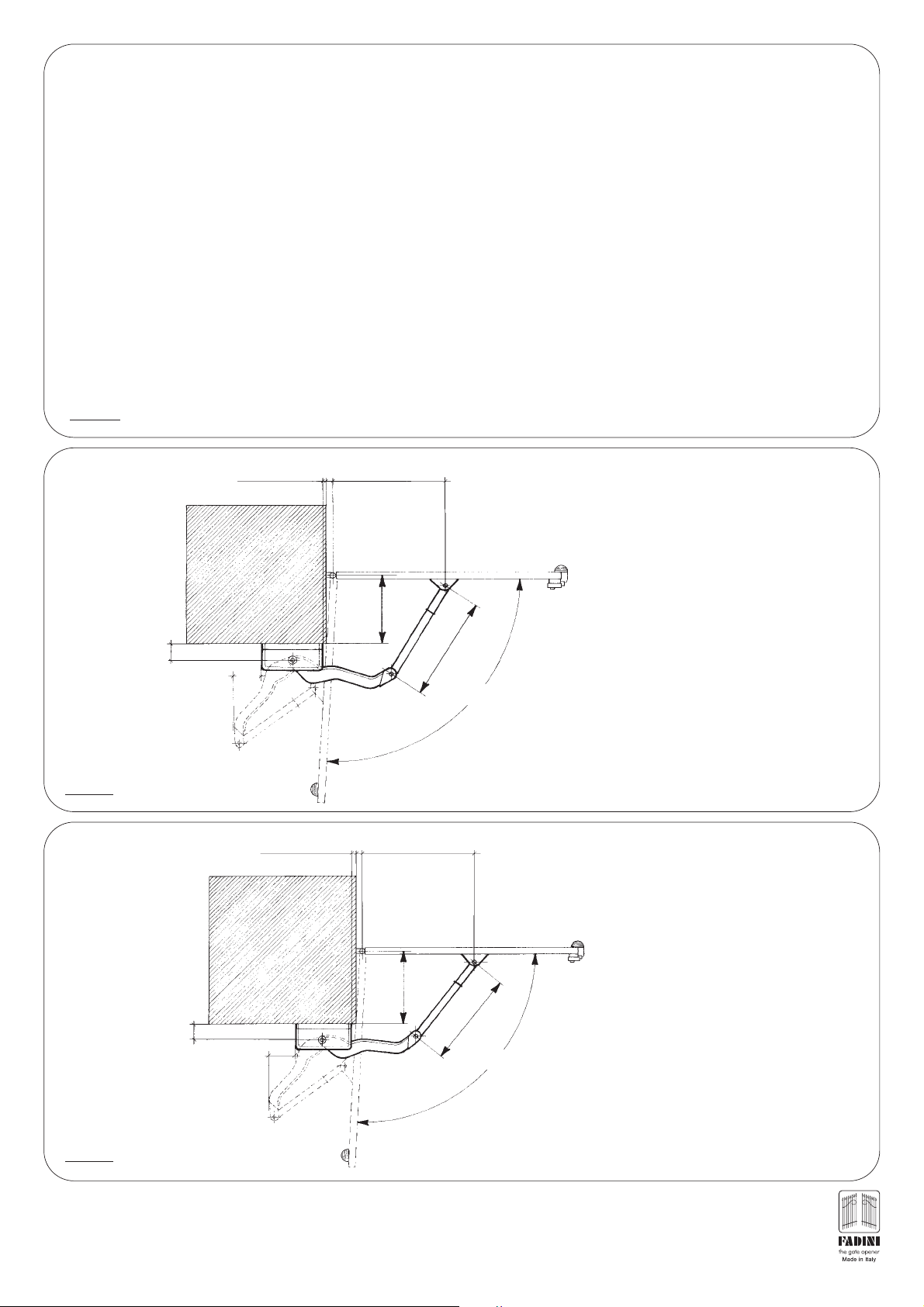
EXAMPLE OF APPLICATIONS TO PILLARS OF VARIOUS DIMENSIONS. DISTANCES ARE NOT BINDING AND
ARE QUOTED FOR REFERENCE ONLY
PIC. 7
20 mm FROM PILLAR
SURFACE LINE
400x400
90
40
GATE STOP
IN OPEN GATE
POSITION
20 mm FROM PILLAR
SURFACE LINE
500x500
40
OPEN GATE LEAF
510
GATE STOP
IN CLOSED
CLOSED GATE LEAF
200
460
100°
POSITION
APPLICATION EXAMPLE
400x400 mm PILLAR
2 m GATE LEAF - 110 Kg
40
250
560
CLOSED GATE LEAF
GATE STOP
IN CLOSED
POSITION
PIC. 8
90
GATE STOP
IN OPEN GATE
POSITION
20 mm FROM PILLAR
SURFACE LINE
600x600
90
60
40
460
APPLICATION EXAMPLE
500x500 mm PILLAR
3 m GATE LEAF - 100 Kg
100°
OPEN GATE LEAF
40
300
560
CLOSED GATE LEAF
460
GATE STOP
IN CLOSED
POSITION
ELECTRIC
LOCK
PIC. 9
6
100°
APPLICATION EXAMPLE
600x600 mm PILLAR
1.8 m GATE LEAF - 140 Kg
GATE STOP
®
IN OPEN GATE
POSITION
OPEN GATE LEAF
Page 7
20 mm FROM PILLAR
SURFACE LINE
700X700
40 580
350
CLOSED GATE LEAF
GATE STOP
IN CLOSED
POSITION
ELECTRIC
LOCK
APPLICATION EXAMPLE
700x700 mm PILLAR
3 m GATE LEAF - 130 Kg
PIC. 10
90
170
OPEN GATE LEAF
40 620
170
800x800
90
GATE STOP
IN OPEN GATE
POSITION
20 mm FROM PILLAR
SURFACE LINE
400
580
100°
CLOSED GATE LEAF
580
GATE STOP
IN CLOSED
POSITION
ELECTRIC
LOCK
APPLICATION EXAMPLE
800x800 mm PILLAR
4 m GATE LEAF - 140 Kg
100°
PIC. 11
PIC. 12
90
900x900
GATE STOP
IN OPEN GATE
POSITION
20 mm FROM PILLAR
SURFACE LINE
GATE STOP
IN OPEN GATE
POSITION
170
OPEN GATE LEAF
40 650
F
ATE LEA
G
PEN
O
450
CLOSED GATE
LEAF
580
100°
GATE STOP
IN CLOSED
POSITION
ELECTRIC
LOCK
APPLICATION EXAMPLE
900x900 mm PILLAR
5 m GATE LEAF - 150 Kg
It is recommended that all gates are provided with adequate gate stops both in open and closed gate positions. When a 5 m
gate is involved the weight must not be greater than 200 Kg and it is required to fit the gate with an electric lock, the operator
must be non locking type. With gates up to 2 m width, it is possible to install the locking type without electric lock.
See the examples and drawings on pages 6 - 7.
®
7
Page 8

GB
13
exp
CONNECTION DIAGRAM FOR SWING GATES
RADIO CONTROL
PLUG-IN CARD SUPPORT
26
27
28
TERMINAL FOR
CONNECTIONS TO
PUSH BUTTONS PULIN 3
DIP-SWITCH
ON
1 2 3 4 5 6 7 8
Should more pairs of photocells be required
than the recommended quantity, fit an auxiliary
transformer outside the control box.
3 4
PULSE TWICE CONSECUTIVELY
TO OPEN BOTH GATE LEAFS
24 V OUTPUT
1
st
CHANNEL
ON
OFF
ON TO “0” THE DELAY
IS OUT OF SERVICE
MICROPROCESSOR
123456
123456789
= PHOTOCELLS 2
Inside photocells N.C. contact
If obstructed they prevent the gates from opening
reverse gate direction during close cycle
N.C. CONTACT
PHOTOCELLS
nd
PAIR =
PEDESTRIAN MODE
ONE PULSE OPENS
ONE GATE LEAF ONLY
COMMON
OPEN SWITCH N.O. CONTACT
TIMER SWITCHES
FUSE
–
7
0
8
9
LEAF DELAY
TIMER CLOSE
+
DWELL TIME
+
MOTOR RUN
+
OPEN & CLOSE TIME
1 AMP. FUSE
24 V OUTPUT
TERMINALS 12-13
CAPACITORS
FLASHING LAMP
630 mA FUSE
FUSE 5 AMPS
630 mA
12,5μF12,5μF
10 11 12 13 14 15 16 17 18
CLOSE SWITCH N.O. CONTACT
STOP SWITCH N.C. CONTACT
RADIO CONTACT N.O.
COMMON
VOLTAGE OUTPUT
ELECTRIC LOCK SUPPLY
24 V INDICATOR - 3 W max.
OUTPUT A.C.
24 V
Max permitted load:
2 pairs photocells
1 radio receiver
7 8
ALL OPERATIONS
OPEN, CLOSE AND
REVERSE
RADIO CONTACT
COMMON
SAFETY CONTACT N.C.
NOTE WELL: For special applications, ie. to switch on lights CCTV etc., SOLID STATE RELAYS are recommended to be used
only. Standard relays would affect the micro-processor.
NOTE WELL: THIS PANEL IS TESTED TO OPERATE GATES ONLY
THROUGH FADINI ACCESSORIES. NO WARRANTY IS
ACKNOWLEDGED BY THE MANUFACTURER IN CASE THAT
OTHER ACCESSORIES ARE USED OR NON CONFORMING
APPLICATIONS ARE MADE WITHOUT THE MANUFACTURER’S
APPROVAL.
19 20 21 22 23 24 25
COMMON
M1 M2
ELECTRIC MOTORS
SINGLE-PHASE
230 V FLASHING LAMP
25 W max.
230 V SINGLE-PHASE
SUPPLY VOLTAGE
LED No. 1 - It switches on when voltage is supplied
26 27 28 3
CONNECTION TO THE “PULIN 3” PUSH
BUTTONS WITH STATUS INDICATION LEDS.
PIC. 13
1234 5678910111213
RADIO CONTACT
CLOSE N.O. CONTACT
OPEN N.O. CONTACT
COMMON
STOP N.C. CONTACT
PIC. 14
345 6
N.O. N.C. N.O.
OPEN STOP
ELECTRICAL CONNECTIONS
KEYSWITCH PRIT 19
STOP
OPEN
CLOSE
COMMON
TERMINAL BOARD
TERMINAL BOARD
1234
PRIT 19
CLOSE
ELECTRICAL WIRING DIAGRAM OF THE ELECTRONIC
PROGRAMMER
Once the connections have been made, do the first switching
test through the control panel. Set the motor run timer so that
the motor is allowed to run 4 - 5 seconds more than the gates.
Set the other timers to meet the site requirements. Set DIP
switch B No. 3 to automatic (ON): on pulsing to 4 - 8 the gates
must be operated as pre-set, ie. opening and only after the
dwell time, closing. Adjust the times through the respective
timers. (See No. 7, 8 and 9 drwg. No. 1643).
With DIP switch “B” No. 3 to semiautomatic (OFF) one pulse
opens the gates, a second pulse to 5 - 9 is needed to close
the gates. Any one pulse to 7 - 8 will open, close or reverse
the gates independently from the operation being performed.
It is recommended to carefully read the instructions in the
control box to have all the functions performed correctly.
The 6 LEDs on the P.C. board indicate the following:
Led No. 1 It switches on when voltage is supplied
Led No. 2 Photocells - Normally on. It switches off when the
photocells are obstructed
Led No. 3 Open - It switches on when the respective switch
is activated
Led No. 4 Close - It switches on when the respective switch
it activated
Led No. 5 Stop - Normally on. It switches off when the
respective switch is activated
Led No. 6 Radio - It switches on whenever a pulse is given,
either from remote control, keyswitch or push
buttons.
®
Drwg. No.
1643
P.C. BOARD
8
Page 9

The below diagram is general for an application of the operator and the complementary accessories which are supplied with the unit.
4
3
2
4x1.5mm
4x1m
2x1mm
2
m
2
230V
±1
50 H
0%
z
1
2
4x1.5mm
2
12
N.W. All the equipment must be properly earthed.
11
10
2x1mm
2x1m
13
5
RG58
4x1.5m
4x1mm
2
2
m
4x1mm
2
6
7
16
2
m
2x1m
2
8
9
2
m
14
2
4x1mm
15
14
17
1) 230V - 50Hz magnetic-thermal differential 0.03 A
circuit breaker (not provided by the manufacturer)
2) Control board
3) Flashing lamp
4) Aerial
Birio A8
5) External radio receiver
6) Surface mount Key-switch
7) Oil-hydraulic operator
8) Photocell projector
Elpro 13 exp
Miri 4
Astro 43/1 R M.Q.B.
Aproli 280 Batt
Polo 44
Prit 19
- Right-hand
9) Electric lock with closed position gate stop
10) Oil-hydraulic operator
11) Photocell receiver
Aproli 280 Batt
Polo 44
- Left-hand
12) Junction box (not provided by the manufacturer)
13) Photocell projector
Polo 44
post mounted
14) Opened position gate stop (not provided)
Polo 44
15) Photocell receiver
16) Digital push button switch
17) Transmitter
Astro 43/2 TR Small
post mounted
Radi 12
PIC. 15
To perform the electrical work, connections are as per diagrams on pages 8-9. Once the connections have been made, adjust the switches
in the control box so that the sequence of operations occurs as pre-set. Set DIP switch 3 on automatic and check if the working times
meet your requirements. On semiautomatic mode, one pulse opens the gates, a second pulse is needed to close the gates.
Sx 2° Dx 1°
PLEASE NOTE: Should the electric
motors fail to start properly because of
power shortage, connect some extra
12.5 μF capacitors to the phase and
common terminals as shown in pic. 16.
COMMON
COMMON M1
PHASE M1
PHASE M1
COMMON M2
PHASE M2
16 17 18 19 20 21 22 23
PHASE M2
Terminal board
Elpro 13
Drwg. No. 1643
exp
PIC. 16
COMMON
12.5 μF
12.5 μF
®
9
Page 10

The two safety pressure valves are identified by colours: “A” open is red; “C” close is green. They are located in the front of the motor/pump
unit, easy to reach for setting operations in order to meet the power requirements Pic. 17.
Once the valves are set, you can fit the cover and the other accessories.
RELEASE BY 1 TURN
TO LET THE AIR OUT
OF OIL RESERVOIR
MORE
POWER
MAXIMUM
PRESSURE VALVE
“CLOSE”
GREEN IN COLOUR
MAXIMUM
PRESSURE VALVE
“OPEN”
RED IN COLOUR
PIC. 17
“C”
“O”
LESS
POWER
“S”
AIR BLEED
THIS STICKER IS FITTED ON
THE OIL RESERVOIR
Via Mantova, 177/A - 37053 Cerea (VR) Italy - Tel. 0442 330422 r.a. - Fax 0442 331054
MOTOR
W
VOLTS
r.p.m.
Nm
Degree of protection IP 555
Working pressure max. 3 MPa (30 Bars)
OIL FADINI
MADE IN ITALY
RELEASE LEVER
“B”
PULL THE LEVER DOWNWARDS TO RELEASE
IMPORTANT
AFTER INSTALLING
APROLI 280 BATT
OIL FADINI
®
s.n.c.
2 PHASE
250
230
1˙350
196.2
HP
A
Hz
μF
RELEASE
BY 1 TURN
“S”
OIL-HYDRAULIC
0.25
1.2
50
12.5
BATT
The setting of the safety pressure valves is to be done so to achieve the exact amount of power required to safely operate the gate. The
more you turn the screw clockwise, the more you increase the power of the operator.
Please note, once APROLI 280 has been fixed, unscrew the air bleed screw by one turn. This screw is fitted on the cap of the oil reservoir,
where the mains cable is led to the motor.
Should the operator “APROLI 280” be removed for maintenance or repairing, tighten the screw “S” to prevent oil from coming out during
handling.
In case of power failure, to open the two leafs fitted with APROLI 280 BATT non-loking type, you have to release the electric lock with
the key and push the gate leafs open by hand in a very smooth way. Should the operator be fitted with the locking device, first pull the
release lever “B” downwards and then push open (Pic. 17). Open the hinged door to have access to the lever.
NEVER CUT THE ELECTRIC CABLES
- Please note that the electric cables must be removed from their terminals by loosening the fastening screws. Never cut the electric
cables. Also make sure that the 230V mains switch No. 3 is off before removing the cables. See page 9, pic. 15.
- Only by keeping to these fitting instructions it can be achieved a reliable installation and the best performance of the operator.
The installation is fully under the responsability of the installation agent, even if it consists entirelly of Fadini products as listed in this
booklet. It is advisable that the system is installed in full compliance with these instructions and in observance of the existing laws
which rule automatic doors.
- All the information, specifications and drawings contained herein are subject to any change that is considered appropriate by the
manufacturer without any previous notice.
®
10
Page 11

APROLI 280 BATT SPECIAL VERSION CODE 287
The flow regulator has the purpose of maintaining
constant the rotation speed of the shaft that operates
the articulated arm.
PIC. 18
FLOW
REGULATOR
OPEN
SPEED
SPEED
SPEED
FLOW
REGULATOR
CLOSE
APROLI 280 BATT TECHNICAL SPECIFICATIONS
FIXING
BRACKET
ELECTRIC MOTOR/
JACK ASSEMBLY
PROTECTION
COVER
139
407
100
190
20x20
260
218
345
570
SPEED
35
190
CONSTANT
SPEED
404
402
290
106
EARTH
240
50
580
520
460
LEFT-HAND ARTICULATED ARM
WITH RETAINING SCREW AND SHOE
RIGHT-HAND ARTICULATED ARM
WITH RETAINING SCREW AND SHOE
580
520
460
PIC. 19
ELECTRIC MOTOR
Power output ...........................................................0.18 KW (0.25 HP)
Supply voltage / Frequency............................................230 V - 50 Hz
Absorbed current ..........................................................................1.2 A
Absorbed power..........................................................................250 W
Capacitor .....................................................................................12.5 μF
Motor rotation speed.........................................................1˙350 r.p.m.
Intermittent service ..........................................................................S 3
PERFORMANCE
Service cycle ..23 sec. Opening - 30 sec. Dwell - 23 sec. Closing - 30 sec. Dwell
Complete cycle time .....................................................................106 s
Complete Opening - Dwell - Closing - Dwell cycles ....No. 34/hour
Annual cycles (with 8 hours of use per day) ..........................99˙000
570
Lh
TURN IT OVER TO
MAKE IT RIGHT-HAND
Rh
HYDRAULIC UNIT
P3 - Hydraulic pump capacity ...........................................0.85 l/min.
Average working pressure .........................................1 MPa (10 bar)
Maximum supplied pump pressure...........................3 MPa (30 bar)
Working temperature ......................................................–20°C +80°C
Opening time ....................................................................................23 s
Rated torque ...........................................................................196.2 Nm
Hydraulic oil type................................................................OIL FADINI
Maximum shaft rotation ................................................................205°
Static weight of operator ............................................................11 Kg
Maximum gate weight ...............................................................100 Kg
Protection standards ..................................................................IP 555
®
11
Page 12

APROLI 280 BATT
WARNINGS
- It is recommended to keep to the instructions here outlined - check the specifications on the motor sticker with your mains
supply.
- Dispose properly of the packaging: cardboard, nylon, polystyrene, through specializing companies.
- Should the operator be removed, do not cut the electric cable. This must be properly removed from the terminal board in the
junction box.
- Switch off the mains switch before removing the junction box cover where the electric cable of APROLI 280 BATT is terminated.
- All the system must be earthed by using the yellow/green wire, marked by its specific symbol.
- It is recommended to read the regulations, suggestions and remarks quoted in the booklet “Safety Norms”.
- Should APROLI 280 BATT be removed for maintenance, servicing or repair, tighten the air bleeding screw (Pic. 17 - Page 10)
to prevent oil coming out of the reservoir during transport.
09-2008
Meccanica Fadini recommends the control panel ELPRO 13 CEI to
achieve an installation that is in conformity to the existing safety
standards as illustrated in our chart.
The electronic programmer ELPRO 13 incorporates and can provide
all the functions which are required by the most demanding
applications with swinging gates.
In addition to the standard features of ELPRO 9 the following
requirements can be provided: “stroke reversing pulse”, pedestrian
mode, stop in any gate position by holding down the remote control
button. Among the added features and improvements of ELPRO 13
in conformity to the European safety standards, there is the mains
rotary switch: it is fitted to the box cover and switches off the mains
voltage whenever the cover is removed.
13
CEI
SINGLE-PHASE
l’apricancello
CUT OFF MAINS SWITCH
The “CE” mark certifies that the operator conforms to the essential
requirements of the European Directive art. 10 EEC 73/23, in relation
to the manufacturer’s declaration for the supplied items, in
compliance with the body of the regulations ISO 9000=UNI EN 29000.
Automation in conformity to EN 12453, EN 12445 safety standards.
CHECKING AND MAINTENANCE:
To achieve an optimum performance and longer life of the
equipment and in observance of the safety regulations, it
is recommended that inspections and proper maintenance
are made by qualified technicians to the whole installation
ie. both the mechanical and electronic parts, as well as
wiring.
- Mechanical parts: maintenance every 6 months approx.
- Electronic apparatus and safety equipment: maintenance
inspection monthly.
EUROPEAN MARK CERTIFYING CONFORMITY TO
THE ESSENTIAL REQUIREMENTS OF THE
STANDARDS 98/37/EC
• DECLARATION OF CONFORMITY
• SAFETY NORMS
• EN 12453, EN 12445 STANDARDS
• CEI EN 60204-1 STANDARDS
• WARRANTY CERTIFICATE ON THE CUSTOMER’S REQUEST
2003/108/CE Directive for
waste electrical and
GB
electronic equipments
DISPOSE OF PROPERLY
ENVIRONMENT-NOXIOUS MATERIALS
®
s.n.c.
AUTOMATIC GATE MANUFACTURERS
Via Mantova, 177/A - 37053 Cerea (Verona) Italy
Tel. +39 0442 330422 r.a. - Fax +39 0442 331054
e-mail: info@fadini.net - www.fadini.net
The growth of MECCANICA FADINI has always been based
on the development of guaranteed products thanks to our
“TOTAL QUALITY CONTROL” system which ensures constant
quality standards, updated knowledge of the European
Standards and compliance with their requirements, in view
of an ever increasing process of improvement.
Distributor’s box
The manufacturers reserve the right to change the products without any previous notice
 Loading...