

Page 1

INSTALLATION MANUAL
GB
®
Page 2
APROLI 280/700 STRONG
INSTRUCTIONS FOR THE INSTALLATION OF THE APROLI 280/700 STRONG SWING
GATE OPERATOR
FOR CORRECT APROLI 280/700 STRONG INSTALLATION AND GOOD PERFORMANCE, PLEASE READ THE INSTRUCTIONS OUTLINED
IN THIS MANUAL CAREFULLY AND KEEP TO THE DIAGRAMS.
IMPORTANT: THE ENTIRE INSTALLATION MUST BE CARRIED OUT BY QUALIFIED TECHNICAL PERSONNEL, WHO ARE ADVISED TO
FOLLOW GOOD INSTALLATION PRACTICE AND KEEP TO CURRENT SAFETY STANDARDS.
GENERAL INFORMATION
- Check that the structure of the gate to be automated is suitable for the application to be installed: make sure that there are no anomalies
in the metal structure, reinforce any weak points and ensure that the leaf hinges are in perfect condition.
- If necessary, reinforce the connection point between the leaf and the bended arm fixing shoe
- The gate’s movement should not be obstructed in any way: excessive rises in the ground, friction in the hinges, ...
- The gate leaves must be installed and levelled on a flat surface
The Aproli 280/700 Strong is an external oil-hydraulic gate operator for swing gates, with two-directional hydraulic locking, suitable
for gates with very large pillars and for heavy gates. It meets all the most demanding installation requirements thanks to the use of a
bended steel arm and “telescopic” end section for leaf fixing.
We recommend using the Aproli 280/700 Strong for leaves of no more than 3.0 metres long and weighing more than 300 kg.
IMPORTANT:
- The Aproli 280/700 Strong should only be installed on gates with leaves up to 3.0 metres long
- An electric lock must always be installed for leaves of over 2.0 metres long.
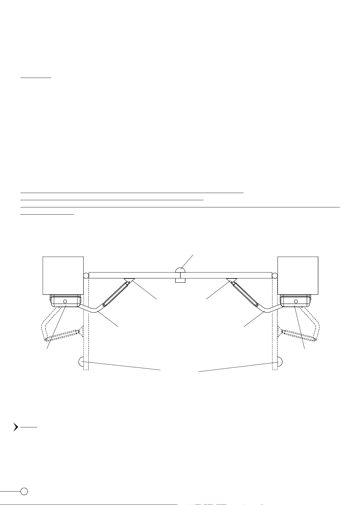
It is advisable to fasten all the open and closed gate stops firmly to the ground, and to check how sturdy they are during the initial gate
operation tests. (Pic.1)
LEFT-HAND
APROLI 280/700
STRONG
GATE STOP IN
CLOSED GATE
POSITION
CLOSED LEAF CLOSED LEAF
PILLAR PILLAR
LEAF FIXING SHOE
LEFT BENDED ARM RIGHT BENDED ARM
OPEN LEAF
GATE STOP IN OPEN
GATE POSITION
PLAN OF GATE WITH TWO APROLI 280/700 STRONG INSTALLED
OPEN LEAF
RIGHT-HAND
APROLI 280/700
STRONG
PIC. 1
2
Page 3
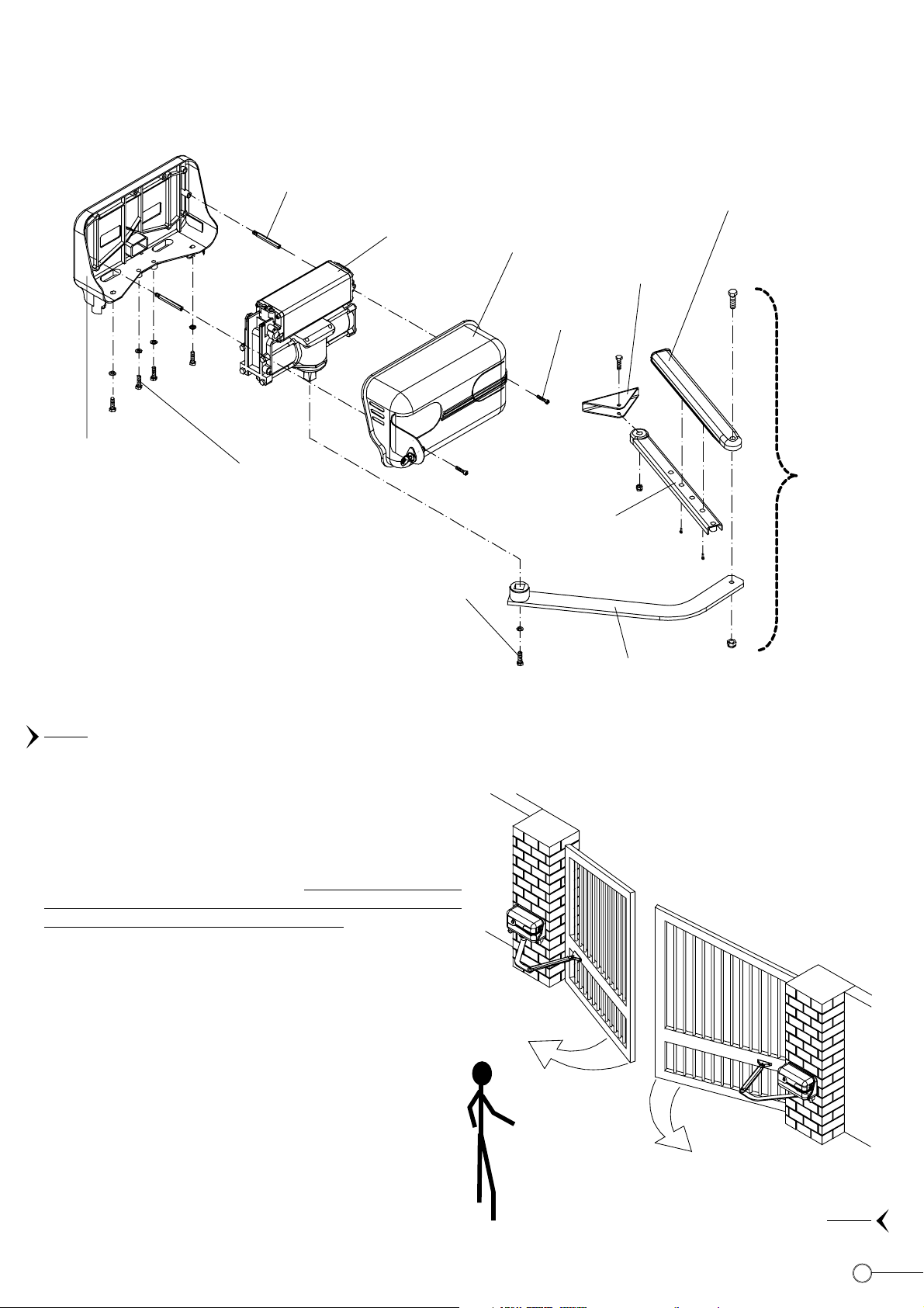
Firstly slide off the whole bended arm by unscrewing the specific screw on the rotation shaft; then remove the protection cover by
unscrewing the 2 fixing screws – A (Pic. 2), one of which is found inside by opening the cover with the customized key. At this point
unscrew the 4 locking screws – B positioned beneath the automation (Pic. 2), thereby making it possible to remove the electric
motor/hydraulic jack assembly, exposing the pillar fixing bracket.
PILLAR FIXING
BASE AND
BRACKET
STUD BOLT
FIXING SCREWS – B
FOR ELECTRIC
MOTOR/HYDRAULIC
JACK ASSEMBLY
LEFT-HAND
ELECTRIC
MOTOR/HYDRAULIC
JACK ASSEMBLY
FIXING SCREWS
FOR ATTACHING
BENDED ARM TO
ROTATION SHAFT
PROTECTION
COVER
COVER FIXING
SCREWS- A
ADJUSTABLE
TELESCOPIC
STRAIGHT
ARM
STRAIGHT ARM
COVER
LEAF FIXING
SHOE
LEFT-HAND
ARTICULATED
ARM
EXPLODED VIEW OF MAIN COMPONENTS OF LEFT-HAND APROLI 280/700 STRONG GATE OPERATOR
PIC. 2
APPLICATION OF TWO APROLI 280/700 STRONG
Before proceeding with the installation and use of the Aproli 280/700
Strong, it is essential to understand the exact position of each operator
in the system. The automations have the abbreviation Sx (left) and
Dx (right) stamped on the hydraulic jack, which can be seen once
the protection cover has been removed:
intended for an observer standing in front of the two gate leaves to
be opened towards the observer himself (Pic. 3).
I.e. if the gate opens inwards the observer will be standing inside
and will see the right-hand Aproli 280/700 Strong on his right; vice
versa, if the gate opens outwards, the observer will be standing
outside and will see the right-hand Aproli 280/700 Strong on his right.
in fact Right and Left are
Lh
LEFT-HAND APROLI 280/700
STRONG
OBSERVER STANDING
IN FRONT – “AGAINST”
THE LEAF OPENING
DIRECTION
ROBUST LEFT-HAND
BENDED ARM
Rh
RIGHT-HAND APROLI
280/700 STRONG
PIC. 3
3
Page 4

SETTING APROLI 280/700 STRONG
In order to install the device, it is firstly necessary to dismantle and expose the individual components; fundamental for both optimal
installation and good performance.
- Swing the lock cover flap placed on the left side of the front protection cover to one side (for both the RH and LH Aproli) and open
the cover with the customized key provided (Pic. 4-A)
- Remove the bended arm by unscrewing the fixing screws positioned on the rotation shaft (for both the RH and LH Aproli) (Pic. 4-B)
- Remove the protection cover by unscrewing the two fixing screws – A on the cover. (Pic. 4-C)
ELECTRIC
MOTOR/HYDRAULIC
JACK ASSEMBLY
COVER FIXING
SCREWS - A
PILLAR FIXING BASE
AND BRACKET
PIC. 4-C
CUSTOMIZED KEY
PIC. 4-A
PROTECTION
LOCK
PROTECTION
COVER
COVER HINGED
DOOR
RIGHT-HAND
BENDED ARM
PROTECTION
COVER
FIXING SCREWS FOR
ATTACHING THE BENDED
ARM TO THE ROTATION
SHAFT
PIC. 4-B
- In order to extract the electric motor/hydraulic jack assembly from the fixing base, unscrew the four fixing screws – B positioned
under the fixing base (Pic. 5)
BENDED ARM AND TELESCOPIC CONNECTION ARM
The straight arm should be bolted to the bended arm. The straight arm offers various different assembly solutions since it has holes
for connection with the telescopic arm cover in 3 different positions (Pic. 6), obtaining a centre distance between the bended arm and
the fixing shoe equivalent to 460 mm, 520 mm or 580 mm. The fixing shoe is attached to a robust gate upright with screws or firmly
welded in place, and is then connected to the adjustable straight arm with one screw.
ELECTRIC MOTOR/
HYDRAULIC JACK
ASSEMBLY
PIC. 5
PILLAR FIXING BASE AND
BRACKET
FIXING SCREWS – B
ELECTRIC MOTOR/
HYDRAULIC JACK ASSEMBLY
LEFT-HAND
BENDED ARM
STRAIGHT
ARM COVER
LEAF FIXING
SHOE
ADJUSTABLE
TELESCOPIC
STRAIGHT
ARM
CENTRE DISTANCE
460 mm, 520 mm, 580 mm
PIC. 6
4
Page 5

FIXTURE TO THE PILLAR
Using a spirit level, fix the fixing base in position with
plugs depending on the type of pillar (Pic. 7) (not provided). When
suitable fixing
PILLAR
deciding the height at which to fix it to the pillar, consider at what
point the articulated arm will be connected to the gate leaf: preferably
on a strong upright. The fixing shoe (Pic. 6) must be bolted or welded
FIXING PLUGS
into position at a distance established after the initial manual leaf
opening and closing tests, following the indicated installation heights
(Pic. 8).
LEVEL
Once the fixing base has been installed, insert and fix the electric
motor/hydraulic jack assembly into position using the 4 fixing screws
– B (Pic. 5).
The following table indicates some installation distances. These are
not obligatory and are for reference purposes only (Pic. 8).
The distances indicated must be used to obtain an automation that
is able to close the leaf decisively.
FIXING BASE
AND BRACKET
POWER CABLE ALREADY
INSERTED INSIDE A TUBE
PREPARED BEFORE
INSTALLATION INSIDE THE
PILLAR
Pillar dimensions A (mm) B (mm) C (mm) D (mm) G° Gate leaf
400 x 400 (mm) 510 200 460 50 100° 2,0 m
500 x 500 (mm) 560 250 460 60 100° 3,0 m
600 x 600 (mm) 560 300 460 / 95° 1,80 m
700 x 700 (mm) 580 350 580 140 95° 3,0 m
800 x 800 (mm) 620 400 580 135 90° 4,0 m
900 x 900 (mm) 650 450 580 50 90° 5,0 m
PIC. 7
PILLAR
20 mm from the pillar edge
110
D
GATE STOP IN
OPEN GATE
POSITION
40
B
OPEN LEAF
GATE STOP IN
A
CLOSED LEAF
C
G°
CLOSED GATE
POSITION
PIC. 8
5
Page 6

ELECTRICAL CONNECTIONS TO THE ELPRO 13 CEI PROGRAMMER
Before making any connections, study the enclosed electrical diagrams carefully.
IMPORTANT: The whole electrical system must be earthed (Pic. 9); DO NOT CUT the electric cable for installation requirements; CUT
OFF the 230 V power supply (line switch not connected. (Pic. 9), during the electric wiring installation and connection phase.
- Power supply, electric motor and flashing light connections are made with electric cables with a section of 1.5 mm2 for a maximum
distance of 50 m. For distances of over 50 metres, we recommend using electric cables with a section of 2 mm2.
- For limit switches, photocells, pushbuttons and accessories use cables with 1 mm2 wires (Pic. 9)
IMPORTANT: PERFORM A RISK ANALYSIS IN COMPLIANCE WITH EN 12445 AND EN 12453 STANDARDS AND INSTALL THE NECESSARY
SAFETY DEVICES. THE FOLLOWING FIGURE PROVIDES AN INDICATION OF THE ESSENTIAL ACCESSORIES FOR THE SYSTEM OPERATION.
THE SYSTEM SHOULD BE CUSTOMIZED AT THE INSTALLER AND USER’S DISCRETION DEPENDING ON THE VARIOUS REQUIREMENTS
AND CHARACTERISTICS OF THE ENVIRONMENT.
14
1
13
2
12
3
4
5
6
8
7
1) “ELPRO 13 CEI” PROGRAMMER WITH PLUG-IN JUBI 433 RADIO RECEIVER
2) 0.03 A MAGNETO-THERMAL DIFFERENTIAL SWITCH
3) JUNCTION BOX
4) LEFT-HAND APROLI 280/700 STRONG
5) PHOTOCELL TRANSMITTER POLO 44 ON POST
6) GATE STOP IN OPEN GATE POSITION
7) JUBI SMALL 433 TRANSMITTER
8) ELECTRIC LOCK
9) PHOTOCELL RECEIVER POLO 44 ON POST
10) RIGHT-HAND APROLI 280/700 STRONG
11) ENCODED KEYSWITCH PRIT 19
12) MIRI 4 FLASHING LIGHT FITTED WITH BIRIO ANTENNA
13) PHOTOCELL TRANSMITTER POLO 44
14) PHOTOCELL RECEIVER POLO 44
11
9
LEFT-HAND APROLI ELECTRIC
MOTOR TERMINAL BOX
10
6
PIC. 9
6
Page 7

Once all the electrical connections have been made, carry out the initial operation tests, adjust the motor run timer 09 for a period of
4-5 seconds more than the real gate opening time; the dwell timer 08, and the leaf closure delay 07 (Pic. 10)
In order to set automatic or semiautomatic operation, flick the Dip-switch B:
- Automatic Operation: with dip-switch lever No. 3 in the ON position, once the opening pulse has been given (contact 4 and 8 on the
Elpro 13 CEI programmer terminal box), the gate opens and dwells for the time set by the potentiometer 08, then closes automatically.
- Semiautomatic Operation: with dip-switch lever No. 3 in the OFF position, once the opening pulse has been given, the gate opens,
while a closing pulse must be given in order to close in (contact 5 and 8 on the Elpro 13 CEI programmer terminal box).
- Radio Contact: contact 7 and 8 on the Elpro 13 CEI electronic programmer terminal box (Pic. 10), the automation reverses the movement
that it is carrying out upon every pulse from the keyswitch, the transmitter or the wall push buttons (it is advisable to read the instructions
leaflet enclosed with the electronic programmer carefully).
WARNING: If the electric motors have insufficient drive power due to shortage of electric current, add two 12 µF capacitors (one for
each electric motor), connecting them in parallel to the individual electric motor phases.
13
CEI
FOR SWING GATES - SINGLE-PHASE
RADIO CONTROL
PLUG-IN CARD SUPPORT
1° CHANNEL
26
27
28
TERMINALS FOR THE
CONNECTION OF THE
PUSH BUTTONS PULIN 3
DIP-SWITCH
ON
B
12 435678
Should more pairs of photocells be required
than the recommended quantity, fit an
auxiliary transformer outside the control box.
ON
OFF
PEDESTRIAN MODE
ONE PULSE OPENS
ONE GATE LEAF ONLY
34
PULSE TWICE
CONSECUTIVELY TO OPEN
BOTH GATE LEAFS
24 V OUTPUT
MICROPROCESSOR
1234 5 6
PAIR-
nd
-PHOTOCELLS 2
INSIDE PHOTOCELLS N.C. contact. If
obstructed, they prevent the gates from
PHOTOCELLS
N.C. CONTACT.
opening, reverse gate direction during
close cycle.
ON TO “0” THE DELAY
IS OUT OF SERVICE
FADINI
43211312111098765
COMMON
OPEN SWITCH N.O. CONTACT
CLOSE SWITCH N.O. CONTACT
78
ALL OPERATIONS
OPEN, CLOSE & REVERSE
RADIO CONTACT
STOP SWITCH N.C. CONTACT
COMMON
RADIO CONTACT N.O.
7
8
9
VOLTAGE OUTPUT
ELECTRIC LOCK SUPPLY
0
24 Vac OUTPUT
24 V - 3 W max. INDICATOR
2 pairs photocells
Max. permitted load:
LEAF DELAY
TIMER
+
CLOSE
DWELL TIME
+
MOTOR RUN
TIME OPEN
+
& CLOSE
F5
1 Amp. FUSE:
24 V OUTPUT
TERMINALS 12 - 13
CAPACITORS
CUT OFF SWITCH
BY COVER KNOB
12,5 µF 12,5 µF
16 252423222120191817
COMMON
LED 1: LIGHTS UP WHEN THE CARD IS POWERED
1 radio receiver
LED 2: SWITCHES OFF WHEN THERE IS AN OBSTACLE IN FRONT
LED 3: OPEN. LIGHTS UP UPON OPENING PULSE
LED 4: CLOSE. LIGHTS UP UPON CLOSE PULSE
LED 5: STOP, SWITCHES OFF UPON STOP PULSE
LED 6: RADIO, LIGHTS UP UPON EVERY RADIO PULSE
N. W.: for special applications, ie. to switch on lights - CCTV etc…, SOLID
STATE RELAYS are recommended to be used only.
Standard relays would affect the micro-processor.
N.W.: THIS PANEL IS TESTED TO OPERATE GATES ONLY THROUGH FADINI
ACCESSORIES. NO GUARANTEE FOR ACCESSORIES OF OTHER MAKE OR
SPECIAL APPLICATIONS.
COMMON
M1
ELECTRIC MOTORS
SINGLE-PHASE
OF THE PHOTOCELLS
M2
230 V SINGLE-PHASE
SUPPLY VOLTAGE
230 V - 25 W max
FLASHING LAMP
F3 F1
630 mA
FUSE
FLASHING
LAMP
F4
630 mA
FUSE
F2
5 Amp.
FUSE
5 Amp.
FUSE
Drwg. No. 2014
7
Page 8

FEATURES OF THE ELECTRONIC PROGRAMMER ELPRO 13 CEI FOR
SWINGING GATES
All the electrical connections are to be made as per the following instructions and diagrams. Supply the terminals 24-25 with 230V 50 Hz single phase voltage. The “red LED” switches on and stays on as long as the board is properly supplied. Through the timer No. 9
you can control the running time of the motor in both cycles, OPEN and CLOSE.
Set it so that the running time of the motor is longer than the actual travel of the gate: set the timer No. 8 -DWELL- ie. the interval between
open and re-closing, so that you can meet the required interval of time. The timer No. 7 -LEAF DELAY in “close” cycle- is to be set as
follows: on to “–” (less) the delay is out of service; clockwise on to “+” (more) the delay is operative.
- With the electric motor connected to terminals 19 - 20 - 21: the delay is operative in the “open” cycle, with a factory pre-set time.
- With the electric motor connected to terminals 16 - 17 - 18: the delay is operative in “close” cycle and can be adjusted through the
timer No. 7 on to “less” or “more”.
LOGIC OF THE ELECTRONIC PROGRAMMER: When a pulse is given, the flashing light switches on. After three seconds the motors start.
During the interval before re-closing, the light stays on. When the gates are fully re-closed, the light keeps on flashing for three more
seconds and then switches off automatically.
The 3 second interval (pre-flashing) which precedes the actual start of the motors can be eliminated by means of the DIP-SWITCH “B” No.4.
LED No. 1: It switches on when voltage is supplied.
LED No. 2: “PHOTOCELLS”. Normally on. It switches off when the photocells are obstructed.
LED No. 3: “OPEN”. It switches on when the respective switch is activated.
LED No. 4: “CLOSE”. It switches on when the respective switch is activated.
LED No. 5: “STOP”. Normally on. It switches off when the respective switch is activated.
LED No. 6: “RADIO”. It switches on whenever a pulse is given, either from remote control, keyswitch or push buttons.
DIP-SWITCH B SETTING IN ELPRO 13 CEI
N° 1 OFF = PHOTOCELLS. NO STOP IN OPEN CYCLE. REVERSE/CLOSE
N° 2 OFF = REMOTE CONTROL. REVERSE
N° 3 OFF = NO AUTOMATIC RECLOSING
N° 4 OFF = NO PRE-FLASHING
N° 5 OFF = REMOTE CONTROL. NO STOP AND HOLD AS LONG
AS BUTTON DOWN. IT OPENS STRAIGHT AWAY
N° 6 OFF = BOTH LEAFS ARE OPERATED
N° 7 OFF = S. R. P. OUT OF SERVICE
N° 8 OFF = LEAF DELAY OPEN CYCLE.
ONE STARTS BEFORE THE OTHER
N° 1 ON = STOP DURING OPEN CYCLE
N° 2 ON = NO REVERSE DURING OPEN CYCLE
N° 3 ON = AUTOMATIC RECLOSING
N° 4 ON = PRE-FLASHING
N° 5 ON = STOP AND HOLD AS LONG AS
THE BUTTON IS KEPT DOWN
N° 6 ON = PEDESTRIAN. ONE LEAF ONLY
GATES IN CLOSE POSITION
N° 7 ON = S. R. P. IN SERVICE
GATES IN CLOSE POSITION
N° 8 ON = NO LEAF DELAY
BOTH MOTORS START TOGETHER
LAMP ON = GATE OPEN
LAMP FLASHES SLOWLY = GATE OPENING
LAMP FLASHES FAST = GATE CLOSING
LAMP OFF = GATE CLOSED
1) It is advisable not to expose the control box directly to weather conditions; if mounted outside, a suitable enclosure is recommended
to protect it from sunshine and rain.
2) Bridge terminals 1 - 2 if you do not require any photocells.
3) Should two sets of photocells be required, these are to be series connected to terminals 1 - 2, contact normally closed.
4) Bridge terminals 6 - 8 if you do not require any keyswitch or push buttons.
5) Fit the mains to the control box with a high sensitivity, differential, magnetic-thermal switch, 0.03 Amps.
6) OPERATING MODE WITH TWO PAIRS OF PHOTOCELLS, INDEPENDENT FROM EACH OTHER
Dip-switch No. 1 set to OFF, connect the pair of photocells that are inside the property to the terminals marked “2
The second pair always stops the gate in open cycle in case of an obstacle.
During close cycle the second pair reverses the gate direction.
7) NOTE WELL
FAULT FINDING:
- Check supply voltage with a tester: it must be 230 V, single-phase.
- Check the high voltage fuses.
- Check the low voltage fuses.
- Check if the photocell contacts are normally closed.
- Check voltage from the control box to the electric motor(s): power might have dropped.
- The section of the electric cables to the motor(s) must not be less than 1.5 mm
- Connect the other pair to the terminals 1 - 2
This pair performs in the standard pre-set mode, ie:
no stop during open cycle, REVERSING GATE DIRECTION DURING CLOSE CYCLE.
Terminals to stay linked out should the second pair of photocells not be used, and set the desired operating mode through Dip-switch No. 1.
* 24 V ~ output. Terminals 12 - 13. It can supply power for 2 pairs of photocells plus 1 radio receiver.
Terminal 11 provides a power output for a lamp. 24 V - 3 W max.
Flashing lamp output. Terminals 22 - 23. Maximun available power 25 W max.
8
2
.
nd
pair”.
Page 9

FEATURES AND TECHNICAL SPECIFICATIONS
“Elpro 13 CEI” represents the latest state of the art technology for control panels. It is extremely versatile and can meet the most various
requirements. It is fitted with the “Cut Off Switch” by cover knob.
It has the same functions as “Elpro 9” and incorporates additional advantages as follows: Stroke Reversing Pulse, Pedestrian Operating
Mode (where one leaf only can be operated allowing people to walk in/out), STOP and HOLD function by keeping the remote control
button pressed down. Further improvements can be noted in the “Elpro 13 CEI”:
- Addition of a 1 Amp. fuse to the 24 V circuit as a protection for the accessories (remote control - photocells -etc.) which are connected
to the terminals 12 - 13 and for the panel itself in that it can prevent short circuit during installation.
- The pulse to the electric lock is increased to 2 seconds. Releasing is so much easier as the electric lock is released with an anticipation
of 100 msec. before the gate starts moving.
- A 24 V - 3 W lamp indicates gate operations (Gate CLOSED = Lamp OFF - Gate in OPEN cycle = Lamp flashes slowly - Gate OPEN =
Lamp stays ON without flashing - Gate in CLOSE cycle = Lamp flashes fast).
- It provides a better switching intelligence design to enhance the reliability of the relays.
- The Motor Run Time is independent from the Leaf Delay Time in close cycle (the delay time is automatically added to the duration of
the -opening time).
- The 8 Dip-switches can be arranged into any of the possible patterns to achieve the required operating modes without any risk of
interference with one another.
“STROKE REVERSING PULSE” and “S.1A.P.”
Set Dip-switch No. 7 to ON The ”Stroke Reversing Pulse” (S.R.P.) is activated only with the gate in the CLOSE position. The pulse operates
the gate in the CLOSE direction first and then immediately reverses into OPEN (This will help the gate lock to release). All the other
operations will be performed in the standard way. No danger comes from the Stroke Reversing Pulse. This function remains in service
with the panel set to “Pedestrian Mode”. Set Dip-switch No. 6 to ON for “Pedestrian Mode” (S.1A.P.), terminals 3 - 4. Only one leaf is
operated when the OPEN button is pressed down. Automatic reclosing. If the OPEN button is pressed twice in a row, both leafs are
opened. The S.1A.P. function is activated only when the gate is in the fully CLOSE position. The remote control always operates both
gates, terminals 7 - 8.
The box of ELPRO 13 CEI and its cover are made of weather-proof, shock-resistant plastic material which has a degree of protection
equalling IP 437. The cover is fitted with a knob of quick response in case of an emergency by cutting off the voltage supply.
MANUAL RELEASE
The Aproli 280/700 Strong manual release makes it possible to move the gate manually, in the case of a power failure or during the initial
manual opening and closing tests. The manual release lever – S can be accessed by opening the protection cover with the customized
key. Lower the lever in order to release the gate (Pic. 11).
PROTECTION
COVER
MANUAL RELEASE
LEVER – S INSIDE
LOWER THE
MANUAL RELEASE
LEVER – S TO
RELEASE
PIC. 11
MANUAL RELEASE
LEVER - S
9
Page 10

ADJUSTING THE LEAF DRIVE FORCE
During the initial manoeuvre operations it will be necessary to calibrate the opening and closing drive force that each individual Aproli
280/700 Strong exercises on the leaves; it is therefore necessary to remove the protection cover (Pic. 12), firstly using the customized
key on the cover, thereby exposing the automation and the individual pressure regulators that can be adjusted using a flat screwdriver.
NOTE: during factory production, the two hydraulic pressure regulators on each individual Aproli 280/700 Strong are distinguished by
different colours: on the Right Aproli and the Left Aproli, the red regulator adjusts the drive force of the leaf during closing, while the
green regulator adjusts the drive force of the leaf during opening (Pic.12)
LEFT-HAND APROLI 280/700 STRONG RIGHT-HAND APROLI 280/700 STRONG
DRIVE FORCE
ADJUSTMENT
VALVES
LEFT-HAND APROLI 280/700 STRONG
RED REGULATOR = DRIVE
DURING CLOSING
GREEN REGULATOR =
DRIVE DURING OPENING
PROTECTION
COVER
COVER FIXING
SCREWS - A
DRIVE FORCE
ADJUSTMENT
VALVES
RIGHT-HAND APROLI 280/700 STRONG
GREEN REGULATOR =
DRIVE DURING OPENING
RED REGULATOR =
DRIVE DURING
CLOSING
PIC. 12
10
MANUAL RELEASE
LEVER – S
CLOCKWISE=
MORE DRIVE
FORCE
ANTICLOCKWISE=
LESS DRIVE FORCE
MANUAL RELEASE
LEVER – S
Page 11

TECHNICAL DATA
ELECTRIC MOTOR
Power output...........................................................0.18 KW (0.25 HP)
Supply voltage / Frequency....................................230 V c.a. / 50 Hz
Absorbed current........................................................................250 W
Absorbed power............................................................................1.2 A
Capacitor........................................................................................12 µF
Motor rotation speed ...........................................................1˙350 rpm
Intermittent service...........................................................................S3
SERVICE
Duty cycle......................... 23 s Opening - 30 s Dwell - 23 s Closing
Time of one complete cycle..........................................................76 s
No. of complete cycles: Open - Dwell - Close ........47 cycles/hour
No. of cycles a year, 8 hours a day........................................137˙000
OVERALL DIMENSIONS
OIL-HYDRAULIC PUMP
Pump flow rate - P3 ............................................................0.85 l /min.
Average working pressure.......................................1 MPa (10 bars)
Max. pump pressure .................................................3 MPa (30 bars)
Working temperature.....................................................–20°C +80°C
Hydraulic oil................................................OIL A 15 FADINI by AGIP
Static weight of operator with arm ...........................................20 Kg
Opening time....................................................................................23 s
Rated torque..............................................................................137 Nm
260
400
105
190
240
580
10
SX
570
520
460
150
345
150
220
580
30
520
460
407
570
DX
140
10
50
52
52
50
11
Page 12

CHECKING AND MAINTENANCE:
To achieve an optimum performance and longer life of the equipment and in observance of the safety regulations, it is recommended
that inspetions and proper maintenance are made by qualified technicians to the whole installation ie. both the mechanical and
electronic parts, as well as wiring.
- Mechanical parts: maintenance every 6 months approx.
- Electronic apparatus and safety equipment: maintenance every month.
Lineagrafica
12-2003
The “CE” mark certifies that the operator conforms to the essential
requirements of the European Directive art. 10 EEC 73/23, in relation
to the manufacturer’s declaration for the supplied items, in
compliance with the body of the regulations ISO 9000-UNI EN 29000.
Automation in conformity to EN 12453, EN 12445 safety standards.
EUROPEAN MARK CERTIFYING CONFORMITY TO
THE ESSENTIAL REQUIREMENTS OF THE
STANDARDS 98/37/EC
• DECLARATION OF CONFORMITY
• GENERAL WARNINGS
• EN 12453, EN 12445 STANDARDS
• CEI EN 60204-1 STANDARDS
• WARRANTY CERTIFICATE ON THE CUSTOMER'S REQUEST
®
s.n.c.
AUTOMATIC GATE MANUFACTURERS
The growth of MECCANICA FADINI has always been based
on the development of guaranteed products thanks to our
“TOTAL QUALITY CONTROL” system which ensures
constant quality standards, updated knowledge of the
European Standards and compliance with their
requirements, in view of an ever increasing process of
improvement.
®
the gate opener
Made in Italy
Distributor’s box
The manufacturers reserve the right to change the products without any previous notice
Via Mantova, 177/A - 37053 Cerea (Verona) Italy - Tel. 0442 330422 r.a. - Fax 0442 331054 - e-mail: info@fadini.net - www.fadini.net
 Loading...