

Page 1
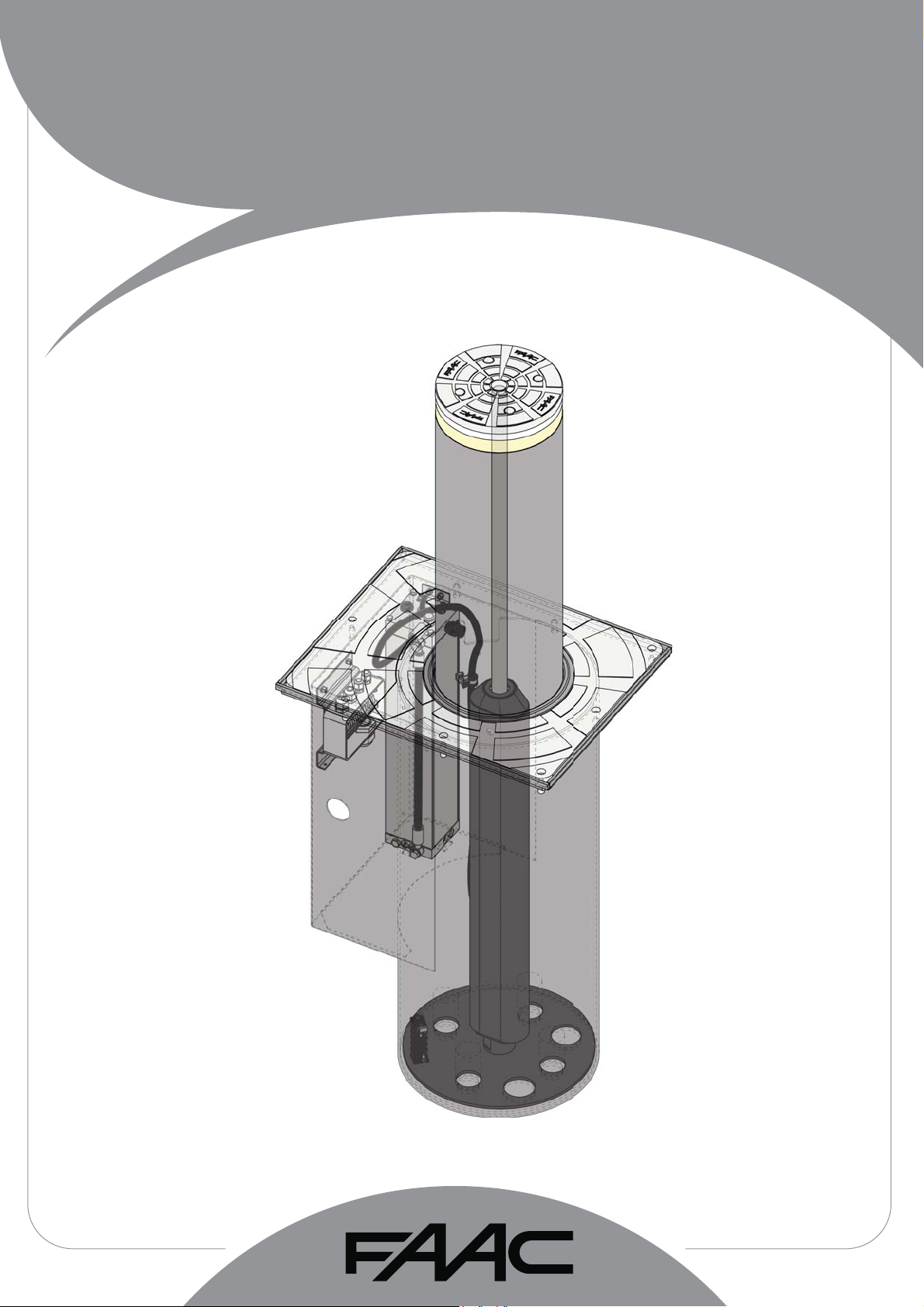
J200 HA
J200 HA
Page 2
CE DECLARATION OF CONFORMITY FOR MACHINES
(DIRECTIVE 2006/42/EC)
Manufacturer: FAAC S.p.A.
Address: Via Calari, 10 - 40069 Zola Predosa BOLOGNA - ITALY
Declares that: the operator mod. J200 HA
is built to be integrated into a machine or to be assembled with other machinery to create a machine under the
provisions of Directive 2006/42/EC;
conforms to the essential safety requirements of the following EEC directives:
2006/95/EC Low Voltage Directive
2004/108/EC Electromagnetic Compatibility Directive
and also declares that it is prohibited to put into service the machinery until the machine in which it will be integrated
or of which it will become a component has been identifi ed and declared as conforming to the conditions of
Directive 2006/42/EEC and subsequent amendments.
Bologna, 01st September 2012
The Managing Director
A. Marcellan
CE DECLARATION OF CONFORMITY FOR MACHINES
Manufacturer: FAAC S.p.A.
Address: Via Calari, 10 - 40069 Zola Predosa BOLOGNA - ITALY
Declares that: the control unit 624BLD
ENGLISH
• conforms to the essential safety requirements of the following EEC directives:
2006/95/EC Low Voltage Directive
2004/108/EC Electromagnetic Compatibility Directive
Additional note:
This product underwent tests in a typical homogenous confi guration
(all products manufactured by FAAC S.p.A.).
Bologna, 01st September 2012
The Managing Director
A. Marcellan
1
Page 3

WARNINGS FOR THE INSTALLER
GENERAL SAFETY OBLIGATIONS
1. A TTENTION! T o ensure the safety of people, it is important that you read all
the following instructions. Incorrect installation or incorrect use of the
product could cause serious harm to people.
2. Carefully read the instructions before beginning to install the product.
3. Do not leave packing materials (plastic, polystyrene, etc.) within reach of children
as such materials are potential sources of danger.
4. Store these instructions for future reference.
5. This product was designed and built strictly for the use indicated in this
documentation. Any other use, not expressly indicated here, could
compromise the good condition/operation of the product and/or be a source
of danger.
6. FAAC declines all liability caused by improper use or use other than that for which
the automated system was intended.
7. Do not install the equipment in an explosive atmosphere: the presence of
inflammable gas or fumes is a serious danger to safety.
8. For non-EU countries, to obtain an adequate level of safety, the Standards
mentioned above must be observed, in addition to national legal regulations.
ENGLISH
9. FAAC is not responsible for failure to observe Good Technique in the construction
of the closing elements to be motorised, or for any deformation that may
occur during use.
10. Installation must be performed in compliance with current Standards.
11. Before attempting any job on the system, cut out electrical power.
12. The mains power supply of the automated system must be fitted with an all-pole
switch with contact opening distance of 3 mm or greater. Use of a 6A thermal
breaker with all-pole circuit break is recommended.
13. Make sure that a differential switch with threshold of 0.03 A is fitted upstream of
the system.
14. Make sure that the earthing system is perfectly constructed and connect metal
parts of the closure to it.
15. The automated system is supplied with an intrinsic anti-crushing safety device
consisting of a torque control. Nevertheless, its tripping threshold must be
checked as specified in the Standards indicated at point 10.
16. The safety devices (EN 12978 standard) protect any danger areas against
mechanical movement Risks, such as crushing, dragging, and shearing.
17. Use of at least one indicator-light (i.e. flashing lamp incorporated in the bollard
head) is recommended for every system, as well as a warning sign adequately
secured to the frame structure, in addition to the devices mentioned at point
“16”.
18. FAAC declines all liability as concerns safety and efficient operation of the
automated system, if system components not produced by FAAC are used.
19. For maintenance, strictly use original parts by FAAC.
20. Do not in any way modify the components of the automated system.
21. The installer shall supply the user with the necessary information for the manual
operation of the system in the event of emergency
22. Do not allow children or adults to stay near the product while it is operating.
23. Keep remote controls or other pulse generators away from children, to prevent the
automated system from being activated involuntarily.
24. Transit on the bollard is permitted only when the device is completely down.
25. The user must not attempt any kind of repair or direct action whatever and contact
qualified personnel only.
26. Anything not expressly specified in these instructions is not permitted.
INDEX
1 GENERAL NOTES ......................................................................................................................................... 3
2 DESCRIPTION AND TECHNICAL SPECIFICATIONS................................................................................... 3
3 DIMENSIONS .................................................................................................................................................. 4
4 FACILITIES ..................................................................................................................................................... 4
5 ELECTRIC WIRING ........................................................................................................................................ 6
6 MANUAL OPERATION ................................................................................................................................... 9
7 AUTOMATIC OPERATION ............................................................................................................................. 9
8 MAINTENANCE .............................................................................................................................................. 9
9 ELECTRICAL CONNECTIONS .................................................................................................................... 10
10 PRE-SETTING SELECTION ..........................................................................................................................11
11 POSITIONING THE LOOPS ..........................................................................................................................11
12 CONNECTING MORE BOLLARDS ............................................................................................................. 12
12.1 CONNECTION OF UP TO 4 BOLLARDS ON A SINGLE BOARD .................................................................... 12
12.2 CONNECTION OF UP TO 8 BOLLARDS ON TWO 624BLD MASTER – SLAVE CONNECTION .................12
12.3 WIRING OF UP TO 4 BOLLARDS ON A SINGLE BOARD ..............................................................................13
12.4 WIRING OF UP TO 8 BOLLARDS ON TWO 624BLD IN MASTER – SLAVE CONNECTION .......................14
13 TROUBLESHOOTING .................................................................................................................................. 15
14 CLEANING / UNMOUNTING PROCEDURE ................................................................................................ 15
2
Page 4
J200 HA BOLLARD
Please read with the utmost care this manual supplied with the product, since it contains important indications
about safety, installation, use and maintenance.
1 GENERAL NOTES
J200HA is an automatic hydraulic traffic bollard. The cylinder is moved by an hydraulic unit located inside the cylinder. The hydraulic
release occurs by direct action on the hydraulic unit. As an alternative, if the optional solenoid valve is present, the release occurs
automatically in the event of a power cut.
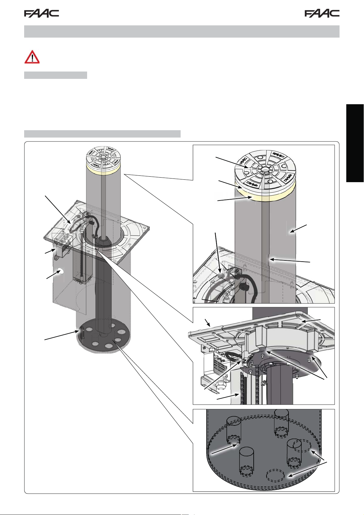
2 DESCRIPTION AND TECHNICAL SPECIFICATIONS
ENGLISH
1. Hydraulic unit
2. Junction box
3. Cable routing hole
4. Magnetic contact, down (NC polarity)
5. Crown
6. LED flashing lamp
7. Reflective stripe
8. Oil filler plug
9. Piston
10. Cylinder
11. Magnetic contact, up (NC polarity)
12. Cable routing chain
13. Upper plate (bollard)
14. Upper plate (Hydraulic unit)
15. 4 stop points, up
16. stoppers, down
17. Water drainage holes
Fig. 1
3
Page 5
Tab. A - Technical Specifi cations
MODEL J200
Power supply 230 V~ 50 Hz
Max. absorbed power (W) 220
Max. force (N) 1800
Max. pump delivery (lpm)
Minimum lifting time (sec) 7
Minimum lowering time (sec) 7
ENGLISH
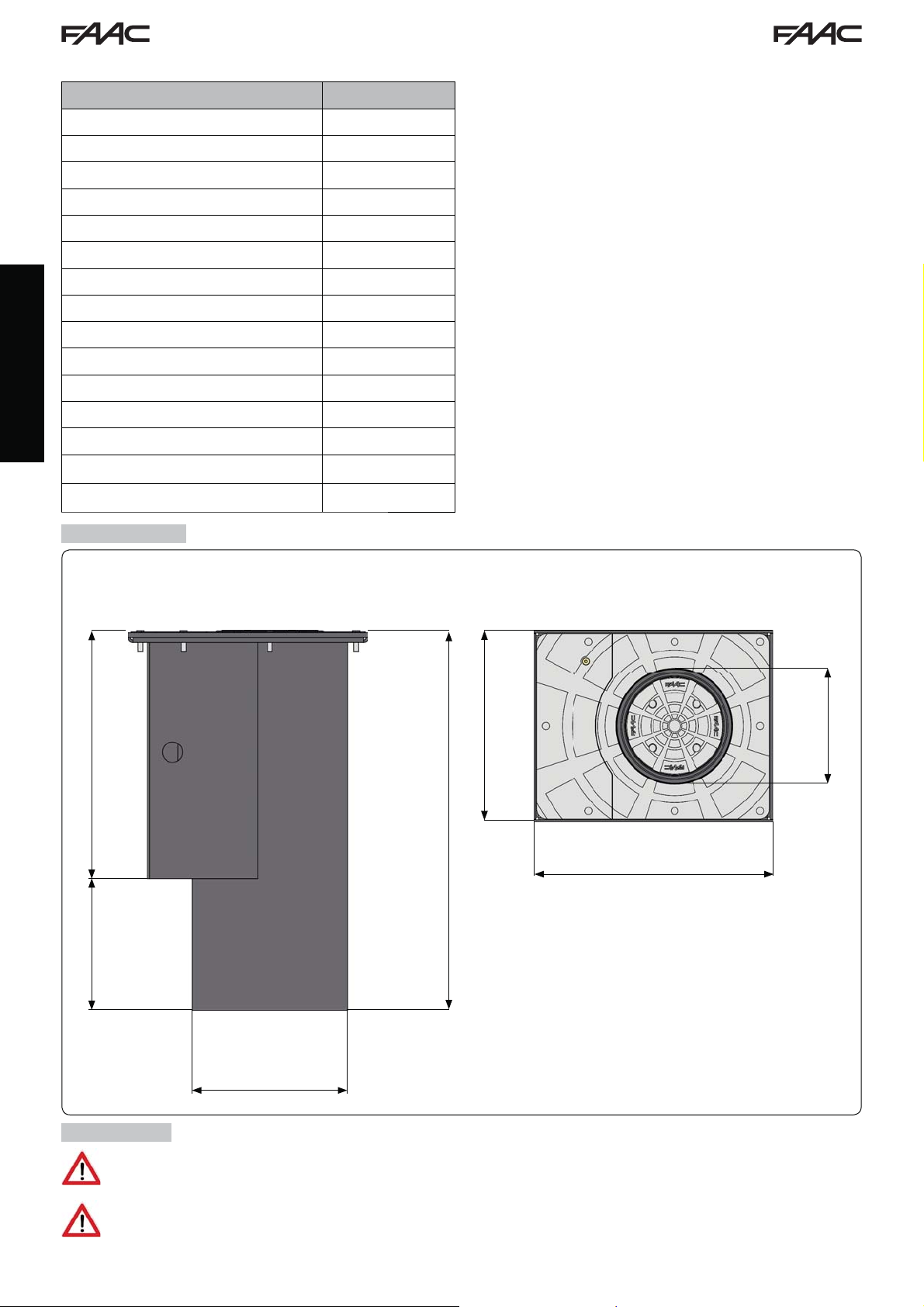
3 DIMENSIONS
Dimensions in mm
3
Use temperature (°C) -15 +55
Weight (Kg) 100
Oil quantity (l) 2,6
Protection class IP56
Overall dimensions See Fig.2
Capacitor
Use frequency Semi-Intensive use
R.O.T. at 55°C (min) 40
R.O.T. at 23°C (min) 100
(3) 16μF - 400V
400
790
500
275 515
322
4 FACILITIES
Make sure that the place where the bollard is to be installed is not a cavity; if this is the case, partially protect
the bollard with a drainage channel equipped with covering grid.
200
Fig. 2
Dig up to a depth of about 1.1 m
4
Page 6
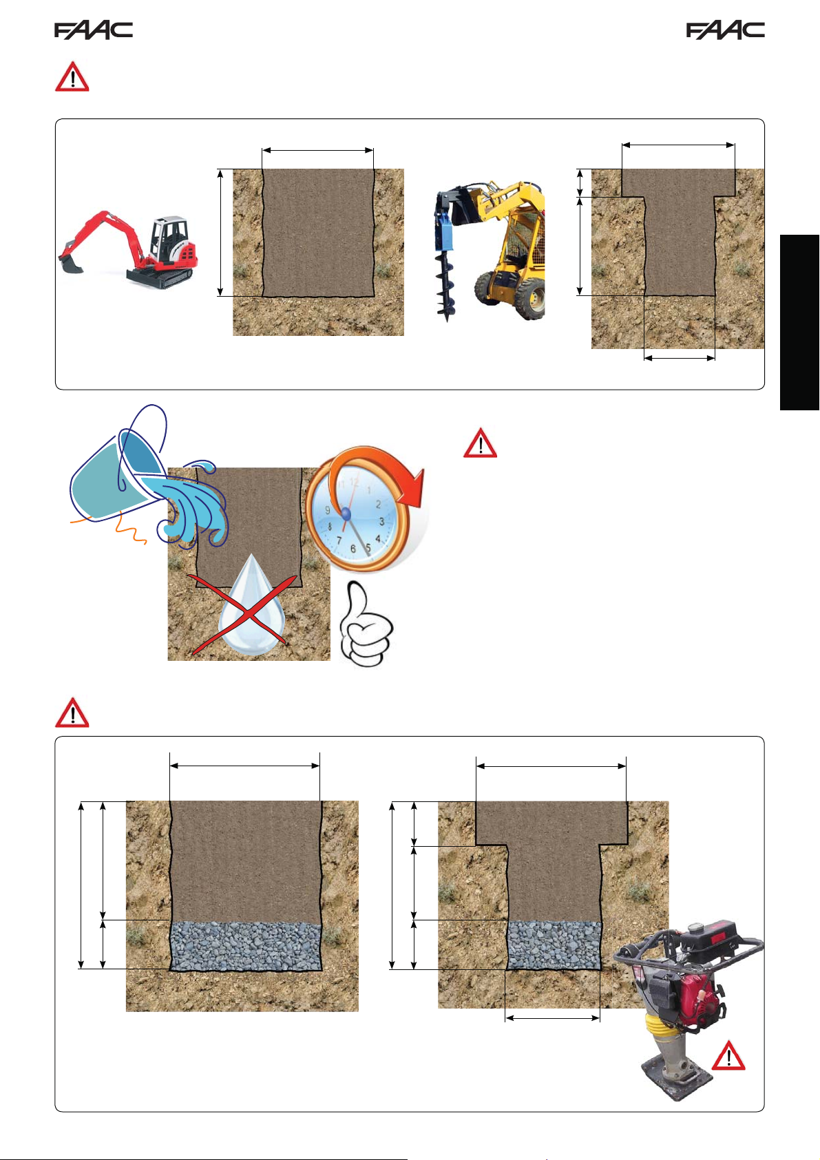
The dig can be square and have a side of about 1 m (fig. 3). Otherwise it can be carried out using an earth
drill with a diameter of 50 cm up to the depth mentioned above and widened in the last 30 cm giving a square
shape of 1 m per side
Dimensions in mm
1100
30’40lt
1000
1000
800 300
500
Make sure that the ground
is able to absorb water: pour
about 40 l water and evaluate if
draining requires less than 30
minutes. If this is not the case,
discharge rain water by means
of a pipeline with a diameter of
60mm connected to the drainage
system or, as an alternative,
connected to a pit, equipped
with a drainage system (such
as a motor pump), having a
depth greater than the pit for the
collection and drainage of rain
water
Fig. 3
ENGLISH
Introduce gravel (grain diameter: approx. 20 mm.) to obtain a thickness of about 30 cm, taking care to compact
it well to avoid future settlements
1000
1000
300
800
1100
300
1100
500
300
500
Fig. 4
5
Page 7

IPlace the two included grub screws on the threaded holes indicated in the following reference, then tighten
the two eyebolts and use them to lift and position the frame.
ENGLISH
Place the bollard taking care to position it
plumb. The top level of the frame must be
approx. 10 mm higher than the floor surface
(to limit the inlet of rainwater in the pit).
To reduce any stumble risk, level the pit to the
street surface.
Respect the direction of transit as shown in fig.5.
10
Fig. 5
With the bollard in place, enter additional 35mm of gravel, then lay a flexible sheat (external diameter = 40mm)
from the bollard to the control unit.
6
Page 8

GRAVEL
CONCRETE
FLEXIBLE SHEATH
STREET SURFACE
ø 40mm
Fig. 6
350300
Cast concrete, type RCK25, all around the pit to secure it firmly up to about 10cm from the floor surface. After
having secured the pit, finish the street surface using the same type of material.
Dimensions in mm
STREET SURFACE
1000
CONCRETE
800
350300
1000
800
ENGLISH
300
GRAVEL
Lay the pipelines that are necessary for the connection between the control unit and any additional device
(i.e. traffic lights – inductive loops – card reader – etc.) and every other bollards, if any. Prepare the electrical
connection and the earthing.
To connect the bollard to the control
board, use a cable, type FG7OR-0,6/1kV16G1,5, having a max. length of 50 m.
N.B.: every pipe must be laid in compliance
with the current rules.
At the end, remove the protective film
from the upper plates.
300
Fig. 7
7
Page 9

5 ELECTRIC WIRING
For the connection of the bollard to the control unit, use a multi-pole cable, type FG7OR-0,6/ kV- 6G 1,5 ( 16 cables of 1,5mm2)
with max. length of 50 m. This cable must be laid inside a sheath ø 40mm.
Perform the electric wiring in the junction box on the bollard side, as shown in the figure below. For easier wiring, the junction box
can be removed.
Any additional accessory (i.e. photocells, opening/closing push-buttons, etc.), that have to be connected to
the control unit, must compulsorily have double insulation.
ENGLISH
Earth
Motor phase
Motor neutral wire
Motor phase
+24V
Lights
Limit switch UP N.C.
Limit switch DOWN N.C.
{
{
Fig. 8
8
Page 10

6 MANUAL OPERATION
To lower the bollard by hand, you need to act on the release device.
1. Loosen the closing screw located on the bollard head (fig.
9 ref.
).
2. Introduce the supplied key into the relevant hole.
3. Turn counter-clockwise to lower the bollard (fig. 9 ref.
).
Fig. 9
8 STANDARD PROCEDURE FOR A 6-MONTHLY VERIFY
Ordinary maintenance standard procedure:
1. Clean the pit and remove any settled material by suction
2. Clean the water drainage systems on the pit bottom
3. Check (and repair, if necessary) any oil leakages from the
driving piston
4. Check the correct tightening of the bollard screws
5. Clean the driven cylinder and touch up paint, if necessary
6. Check the hydraulic unit and top up oil, if necessary. Check
the setting of the operating pressure
7. Check and set, if installed, the functions of the safety pressure
switch (40 Kg.)
7 AUTOMATIC OPERATION
To restore the automatic operation:
1. Introduce the supplied key into the relevant hole.
).
Fig. 10
2. Turn clockwise till end of stroke (fig. 10 ref.
3. Tighten again the closing screw on the bollard head (fig. 10
).
ref.
We advise to perform the abovwe mentioned operation at least
every six months.
ENGLISH
9
Page 11

JE275 CONTROL UNIT
The JE275 control unit is supplied with the control board 624 BLD and the housing, model E.
Always cut the power supply before performing any intervention on the control unit (connections, maintenance).
- Install a differential thermal-magnetic switch with suitable threshold (0.03A) upstream of the system.
- Connect the earth cable to the relevant terminal on the connector J9 of the unit (see figure below).
- Check if the power disconnecting switch is provided with locking key exept if it’s installed under operator/
maintenance man control.
- The control unit installation must be done between 0,4 m and 2,0 m height
9 ELECTRICAL CONNECTIONS
BOLLARD SIDE624BLD BOARD SIDE
ENGLISH
Motor
{
Motor
Lights
+24V
230Vac ~
{
+24V
+24V
Lights
Limit switch
UP
Limit switch
DOWN
Limit switch DOWN
10
Limit switch UP
Fig. 11
Page 12

10 PRE-SETTING SELECTION
After having connected the board and after having supplied it with power according to the previous paragraph, you must select the
work pre-setting for the bollard J200HA following the operations below:
1. Enter the 1
on the display.
2. Release key F and select 07 with the key +
3. Simultaneously press keys F and - to exit programming and save the changes performed.
For any further information on the unit programming, please refer to the relevant
instructions.
st
level programming, holding down key F on the board. The initials dF will appear
11 POSITIONING THE LOOPS
Below you will find some examples for the realization of magnetic loops with one or more bollards:
1. Installation of a single bollard and two magnetic loops to detect vehicle transit.
2. Installation of a single bollard and of a magnetic loop to protect the perimeter.
3. Installation of four bollards (on a single 624BLD) and four loops to protect large passages
4. Installation of eight bollards (4 on 624BLD MASTER board + 4 on 624BLD SLAVE board, see par. 12.2) and eight loops to
protect large passages
The loops must be realized according to the instructions provided for the magnetic detector (control unit); they must be connected
each other in series or you can use more magnetic detectors and connect the relevant relay contacts in series.
200 cm
100 cm
ENGLISH
200 cm
60 cm
60 cm
100 cm
100 cm
100 cm
100 cm
100 cm
624BLD MASTER 624BLD SLAVE
11
Fig. 12
Page 13

12 CONNECTING MORE BOLLARDS
12.1 CONNECTION OF UP TO 4 BOLLARDS ON A SINGLE BOARD
Up to 4 bollards can be connected to the same unit and operate simultaneously.
Follow the instructions below for a correct wiring and operation (par. 12.3).
ENGLISH
Fig. 13
12.2 CONNECTION OF UP TO 8 BOLLARDS ON TWO 624BLD MASTER – SLAVE CONNECTION
You can connect 2 624BLD units in a MASTER-SLAVE configuration for the simultaneous control of 8 bollards. Follow the instructions
below for a correct wiring and operation (par.12.4).
Fig. 14
12
Page 14

12.3 WIRING OF UP TO 4 BOLLARDS ON A SINGLE BOARD
Connection of 4 motors Connection of lights / buzzer
BOARD SIDE
BOLLARD SIDE
Fig. 15
BOLLARD SIDE
Lights 1
Buzzer 1
Lights 2
Buzzer 2
Lights 3
Buzzer 3
Lights 4
Buzzer 4
BOARD SIDE
ENGLISH
Fig. 16
Connection of 4 limit switches DOWN in parallel.
The bollards stop when all 4 limit switches
are engaged
BOLLARD SIDE BOARD SIDE BOLLARD SIDE BOARD SIDE
Limit switch
DOWN 1
Limit switch
DOWN 2
Limit switch
DOWN 3
Limit switch
DOWN 4
Fig. 17
Connection of 4 limit switches UP in parallel.
The bollards stop when all 4 limit switches
are engaged
Limit switch
UP 1
Limit switch
UP 2
Limit switch
UP 3
Limit switch
UP 4
Connection of 4 pressure switches in series.
The fi rst operation of a pressure switch causes the
reversal of all bollards
BOLLARD SIDE BOARD SIDE
Pressure switch
1
Fig. 18
Pressure switch
2
Pressure switch
3
Pressure switch
4
Fig. 19
13
Page 15

12.4 WIRING OF UP TO 8 BOLLARDS ON TWO 624BLD IN MASTER – SLAVE CONNECTION
ENGLISH
DOWN 5
Limit switch
DOWN 6
Limit switch
UP 5
UP 6
Limit switch
DOWN 7
DOWN 8
Limit switch
UP 7
UP 8
Buzzer 1
Buzzer 2
Light 5
Light 6
Buzzer 3
Buzzer 4
Light 7
Light 8
Buzzer 5
Buzzer 6
Buzzer 7
Buzzer 8
Limit switch
Limit switch
Limit switch
DOWN 1
Limit switch
DOWN 2
Limit switch
Limit switch
Limit switch
DOWN 3
DOWN 3
Limit switch
Light 1
Light 2
Light 3
Light 4
UP 1
UP 2
Limit switch
Limit switch
Limit switch
UP 3
UP 4
Limit switch
14
1
2
3
Pressure switch
Pressure switch
Pressure switch
4
5
6
Pressure switch
Pressure switch
Pressure switch
7
8
Pressure switch
Pressure switch
Fig. 20
Page 16

13 TROUBLESHOOTING
The indications below will help you locate and solve particular conditions.
CONDITION ADVICE
1 The bollard rises for a few centime-
tres and then lowers immediately
2 As soon as the bollard reaches the
position, it reverses immediately
3 The bollard does not rise, it remains
down.
4 The bollard remains up in closed
position.
5 The buzzer and the LED fl ashing
lamp do not operate
• Make sure you have selected the default no. 7 on the 624BLD board
• Check if the safety pressure switch wiring was performed correctly, (optional,
see the related instructions)
• Make sure that the LED DL3 (FSW) on the 624BLD board remains ON for the
whole movement
• Adjust the pressure switch (if installed)
• Replace the pressure switch
• Check if the wiring of the limit stops was performed correctly, see fi g. 11 or fi g.
18
• Make sure that the up position limit stops are correctly positioned, see ref. 11
fi g.1
• Make sure you have selected the default no. 7 on the 624BLD board
• Check if the wiring of the solenoid valve was performed correctly, (optional, see
the related instructions)
• Check if the solenoid valve was adjusted correctly
• Replace the solenoid valve
• Make sure the bollard is hydraulically locked, see par. 7
• Make sure nothing between the cylinder and the sliding bush prevents the
bollard movement; try and shake the cylinder to facilitate its downstroke
• Make sure you have selected the default no. 7 on the 624BLD board
• Check if the power connector under the head was fi tted correctly
ENGLISH
14 CLEANING / UNMOUNTING PROCEDURE
In case you need to unmount / clean the bollard, proceed as follows. Each step (to be followed in sequence) allows for the access
to a different part of the bollard:
1) Top limit switch replacement
2) Headlight replacement
3) Cylinder removal for internal cleaning.
4) Piston removal and access to lower limit switch
a
b
15
Page 17

a
ENGLISH
b
16
Page 18

ENGLISH
N.B. Remove the oil pipe clamp before extracting thepiston
17
N.B. Remove the two chain fixing screws before extracting
the cylinder
Page 19

SEDE - HEADQUARTERS
FAAC S.p.A.
Via Calari, 10
40069 Zola Predosa (BO) - ITALY
Tel. +39 051 61724 - Fax +39 051 758518
www.faac.it - www.faacgroup.com
ASSISTENZA IN ITALIA
SEDE
tel. +39 051 6172501
www.faac.it/ita/assistenza
ROMA
tel +39 06 41206137
filiale.roma@faacgroup.com
SUBSIDIARIES
AUSTRIA
FAAC GMBH
Salzburg, Austria
tel. +43 662 8533950
www.faac.at
FAAC TUBULAR MOTORS
tel. +49 30 56796645
faactm.info@faacgroup.com
www.faac.at
AUSTRALIA
FAAC AUSTRALIA PTY LTD
Homebush – Sydney, Australia
tel. +61 2 87565644
www.faac.com.au
MILANO
tel +39 02 66011163
filiale.milano@faacgroup.com
TORINO
tel +39 011 6813997
filiale.torino@faacgroup.com
GERMANY
FAAC GMBH
Freilassing, Germany
tel. +49 8654 49810
www.faac.de
FAAC TUBULAR MOTORS
tel. +49 30 5679 6645
faactm.info@faacgroup.com
www.faac.de
INDIA
FAAC INDIA PVT. LTD
Noida – Delhi, India
tel. +91 120 3934100/4199
www.faacindia.com
PADOVA
tel +39 049 8700541
filiale.padova@faacgroup.com
FIRENZE
tel. +39 055 301194
filiale.firenze@faacgroup.com
BENELUX
FAAC BENELUX NV/SA
Brugge, Belgium
tel. +32 50 320202
www.faacbenelux.com
FAAC TUBULAR MOTORS
Schaapweg 30
NL-6063 BA Vlodrop, Netherlands
tel. +31 475 406014
faactm.info@faacgroup.com
www.faacbenelux.com
SWITZERLAND
FAAC AG
Altdorf, Switzerland
tel. +41 41 8713440
www.faac.ch
CHINA
FAAC SHANGHAI
Shanghai, China
tel. +86 21 68182970
www.faacgroup.cn
UNITED KINGDOM
FAAC UK LTD.
Basingstoke - Hampshire, UK
tel. +44 1256 318100
www.faac.co.uk
FRANCE
FAAC FRANCE
Saint Priest - Lyon, France
tel. +33 4 72218700
www.faac.fr
FAAC FRANCE - AGENCE PARIS
Massy - Paris, France
tel. +33 1 69191620
www.faac.fr
FAAC FRANCE - DEPARTEMENT VOLETS
Saint Denis de Pile - Bordeaux, France
tel. +33 5 57551890
fax +33 5 57742970
www.faac.fr
NORDIC REGIONS
FAAC NORDIC AB
Perstorp, Sweden
tel. +46 435 779500
www.faac.se
SPAIN
F.A.A.C. SA
San Sebastián de los Reyes.
Madrid, Spain
tel. +34 91 6613112
www.faac.es
U.S.A.
FAAC INTERNATIONAL INC
Jacksonville, FL - U.S.A.
tel. +1 904 4488952
www.faacusa.com
FAAC INTERNATIONAL INC
Fullerton, California - U.S.A.
tel. +1 714 446 9800
www.faacusa.com
POLAND
FAAC POLSKA SP.ZO.O
Warszawa, Poland
tel. +48 22 8141422
www.faac.pl
RUSSIA
FAAC RUSSIA LLC
Moscow, Russia
tel. +7 495 6462429
www.faac.ru
MIDDLE EAST
FAAC MIDDLE EAST BRANCH
Dubai Airport Free Zone - Dubai, UAE
tel. +971 42146733
www.faac.ae
732804 - Rev.A
 Loading...