

Page 1
Installation and Reference Manual
™
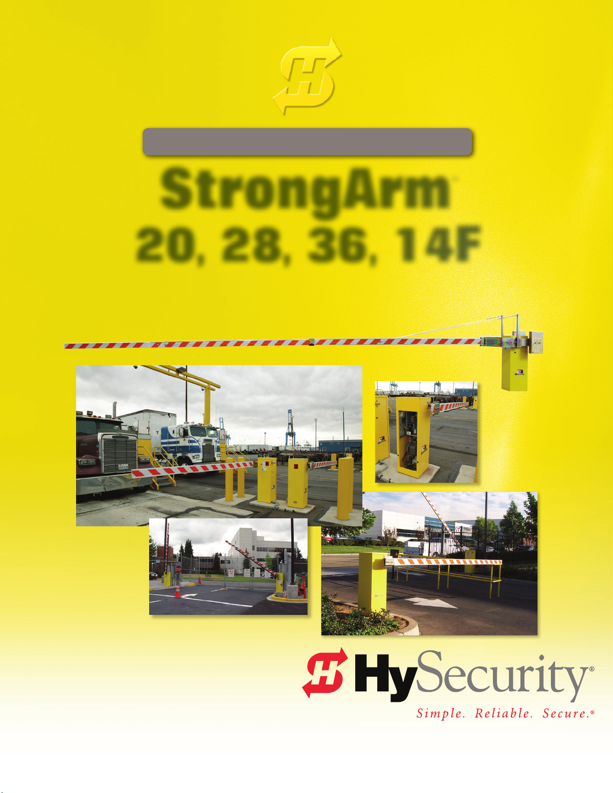
StrongArm
20, 28, 36, 14F
(HTG)
Hydraulic barrier gate operator with Smart Touch Controller
800-321-9947 • www.hysecurity.com
Page 2

Page 3

June 6, 2012
HySecurity Upgrades
Software:
User Programmable Output Relays
800-321-9947 www.hysecurity.com D0496 Rev A Page 1
Page 4
Alert and Error Codes
Display
Code
Error/Fault/Alert Description
Buzzer Chirp
Sequence
Possible Cause & Suggested Corrective Action
New Products from HySecurity
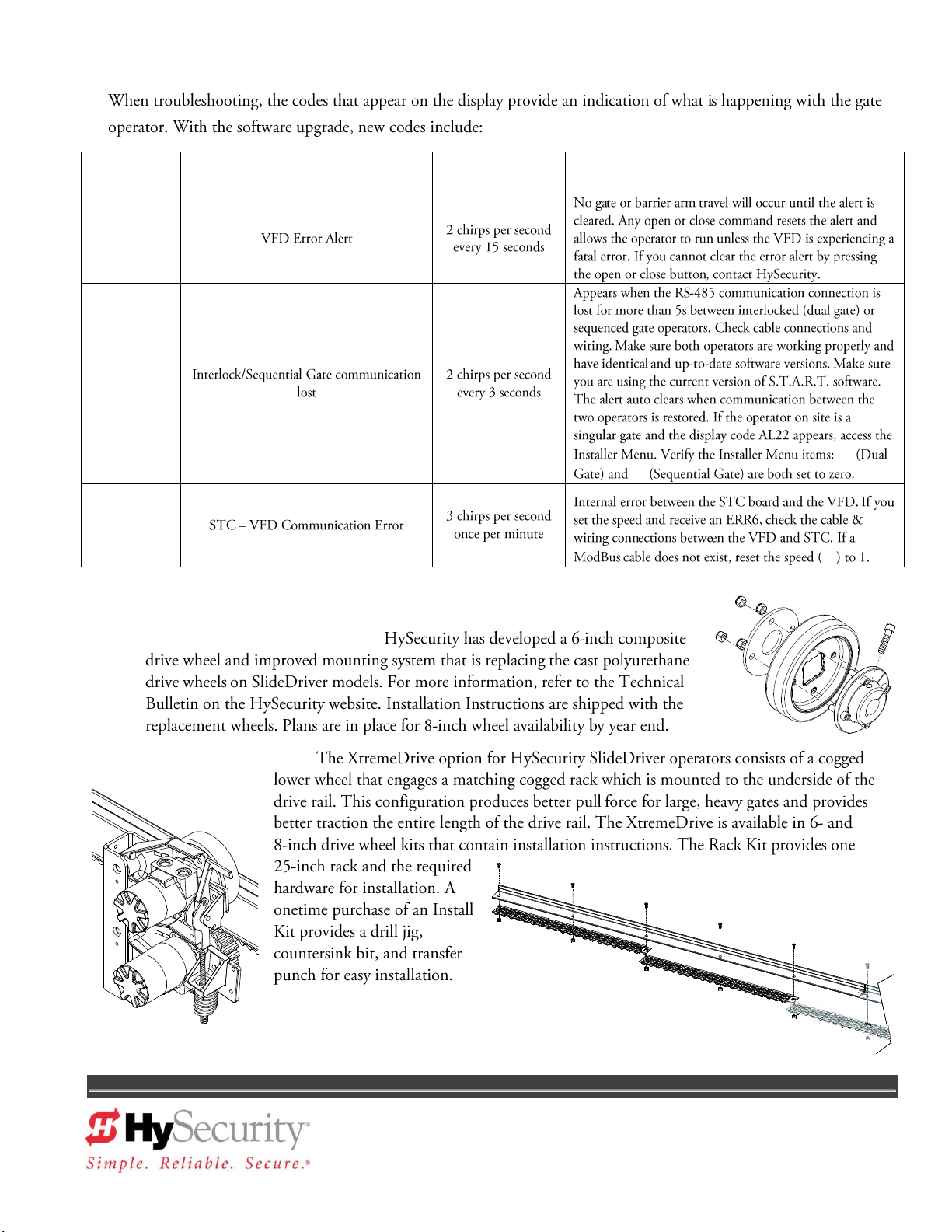
AdvanceDrive™ Wheel System:
XtremeDrive™ Option:
800-321-9947 www.hysecurity.com D0496 Rev A Page 2
Page 5

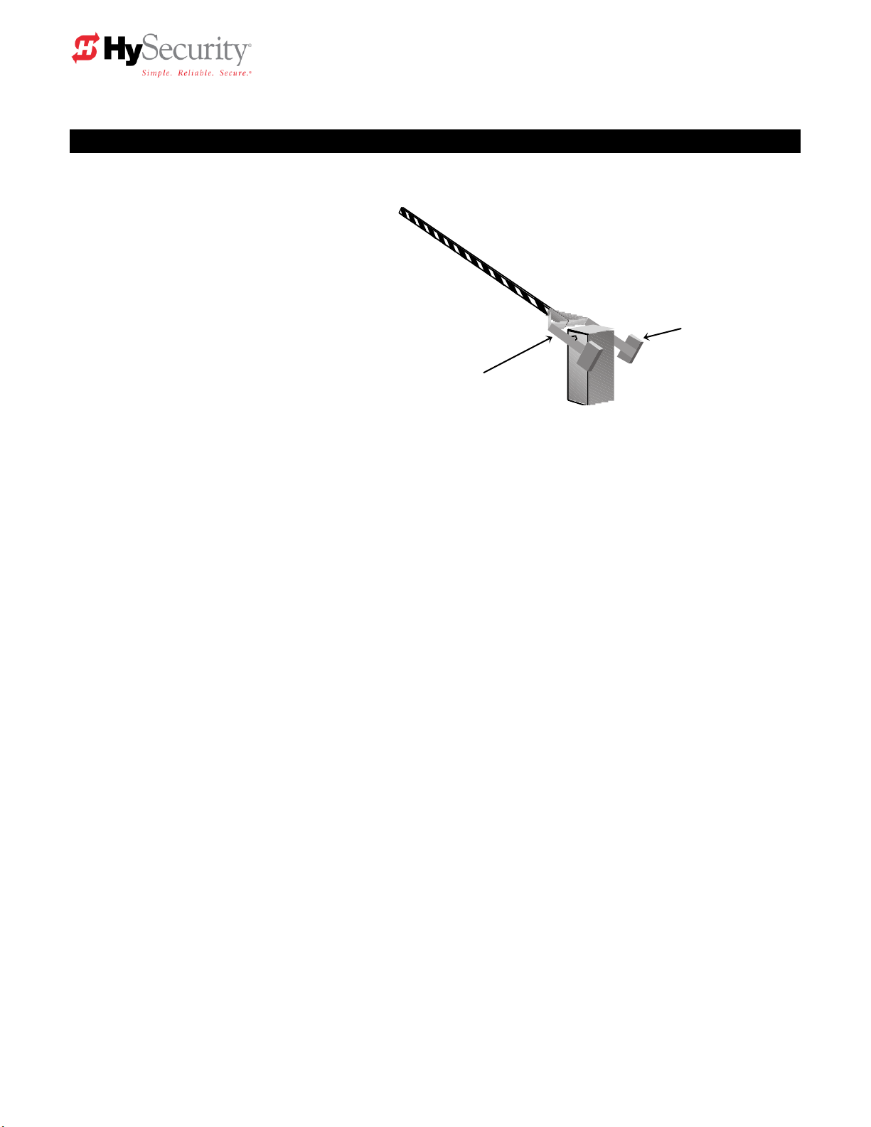
StrongArm (HTG 320) Barrier Arm Gate
Operator – Quick Start Instructions
These instructions are provided as a quick reference guide to the experienced installer that is already familiar with
all safety precautions and the installation of this gate operator. Do not attempt to install from this guide if you are
inexperienced with this product.
1. Using four 1/2‖ x 4 1/2‖ anchor bolts mount the operator to a concrete slab which reaches below the local
frost line. If necessary, use shims to level the base.
2. If installing the DC version of the operator, be careful to mount the battery power supply box very near the
control enclosure because of the high current demand by the DC motor. Note: For the DC version, refer
to Section 8 of the operator handbook.
3. Connect the electrical power to loose wires from the On/Off switch and a grounding wire to the lower left
corner of the electrical panel. Be certain the labeled voltage and phase of the operator matches the
available supply.
4. Turn on the power switch. The Smart Touch LCD display should show, after a 2-second delay, the
characters [uC_0]. This is a setting for the UL user class that must be made before any function will be
possible. Press the Select button, then the Next button and change the 0 to be class 1-4 as appropriate
for the site. Press the Select button again to lock the setting.
5. Press the Menu button and the display will jump to the close timer setting [Ct_0]. If a close timer function
is needed, set in the same manner as above. Press the Menu button again to exit to the Run Mode. The
LCD display should now read StoP, CloS or OPEn.
6. If the operator contains more than four counterweights per side, the arm must be mounted before the
gate operator can be allowed to function. Otherwise, test for normal operation of the gate.
7. Install the barrier arm and clamp securely. Single arms, up to 18’ maximum can be installed on either the
left or right side of the operator. Arms longer than 26’ include anti-sway cable harnesses that must also
be attached.
8. Run the operator and verify normal smooth operation. If the arm stops abruptly at the end of travel, it
may be necessary to adjust either of the open or close brake valves and/or a limit switch setting. There
are two brake valves on the pump manifold and the one closest to the motor controls the stopping of the
arm in the closing direction. The open direction stop control is with the brake valve just to the left. If
adjustment of either brake valve is necessary, loosen the 9/16‖ lock nut and turn the adjuster screw with
an Allen wrench. A CCW adjustment will stop the arm more quickly. The limits must be set to trigger
about 10 degrees of arc before the arm has reached full travel. If adjustment of the limit switches is
necessary, slightly loosen the set screws on the cams at the top of the operator and set the limits to trip
early enough to ensure a smooth stopping arm. For detailed instructions on barrier arm adjustments,
review the page titled StrongArm (HTG 320) Adjustments in the handbook.
9. Connect any required accessory device wiring. Note that the various inputs are all one wire only to the
main terminal strip while the other wire connects to the Common Buss on the nearby power supply board.
10. To access the User menu in the Smart Touch Controller, simply press the Menu button while there is no
active Open or Close input. The display will scroll system values and stop at the [Ct__] close timer
setting. There are 12 menu items in the User Menu. To reach the more detailed Installer menu, the
system must be in the User Menu first, then simultaneously press Open and Reset. The display will go to
[uC__] which is the first of 32 items in the Installer Menu. Read the instructions before attempting any
adjustments!
Page 6

Installation and Maintenance Manual
U1
[Ct 0] Close timer setting
0
0 = Close timer off or 1 – 99 seconds
U2
[hC 0] Momentary Close
0
0 = momentary, 1= Constant hold PB required to close gate
U3
[ho 0] Momentary Open
0
0 = momentary, 1= Constant hold PB required to open gate
U4
[AP 0] AC Power loss function
0
0 – 3 (0 =Type A, 1 = B, 2 = C, 3 = D) See handbook
U5
[ro 0] Radio control option
0
0 = Open only, 1 = Adds Close capability when fully open
U6
[bF 2] Warn before operate
0
0 = none, 1 = Buzzer alerts 3 sec before & when in motion,
2 = Buzzer alerts 3 sec before + first 2 seconds in motion
U7
[FA 0] Forced open Alert and
automatic gate reposition
0
0 = disabled, 1 sound buzzer (2 pulses/sec) if forced
open for more than four seconds, time out in 30 Sec
U8
[dA 0] Drift Closed Alert and
automatic gate reposition
0
0 = disabled, 1 sound buzzer (2 pulses/sec) if drift closed
and cannot reopen within four seconds.
U9
[PE 0] Photo Eye Align Mode
0
0= off, 1 = on (auto reset to 0 when close limit triggered)
U10
[CL 0] Clock set (24 hour type)
0
0= display, 1= set mins, 2= set hours, 3= set day, 4= month
U11
[Ld 5] LCD Contrast set
5
1 - 9 = Adjusts contrast of the display
U12
[dS 0] Data Log (New gen board only)
0
0 = Std. 1 = Extended (reset to 0 in 24 hr) (V4.xx software)
I1
[uC 0] Set UL Usage Class
0
0 = Gate disabled, Set Class 1 through 4 use
I1a
[bu 0] Choose Buzzer
0
0 = Buzzer not set, 1 = Freq 1, 2 = Freq. 2
I2
[Fd 0] Load Factory Defaults
0
0 = User Settings, 1 = Load defaults (resets entire menu)
I3
[dg 0] Set Master/Slave type
0
0 = Solo operator, 1 = Slave unit, 2 = Master unit
I4
[Ch 0] Set AC Charger or Solar
0
0 = DC + AC charger, 1 = DC + Solar charger
I5
[Fo 0] Enable Fire Dept. Open
0
0 = input disabled, 1 = enabled
I6
[oC 0] Enable Emergency close
0
0 = input disabled, 1 = enabled
I7
[SE 3] Inherent Sensor sensitivity
3
1 = Maximum sensitivity, 9 = Lowest sensitivity
I8
[SS 0] Inherent Sensor function
0
1 = stop only (note, functions in usage class 4 only)
I9
[LC 0] Leaf delay Close
0
0 = none (1-7) ½ second steps (Master/Slave only)
I10
[Lo 0] Leaf delay Open
0
0 = none (1-7) ½ second steps (Master/Slave only)
I11
[rt 0] Maximum run timer
0
0 = 60 Seconds max run, 1 = 300 Seconds max run
I12
[EC 0] PEC reverse to open
0
0 = Close eye stops only, 1 = 2 sec reverse to open
I13
[PC 0] Set PEC output – NO/NC
0
0 = Normally Open PE output, 1 = N.C. (Supervised mode)
I14
[gC 0] Set Edge input – NO/NC
0
0 = Normally Open Edge output, 1 = Normally Closed
I15
[tC 1] Time clock/ Interlock input
1
0 = select Time Clock, 1 = select Open Interlock
I15a
[dt 0] Disable Free Exit/Close Timer
0
0 = disable Free Exit, 1 = disable Close Timer
I16
[or 1] OOLD detector function
1
0 = pause closing only, 1 = enable reversing to open
I17
[ir 1] IOLD detector function
1
0 = pause closing only, 1 = enable reversing to open
I18
[Cr 1] RLD -Reset detector function
0
0 = Reopen if tripped while closing, 1 = Pause only
I19
[Cb 0] RLD -Reset detector function
0
0 = One way, 1 = Bi-directional - disables ELD if tripped first
I20
[CP 0] RLD -Reset detector function
0
0 = Std. Close, 1 = Count opens & closes after equal reset
I21
[Eb 0] ELD –Exit detector function
0
0 = Off, 1 = Enable ELD back off auto close feature
I22
[r1 0] User relay 1 option
1
0 = disabled, 1 – 24 = see relay output options page 26
I23
[r2 0] User relay 2 option
6
0 = disabled, 1 – 24 = see relay output options page 26
I24
[r3 0] User relay 3 option
1
0 = disabled, 1 – 24 = see relay output options page 26
I25
[tL 0] Gate Open alert
2
0 = 0 sec, 1= 15s, 2= 45s, 3= 75s, 4= 105s, 5= 135s
I26
[Lt 0] Loitering alert
3
0 = 0 sec, 1= 15s, 2= 45s, 3= 75s, 4= 105s, 5= 135s
I26a
[SA 0] System Address
0
0 = no network, 1-99 network ―drop‖ address
I27
[ELd0] Test factory ELD
0
0=Run, 1=show freq, 2=show call level 0-7, 3= set Freq 1-4
I28
[iLd0] Test factory IOLD
0
0=Run, 1=show freq, 2=show call level 0-7, 3= set Freq 1-4
I29
[oLd0] Test factory OOLD
0
0=Run, 1=show freq, 2=show call level 0-7, 3= set Freq 1-4
I30
[rLd0] Test factory RLD
0
0=Run, 1=show freq, 2=show call level 0-7, 3= set Freq 1-4
Smart Touch Controller Menu Guide for StrongArm (HTG 320)
To gain access to the User Menu, press the Menu button when the gate is stopped. The LCD will scroll through key
several items, then stop at the close timer setting [Ct ].
User Menu Options Default Description
Note for U6 – The Warn before operate buzzer is an accessory device for StrongArm (HTG 320)
operator.
To access Installer Menu, press the Open & Reset buttons together while in the User Menu.
Installer Menu Options Default Description
ii
Page 7

D0120 Rev C
1/31/2011
HySecurity
Gate Operators
HYDRAULIC
BARRIER ARM GATE
Operators
With Smart Touch Controller
Installation and Maintenance Manual
Models: HTG 320-2, HTG 320-3
HTG 320-6, HTG 320-8
and
DC Battery UPS version
Phone: 800-321-9947
FAX: 888-321-9946
Internet: www.hysecurity.com
Email: info@hysecurity.com
Page 8
Copyright Notice
Trademarks
Publication Information
Barrier Arm Gate Operator
©
C
o
p
y
r
i
g
h
t
2
0
0
1
H
y
-
S
e
c
u
r
i
t
y
G
a
t
e
I
n
c
.
Page 9

Table of Contents
Introduction ...................................................................................................................... 1
Warranty Registration ...................................................................................................... 2
Available Models and Features .................................................................................... 3-4
I. Safe Gate Design
Important Information for Gate System Installers, Owners & Users ....................... 5-6
Typical System Schematic for a Barrier Gate ................................................................ 7
Tools Required ................................................................................................................. 8
II. Installation
Installation Preparations and Installation ................................................................. 9-11
HTG 320 Components .................................................................................................... 12
HTG 320 Adjustments ................................ ................................ .................................... 13
Manual Operation ........................................................................................................... 14
Technical drawings ................................................................................................... 15-17
III. Smart Touch Set up
Basics of Using the Smart Touch Controller ............................................................... 18
Installation Configuration for Smart Touch Controller ............................................... 19
Wiring Control Inputs to the Smart Touch Controller ............................................ 20-21
Connecting a Master/Slave Pair .................................................................................... 22
Table of User and Installer Menu Functions ........................................................... 23-27
User Menu: Description Functions Available .............................................................. 25
Installer Menu: Description Functions Available ................................................... 26-27
Options for User Programmable Output Relays .......................................................... 28
Clock Functions ............................................................................................................. 29
IV. Entrapment Protection
Entrapment Protection Schematic ................................................................................ 30
UL 325 Standard Requirements for Entrapment Protection Devices ........................ 31
Placement and Use of Secondary Pedestrian Entrapment Sensors.......................... 32
Installing Gate Edge (Contact Type) Reversing Sensor ............................................. 32
Installing Photoelectric (Non-Contact) Sensor ....................................................... 33-34
Page 10

Table of Contents, continued
V. Detectors and Loops
Loop & Detector Installation Guide ......................................................................... 35-37
Vehicle Detector Options ............................................................................................... 38
HySecurity Hy-5A Vehicle Detector Installation .......................................................... 39
Standard 11-Pin Vehicle Detector Installation ............................................................. 40
Detector & Loop Fault Diagnostics ............................................................................... 41
VI. Accessories
24 Hr / 7 Day Time Clock Option .................................................................................. 42
Connecting a Radio Receiver ........................................................................................ 42
VII. Troubleshooting and Maintenance
Troubleshooting ....................................................................................................... 43-44
Maintenance ............................................................................................................. 45-46
VIII. Two part Operators (Battery types)
Important Notes about DC Powered Gates ................................................................. 47
DC Wiring & Control ..................................................................................................... 48
Battery Supply Diagrams ............................................................................................. 50
IX. Appendix
Wiring Size Schedules ............................................................................................. 51-52
Components & Replacement Parts ........................................................................ 53-59
Smart Touch Controller Connections ......................................................................... 60
StrongArm Brake Valve Adjustment Procedure......................................................... 61
Limited Warranty ........................................................................................................... 63
Page 11

Introduction
Welcome – We would like to take this opportunity to thank you for this
purchase. HySecurity has manufactured the finest hydraulic gate operators
available since the 1970s. Our commitment to quality and innovation will
become evident as you become familiar with the features and performance of
this expertly engineered machine. All HySecurity operators are equipped
with the Smart Touch Controller, a digital electronic brain that offers
unparalleled features.
Please take a few minutes to study the contents of this instruction manual.
The benefits of taking a little extra time to align the gate operator properly and
to verify a fully functional installation will ensure customer satisfaction and a
longer life with minimal maintenance costs.
Installers and owners must be certain to thoroughly review and
understand the Important Information regarding pedestrian entrapment
protection contained within this manual. There are hazards associated
with automatic gates that can be greatly reduced with proper design,
installation use. When an automatic gate is first made functional, the
installer must teach the owners and users how to operate this system
correctly. When the installation is complete, leave this manual for the
owner’s use and reference.
Please do not hesitate to give your HySecurity distributor a call if you
experience any difficulties during the installation. They are experienced and
trained to assist in resolving any problems.
StrongArm Installation and Reference 1
Page 12

PRODUCT & WARRANTY REGISTRATION
Enter the following information to register your HySecurity product. Please write legibly. Today’s Date:_____________________
NOTE: To extend the operator warranty beyond 1 year, you must return this registration within 60 days of purchase. Refer to the Limited Warranty.
Installer Information
First/Last Name: _________________________________________
Company Name: _________________________________________
Address: _______________________________________________
City: ____________________________ State/Province: __________
Country: _______________________ Postal Code: ____________
Daytime Phone: ___________________ Fax: __________________
E-mail: _________________________________________________
End-user Information
First/Last Name: _________________________________________
Company/Association: ____________________________________
Address: _______________________________________________
City: ____________________________ State/Province: __________
Country: _______________________ Postal Code: ____________
Daytime Phone: ___________________ Fax: __________________
E-mail: _________________________________________________
Product Information
Model name/number: ______________________________________
Serial number: ___________________________________________
Purchase Date: __________________________________________
Purchase Price: __________________________________________
Distributor’s name: _______________________________________
Distributor’s City: ________________________________________
Country: ________________________________________________
Installation Date: _________________________________________
Who is completing this form?
Installer End User Distributor
Maintenance Personnel Other ___________________
Additional Comments
_______________________________________________________
Did you visit the HySecurity website before purchasing your product?
Yes No
How did you hear about HySecurity gate operators? (Check all that apply.)
Advertisement Exhibition Distributor
Business associate Other (please specify): ____________________________________
What factor(s) most influenced your purchase? (Check all that apply.)
Performance Price Power
Reliability Brand Prior Experience
Recommendation Warranty Product Weight
Fax or Mail this completed form to:
HySecurity, Inc Fax: 888-321-9946
6623 South 228th Street Email: info@hysecurity.com
Kent, WA 98032
HySecurity provides product installation, maintenance and troubleshooting training. View opportunities online at the HySecurity website:
www.hysecurity.com/support. For Technical Support, call 800-321-9947.
HySecurity does not share this warranty registration information with third parties unless the requested services, transactions, or legal requirements necessitate it.
StrongArm Installation and Reference 2
Page 13
Model
StrongArm 14F
StrongArm 20
StrongArm 28
StrongArm 36
Part #
HTG 320-2
HTG 320-3
HTG 320-6
HTG 320-8
Duty Cycle
2,000 cycles/day
2,000 cycles/day
2,000 cycles/day
2,000 cycles/day
Arm Speed
2-sec. to open;
3-sec. to close
3-sec. to open;
4-sec. to close
5-sec. to open;
6-sec. to close
8-sec. to open;
8-sec. to close
Horsepower
¾ ¾ ¾
¾
Warranty
5 years
5 years
5 years
5 years
Soft Stop
Yes
Yes
Yes
Yes
Brake Valves
Yes
Yes
Yes
Yes
Soft Start
No
No
No
Yes
Arm Length
Up to 14'
Up to 20' (Side mount
available for arms up
to 18')
Up to 28'
Up to 36'
Arm Designs
Side mount
aluminum or
fiberglass (Wood up
to 14')
Side or center yoke
aluminum or
fiberglass (Wood up
to 14')
Center yoke
aluminum or
fiberglass
Center yoke
aluminum or
fiberglass
UL Class
1 - 4
1 - 4
1 - 4
1 - 4
Available Models and Features
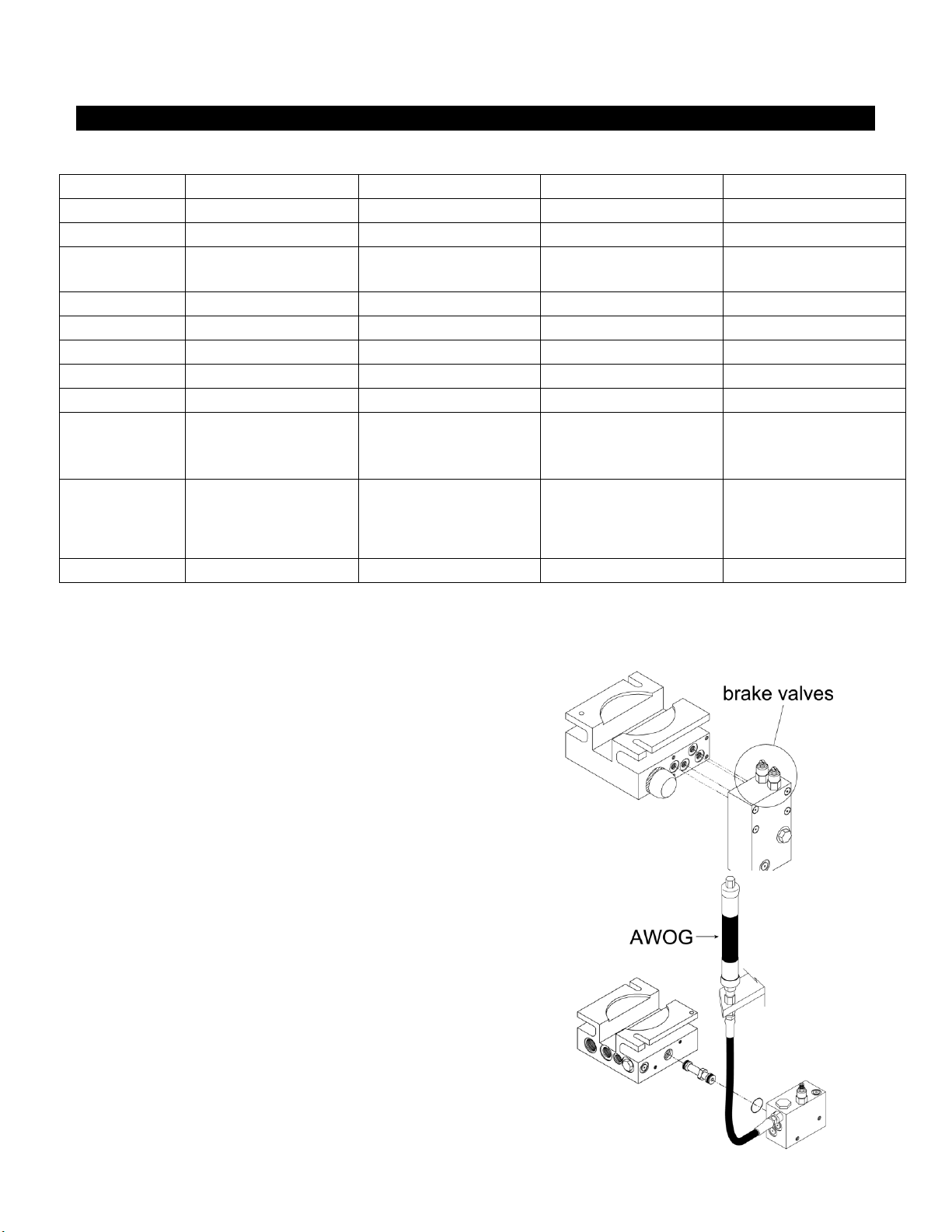
Stopping the Gate
All models employ a time delay Soft Stop system.
Additionally, brake valves (shown at right) are used to control
the smooth stopping of the gate. These valves are exclusive
to HySecurity’s operators. They are independently adjustable
to allow the gate to stop predictably without banging.
Starting the Gate
When starting very heavy barrier arms, it is necessary to Soft
Start the load gently, in addition to stopping it smoothly.
HySecurity accomplishes Soft Start with another exclusive
feature we call an AWOG, which diverts some of the start-up
hydraulic flow and thereby allows the gate to gently
accelerate. This is much like letting your foot slowly off a car
clutch – no lurching when the gate starts. The AWOG
improves the life and performance of a gate system and never
needs adjustment.
NOTE: This feature is standard on StrongArm 36 (HTG
320-8) only.
StrongArm Installation and Reference 3
Page 14
Counterweights
required for arms
over 18’
Heavy duty yoke
mount for arms
longer than 16’
Features:
Simple & Reliable Hydraulic Design
No gearbox, belts, linkages or clutches
to maintain
Design Rate: 2000 cycles per day
5-year Limited Warranty
Heavy Duty Components
¾ HP motor handles arms up to 36’ in
length
Anti-corrosion Finish
Entirely electroplated, then coated with
a high gloss powder paint finish. The
(-6 & -8 models are galvanized and
include a stainless steel cover)
The Smart Touch Controller (Standard)
This is the brain of the all HySecurity’s automatic operators. Truly high technology, but is also very rugged
to reliably serve in the harsh environments that exist in the real world. The Smart Touch Controller is also
very smart and can quickly be configured by an installer or user to adapt to about any functional
requirement of a specific site. All system settings are performed with the use of just five programming
buttons and an LCD display. The Smart Touch Controller has no switches of any type to set. An RS232
port is for external communication is standard. The system also has a real time clock and an EEPROM to
record system events. The log of events can be downloaded from the RS232 port with a PC and serial
cable. Our optional vehicle detector modules set a new industry standard by communicating a host of
valuable performance data to the microprocessor in the Smart Touch Controller via a serial data stream,
providing user-friendly diagnostics.
DC 24-Volt UPS Operators (Optional)
These gate operators function from 24 Volts DC all of the time to achieve a true UPS system. Our
Uninterruptible Power Supply is the most certain way to know that your gate will work when the AC
power fails. This system features fully sealed maintenance free batteries in a separate insulated and
ventilated enclosure. This two-battery system provides at least 1,000 full open & close operations in the
event of AC power loss.
StrongArm Installation and Reference 4
Available Models and Features
Page 15

-Danger-
Keep Away
Attention
-Take Note-
Entrapment
Zone
Possible
Pinch Point
Automatic gate operators provide convenience and security to users. However, because these
machines can produce high levels of force it is important that all gate operator system designers,
installers and end users be aware of the potential hazards associated with improperly designed, installed
or maintained systems. Keep in mind that the gate operator is only one component of the total gate
operating system. It is the joint responsibility of the specifier, designer, purchaser, installer and end user
to verify that the total system is appropriately configured for its intended use. All parties should be
informed that entrapment in a moving gate could cause serious injury or death.
Common
Industry
Symbols
Important Instructions for Gate System Designers & Installers:
WARNING: To reduce the risk of serious injury or death, read and follow all instructions in the
gate operator handbook and on the warning labels.
Install an Automatic Barrier Arm Gate Operator only When:
Automatic gates are for vehicular use only! Provide walkways and signs to direct
pedestrians and bicycles to a separate walk-through entrance. Because an
automatic gate can start at any time without warning, always keep people away
from the area of the gate. The Warning labels that have been supplied with this
operator must remain installed, in manner clearly visible, in the area of both sides
of the gate.
All exposed pinch points are to be guarded. To reduce the risk
of entrapment, the gate operator must also be installed so that at least two feet of
clearance is provided between the operator, barrier arm and adjacent structures
both when opening and closing.
The barrier arm must not to be modified in any way that creates a risk of
entrapment or a possibility that some portion of the moving arm could snag onto
the clothing of a pedestrian that happened to be nearby. Specifically prohibited
are any chains or other material attached to the barrier arm that may create such
a hazard.
StrongArm Installation and Reference 5
READ THIS FIRST!
Important Information – Review Before Installation
Page 16

Install An Automatic Barrier Arm Gate Operator Only When:
The operator will be properly electrically grounded and the intended supply voltage matches
the voltage label on the operator.
The controls that operate the gate have been mounted far enough away from the moving
gate such that users cannot touch the gate while operating the controls. All easily
accessible controls must have a security feature to prevent unauthorized use.
The operator controls will be located in a clear line-of-sight to the gate. Radio controls and
other remote access controls must be connected only to the Remote Open input.
The required external entrapment sensors will also be installed. Be certain to carefully
review the instructions for placement, installation and adjustment of these external
entrapment sensors. If edge (contact) sensors are used, they are to be mounted on the
bottom edge, of the arm. If photo eyes or other non-contact sensors are used, they are to
be mounted in locations most likely to guard against entrapment. A combination of contact
and non-contact sensors may be used, but all must be recognized components under the
UL 325 standard. See pages 34 and 35 for details on the requirements.
If the Entrapment protection is provided by a continuous pressure actuation control, a
placard stating ―WARNING‖ – ―Moving Gate has the Potential of Inflicting Injury or Death -
Do Not Start Gate Unless Path is Clear.‖ Additionally, no other activation device shall be
connected and an automatic closing device of any kind shall not be used.
The automatic operator is labeled as appropriate for both the type and UL usage class of
the gate.
Class I: Intended to serve single to four family residential uses
Class II: Multi-family use, or any application intended to serve the general public
Class III: Commercial applications not intended to serve the general public
Class IV: Highest security. Security personnel prevent unauthorized access
The barrier arm must not be installed in a manner that will move toward a rigid object closer
than two feet.
StrongArm Installation and Reference 6
Page 17
Important Information for Gate System Owners & Users
WARNING: To reduce the risk of serious injury or death, read and follow all instructions in the
gate operator handbook and on the warning labels.
Save These Important Owner and User Instructions:
(Installers – be certain to instruct the owners and users about the following items)
Automatic gates are for vehicular use only! Provide walkways and signs to direct
pedestrians and bicycles to a separate walk-through entrance. Because an automatic
gate can start at any time without warning, ALWAYS KEEP PEOPLE AWAY FROM
THE AREA OF THE GATE. The Warning labels that have been supplied with this
operator must remain installed, in manner clearly visible, on both sides of the gate.
Never allow children to use or play with controls that operate the gate. Keep all
remote controls, especially radio transmitters, away from children.
Teach all users how to turn off the electric power and how to release and move the
gate manually. Use the manual release only when the gate is not moving.
KEEP AUTOMATIC GATES PROPERLY MAINTAINED. Have a professional gate
installer perform routine tests of the entrapment protection sensors, such as photo
eyes and gate edges.
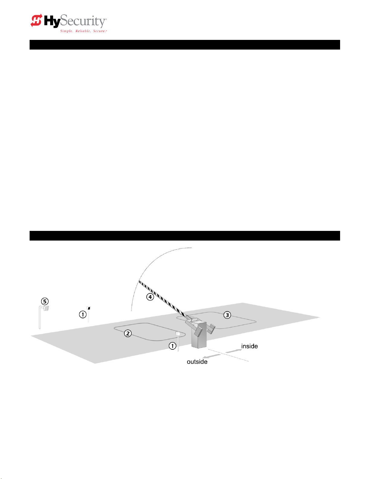
Typical System Schematic for a Barrier Gate
The following is a sample plan that incorporates the common elements of a typical bi-directional automatic
barrier arm gate.
1. A Photo eye helps to protect pedestrians that may stray into the path of the barrier arm.
2. An in ground vehicle sensing loop (reset function) to control closure, so that arm closes immediately when
a vehicle clears the barrier arm path.
3. An in ground vehicle sensing loop (free exit) activates the gate to open automatically from the inside.
4. Edge sensor to re-open the arm if an obstruction is encountered.
5. Gate entry device (card reader, telephone entry, keypad, etc) opens the gate after proper input from vehicle
driver.
StrongArm Installation and Reference 7
Page 18
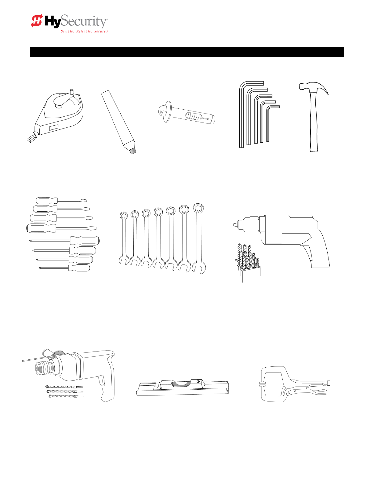
5. Hammer
6. Screwdriver sets,
Straight and Phillips
7. Wrench set, open end,
1/4" through 1"
8. Electric drill and bits,
1/8" through 3/8"
9. Roto-hammer and bits,
3/8" & 1/2"
10. Level—it doesn’t need to look
like this one, but the installation
needs to be level!
11. Two pair wide jaw vice
grip pliers, or two C clamps,
4" capacity
4. Allen wrench set
3. Concrete anchor
bolts, four 1/2" x 4"
2. Carpenters
pencil or crayon
1. Chalkline or other
builders string
Tools Required for an Efficient Installation
StrongArm Installation and Reference 8
Page 19
Installation Preparation Checklist
1. Read all of the instructions, especially the
Important Information in Section 1 at the
beginning of this manual, before you attempt
installation. This section is focused upon
mechanical installation. For electrical setup,
refer to Section 3, on system configuration
and use of the Smart Touch Controller.
2. Pour a concrete mounting slab that is a
minimum of 20‖ x 20‖ x 20‖ with the electrical
conduits located correctly to enter the
chassis. Keep in mind that a space of 7 X 11‖
just inside of the operator door is where the
conduits must enter into the operator.
HySecurity recommends a slab reaches
below the local frost line. See the footprint
plan and elevation view on pages 13-15.
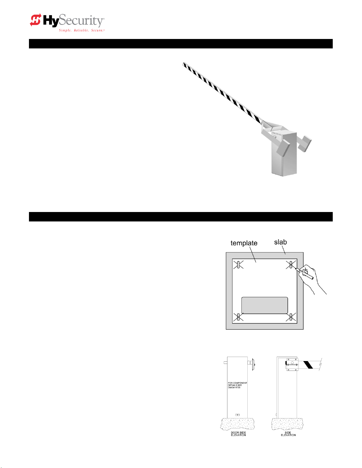
1. Drill four holes for concrete anchors
The operator must be mounted with four anchor bolts.
These will be 12.5‖ on center with a square pattern to
match the chassis base. Line up the operator so that the
end of the barrier arm is in the intended position. Place
the operator over the conduit and mark the mounting
holes. Once marked, remove the operator and drill for
½‖ min. anchor bolts.
2. Line up the operator
Set the operator over the mounting bolts, align the
operator and securely tighten the bolts.
3. Special two part operators
DC powered operators come with a separate power
enclosure. This enclosure should be mounted
within 20 feet of the operator. We recommend wall
mounting or using two 4‖ posts, with horizontal
mounting strut to create a support for this
enclosure. See also step 6 and section 8 on two
part operators.
Installation
StrongArm Installation and Reference 9
Page 20
Installation
4. Electrical power Connection
This operator is intended for permanent
installation, so all electrical conduits must be
properly connected to the control box. The
entry for the primary power is a ½ - ¾‖ knockout
on the left side of our control box next to the onoff switch. This operator was built to run on a
specific voltage and phase for line power. Make
sure the available line voltage and phase
matches the nameplate on this machine. Also
be certain that the wire size of the branch circuit
vs. the distance of the run from the main panel
is large enough to avoid excess voltage drop. At
a minimum, a 20 amp circuit (protected with a
20 Amp Inverse Time Breaker) should be
provided. Also be sure the operator is
electrically well grounded per NEC Article 250
and local codes. See the Appendix section for correct wire sizes and detailed electrical wiring
information.
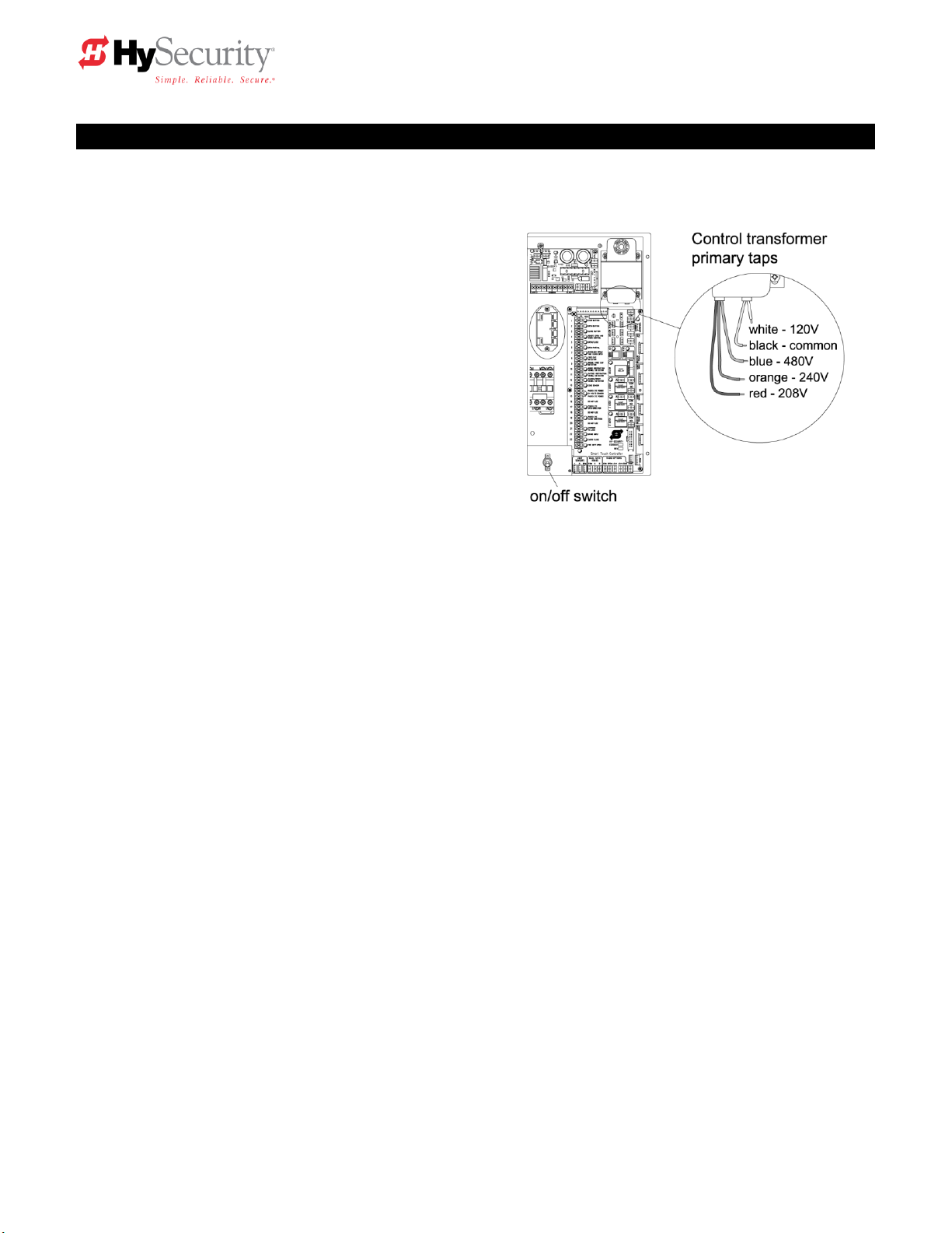
5. Primary tap of Control Transformer (not on DC battery powered operators)
Check to make sure that the primary tap on the control transformer matches the line voltage you
have connected to the operator. Measure the line voltage carefully to distinguish between 208V
and 230V branch circuits. A label on top of the transformer identifies the various taps.
6. Power Connection for Two Part Battery Operators
The primary AC power must be routed to the DC power supply enclosure, but there must
conduits between the gate operator and the DC supply enclosure. Note: AC power is not needed
in the gate operator enclosure, unless there is an optional heater. Three separate DC circuits are
required between the battery supply and the gate operator. Heavy gage wires to supply the
motor and two 14-gage circuits for the controls. The heavy gauge wire must be at least 6-gauge
if the DC supply is within 20 feet of the operator, but must be increased to 2-gauge if the DC
supply is located farther from the operator. For full details, review the section titled ―Two Part
Operators‖.
7. Replace the Vent Plug!
Remove the ½‖ steel or plastic shipping plug on the pump manifold (left rear corner) and replace it
with the supplied black breather cap.
8. Configuring the Smart Touch Controller
The operator controls will not allow the gate to function until the Smart Touch Controller has been
configured. Wait to connect the external controls until you have reviewed the Smart Touch
Controller instructions, and tested the basic functions of the operator. Review the Smart Touch
Setup section.
StrongArm Installation and Reference 10
Page 21

Installation
Attaching Barrier Arms to the Operator
1. Bolt arm(s) to operator. The maximum length for a single wood board is 14' length. Wood arms that
are longer than 14' must be twin arms bolted together near the tip.
2. Counterweights must be used for all arms over 18' in length, to assure proper performance. Verify
proper balance by following step #2 on StrongArm (HTG 320) adjustments page.
3. Tubular aluminum arms may be single side mounted up to 18’ in length. All arms over 18’ must be
mounted into a center yoke adapter. Arms longer than 24’ are aluminum/fiberglass and include
cables to make the arm more rigid, see the arm drawings for their proper location and installation.
Basic Testing
Test the operator for smooth control of the barrier arm. The arm should stop smoothly at each end of
travel. If any adjustments are necessary, carefully review the StrongArm (HTG 320) adjustments page.
Do not leave the job site without correcting an operator that is stopping abruptly on its limits or damage to
the mechanical drive components may occur.
If your operator is equipped with vehicle detectors, be certain that they are either unplugged or
connected to a loop so that they do not cause interference with the function of the machine. If the motor
turns, but nothing moves, reverse two poles of a three-phase power source, and/or verify that the bypass
valve is closed. To check the bypass valve, verify that the round black knob near the hydraulic hose
connection point on the pump is not toggled to the bypass position. See drawing HTC35 ST on page 12.
Install Accessory Items
1. After all basic functions are verified, and adjustments made, connect any accessory or external
control wiring.
2. Vehicle detectors: If vehicle detectors are to be used, review the section pertaining to detector
loop sizing and layout.
3. Button station operation: Install the push button control within sight of the gate arm. Be certain the
opening is clear before closing gate. Mount a sign, which advises that the area be clear before
operation, adjacent to button station.
4. Protection: Mount a photo eye below the arm and/or an edge sensor to the leading edge of gate
according to its manufacturers specifications.
Install Warning Signs And Safety Information Labels
1. Be sure to install all of the warning signs or labels that were supplied with this operator. If
these labels have been misplaced or lost, call your local distributor or the factory for
replacements.
StrongArm Installation and Reference 11
Page 22
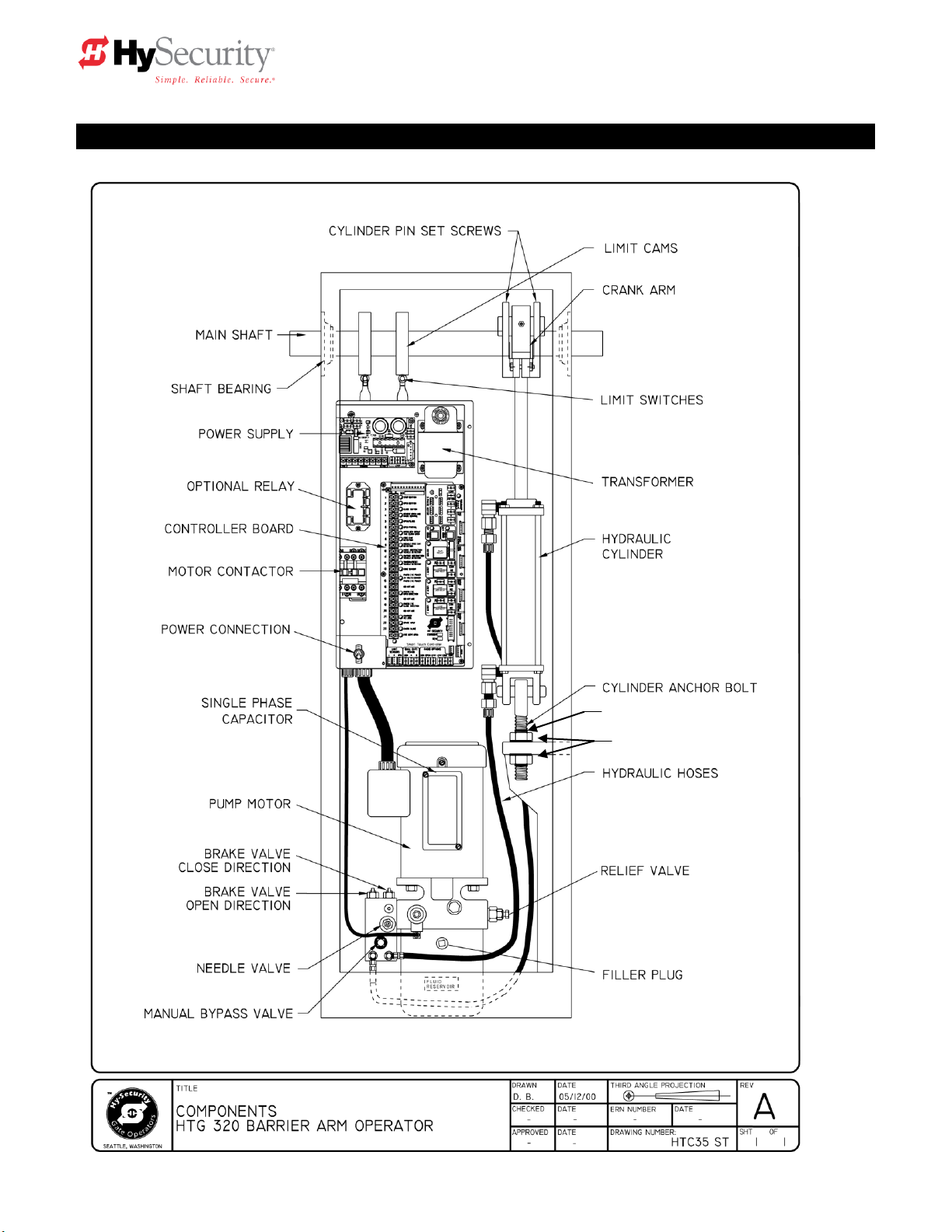
C-CLIPS (above & below nuts)
LOCK WASHERS & NUTS
Components of the Barrier Arm Gate Operator
StrongArm Installation and Reference 12
Page 23

StrongArm (HTG 320) Adjustments
The StrongArm (HTG 320) gate operator is pre-adjusted at the factory to perform correctly with the
barrier arm shipped. If the arm length, or weight is changed, it may be necessary to re-adjust the gate
operator to perform correctly. To properly adjust the StrongArm gate operator, perform all adjustments
in the sequence listed. Be certain to disconnect the power before performing any adjustments!
Arm Leveling: To adjust the gate arm with the threaded eyebolt at the base of the hydraulic cylinder
(see drawing HTC35 ST on page 12), take the following steps:
CAUTION: DO NOT remove the pin from the eyebolt. Neither the hydraulic cylinder nor the eye
bolt needs to be removed to adjust the gate arm height.
1. With the gate in the closed position, use a needle-nose pliers to remove the top and bottom
safety C-clips from the eye bolt.
2. Use a 1½-inch wrench to loosen the top nut to release tension on the eye bolt.
3. Move the gate arm and stabilize it at a level position.
4. To maintain the level position, hand-adjust the bottom nut up or down.
Note: You may initially need to unscrew the bottom nut to allow the gate arm to reach a level
position.
5. To lock the gate arm’s level position, tighten the top nut. Nut torque should be at least 100 ft-lbs
to prevent loosening during extended operation.
6. Re-insert the top and bottom safety C-clips so a gap (less than 1/8 inch) is
between the nut and C-clips.
7. Run a gate test by cycling the gate arm open and closed.
8. If the arm height needs further adjustment, repeat steps 1 through 7.
Balance: Before adjustments can be performed correctly, the operating weight of the arm must be
verified to be within the proper range for this machine. NOTE: All arms longer than 18' require
counterweight. If this is a new installation using a factory supplied arm, and no additional components
have been added, this test is not required because the factory has already provided the correct
counterweight for the arm as ordered. To determine the operating weight of the arm, first pull and twist
release the manual bypass valve (see drawing HTC35 ST on page 12), then manually lift the arm from
a position ten feet distant from the operator. The arm should appear to weigh forty pounds, or less,
regardless of the length or actual weight of the arm. If the operating weight of the arm is heavier than
our maximum specification, the operator is overloaded which adversely affects both automatic and
manual operation. The only remedy for an arm that is too heavy is to reduce the length of the arm, or
add additional counterweight.
Limit Switches: For the arm to stop smoothly, when opening or closing, the limit switches must trip
approximately ten degrees before the arm achieves full travel. If adjustments are necessary, use an
Allen wrench to adjust the cam collars on the drive shaft (see drawing HTC35 ST on page 12).
StrongArm Installation and Reference 13
Page 24

Brake Valves: When the limit switches are correctly set to trip a little early, the speed of the barrier
arm may decelerated to allow smooth stops. The rate of deceleration is adjusted by the red colored
brake valves, one for each direction of travel. The brake valve closest to the electric motor controls the
close direction (see drawing HTC35 ST on page 12). The brake valve on the left controls the open
direction. If adjustment of a brake valve is necessary, loosen the 9/16" lock nut and turn the adjuster
screw, in ¼ turn increments, with an Allen wrench. The adjustment works opposite of typical, such that
a counter-clockwise will stop the arm more rapidly. The correct brake valve adjustment will allow the
arm to smoothly stop just before the arm reaches full travel. Tighten the 9/16" lock nut on the brake
valve when complete.
Note 1: The brake valves do not control the closing of the arm when the manual bypass knob is pulled.
For adjustment of the manual mode, see step #3 on page 14.
Note 2: Careful adjustment of the open limit switch and brake valve may be especially important in
installations where there is truck traffic and the gate operator is close to the edge of the road. Be aware
that the later the open limit switch trips when the gate is opening, the sooner the open circuit will be
able to accept a safety reverse when the arm is closing. The best adjustment requires a rapid, but
smooth, stop of the arm at the end of the open cycle.
StrongArm (HTG 320) Manual Operation
A bypass valve has been provided that can override the hydraulic lock that normally secures the arm
from being lifted. In the event of a power failure, manual operation is achieved through the following
procedure.
1. Find the manual bypass valve with the black round knob, which is located on the hydraulic pump
just above where the hoses connect. (See drawing HTC35 ST on page 10). Pull and twist the
valve to engage the manual mode. The barrier arm can now be manually lifted, beginning from
the tip, by moving ―hand over hand‖ while walking towards the operator. When the arm is open,
be certain to close the bypass valve to prevent the arm from drifting down.
2. The arm can be manually closed with the same procedure, except that once manually started, the
arm will fully close itself due to the force of gravity.
3. To regulate the speed of closing, during manual operation only, there is a needle valve for flow
adjustment, which is located just above the manual bypass valve (see drawing HTC35 ST on
page 10). If adjustment is necessary, loosen the lock nut and turn the adjuster stem clockwise to
slow the rate of manual closure. The correct adjustment allows the arm to close at a moderate
speed and stop without excessive bouncing at the fully closed position.
StrongArm Installation and Reference 14
Page 25

46 ¾”
StrongArm Installation and Reference 15
Page 26

46 ¾”
StrongArm Installation and Reference 16
Page 27

StrongArm Installation and Reference 17
Page 28

Basics of Using the Smart Touch Controller System
Read this page if you are unfamiliar with using the Smart Touch Controller.
You must learn to navigate and change menu settings within the Smart Touch Controller before an
installation can be completed or any control settings or function changes can be made.
Until a new operator has been configured, the controls are not
functional and the display is locked in the menu mode until
the User Class 1-4, has been selected. See the next page for
instructions on how make this setting.
1. There are five buttons on the membrane switch pad that
provide control of everything. The Open, Close and Stop
buttons serve as a three-button control station, but in the
Menu Mode, they become Previous, Next and Select
buttons. The Program Menu button is used to both enter
and exit the Menu Mode. The Reset button clears all Errors
or Faults that may occur and returns the control to its
normal functioning state.
2. When in a Menu Mode, changes to be made to a Menu setting are accomplished by pressing the
Previous, Next and Select buttons in the following sequence:
a. Press the Next button to move forward through the list of menu items that are available,
as shown on pages 23 & 24, or press the Previous button to move back to an item that
you recently passed.
b. Press the Select button if you wish to make a setting change to a menu item. The menu
item will flash to indicate that its setting is ready to be changed.
c. Press Next to move forward or Previous to go back to an earlier setting choice.
d. When you have located the setting that you want to use, press the Select button and the
program will accept the change and stop blinking.
e. The Program Menu button does not allow an exit to Run Mode while a selection is still
blinking. Press the Select button to stop the blinking, then you may exit to Run Mode.
f. Pressing the Next or Previous buttons when the menu item is not blinking will move to the
next or previous menu item.
g. When done, press Program Menu to exit to the Run Mode.
3. Once configured, the operator will be in the Run Mode. From the Run Mode, to gain access the
User Menu or the Installer Menu, follow these steps:
a. Note that the Program Menu button will not function unless the gate is at rest and no open
or close inputs are active. Verify system status by pressing the LED button to disclose any
active inputs. There also must not be any Alerts, Faults or Errors. Press the Reset button
to clear the system if necessary.
StrongArm Installation and Reference 18
Page 29

b. Press the Program Menu button and watch the LCD scroll the system data, or press the
Program Menu key a 2nd time to skip the scroll. The scrolled data displays the information
in the table on page 23.
c. The LCD display scroll will stop at the menu item for the auto close timer setting
[Ct __]. This is the first item in the User Menu.
d. To access the more detailed Installer Menu, the system must first be in the User Menu,
and then simultaneously press the Reset button and the Open button. (Early software
versions require that the Menu button be pushed first and held while the Reset button is
pushed, then both buttons can be released) The LCD will change to display the UL usage
class menu item [uC __] This is the first item in the Installer Menu.
4. Pressing the Program Menu button when the User or Installer Menu is not blinking will return the
system to the Run Mode.
Installation Configuration for Smart Touch Controller for HTG
Basic Configuration and Setting of the Usage Class
1. Turn on the power switch and observe that the LCD will first show the software version, and then
stop at a steady display within two seconds. If the display reads [uC 0] go to step 2. If the
operator has previously been configured, the Installer Menu must be accessed in order to reach
the system configuration menu items: see step 3(d) at the top of this page.
2. When turning on the power for a new machine, the LCD display directly enters the Installer Menu
at the [uC __] menu item, which is for selecting the user class as defined by UL. Select [uC 1] [uC 2] - [uC 3] or [uC 4] depending upon the use application. See the entrapment Protection
Section for UL usage class definitions.
3. Once the usage class is set, you may want to configure some other menu items before exiting the
Installer Menu. The table below contains some common installer configuration items typical for a
barrier arm gate.
4. When ready to exit the installer Menu. press the Program Menu button. The LCD display jumps to
the close timer [Ct__] setting in the User menu, which may now be set. Either press the Program
Menu button again to exit to normal run mode or set the close timer by the same programming
sequence described at the previous page.
5. Note that the Installer menu cannot be exited by any means until the selection for the UL
usage class [uC __] has been entered.
StrongArm Installation and Reference 19
Page 30

1.
*Stop Push button N.C. input, jumper to Common if unused
2.
*Open Push Button Not for radio or remote access controls
3.
*Close Push button Not for radio or remote access controls
4.
Remote Open & Radio Control For radio / remote open device –
Program to also Close using Smart Touch menu
5.
Open/Close button Pushbutton or radio controls
6.
Partial Open (This input disabled on barrier arm gates)
7.
Open interlock input or Time clock Open Menu configurable
8.
Free Exit vehicle detector
9.
Disable Free Exit vehicle detector or Timer to Close
Free Exit is only disabled when Close Limit Switch tripped
10.
Inside Obstruction vehicle detector Inside reversing loop
11.
Outside Obstruction vehicle detector Outside reversing loop
12.
Reset vehicle detector (Closing loop under arm)
13.
Edge Sensor One input works for both travel directions
14-15.
Photo eye Common Power
Supply for PE power & PE Com
17.
Photo eye Open direction
19.
Photo eye Close direction
21.
Charger AC power loss Only used in DC, battery type operators
22.
Spare Input Software ≤ h3.26,- non functional,
Gate Lock Interlock Input Software > h3.26, prevents start until
external gate lock releases
23.
**Emergency Close Must menu enable and input +24 Volts to trigger.
Overrides photo eyes, gate edge & vehicle detectors.
24.
**Fire Dept. Open Must menu enable and input +24 Volts to trigger.
Overrides photo eyes & gate edge.
Wiring Control Inputs to the Smart Touch Controller
1. Test open and close before wiring the external control inputs. This makes it easier to troubleshoot
if an unexpected functionality arises. ―New Generation‖ Smart Touch Operator inputs (after Sept.
2006) use an LED to indicate when it is active. DC operators operating without AC require you to
push and hold an LED button to disclose input status. This button is in bottom corner near the
Fire Department Open input. [“Classic,‖ pre-Sept. 2006 operators LEDs are only lit when you
push the Tact button. The Tact button is located on the top left corner, near the Stop Button input
on the Classic Board.]
2. All the control device inputs listed below are shown as a single input. The 2nd wire is connected
to the Common Terminal Buss on the Power Supply board. The Emergency Close and Fire Dept.
Open inputs are an exception and require a +24 Volt input. The +24 is located on the spade
terminals next to the Common Buss. See pictures on the next page.
Smart Touch Controller Inputs
*Do not connect an external control to terminals #1, 2 or 3, unless controls are
located in clear view of the entire gate area. Out of sight controls: use input
terminals #4, 5, 6 or 7.
**The Emergency Close and Fire Dept. Open inputs are to be used only if
access to these controls is guarded such that there is always supervision
when activated.
StrongArm Installation and Reference 20
Page 31

StrongArm Installation and Reference 21
Page 32

Connecting a Master / Slave Pair
Configuring two operators to be a Master & Slave pair is easy with the Smart Touch Controller. There is
no need to order a special model or any adapters. The area of the board marked Dual Gate employs a
3-wire RS485 serial port for communication between Master & Slave operators.
1. An electrical conduit for the interconnecting wires must span between the two operators.
2. Complete the installation of both of the operators as separate machines and verify that their basic
functions are correct as solo operators before interconnecting them.
3. The two gate operators should be supplied by home runs from separate 20 Ampere circuit
breakers in the main panel, but if there is only one circuit, be absolutely certain that the breaker
and wire size is sufficient for the load of two motors. See the Appendix.
4. External control inputs, vehicle detectors and entrapment protection sensors may be connected
to either gate operator without regard to preference.
5. To interconnect the two operators, route a shielded twisted triple cable wire between the electric
control boxes and connect to the RS485 Dual Gate terminals, in matching order on both
machines: In the RS485 shaded area connect the terminals for Master Com to Slave Com,
Master A to Slave A and the Master B to Slave B using the insulated trio of wires. Connect the
shield to a solid ground at either the Master or the Slave unit (Do not ground both ends). Cut off
the shield and insulate (tape) the exposed strands at the other operator.
6. The Installer Menu in each machine must be set as a Master or a Slave under menu item [dg__].
Set one operator as a Slave [dg_1] and the other as a Master [dg_2]. If the function of any
external input is to be different than the factory default, configure for the desired function on the
operator where that input is connected. Internal functions, such as the close timer or reversal
distance, are controlled by the Master operator regardless of the settings in the Slave.
7. Once set as a Master or a Slave the operators will be in constant communication with each other.
If that communication stops because the wires become severed or one operator is turned off,
both machines will cease functioning and the LCD will display Err4, which is a Master/Slave
communication error. This error cannot be reset until both machines are functional and
communicating properly again.
StrongArm Installation and Reference 22
Page 33

Display Revision Number
2s delay
Displays software version Number, ex. [h3.02]
S1
[SLAu] or [LEAd]
2s
SLAVE Operator or LEAd Operator (master)
S2
[ot 4] Gate type (1-5)
2s
Operator type: 1=222, 2=HRG, 3=HVG, 4=HTG
S3
[uC _] UL usage class (1-4)
2s
Installer setting of usage class: type 1-4
S4
[d___] 24VDC Buss Voltage
2s
Actual VDC buss voltage
S5
[CC__] Life cycle counter
2s
High digits of 6 digit life cycle counter
S6
[____] Life cycle counter
2s
Last 4 digits of 6 digit life cycle counter
U1
[Ct 0] Close timer setting
0
0 = Close timer off or 1 – 99 seconds
U2
[hC 0] Momentary Close
0
0 = momentary, 1= Constant hold PB required
U3
[ho 0] Momentary Open
0
0 = momentary, 1= Constant hold PB required
U4
[AP 0] AC Power loss function
0
0 – 3 (0 =Type A, 1 = B, 2 = C, 3 = D) See page 48
U5
[ro 0] Radio control option
0
0 = Open only, 1 = Adds close ability when full open
U6
[bF 2] Warn before operate
0
0 =off, 1 = Buzzer alerts 3 seconds before + in motion,
2 = Buzzer alerts 3 sec before + 2 seconds in motion
U7
[FA 0] Forced open Alert and
automatic gate reposition
0
0 = off, 1 sound buzzer (2 pulses/sec) if forced
open for more than four seconds, time out in 30 Sec
U8
[dA 0] Drift Closed Alert and
automatic gate reposition
0
0 = off, 1 sound buzzer (2 pulses/sec) if drift closed and
cannot reopen within four seconds.
U9
[PE 0] Photo Eye Align Mode
0
0= off, 1 = on (auto off when close limit triggered)
U10
[CL 0] Clock set (24 hour type)
0
0= display, 1= set mins, 2= set hours, 3= day, 4= month
U11
[Ld 5] LCD Contrast set
5
1 - 9 = Adjusts contrast of the display
U12
[dS 0] Data Log (New Gen only)
0
0 = Std. 1 = Extended (reset to 0 in 24 hr) (V4.xx software)
Smart Touch Controller User Menu Settings for StrongArm
Initial Power Up – When power is turned on, the display will disclose the software revision:
System Data and accessing the User Menu Settings:
If the gate is stopped in normal mode, pressing of the Menu button accesses the User Menu. After the
menu button is pressed, the LCD will scroll the system data in the table below. The scrolling display
stops at the close timer setting, which is the beginning of the User Menu. To exit the Menu Mode, the
display must not be blinking, then simply pressing the Menu button will return the display to the Run
Mode and re-enable the controls. The menu mode will also automatically return to the Run Mode if there
is no activity for two minutes.
Data Displayed in Scroll Time Description
Read through the options available in the User Menu and the Installer Menu on the next page and you
can see that the functions of this gate operator can be configured to suit most any specific need. Once
you have learned to navigate the menus, as described in #2 on pageError! Bookmark not defined., and
how to change a menu setting, the full range of features and choices of the Smart Touch Controller are
available to use. The User Menu contains the basic configuration items and the Installer Menu contains
the more advanced menu items.
User Menu Options Default Description
Note: The Warn before operate buzzer is an accessory item for the HTG operator.
These Notes Refer to the Menu Above:
S1 Appears only if the operator is configured as a master or a slave unit
U1 Close timer setting does not appear when set for constant contact close to function
U4 Power loss function only appears if factory has provided DC type operator
U6 The Warn before operate buzzer is available as an accessory item for the HTG operator.
StrongArm Installation and Reference 23
Page 34

I1
[uC 0] Set UL Usage Class
0
0 = Gate disabled, Set Class 1 through 4 use
I1a
[bu 0] Choose Buzzer
0
0 = Buzzer not set, 1 = Freq 1, 2 = Freq. 2
I2
[Fd 0] Load Factory Defaults
0
0 = User Settings, 1 = Load defaults (resets entire menu)
I3
[dg 0] Set Master/Slave type
0
0 = Solo operator, 1 = Slave unit, 2 = Master unit
I4
[Ch 0] Set AC Charger or Solar
0
0 = DC + AC charger, 1 = DC + Solar charger
I5
[Fo 0] Enable Fire Dept. Open
0
0 = input disabled, 1 = enabled
I6
[oC 0] Enable Emergency close
0
0 = input disabled, 1 = enabled
I7
[SE 3] Inherent Sensor sensitivity
3
1 = Maximum sensitivity, 9 = Lowest sensitivity
I8
[SS 0] Inherent Sensor function
0
1 = stop only (note, functions in usage class 4 only)
I9
[LC 0] Leaf delay Close
0
0 = none (1-7) ½ second steps (Master/Slave only)
I10
[Lo 0] Leaf delay Open
0
0 = none (1-7) ½ second steps (Master/Slave only)
I11
[rt 0] Maximum run timer
0
0 = 60 Seconds max run, 1 = 300 Seconds max run
I12
[EC 0] PEC reverse to open
0
0 = Close eye stops only, 1 = 2 sec reverse to open
I13
[PC 0] Set PEC output – NO/NC
0
0 = Normally Open PE output, 1 = N.C. (Supervised mode)
I14
[gC 0] Set Edge input – NO/NC
0
0 = Normally Open Edge output, 1 = Normally Closed
I15
[tC 1] Time clock/ Interlock input
1
0 = select Time Clock, 1 = select Open Interlock
I15a
[dt 0] Disable Free Exit/Close timer
0
0 = disable Free Exit, 1 = disable Close Timer
I16
[or 1] OOLD detector function
1
0 = pause closing only, 1 = enable reversing to open
I17
[ir 1] IOLD detector function
1
0 = pause closing only, 1 = enable reversing to open
I18
[Cr 1] RLD -Reset detector function
0
0 = Reopen if tripped while closing, 1 = Pause only
I19
[Cb 0] RLD -Reset detector function
0
0 = One way, 1 = Bi-directional - disables ELD if tripped first
I20
[CP 0] RLD -Reset detector function
0
0 = Std. Close, 1 = Count opens & closes after equal reset
I21
[Eb 0] ELD –Exit detector function
0
0 = Off, 1 = Enable ELD back off auto close feature
I22
[r1 0] User relay 1 option
1
0 = disabled, 1 – 24 = see relay output options page 28
I23
[r2 0] User relay 2 option
6
0 = disabled, 1 – 24 = see relay output options page 28
I24
[r3 0] User relay 3 option
1
0 = disabled, 1 – 24 = see relay output options page 28
I25
[tL 0] Gate Open alert
2
0 = 0 sec, 1= 15s, 2= 45s, 3= 75s, 4= 105s, 5= 135s
I26
[Lt 0] Loitering alert
3
0 = 0 sec, 1= 15s, 2= 45s, 3= 75s, 4= 105s, 5= 135s
I26a
[SA0] System address
0
0 = no network, 1-99 = network ―net‖ address
I27
[ELd0] Test factory ELD
0
0=Run, 1=show freq, 2=show call level 0-7, 3= set Freq 1-4
I28
[iLd0] Test factory IOLD
0
0=Run, 1=show freq, 2=show call level 0-7, 3= set Freq 1-4
I29
[oLd0] Test factory OOLD
0
0=Run, 1=show freq, 2=show call level 0-7, 3= set Freq 1-4
I30
[rLd0] Test factory RLD
0
0=Run, 1=show freq, 2=show call level 0-7, 3= set Freq 1-4
Smart Touch Controller Installer Menu Functions
The Installer Menu can be accessed only by entering the User Menu first, and then by pressing the Reset
button and the Open button simultaneously (some older software requires the Reset button be pressed
first and held while the Open button is pressed).
The following table is the menu options for the StrongArm Barrier Arm gate operator. Note that this menu
adds several items not used in our other gate operators. The most useful additions are several optional
control functions for the Reset Loop Detector, which is the loop directly under the barrier arm. Note:
I18 [Cr__] Controls whether the reset loop stops only or reverses for a tailgating vehicle.
I19 [Cb__] Allows bi-directional use by disabling the free exit loop when a vehicle enters.
I20 [CP__] Adds an open input counting function that allows the arm to stay open until a 2nd car exits. This
is useful to not trap the 2nd vehicle if the open input has some kind of anti-passback function.
I21 [Eb__] Allows the free exit loop to generate a close command when cleared.
Installer Menu Options Default Description
These Notes Refer to the Menu Above:
I1 This setting must be configured or the gate cannot function and menu will not exit.
I4 This setting appears only if the factory has provided a DC powered gate operator
17-I8 StrongArm (HTG models) do not have Inherent Entrapment Sensor (IES)
I9-10 These settings appear only if the Installer Menu is set for Master / Slave function
I25-26 These settings appear only if the Installer Menu has set relays r1-r3 for these alerts
StrongArm Installation and Reference 24
Page 35

Description of Functions Available in the User Menu
User 1 [Ct _] Close timer setting: This menu item is the automatic close timer for the gate. The
factory setting is zero, which is off. It may be configured up to 99 seconds.
User 2 [hC 0] Momentary Close: This menu item is to configure for the system for constant hold push
button Close function. The factory setting is zero, which is momentary contact input.
User 3 [ho 0] Momentary Open: This menu item is to configure for the system for constant hold push
button Open function. The factory setting is zero, which is momentary contact input.
User 4 [AP 0] Power loss function: This menu item only appears if the operator is a DC battery
powered version. This item is to configure what gate function will occur when the AC power fails. See
the two part operator section for more detailed information on DC operators.
User 5 [ro 0] Radio control option: This menu item is to configure whether a radio input can open
only (default) or if set to 1, also has the ability to close the gate, but only when it is fully open.
User 6 [bF 2] Warn before operate: This menu item controls the optional accessory warn before
operate buzzer and can be configured three ways. Set to zero to turn the buzzer off, never cut the wires
to the buzzer or unplug it. Set to 1 and the buzzer will sound three seconds before motion and the
entire time during gate motion. Set to 2 (default) and the buzzer will sound three seconds before motion
and for the first two seconds of motion.
User 7 [FA 0] Forced open Alert and automatic gate reposition: This function is intended for highly
secure facilities. If it is enabled, by setting the selection to 1, it will reinitiate a closure if a gate is
somehow forced to open far enough that the close limit switch releases. The Alert buzzer will sound
immediately, even if it had been turned off, and the motor will restart to secure the gate fully closed. If
the gate is not fully closed within four seconds the motor turns off and the alert buzzer sounds an intruder
alert for thirty seconds. The LCD display reads ALE1.
User 8 [dA 0] Drift Closed Alert and automatic gate reposition: If it is enabled, by setting the
selection to 1, it will restore a gate to back its fully open position if it drifts closed for any reason. The
buzzer will sound a warn before operate alert, even if it had been turned off, and the motor will restart to
reopen the gate. The motor will run for a maximum of four seconds and if the gate is not fully open in
this period, the buzzer sounds for ten seconds and the LCD display reads ALE2.
User 9 [PE 0] PE Alignment Mode: When activated, the buzzer chirps as the photo eye is triggered
or released as an aide to photo-eye emitter / receiver alignment.
User 10 [CL 0] Clock and date set: The Smart Touch Controller is equipped with a 24 hour 365 day
clock, so that events of significance can be logged and stamped with the time and date. This feature is
useful to record historical operation data, which can be accessed via the RS232 port. To set or adjust
the hour, minute, day or month, see page 29.
User 11 [Ld 5] LCD Contrast set: Under some extreme high or low temperature conditions, it may be
necessary to adjust the contrast of the LCD display. The display is adjustable from 0-9 with a factory
default setting of 5.
User 12 [dD 0] Extended Data Log: When set to 1 the Smart Touch Controller logs additional events
within the Smart Touch Controller in addition to the normal error and alert logs. This parameter resets to
0 automatically after 24 hours – (Requires New Generation Smart Touch board and V4.xx software)
StrongArm Installation and Reference 25
Page 36

Description of Functions Available in the Installer Menu
Installer 1 [uC 0] Set UL Usage Class: This menu item is used to set the UL usage class, which must be
set by the installer before the operator will function. See page 19, step 2.
Installer 1a [bu 0] Select Buzzer Type: This menu item selects the type of audible buzzer installed on the
machine. To set, push SELECT on the keypad, the display will flash 0, push OPEN and note the buzzer
volume. Push OPEN again and note the buzzer volume. If this tone is louder, push SELECT, if the first tone
was louder, push CLOSE for the louder tone, then push SELECT to lock in the louder tone.
Installer 2 [Fd 0] Load Factory Defaults: This menu item is used to globally restore all menu settings
back to new machine status. To activate, change the setting 0 to 1 and push the Menu button. The UL usage
class and the hand configuration will need to be set again.
Installer 3 [dg 0] Set Solo, Master or Slave type: This menu item is used to configure an operator as a
Master or a Slave operator in Master/Slave paired gate installations.
Installer 4 [Ch 0] Set AC Charger or Solar: This menu item only appears on 24 VDC battery machines
only and is set to solar only when there is no AC battery charger.
Installer 5 [Fo 0] Enable Fire Dept. Open: This menu item is used to enable the Fire Dept. Open input.
When set to [Fo_1] this input will override vehicle detectors, photo eyes and gate edges to open a gate. A
reset input is required before the gate can be closed.
Installer 6 [oC 0] Enable Emergency Close: This menu item is used to enable the Emergency Close
input. When set to [oC_1] this input will, with a constant hold input, override vehicle detectors, photo eyes
and gate edges to close a gate. A reset input is required before the gate can be opened.
Installer 7 [SE 6] Inherent Sensor sensitivity: This menu item does not apply to HTG models.
Installer 8 [SS 0] Inherent Sensor function: This menu item does not apply to HTG models.
Installer 9 [LC 0] Leaf delay Close: This menu item only appears if the operator is set up as a Master or a
Slave. Available settings are 1-7. Each increment adds ½ second, to a maximum of 3 ½ seconds time delay,
before the operator activates when commanded to close.
Installer 10 [Lo 0] Leaf delay Open: This menu item only appears if the operator is set up as a Master or a
Slave. Available settings are 1-7. Each increment adds ½ second, to a maximum of 3 ½ seconds time delay,
before the operator activates when commanded to open.
Installer 11 [rt 0] Maximum run timer: The maximum run timer has a default setting of 60 seconds. This
menu item allows an optional setting of 300 seconds, if changed to [rt_1].
Installer 12 [EC 0] PEC (photo eye close) reverse to open: The default for this menu item is for nonreversal if the close photo eye is triggered. The optional setting of [EC_1] will cause the gate to reverse to
open for two seconds if triggered while closing.
Installer 13 [PC 0] Set PEC – NO/NC: The default for this menu item is for photo eyes with Normally Open
outputs. The optional setting of [PC_1] will require a Normally Closed output. If set for N.C. the connection is
also supervised and any open or short circuit fault will generate a FAL2 alert, which requires a Stop button
reset to re-enable any function if triggered.
Installer 14 [gC 0] Set Edge input – NO/NC: The default for this menu item is for edge sensor with
Normally Open outputs. The optional setting of [gC_1] will require a N.C. output.
StrongArm Installation and Reference 26
Page 37

Description of Functions Available in the Installer Menu
Installer 15 [tC 1] Time clock / Interlock input: This menu item configures the input at terminal #7 to be
either for the gate interlock function or for an external time clock to open input. The default setting is [tC_1]
for the interlock function.
Installer 15a [dt 0] Disable Free Exit / Close timer: This input configures the input at terminal #9 to disable
either the Free Exit Detector on terminal #8, or the Timer To Close function. Default setting is [dt 0] allowing
disabling of the free exit detector.
Installer 16 [or 1] OOLD (Outside Obstruction loop detector) function: The default for this menu item is
for full reversal when the OOLD is triggered. The optional setting [or_0] causes the gate to only pause when
triggered. Closure begins as soon as the loop is clear again.
Installer 17 [ir 1] IOLD (Inside Obstruction loop detector) function: The default for this menu item is for
full reversal when the IOLD is triggered. The optional setting [ir_0] causes the gate to only pause when
triggered. Closure begins as soon as the loop is clear again.
Installer 18 [Cr 0] RLD (Reset loop detector) function: The default for this menu item allows the arm to
reopen if the reset loop detector is triggered during closure of the gate. The optional setting [Cr_1] allows the
reset loop detector, if triggered, to only pause the arm during its closure.
Installer 19 [Cb 0] RLD (Reset loop detector) function: The optional setting for this menu item allows an
RLD input to disable the free exit detector (ELD) until the gate is fully closed. This is used for bi-directional
traffic. The default function allows normal operation of the free exit detector.
Installer 20 [CP 0] RLD (Reset loop detector) function: The default for this menu item allows the reset
loop detector, when triggered and released, to close the arm immediately. The optional setting [Cp_1] allows
the Smart Touch system to remember an additional open count if the open input is activated a 2nd time while
the first vehicle still remains over the reset loop. This option is needed when there is an anti-pass back type
card reader to prevent a vehicle from being stranded.
Installer 21 [Eb 0] ELD (Free exit loop detector) function: The optional setting for this menu item creates
an automatic close function if a vehicle triggers, than backs off the free exit loop detector. The default
function allows normal latch open operation of the free exit detector.
Installer 22, 23, 24 [r1 0], [r2 0], [r3 0] User output relay 1 - 3 programming options: These three
menu items are used to configure the function of the three user output relays. There are 19 optional choices,
which are described in detail on page 28.
Installer 25 [t L 0] Gate Open alert: This menu item is to adjust the time delay before activating the user
relay function #8, described on page 28. Time settings up to 135 seconds.
Installer 26 [Lt 0] Loitering alert: This menu item is to adjust the time delay before activating the user
relay function #13, described on page 28. Time settings up to 135 seconds.
Installer 26a [SA 0] System Address: Set the system address for network communication. 0 = no network
communication, 1-99 set individual poling addresses. Requires v4.24 software or higher.
Installer 27 [ELd0] Factory ELD: Controls the HY-5A Free Exit loop detector, see page 41.
Installer 28 [iLd0] Factory IOLD: Controls the HY-5A IOLD loop detector, see page 41.
Installer 29 [oLd0] Factory OOLD: Controls the HY-5A OOLD loop detector, see page 41.
Installer 30 [rLd0] Factory RLD: Controls the HY-5A Reset loop detector, see page 41.
StrongArm Installation and Reference 27
Page 38

Programmable Output Options for User Relays 1–3
The Smart Touch Controller can be set to interface to many types of external devices through the use of its
programmable output relays. All of the output functions listed below are accessible in the Installer Menu
under the selection [r1 __], [r2 __] and [r3 __]. Select which relay you wish to use and enter the appropriate
function by the numbers as listed below. Notes: The User Relays will operate normally to less than 18VDC.
The User 3 Relay
1. Close Limit output: This output can also be used to create an interlock signal to another operators interlock
input, or simply to indicate that the gate is secure. The relay is released at full closure.
2. Close limit pulse output: This output may be used in a sequenced system to command a 2nd machine to
close. Generates a brief pulsed output that occurs when the close limit is triggered.
3. Open limit output: This output is used to indicate a full open position indication. This output becomes active
when to open limit is triggered and releases when the open limit is released.
4. Open limit pulse output: This output may be used to trip a sequenced barrier arm gate operator to open.
Generates a brief pulsed output occurs when the open limit is triggered. An additional pulse is also generated
with any new open command even when the gate is already fully open.
5. Warn before/during operate output: This output may be used to control an external warning device. This
output will operate at the same time as the internal warn before operate buzzer.
6. Gate Lock output: This output may be used to control external solenoid locks or magnetic locks. In both
directions of travel, this output will be activated about 7/10th of a second before the operator starts moving the
gate, and remains active while moving and for a few seconds after stopping.
7. Gate forced open output: Alarms if the gate is forced off the closed limit switch, and operator is not able to
restore the gate to full closed within four seconds. This alarm resets itself in 30 seconds.
8. Gate open too long output: Activates when the gate has been open longer than a user-selected period of
time. Adjustable from 0 delay, then 15 seconds delay to 135 seconds delay in 15-second time increments.
9. Safety Mode Alert output: Activated when system is in the Safety Mode or the Entrapment Mode. Safety
Mode occurs upon an impact with an obstruction. Entrapment Mode means the gate is stopped and occurs if
the internal inherent sensor triggers while the system is in the Safety Mode.
10. Entrapment Mode Alert output: Activated only when system is in the Entrapment Mode.
11. Unauthorized Vehicle Entry output: Activated when a 2nd vehicle enters from the outside, without a valid
input from an access control device. This output releases when an access control input signals open or the
gate reaches the close limit position.
12. Outside Obstruction Vehicle Detector output: This output may be used to interlock to an entry device to
prevent pedestrian use. This output is active whenever the OOLD is tripped.
13. Special output from “OOLD” only when gate is closed: Used to annunciate a vehicle or to indicate loitering.
Adjustable from 0 delay, then 15 to 135 seconds delay in 15-second time intervals.
14. Gate nearing full travel output: For operators with RPM sensors only. This output is activated when the gate
is three feet from full travel in both the open and close directions. This output can be used to reduce the
sensitivity of a proximity sensor near the ends of gate travel.
15. Gate Failure output: This output is activated to report that a problem has occurred. Indicates that system in
an Error Mode, Fault Mode or Entrapment Mode. If active, the gate is disabled.
16. Motor Running output: This output is active when the motor is running and the gate is in motion.
17. AC Power Failure output: This relay is normally energized, but drops with loss of AC power. This output is
also active on DC machines when the battery charger is off.
18. DC Power Failure output: This output is activated when the battery power is very low, but the output ceases
when the battery is dead. The relay is triggered when the battery is less than 20 Volts.
StrongArm Installation and Reference 28
Page 39

Setting
Value
Display
[CL 1]
minutes
[ni 0–59]
[CL 2]
hours
[hr 0–23]
[CL 3]
days
[dA 1-31]
[CL 4]
months
[no 1-12]
[CL 0]
Run Mode
None
19. Flasher Relay: This output is intended to control flashing lights that pulse once per second. The relay is
activated all the time, except when the open limit switch is triggered.
20. Free Exit Loop Vehicle Detector output (available with h3.23 and higher software): This output is active
whenever the ELD is tripped.
21. Inside Obstruction Vehicle Detector output (available with h3.23 and higher software): This output may
be used to interlock to an exit device to prevent pedestrian use. This output is active whenever the IOLD is
tripped.
22. Reset Loop Vehicle Detector output (available in h3.23 and higher software): This output is active
whenever the RLD is tripped.
23. Gate Lock Output (available in h3.26 and higher software): External gate lock output. Activates at initiation
of open cycle and remains on for 10 seconds. Similar to #6 but shuts off after 10 seconds.
24. Gate at Partial Open Position (available in h3.26 and higher software): This output is active when the
partial open position is reached or exceeded.
Clock Functions
Setting the Time and Date
The Smart Touch Controller is equipped with a 24 hour (military time), 365 day clock, so that events of significance
can be logged and stamped with both the time and the date. This feature is useful to record key historical
operational data and a log of Alerts, Faults and Errors all of which can be accessed via the RS232 port. Optional
software and a serial communication cable are required in order to read this data*.
1. To set or adjust the time, go the User menu item [CL_0] and push the Select button, so that [CL_0] blinks.
Using the Previous and/or Next buttons, change the setting from [CL_0] to 1, 2, 3 or 4 depending upon
which setting is to be changed. 1 = minutes / 2 = hours / 3 = days / 4 = months.
2. Push the Select button. The display will change to a blinking (adjustable) value. Different displays will
appear (see table below) based on which [CL] value is selected:
3. Change the hour, minute, day or month to the desired value using the Previous and/or Next buttons, then
press the Select button to enter the change. [CL 0] will appear.
4. To change another setting, Press the Select button, (display will blink), then move to that setting using the
Previous and /or Next buttons and repeat steps 2 and 3 until the clock is fully set.
5. When finished, be sure [CL 0] is displayed, then push MENU to exit.
6. A lithium disk battery supports the clock so that the time is not lost when the main power is off. This battery
should be replaced about every five years. Use a DL 2025 / DL 2032 or
CR 2025 / 2032 battery.
* S.T.A.R.T. Configuration and Diagnostic software is available for free download at www.hysecurity.com. Serial
communication cable and Serial to USB adaptor (if needed) are available through HySecurity distributors (Cable
and USB Adaptor Kit Part # MX000667).
StrongArm Installation and Reference 29
Page 40

Protection Device Schematic
System Elements
1. Photo Eye
2. Reset Loop / Obstruction Loop Vehicle Sensor
3. Free Exit Loop Vehicle Sensor
4. Gate Edge Sensor
5. Entry Device
6. Optional Audible Buzzer
Although many optional vehicle loop sensor configurations are possible, the schematic above is provided
to represent a typical system layout for a barrier arm gate. Automatic vehicular gates are for automotive
use only. Be certain to design the installation such that all pedestrian traffic is directed to a separate
walkway. Install signs that warn of the hazard of a moving vehicular gate.
Do not locate the barrier arm gate such that it moves within two feet of a rigid object. Even though there
is an exclusion in the UL325 standard that states: ―any vehicular barrier arm that is not intended to move
toward a rigid object closer than 2 feet does not require protection for entrapment.‖ HySecurity
recommends that the designer and installer employ the use of a gate edge and a photo eye in the event
that a pedestrian strays into the area.
StrongArm Installation and Reference 30
Page 41

Horizontal Slide, Vertical Lift, Vertical Pivot
Swing and Vertical Barrier (arm)
Usage class
Primary typea
Secondary typea
Primary type
a
Secondary typea
Vehicular I and II
A
B1, B2, or D
A, or C
A, B1, B2, C, or D
Vehicular III
A, B1, or B2
A, B1, B2, D, or E
A, B1, or C
A, B1, B2, C, D, or E
Vehicular IV
A, B1, B2, or D
A, B1, B2, D, or E
A, B1, C, or D
A, B1, B2, C, D, or E
UL 325 Standard Requirements for Entrapment Protection Devices
Gate Operator Category
Note—The same type of device shall not be utilized for both the primary and the secondary entrapment protection
means. Use of a single device to cover both the opening and closing directions is in accordance with the
requirement; however, a single device is not required to cover both directions. A combination of one Type B1 for
one direction and one Type B2 for the other direction is the equivalent of one device for the purpose of complying
with the requirements of either the primary or secondary entrapment protection means.
a
Entrapment protection sensor types:
Type A - Inherent entrapment sensing systems.
Type B1 - A non-contact sensor (photoelectric sensor or the equivalent).
Type B2 - A contact sensor (edge sensor device or the equivalent).
Type C - Inherent adjustable clutch or pressure relief device.
Type D - An actuating device requiring continuous pressure to maintain opening or closing
motion of the gate.
Type E - An inherent audio alarm, which warns a minimum of 3 seconds before operation.
UL Usage Class Information:
The automatic vehicular operator must also be labeled as appropriate for both the type and usage class
of the gate. Installers must verify that the gate operator is labeled for the intended application. Note:
Sliding gate operators installed in Class I & II applications must not move the gate faster than 12 inches
per second.
Class I: Intended for use in a a parking area of one to four single family dwelling.
Class II: Intended for use in a commercial location or building such as a multi-family housing unit (five or
more single family units) hotel, garages, retail store or other building servicing the general public.
Class III: Intended for use in an industrial location or building such as a factory or loading dock or other
locations not intended to service the general public.
Class IV: Intended for use in a guarded industrial location or building such as an airport security area or
other restricted access locations not servicing the general public, in which unauthorized access is
prevented via supervision by security personnel.
StrongArm Installation and Reference 31
Page 42

Placement and Use of Secondary Pedestrian Entrapment Sensors
WARNING: To reduce the risk of serious injury or death, read and follow all instructions in the
gate operator handbook and on the warning labels.
Automatic gate operators are intended only for vehicular use and pedestrians must be routed to a
separate man gate, however sensors are still required in order to provide a degree of protection should
anyone happen to stray into the area of an automatic gate. Generally there are two types of external
sensors that may be used: Contact type sensors, such as an edge sensor, and non-contact sensors,
such as photoelectric eyes. Except for an exclusion provided for barrier arm gates not moving within two
feet of a rigid object, current standards require the use of either type or both of these sensors.
The specifier or installer may choose either photoelectric eyes or edge sensors, or use these devices in
combination. The UL 325 standard for automatic gates specifically states the following:
One or more non-contact sensors (photoelectric eyes) shall be located where the risk of
entrapment or obstruction exists, such as the perimeter reachable by a moving gate.
A hardwired contact sensor shall be located and it’s wiring arranged so that the communication
between the sensor and the gate is not subjected to mechanical damage.
A contact sensor that transmits its signal to the gate operator shall be located such that the signal
is not impeded by building structures or other obstructions and shall function under its intended
end-use conditions.
The contact and non-contact sensors must be tested and labeled as ―Recognized Components‖
under the UL 325 standard in order to be deemed acceptable for use in this application.
Study the protection device schematic and consider your specific installation to determine where
the greatest risks of entrapment exist. Locate edge sensors and/or the photoelectric sensors
accordingly.
Installing Gate Edge (Contact Type) Reversing Sensor
1. Drill holes through the edge’s mounting channel and through the bottom surface of the arm. If the
arm is aluminum or fiberglass you can use pop rivets to install, on arms of wood use wood screws
to securely fasten the edge sensor track. Slide the edge sensors into the track. The track itself
may be supplied in multiple sections. Add as needed for your arm length.
2. Pull edge sensor leads through a hole provided in the chassis and directly connect them to the
Smart Touch Control Board.
a. Mount the gate edge so that all possible contact areas of the arm are covered.
b. Always route the leads of the edge sensors to the gate operator so that they are protected
from physical damage and given enough slack that the arm can move its full travel without
stressing the leads.
c. Connect one edge sensor lead to our Common Buss on the power supply board and the
other to terminal #13, which is labeled Edge Sensor input.
Test the operation of the reversing edge to make sure that it functions correctly. Advise the
user of the gate to be certain to retest this vital function weekly.
StrongArm Installation and Reference 32
Page 43

Installing Photoelectric (Non-contact) Sensors
General Information:
Follow the guidelines in the Entrapment Protection Schematic to plan the most appropriate mounting
positions for the photo-eye sensors to be installed. If there are no other secondary external entrapment
protection sensors (typically an edge sensor), at least one photoelectric sensor is required to serve to
stop the gate if an obstruction is present.
There are two common types of photoelectric sensors, through beam and retro-reflective, each has some
advantages. A through beam sensor is generally more powerful and able to function reliably with dirty
optics and in poor weather. A retro-reflective sensor has the convenience of not requiring the installation
and electrical wiring of the remote emitter required in a through beam system, but is generally more
problematic in poor weather. Avoid use of a retro-reflective device to span a distance greater than 24
feet in an outdoor environment or performance will probably be unsatisfactory.
Compatibility:
A requirement of the UL 325 standard is that a photoelectric sensor be laboratory tested and
―recognized‖ under UL 325. In order to be compatible with a HySecurity operator, a photo eye must be
rated to function from 24 Volts DC source power.
Installation:
Mount the photo eye approximately 15‖ to 30‖ above the ground and as close to under the arm as
possible. Mount the receiver portion near the operator and below the arm and mount the emitter just
beyond the travel of the arm. The installation location described above is intended for pedestrian
detection, if photo eyes are also to be used for vehicular detection, consider, in addition to the low
elevation photo eye for cars, another photo eye at a height of about 55‖ to detect semi-trucks.
Configuration:
If the photo eye has an internal switch for setting Light Operate vs. Dark Operate, select Light Operate.
If the photo eye has a relay output and has both NO and NC terminals, some experimentation may be
required to determine the proper connection. This is because in the Light Operate mode the output relay
is normally energized and releases when the beam is blocked. Some manufacturers label an output as
NO, when it is actually an NC contact. If the photo eye has a solid-state output and provides the option
of a sinking or sourcing connection, choose the sinking connection.
Connection:
Three wires to the receiver and two wires to the emitter are all that is required.
a. The +24 Volt source power is obtained at one of the three spade terminals on the power supply board.
b. The –24 Volt source power is obtained from our terminals #14 or 15, labeled (Photo Eye Power) on
the Smart Touch Controller board.
Note: The –24 Volt Photo Eye Power also supplies the photo eye Common.
c. The photo eye NO or NC output connects to the Smart Touch Controller board at terminal #19.
Supervised Connection:
If the photo eye being installed has a true NC output (one that is NC when the photo eye is powered, aligned
and set for Light Operate) then a supervised connection is recommended. A supervised connection will signal
a system Fault and prevent gate operation if the photo eye connection ever becomes an open circuit or a
short circuit. The Installer Menu item [PC_0] must be changed to [PC_1] to enable this feature. See Installer
menu 13 on pages 24 and 26.
StrongArm Installation and Reference 33
Page 44

Installing Photoelectric (Non-contact) Sensors (continued)
Photo Eye Function:
A tripped photo eye will prevent the gate from starting in either direction if the gate is stationary. If tripped
while in motion, the standard function is to pause the gate motion and then automatically restart again if the
photo eye is clear within five seconds. An optional setting in the Installer Menu will cause a 2 second
reversal of travel. See Installer menu item 12 on page 23.
Alignment:
Most photo eyes require careful optical alignment in order to aim the emitter beam to the center of the
receiver or reflector. In order to avoid false triggering, it is important to carefully align the system, especially
with retro-reflective photo eyes. The best way to assure true centering of the beam is with some trial testing
where the emitter is shifted to move the beam left and right and up and down until the range of the invisible
cone of the infrared beam is known. Photo eyes usually provide alignment aid LED’s for this setup, but they
can be hard to see. HySecurity has provided a unique feature that causes our buzzer to chirp when the photo
eye enters and exits alignment. See User menu 9. Set the Installer menu item [PE_0] to [PE_1] and the
buzzer will provide an audible indication both when the beam is broken and remade.
Notes about retro-reflective systems:
Correct installation and alignment of a retro-reflective photo eye and its reflector is important for a trouble free
installation. Any system operating at a range greater than 16 feet is more prone to false triggering due to dirty
optics, condensation or poor weather. If care is taken in the initial mounting and alignment of the 3-inch
reflector, the chance of problems is greatly reduced.
Taking steps to protect the photo eye and the reflector from being exposed to fog and being absolutely certain
the photo eye is perfectly aligned will greatly reduce any false triggering of the system. The ideal mounting of
a retro-reflective photo eye is inside and enclosure of some sort.
The ideal mounting for the reflector is suspended inside a twelve-inch long piece of 3-inch PVC conduit. Cut
the opening of the PVC conduit at a 45-degree angle to act as a drip shield. Hold the reflector against the
backside of the PVC conduit by attaching a 3-inch male connector. Do not cement the connector, so that the
reflector can be reached for future cleaning. To create a mounting base, attach a 3-inch aluminum flange
(electric meter hub) to the connector. This whole package can be mounted to any flat surface.
Locate the reflector in the center of the invisible beam of infrared light to achieve the most sensitive alignment.
The beam center is determined by the following test: while holding the reflector in your hand, slowly raise it
until the beam is no longer returned, and the photo eye trips. Mark this maximum height. Now lower your hand
and determine the lower limit of the infrared beam by watching for the trip point. Mark this position as well.
Repeat the same procedure for left and right at the center elevation of the beam, as determined by the
previous test. Once the four limits have been determined, either mount the reflector in the center of the area
outlined or realign the eye for the position of the reflector. If the photo eye is realigned, be sure to perform the
centering test again to verify that the reflector is truly in the center.
A last tip – if you coat the reflector with common dishwashing detergent, or some other anti-fogging
compound, it will reduce fogging from atmospheric moisture.
StrongArm Installation and Reference 34
Page 45
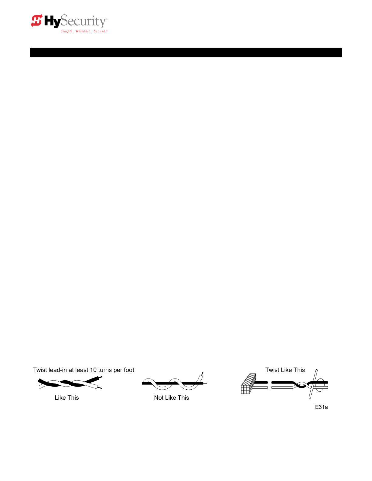
Detector Loop Installation Guide
Detector Basics
The vehicle detector passes a small current flow through the ―loop‖ which then becomes an inductive
coil. When a vehicle passes over a loop the detector senses the resultant drop in the inductance, and
actuates the detector output.
Loop Configurations
Configurations differ depending on the application. In parking applications with the StrongArm operator, a
loop may be as small as 3’ x 6’. In other applications, specifically if high bed trucks must be sensed, the
smallest loop should not be less than six feet square.
Rules to Follow for Security Gate Applications
1. The loop closest to the arm shall be centered directly under the barrier arm.
2. The shortest side of the loop shall be between four (3) and eight (8) feet in length. The longest side of
the loop shall be between six (6) and twenty (20) feet in length. For applications that need to span a
wide area, use several smaller loops. Do not exceed a maximum of 200 square feet of loop area to
only one detector.
3. In applications with multiple loops, keep each loop at least six feet apart. This avoids ―cross talk‖. It
is possible to have loops closer together by selecting different frequencies. An advantage of using
HySecurity model HY-5A detectors is that problematic ―cross talk‖ is not possible.
4. To avoid interference, keep loops at least two (2) inches above any reinforcing steel. Do not route
loop wires with, or in close proximity to, any other conductors, including other loop leads, unless
shielded lead-in cable is used. Never route high voltage circuits in PVC conduit near a loop.
5. Loop and lead-in wire should be one continuous piece. Avoid splices, if possible. If a splice is
necessary for any reason, ―pot‖ the splice in epoxy or use heat shrink to ensure that the quality of the
splice covering is the same as the original wire jacket.
6. Use only number 14, 16, or 18 gauge stranded wire with a direct burial jacket. Cross linked
polyethylene insulation types, such as, XLPE or XHHW, will last much longer and are less prone to
damage during installation than conventional insulation types. Preformed loops can be used before
road surfacing or under pavers.
7. Twist loose tails of lead-in wires tightly, approximately ten times per foot.
StrongArm Installation and Reference 35
Page 46

Detector Loop Installation Guide, continued
8. Follow this guide for the correct number of wire turns according to the perimeter size of the loop:
10 to 13 lf. = 5 turns 14 to 26 lf. = 4 turns 27 to 45 lf. = 3 turns 46 to 100 lf. = 2 turns
9. This guide is written from a design perspective, but installation workmanship practices are equally
important to insure proper operation and long loop life. The best way to insure a quality installation is
to employ a professional installer experienced with detector loops. A few important practices are: A.
The slot in the surface should be cut ¼‖ wide x 1 ½‖ deep. B. The corners of the cut must be at an
angle or core drilled to relieve stress on the wires. C. After the wire is installed, the slot must be
completely backfilled with a non-hardening sealer. Note that if the loop wires are able to move in the
slot after the sealer has set, the detector may give false calls.
Detector Logic
HySecurity Gate Operators recommends that vehicle detectors be used for free open and obstruction
sensing logic only. The exception is in parking applications with our StrongArm (HTG 320) barrier arm
operator where a reset detector may be also used to close the gate. In applications employing our
swing, vertical lift, or sliding gate operators, closing logic cannot be used.
Loop Diagnostics
The following tests cannot guarantee a functioning loop, but failure of either test means that the loop is
definitely suspect, even though it may still be functioning at the time.
Test #1:
Resistance of the loop and lead-in wire should not exceed 4.0 Ohms.
Test #2:
The resistance to earth, as measured with a 500V ―Megger‖, should be 100 Megohms or more. Loops
may function at 10 Megohms or less but will not be reliable (e.g. when the ground is wet from rainfall).
Low resistance indicates broken or moisture saturated insulation. This is common if inappropriate wire
insulation has been used.
See also Detector and Loop Fault Diagnostics on page 41 for additional tests that may be performed with
HySecurity HY-5A detector modules.
StrongArm Installation and Reference 36
Page 47

E95
StrongArm Installation and Reference 37
Page 48

Vehicle Detector Installation Options
The Smart Touch Controller provides a feature rich interface to four different vehicle detector inputs.
Standard box type 11 pin (24 Volt DC or 24 Volt AC) vehicle detectors may be connected in the
traditional manner, see page 38. HySecurity also offers a custom mini detector module that plugs
directly into the Smart Touch Control board. Not only is the field installation much faster, but there is also
a large performance benefit. The HySecurity HY-5A detector is controlled by the Smart Touch
microprocessor to achieve many benefits over common box type detectors*
a. Loop frequency is automatically set and monitored
by the Smart Touch Controller
b. Cross talk between multiple loops is impossible
c. The best operating frequency for each loop is
automatically chosen
d. Smart Touch can report the both loop frequency and
call strength on its LCD display
e. Smart Touch will report loop malfunctions and store
this data in its EEprom memory
f. Most detector or loop faults that could occur are
reported and displayed on the LCD display
There are four vehicle detector inputs available both on the main terminal strip and as direct plug in
modules. The vehicle detector inputs are for the following functions:
1. Free Exit Loop Detector – “ELD”
2. Outside Obstruction Loop Detector – “OOLD” (this is the outside reversing loop)
3. Inside Obstruction Loop Detector – “IOLD” (this is the inside reversing loop)
4. Reset Loop Detector – “RLD” (this is used to trigger a Barrier Arm gate closed)
*A combination of HY-5A detectors and standard box detectors is acceptable
It is not mandatory to use the inner or outer obstruction detector inputs for a barrier arm.
The obstruction detector inputs are primarily used for sliding and swing type security gates. The primary
loops for most barrier arm systems are for the Reset Loop Detector and the Free Exit Loop Detector.
StrongArm Installation and Reference 38
Page 49

I16
[or 1] OOLD detector function
1
0 = pause closing only, 1 = enable reversing to open
I17
[ir 1] IOLD detector function
1
0 = pause closing only, 1 = enable reversing to open
I18
[Cr 1] RLD -Reset detector function
0
0 = Reopen if tripped while closing, 1 = Pause only
I19
[Cb 0] RLD -Reset detector function
0
0 = One way, 1 = Bi-directional - disables ELD if tripped first
I20
[CP 0] RLD -Reset detector function
0
0 = Std. Close, 1 = Count opens & closes after equal reset
I21
[Eb 0] ELD –Exit detector function
0
0 = Off, 1 = Enable ELD back off auto close feature
HySecurity HY-5A Vehicle Detector Installation
1. Insert the locking end of each of two 1‖ long white plastic standoffs into the mounting holes on the
detector.
2. Plug the detector into the appropriate socket along the right side edge of the Smart Touch
Controller board for the detector function that is desired. Be careful to align the six detector pins
into the socket correctly, and then snap the standoffs into the holes on the right side of our control
enclosure.
3. Route the loop wires through the wire clips provided and connect the loop leads to the two
terminals directly on the detector. Tighten the terminal screws securely.
4. When the power is turned on, the detectors will immediately tune themselves.
5. Once enabled, if the detector module is unplugged, a communications alert [AL10] will be
triggered, then if the fault continues, [Err3] ―detector failed‖ is displayed. The operator will also
run as if the affected detector is triggered. The [Err3] can only be cleared by pressing the Reset
button, which electronically uninstalls the detector. See Detector & Loop Diagnostics on page 41.
6. The Smart Touch Controller automatically governs frequency selection of all Hy-5A detector
modules. This simplifies installation and guarantees that there is no cross talk between multiple
loops. The frequency can also be manually selected if needed, see the installer menu options.
7. Sensitivity is the only adjustment on the detector itself. Generally sensitivity does not need to be
increased unless the loop is large loop or there are multiple loops connected to one detector. Do
not exceed more than 200 sq/ft of loop area to one detector.
The rotary switch for sensitivity has eight settings, which are as follows:
0 = Low, 1 = Normal, 2 = Medium, 3 = High (0-3 with the boost feature*)
4 = Low, 5 = Normal, 6 = Medium, 7 = High (4-7 no boost feature*)
*Boost increases the sensitivity during a call and is very useful for maintaining continuous
detection when the signal may become weak, such as semi-trucks.
8. Vehicle detector functions are configurable in the Installer Menu as shown below.
Installer Menu Options Default Description
I18 [Cr__] Controls whether the reset loop stops only or reverses for a tailgating vehicle.
I19 [Cb__] Allows bi-directional use by disabling the free exit loop when a vehicle enters.
I20 [CP__] Adds an open input counting function that allows the arm to stay open until a 2nd car exits.
This is useful to not trap the 2nd vehicle if the open input has some kind of anti-passback function.
I21 [Eb__] Allows the free exit loop to generate a close command when cleared.
The outside and inside Obstruction Loop Detectors ―OOLD‖ or ―IOLD‖ are factory configured to fully reopen the gate. Each detector can individually be set so that when the gate is closing there is only a
pause if triggered. Set the menu items [ir__] and [or__] to 0 for pause only.
StrongArm Installation and Reference 39
Page 50

Standard 11 Pin Box Type Vehicle Detector Installation
1. If standard 11 pin vehicle detectors are to be used, snap up to three sockets onto the aluminum
DIN mounting rail, with the key in the center hole facing to the left. Mount on the shelf near the
top of the operator and wire as shown below.
2. Both 24 Volts AC or DC are available, so either detector voltage may be used. (24 VAC is not
available if the operator is a battery type) 24 VAC is available at the spade terminals on the lower
left corner of our power supply (marked ACC). 24 VDC is available from the Common Buss and
the +24 V spade terminals next to the common Buss.
3. Connect 24 Volt power to the detector. Polarity does not matter if the detector is a 24 AC model.
If a DC detector is used, pin #1 is (+) on a DC detector and pin #2 is ( - ).
4. Connect the output pin #6 to the common Buss on the power supply and the output pin #5 to one
of the four detector inputs (depending upon the detector function required) on the Smart Touch
Controller terminal strip.
5. If multiple detectors are used, join the wires from socket to socket rather than run each to the
same location separately. The only wires that are separate is the output wire to the Smart Touch
Controller and the loop input wires.
6. Always keep the loop wires well twisted at all places beyond the area of the loop. The lead in
portion sealed in a saw cut does not need to be twisted so long as the wires are encapsulated in
loop sealant and cannot move.
StrongArm Installation and Reference 40
Page 51

Loop abnormal freq change alert
ALE7
2 chirps/sec every 15 seconds
Loop shorted to ground alert
ALE8
2 chirps/sec every 15 seconds
Loop disconnected alert
ALE9
2 chirps/sec every 15 seconds
Loop detector active >5 minutes
AL12
2 chirps/sec every 15 seconds
Loop detector comm. alert
AL10
2 chirps/sec every 15 seconds
Loop detector function alert
AL11
2 chirps/sec every 15 seconds
Loop detector failed
Err3
3 chirps/sec once per minute
I24
[ELd0] Test factory ELD
0
0=Run, 1=show freq, 2=show call level 0-7, 3= set Freq 1-4
I25
[iLd0] Test factory IOLD
0
0=Run, 1=show freq, 2=show call level 0-7, 3= set Freq 1-4
I26
[oLd0] Test factory OOLD
0
0=Run, 1=show freq, 2=show call level 0-7, 3= set Freq 1-4
I27
[rLd0] Test factory RLD
0
0=Run, 1=show freq, 2=show call level 0-7, 3= set Freq 1-4
Detector & Loop Fault Diagnostics
If HySecurity HY-5A mini detector modules are used, the Smart Touch Controller has ability to store and
report detector and loop fault information for performance diagnostics. If The Smart Touch Controller
senses a loop or detector problem, the LCD display will flash the abbreviation for the affected detector
(ELd – ioLd – ooLd – rLd) then it will flash the appropriate Alert Code [ALE_] to disclose the nature of the
problem and the buzzer will chirp.
Even if the loop problem self heals, historical data about detector/loop performance and a log of Alerts,
Faults and Errors can be retrieved from the Smart Touch Controller by downloading from the RS232
communications port. This requires optional HySecurity software and cables, and a PC computer or a
PDA using the Palm OS, in order to read this data.
Frequency:
Knowing the exact frequency of a loop can be useful as a diagnostic tool and verifying that the loop
frequency is stable is also very valuable information. To view the actual loop frequency of a specific
vehicle detector, go to the setting for that detector, then change the selection to a flashing 1 and then
press the Select button. The display will flash between [F_xx] which are the high digits, then the low
digits of the loop frequency counter. For example: [F_05] + [3413] would represent a frequency of
53,413 Hertz. The highest digit will probably be only a single digit because loop frequency is usually a
five-digit number, between 20,000 to 80,000 Hertz.
Changing the Loop Frequency:
HY-5A detectors can never crosstalk, but if for any reason, you want to manually change the loop
frequency, change the menu selection to a flashing 4 and then press the Select button. Each detector
has a choice of four frequencies. To exit, press the Menu button and the controller will perform a reset
and tune to the new frequency setting.
Call Strength Level:
Knowing the strength level of a detector call is valuable because it provides information about how well
the loop is actually ―seeing‖ a specific vehicle. For example, it may be useful to check to see if the loop
is easily detecting the middle of a high bed semi-truck. The strength of a detector call can be displayed
in real time, on a scale of 1-7. As indicated in the table below, when a detector’s menu setting is set to 2,
and the Select button is pressed, the LCD display will read [LE_x]. If the call strength is level 4 or
less, consider increasing the sensitivity level, by adjusting the rotary switch on the HY-5A detector.
Installer Menu Options Default Description
Acronyms: Free Exit Loop = ELd, Outside Obstruction Loop = ooLd, Inside Obstruction Loop = IoLd
Reset Loop Detector = rLd (this is for barrier arm gates only)
StrongArm Installation and Reference 41
Page 52

24 Hr, 7 Day Timer Option
This is an option you can order from HySecurity. The timer generates an open command which will hold the gate
open until it is released. Instructions on how to use and program it accompany the timer.
To connect the optional timer to the Smart Touch Controller, use the following schematic:
Connect the Timer Power Pin 1 to 24V (+)
Connect the Timer Power Pin 2 to COM
Connect the Timer Com Pin 3 to COM
Connect Timer NO Pin 4 to #7, Time Clock Open
Connecting a Radio Receiver for Remote Open
Mount a commercial style 24-Volt radio receiver (external antenna type) on the inside of the operator,
below the electrical box. Knock out the smallest hole in the lower right corner of the electrical box and
route the wires to the area marked Radio Options. Only three wire connections are needed because the
24-Volt supply and the radio output share a wire. Being certain to observe polarity, crimp the black radio
power wire together with one of the radio output wires into a .25‖ spade connector and connect to the
COM terminal. Connect the red wire to the +24V terminal and connect the other radio output contact wire
to the spade marked OPEN. Note that this terminal is the same as the #4 input terminal labeled Edge
Sensor on the main control board.
Mount an external antenna onto the top of a fixed post of the fence near the operator.
Connect the antenna into the socket on the radio receiver.
Set the DIP switches in the receiver to match the same code used in the transmitter.
If there is also to be an edge sensor transmitter to reverse the gate, be certain to use a two channel
commercial receiver. Remember that each transmitter and receiver must have their codes set the same
or they will not function.
StrongArm Installation and Reference 42
Page 53

Troubleshooting Guide, StrongArm (HTG 320) Gate Operators
Important Note:
If the manual bypass valve is open, the electric motor will run, but nothing will move. See the drawing on
page 10 to locate the bypass valve. To close the valve, twist to allow the knob to re-engage.
Electrical Problems in General:
The Smart Touch Controller reports system malfunctions on its LCD display and the buzzer will emit a
series of chirps at defined intervals. Review the matrix of Alerts, Faults and Errors listed on the next
page. To disclose the status of all inputs on the terminal strip, the LED tact button must be pushed. This
button is in the upper left corner near the Stop input.
Specific Types of Problems:
"I pushed the open and close buttons, but nothing runs."
1. Verify that the line voltage is present and matches the operator voltage + 10%.
2. Verify that control voltage is present at the power supply Common and 24VDC terminals. It may be
necessary to reset the circuit breaker (black button) on the transformer.
3. Verify a jumper wire joins Common to Stop, if an external stop button is not used.
4. Verify there are no Faults or Errors reported on the LCD display. See table on next page.
5. If the gate is in the open position, and an open input is still active, a close input cannot close the
gate until the open input is cleared. Verify the input status by pressing the LED tact button.
6. If the motor contactor chatters, voltage drop due to undersized wires is the likely cause. Check
Appendix 9 for the maximum allowable length of wiring runs vs. wire size.
"Motor is running, but nothing is moving."
1. Check the manual bypass valve. Close it if found open. See note at top of this page.
2. If the power is three-phase and the electric motor is running clockwise reverse any two of the three
lines.
3. Check the fluid level in the reservoir. See maintenance instructions.
4. If the arm is closed and will not open, assist the arm by lifting it manually, if the arm moves with
help, the open brake valve may be set too tight or pressure relief valve set too low. Alternately,
there may not be sufficient counterweight. See page 11 for adjustments.
5. If the arm is open and will not close, check the close brake valve setting. See page 11.
"The arm tries to close when commanded to open."
1. Verify that the electrical coil to the hydraulic directional valve is connected.
2. Review information below pertaining to the directional valve.
"The arm bounces at the end of travel."
1. The brake valves and/or limit switches need adjustment. See page 13 for this procedure.
DIRECTIONAL VALVE: Our operators employ a two position, single solenoid directional valve. When
24-volt DC power is applied, the flow is directed to open the gate. In its normal spring loaded relaxed
position the flow is directed to close the gate. If a malfunction should occur, it would most likely cause the
gate to only move in the close direction. The directional valve is totally maintenance free.
To troubleshoot, first verify that 24 volts is being applied to the valve coil when an open command is
given. Next, verify that the valve coil is functioning by removing its retaining nut and holding the coil
slightly loose to verify that it is magnetized when the controls are activated to open the gate. If the
problem persists, exchange the valve and change the hydraulic oil so that any debris in the oil would be
removed.
StrongArm Installation and Reference 43
Page 54

Error, Fault, or Alert Status
LCD Display
Buzzer Chirp Sequence
Cannot respond due to tripped sensor
or in Entrapment mode
Entr
2 chirps/sec every 2 seconds while control
input is active
Safety Mode Alert
SAFE
2 chirps once when in Safety Mode
Low 24V Control Voltage Alert
Lo24 (ac or dc)
N/A (display flashes 1 sec every 5 seconds)
Critical Low 24V supply power
BadP (ac or dc)
N/A Display steady – controls disabled
Dead 24V Battery Alert –DC only
bat - dEAd
3 chirps upon any operating command
Gate forced open Alert
ALE1
2 pulses/sec for 30 seconds
Gate drift closed Alert
ALE2
2 pulses/sec for 10 seconds
Motor thermal overload Alert
ALE4
2 chirps/sec every 15 seconds
Limit not released in 10 seconds
ALE6
2 chirps/sec every 15 seconds
Loop abnormal freq change alert
ALE7
2 chirps/sec every 15 seconds
Loop shorted to ground alert
ALE8
2 chirps/sec every 15 seconds
Loop disconnected alert
ALE9
2 chirps/sec every 15 seconds
Loop detector comm. alert
AL10
2 chirps/sec every 15 seconds
Loop detector function alert
AL11
2 chirps/sec every 15 seconds
Loop detector active >5 minutes
AL12
2 chirps/sec every 15 seconds
General I2C comm. buss failure
AL16
2 chirps/sec every 15 seconds
Bad 3V coin battery
AL17
2 chirps/sec every 15 seconds
Lock Interlock (Input #22) Blocks Open
AL17
2 chirps/sec every 15 seconds
Maximum run Fault
FAL1
1 chirp once every 15 seconds
Photo eye Fault (supervised)
FAL2
2 chirps/sec once per minute
Critical AC sag – bad supply wire
FAL3
2 chirps/sec once per minute
Directional motion Error
Err1
3 chirps/sec once per minute
Disconnected IES Error
Err2
3 chirps/sec once per minute
Loop detector failed
Err3
3 chirps/sec once per minute
Master/slave RS485 comm. Error
Err4
3 chirps/sec once per minute
EEPROM Data Error (factory)
Err7
3 chirps/sec once per minute
EEPROM Data Error (installer)
Err8
3 chirps/sec once per minute
EEPROM Data Error (user menu)
Err9
3 chirps/sec once per minute
Program Data Error
FAiL
3 chirps/sec once per minute
Troubleshooting
The Smart Touch Controller system includes many self diagnostic capabilities. The LCD will display specific
messages and the Audio Alert buzzer will sound distinctive chirps. Any Alerts, Faults or Errors are also logged into
a memory and stamped with a time and date. For diagnostic purposes, these messages can be retrieved with
optional WinLogger software available from HySecurity Gate.
The following chart is a listing of codes that would appear on the LCD display if problems are detected by
the Smart Touch Controller.
The green LED (near terminal #24 on Classic Controllers or near the “coin” battery on New Generation
Controllers) is the heartbeat of the processor. This LED should always blink brightly to indicate normal
operation.
GATE SPEED: The speed in which a hydraulic operator moves a gate is determined by the size of the pump and
the size of the actuator components. Just like a gear box, this speed is not adjustable. Attempting to slow a gate by
changing any valve setting will cause a great deal of inefficiency and heat. If the speed of a gate must be changed,
contact your HySecurity distributor. Extremely cold weather is unlikely to seriously affect the speed of the gate,
because HySecurity employs a special grade of hydraulic oil that we call UNIFLOW oil, which maintains a very
linear viscosity over a broad range of temperatures. Because of this high quality oil and other design
considerations, we rate our operators for service in ambient temperatures of –40F degrees to 130F degrees. If the
speed of your operator has been affected by cold weather, verify that the gate hardware s not impaired by ice and
verify that the reservoir it is filled with UNIFLOW oil. In severe conditions, consider adding a heater.
StrongArm Installation and Reference 44
Page 55

General Maintenance
Hydraulic System
Fluid Level: Under normal conditions, hydraulic systems do not consume oil. Before adding any oil,
check the system thoroughly for leaks. Remove the bright metal plug in the tank, fill to plug level, then
replace plug. We recommend our Uniflow hydraulic oil; part number H004 1.0, which is sold in one-gallon
containers by our distributors. Never use brake fluid. It will severely damage the entire hydraulic
system. Use of any oil other than Uniflow oil may void the operator warranty.
Look for leaks: Occasionally there may be slight seeping at the fittings after some usage. Tightening of
the fittings will usually correct the problem. If the leaking persists, replace "O" rings, fittings or hoses, if
required. No further leaks should occur.
Oil Change: A hydraulic system does not foul its oil, unlike a gas engine, so oil changes do not need to
be frequent. Oil breakdown caused by heat is the main concern. If the unit is subjected to high use,
especially in a warm climate, change the oil more frequently. In general, we recommend draining the
reservoir and replacing the oil at five-year intervals.
To change the hydraulic oil, remove the reservoir from the pump unit and completely, empty it and wipe
the reservoir clean and clean the derby screen before re-assembling. Refill with new Uniflow hydraulic
oil. Slowly pour the oil into the tank until the oil is within one inch of the filler port. Replace the plug and
wipe up any spilled oil. If any oil is allowed to remain, it will dry to a very sticky and messy consistency.
Mechanical Maintenance
Before servicing, turn off power disconnect switch
Depending upon duty cycles, use a grease gun to apply a lithium-based grease into the crank arm zerk
fitting on six month to one year intervals. The main shaft bearings should be greased annually.
Electrical Controls
No routine maintenance is needed for the electrical system or controls. If the environment is very sandy
or dusty, or has many insects be certain to seal all holes in the electrical enclosure. Blow the dust out of
the electric panel with compressed air. A qualified technician may troubleshoot with the aid of the
troubleshooting guide in this appendix. If it is necessary to call a distributor for assistance, be sure to
have your model and serial number ready. Other helpful information would include the name of the job,
approximate date of installation, and the service record of the operator, especially any work that has
been done recently.
How to Adjust the Pressure Relief Valve: To check your relief valve setting, first loosen a limit switch
cam so that the operator will not shut off in one direction. Run the operator to either open or closed (the
gate will not move with the hose disconnected. The relief valve is found on the rear of the hydraulic
power unit. It has an adjusting head and lock nut. To adjust, loosen the lock nut and screw the threaded
bolt clockwise for increased pressure, counterclockwise to decrease pressure.
MODEL FACTORY RELIEF SETTING
StrongArm (HTG 320-2) 700 PSI
StrongArm (HTG 320-3, -6, -8) 1000 PSI
StrongArm Installation and Reference 45
Before servicing, turn off power disconnect switch
Page 56

1 3 6 12
60
Anchor bolts
Check for tightness
*2 X
Limit Switches
Check for adjustment
*3 X
Fluid level
Check for loss of fluid
*4 X
Hydraulic fluid
Drain and replace fluid
*5
X
Brake Valves
Check for adjustment
*6 X
Clock Battery
Replace
*7
X
Crank Arm Zerk
Lubricate with Grease
X
Motor Brushes (DC Only)
Replace
*8
x
Maintenance Schedule
Barrier Gate Operator Maintenance Schedule
Name of part What to do Check at these recommended monthly intervals
Special Notes:
*1. Damage to the barrier arm is usually the result of vehicular contact with the arm. Contact with the
arm can also cause the crankshaft bearings to become loose or cracked if the contact force is great
enough. This is not a warranty Issue.
*2. Confirm that the anchor bolts are tight and that the chassis hadn’t shifted, which can also happen with
vehicle contact to the operator.
*3. Check to see that the limit cams are tight and that they contact the limit switches enough to trip them
but not crushing the limit switches.
*4. The oil level should remain approximately one inch below the filler hole. See maintenance instructions
for oil filling. Loss of fluid is not normal and indicates a leak that must be located and repaired. The cap
for the filler hole is a breather and needs only to be finger tight. Use ―Uniflow‖ fluid, part # MX000970, if
additional fluid is required.
*5. To drain the hydraulic oil, leave the arm in the closed position, and disconnect the hydraulic hose
where it connects to the top of the hydraulic cylinder. Place the disconnected hose into a waste
receptacle and start the gate in the open direction. All of the oil will drain within 15 seconds. Stop the
pump immediately, when the flow ceases. Re-connect the loose hose. Refill with new UNIFLOW
hydraulic oil available from the factory, or use a substitute, if performance in cold weather is not a
question.
*6. Confirm that the brake valves are stopping the arm properly, and adjust if needed.
*7. Replace battery with DL 2025 / DL 2032 or CR 2025 / CR2032.
*8 DC Operators use DC motors with carbon brushes which wear in normal operation. Worn brushes
can damage the DC motor. Under severe conditions HySecurity recommends that brushes be checked
after 2 years and the replacement interval be adjusted as necessary.
StrongArm Installation and Reference 46
Page 57

IMPORTANT SPECIAL NOTES REGARDING
D.C. POWERED GATE OPERATORS
The on/off switch on the electric control panel of the drive unit does not disable all DC power to the
operator, even if the AC power has been disabled at its source. The large rotary switch in the DC power
supply enclosure must be actuated off to insure disconnect of all DC power to the drive unit.
The disconnect in the power supply must be off if the AC source power will be absent for more than one
week. This avoids slowly discharging the batteries into the battery charger. Batteries will self-discharge
and therefore the DC power supply must not be stored for a period longer than 6 months without
recharging the batteries.
Batteries contain sulfuric acid. If batteries are dropped or damaged, be cautious not to get acid in the
eyes, on skin, or on clothing and replace the batteries are immediately.
Be certain to observe polarity when connecting the batteries, or adding accessories. Reversed polarity
may result in a non-functional operator or possibly damage a component. Red is (+) positive, and black
is (-) negative.
Since the electrical current under load is very high, be certain that the minimum conductor size, specified
in the installation instructions, is used for the connection between the battery pack and the operator. If
the battery pack is more than 20 feet from the operator, use a larger wire size, according to the distance
between the operator and the batteries.
If shorted, batteries will generate a very high current. Observe special care when connecting the cables
to the batteries that the polarity is correct. The batteries are connected in a series circuit: join the positive
(+) terminal from one battery to the negative (-) terminal of the next battery.
Since this operator is intended to run on batteries, control of the load is important. Easier moving gates
will drain less energy from the battery, preserving capacity for more cycles during a power failure.
HySecurity uses a permanently sealed type battery, which needs no maintenance over its life span. A
low voltage-sensing circuit protects the batteries from damage which could be caused by over-discharge.
The charger automatically regulates its output to allow high output when the battery is partially
discharged. The output will automatically be reduced to zero as the batteries become fully charged.
Batteries have a finite life. As the batteries age they will lose some of their capacity to store energy. If the
total amount of back up capacity is critical, plan to replace the batteries after 5 years of use. Properly
dispose of or recycle used batteries.
Batteries are rated to perform to capacity at a temperature of 77 degrees Fahrenheit. Below 77 degrees,
the "amp hour" capacity is temporarily reduced. For example, at freezing, the capacity is 75%, at 10
degrees Fahrenheit, the capacity is 50%. HySecurity insulates the battery pack to guard against this loss.
Do not remove any insulation or the performance of the system may be adversely affected.
Batteries can be damaged by excessive heat, which may shorten their life span. Therefore, do not paint
the battery enclosure a dark color that could cause it to absorb a lot of heat from sunlight.
DC Motors contain carbon brushes which wear over time and must be replaced. Failure to replace the
brushes will result in damage to the DC motor. Brushes should be replaced every 5 years, or sooner in
high use and/or severe duty installations.
StrongArm Installation and Reference 47
Page 58

Wiring and Control Configuration for DC Operators
If this installation is a 24-Volt DC battery type gate operator, there are a few additional steps that must be
completed before the system can be functional. Review the installation instructions on page 10 and the
connection diagram on page 50. Be certain the DC power disconnect switch is turned off before
making any connections.
1. Connect the heavy gage wires between the battery enclosure and the gate operator as follows:
Be certain to observe polarity carefully!
a. From the battery enclosure the (+) lead connects to the lug on the large rotary power
disconnect switch. The (-) lead connects to the lug on the circuit breaker. At the gate
operator the (+) lead connects directly to the lug on the top of the DC electric motor. The
(-) lead connects to the bottom lug on the contactor mounted alongside the DC motor. All
lug connections must be tightened very securely since they pass high current to the gate
operator.
2. Connect two separate 14-gage circuits between the battery enclosure and the gate operator.
One circuit provides the 24 VDC to the gate operator controls and the second circuit is required
so that the Smart Touch Controller knows that the battery charger is operating normally on AC
power. Be certain to observe polarity carefully!
a. Connect four wires to the terminal strip in the battery supply labeled: (+)24, (-)24, COM,
#21. The 24 Volt (+) and (-) terminals connect to the red (+) and black (-) wires at the
on/off power switch in the gate operator.
b. The COM and #21 terminals connect to the Common Buss and to terminal #21 (Charger
AC power loss) on the Smart Touch Controller.
3. The Smart Touch Controller User Menu (U4) provides four optional system configurations for 24Volt DC battery type gate operators. Since this is an uninterruptible power supply system, the
installer must decide, depending upon customer preference, what is to happen when the AC line
power fails. The User Relays will operate to less than 18VDC. There are four functional choices
provided in the User Menu, item [AP_].
Setting 0 (Type A): The operator functions normally until the batteries drop to 20 Volts, then auto
open and lock until the battery voltage recovers to 23.5 Volts. The gate can still be manually
closed only by a Close Pushbutton or an Emergency Close input and will then re-open by any
open command until the battery voltage drops to 17 Volts at which time the gate is absolutely
locked open, unless moved manually.
Setting 1 (Type B): The operator functions normally until the batteries drop to 20 Volts, then auto
close and lock closed until battery voltage recovers to 23.5 Volts. The gate can only be opened
by a special combination of a Stop Pushbutton input, then within 1 second, an Open Pushbutton
input. The Fire Department open input can open the gate without the special PBS enabling preinput. The gate can be re-closed only by Close Pushbutton and the Emergency Close inputs.
When the battery voltage drops to 17 Volts, the gate completes its final cycle and stays in the full
open or full closed position, depending upon which cycle was last.
Setting 2 (Type C): The operator automatically opens five seconds after loss of AC power and
locks open, until AC power is restored. The gate can still be manually closed only by a Close
Pushbutton or an Emergency Close input and will then re-open by any open command until the
battery voltage drops to 17 Volts at which time the gate is absolutely locked open.
Setting 3 (Type D): Same as type C, except the operator initially does nothing after loss of AC
power, but then locks open after the next open command of any type.
StrongArm Installation and Reference 48
Page 59

D.C. POWER BATTERY PACK
2 BATTERY, 110AH; 30‖H X 30‖W X 12‖D
Power supply wiring to drive unit:
6 conductors required
2 ea. 14 gauge minimum for AC power loss indication
2 ea. 14 gauge minimum for control panel
2 ea. Heavy gauge for motor
6 gauge minimum up to and including 1 hp models.
Add two 14 gauge minimum if drive unit heater is supplied.
StrongArm Installation and Reference 49
Page 60

24V 110A.H. BATTERY POWER
SUPPLY FOR DC OPERATORS
Connect six wires to the gate operator as shown.
Four 14 gauge wires to the Control Circuit
Connect from lug
Terminals to DC Motor
Two 6 gauge minimum for 1 hp
Or
Two 2 gauge minimum through 2 hp
Install batteries as shown observing polarity
Always observe polarity carefully.
Always connect red wires to (+) and black wires to (-) except
for the wires connecting the batteries.
StrongArm Installation and Reference 50
Page 61

Wire Size Schedules
For 1/2-hp through 5-hp motors
Supplying a gate operator with the right electrical service is crucial to the way the performance of the
operator the life of its electrical components. If the wire size used is too small, the voltage loss,
especially during motor starting, will prevent the motor from attaining its rated horsepower. The percent
of horsepower lost is far greater than the percentage of the voltage loss. A voltage loss could also cause
the control components to chatter while the motor is starting, substantially reducing their life due to the
resultant arcing. There is no way to restore the lost performance resulting from undersized wires, except
to replace them; therefore it is much more economical to choose a sufficient wire size at the initial
installation.
The tables on the following page are based on copper wire and allow for a 5% voltage drop. The
ampere values shown are the service factor ampere rating (maximum full load at continuous duty) of the
motor.
Always connect electrical power and ground the operator in accordance with the National Electrical
Code, articles 430 and 250 plus other local codes that may apply.
The maximum distance shown is from the gate operator to the power source; assuming that source
power is from a panel box with adequate capacity to support the addition of this motor load. The values
are for one operator, with no other loads applied to the branch circuit. Avoid placing more than one gate
operator to a circuit, but if you must be certain to reduce the maximum allowed distance by half.
Low Voltage Control Wiring:
The Smart Touch controller has very sensitive control inputs so the wire size of the control wiring is not a
significant issue. The following is a chart of maximum distances for the controls:
Wire Size Maximum Distance
18 ga 7.0 miles
20 ga 3.5 miles
22 ga 2.7 miles
24 ga 2.0 miles
26 ga 1.0 mile
28 ga 3700 feet
StrongArm Installation and Reference 51
Page 62

StrongArm Installation and Reference 52
Page 63

Parts Breakout
StrongArm Installation and Reference 53
Page 64

Parts Breakout
StrongArm Installation and Reference 54
Page 65

1-2 MX000321 1EA
1-3 MX000320 1EA
1-5 MX000965 1EA
1-6 MX001092 1EA
3-1 MX000658 1EA
3-2 MX000172 1EA
3-3 MX000184 1EA
3-5 MX000231 1EA
3-6 MX000226 1EA
3-7 MX000233 1EA
3-8 MX000229 1EA
3-9 MX000234 1EA
3-10 MX000230 1EA
3-11 MX001153 1EA
3-12 MX000171 1EA
3-13 MX000199 1EA
3-16 MX000146 1EA
3-18 MX000086 1EA
3-20 MX000101 1EA
3-21 MX000100 1EA
3-22 MX000102 1EA
3-23 MX000103 1EA
3-24 MX000236 1EA
3-25 MX000139 1EA
3-26 MX000659 1EA
Parts Breakout – AC Pumps
StrongArm Installation and Reference 55
Page 66

MX000234
HVABY 000 CRT
Parts Breakout – DC Pumps
StrongArm Installation and Reference 56
Page 67

3-1 MX000077 1EA
3-3 MX000228 2EA
3-18 MX000086 KIT
4-1 MX000312 2EA
4-2 MX000601 1EA
4-3 MX000601 1EA
4-4 MX000579 1EA
4-5 MX000306 2EA
4-6 MX001100 1EA
Parts Breakout
StrongArm Installation and Reference 57
Page 68

Item # Qty.
3-5 MX000231 1 each
3-7 MX000233 1 each
3-8 MX000299 1 each
3-9 MX000234 1 each
3-10 MX000230 1 each
3-11 MX000226 1 each
3-12 MX000226 1 each
3-13 MX000190 1 each
3-14 MX000146 1 each
Parts Breakout
StrongArm Installation and Reference 58
Page 69

Parts Breakout – DC Power Supply
StrongArm Installation and Reference 59
Page 70

Smart Touch Controller Connections
StrongArm Installation and Reference 60
Page 71

StrongArm Brake Valve Adjustment Procedure
StrongArm Installation and Reference 61
Page 72

StrongArm Installation and Reference 62
Page 73

Limited Warranty
StrongArm Installation and Reference 63
Page 74

StrongArm Installation and Reference 64
 Loading...