

Page 1
Cellular Intercom 4G
FAAC International Inc.
Headquarter & East Coast Operations
3160 Murrell Rd
Rockledge, FL 32955
Tel. 800 221 8278
www.faacusa.com
FAAC International Inc.
West Coast Operations
357 South Acacia Avenue
Fullerton, CA 92831
Preferred!
DO NOT GIVE TO HOME OWNER.
FOR PROFESSIONAL USE ONLY
Page 2

2
TABLE OF CONTENTS
Really important things you need to know
A look around the product
Overview of inside
Pedestal Installation
Power Module in detail
Cellular module in detail
Wiring relays
Keypad/prox module in detail
Connecting slave devices
Inserting the SIM
Powering up and LEDS
Installing the programmer APP for the first time
Programming a brand new install
Programming an existing install
Programming main steps
Additional Features
Keypad codes
Prox cards (optional models only)
Auto opening/closing
App control of gates
Do not disturb
After hours calling
Programming codes
Ringing times
Volumes
Information
Relay times
Complete list of parameters
Troubleshooting
3
4
4
5
6
6
7
7
8
8
9
9
11
11
12
15
16
17
20
21
21
22
22
23
23
24
25
25
28
Page 3
3
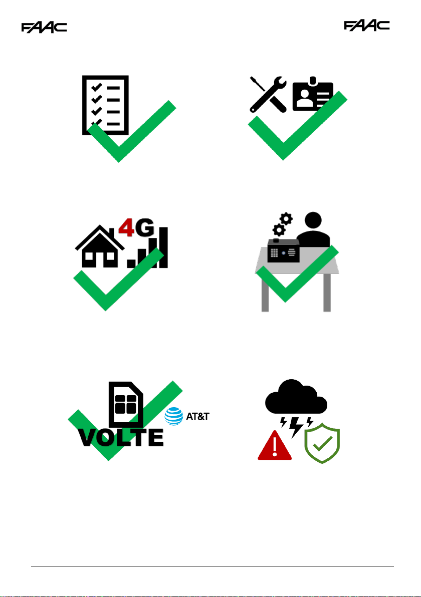
Really Important things you Need to Know..
Please read this entire manual before
installing this product.
To be installed by certified and qualified
personnel / gate automation dealer only.
Not for DIY install!
Ensure there is good At&T or T-Mobile 4G
signal at the gate/door of the install site
BEFORE installing this product. (This unit will
also fall back to 3G service in some locations
depending on network).
Set up on a bench in workshop BEFORE
going to site. Program the unit in the comfort
of your work bench and call technical
support should you have questions.
This product requires a SIM card from either
At&T or T-Mobile, however T-Mobile may not
have matching band coverage in your area!
The SIM should be a voice and text plan.
Do not use a DATA only SIM.
Ensure your SIM has VOLTE (HD Voice calling
service is enabled).
Manufacturer warranty does NOT cover
lighting / storm damage. You MUST fit
external surge protection and lightning rod in
order to maintain warranty on this product.
Evidence of surge protection will be
requested on generation of RGA numbers.
5
Preferred!
1
2
3
4
6
Page 4
4
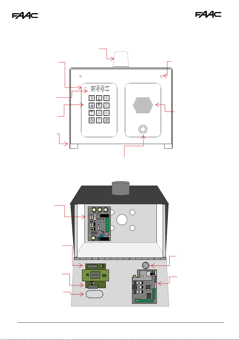
Now lets have a look around the product…
Overview of Inside…
Call button
Push button
Speaker grill
Cellular PCB
Optional
Prox Coil
Optional
Keypad
module
Optional Keypad
Optional
Prox reader
module
Surge &
Power
Conditionin
g Module
Hinged front
door
Microphone
Built in antenna
Security screw
access
Optional
Prox badge
reader
Page 5
5
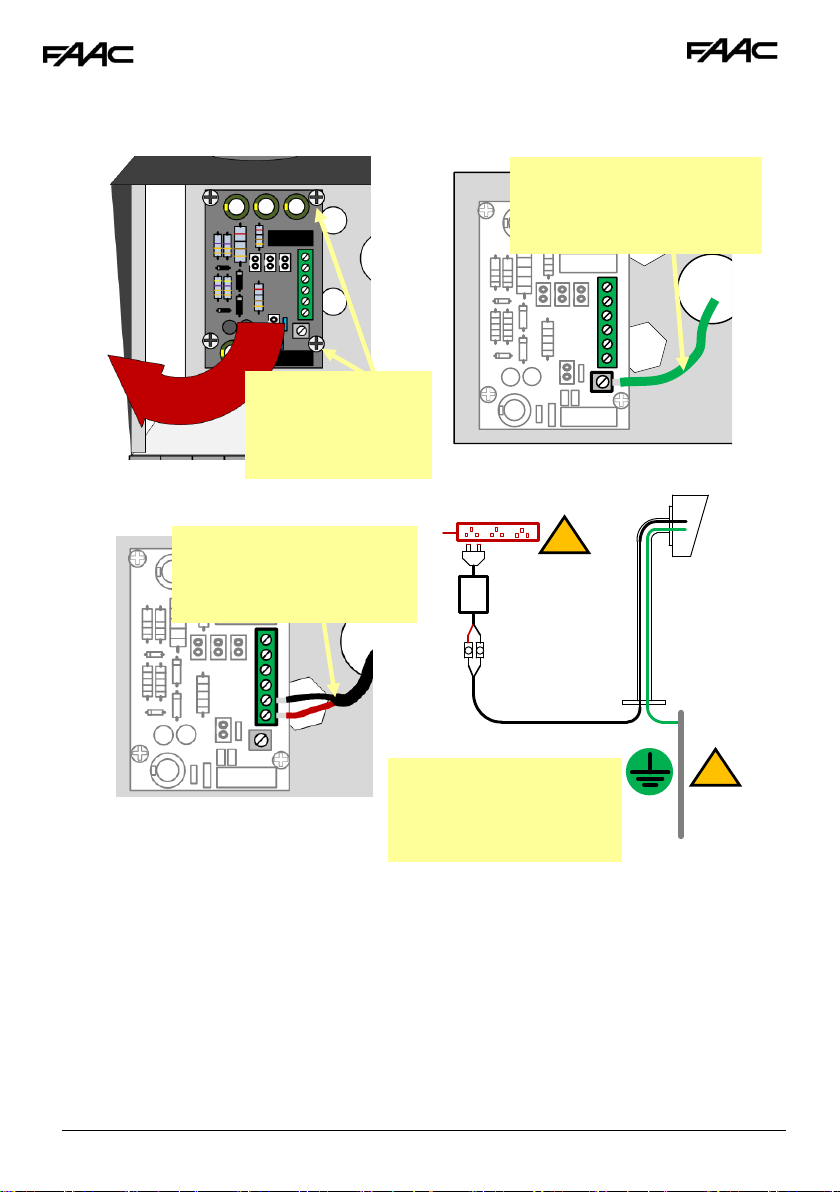
Pedestal Installation
!
!
3
Use minimum 16 gauge wire
from the 24v dc adaptor
provided to the terminals
shown.
1
After fitting the box to the
gooseneck, re-fit the module
and connect a 14 gauge
earth wire to the earth
2
Earth Rod
(close as
possible)
Maintain manufacturer’s
warranty by adhering to the
guidelines shown. Use 110v
surge protected supply.
Surge protected 110v
4
24v dc PSU
16 gauge
30 feet MAX
Call box
Remove 4 screws
and remove power
conditioning module
(if needed)
Page 6
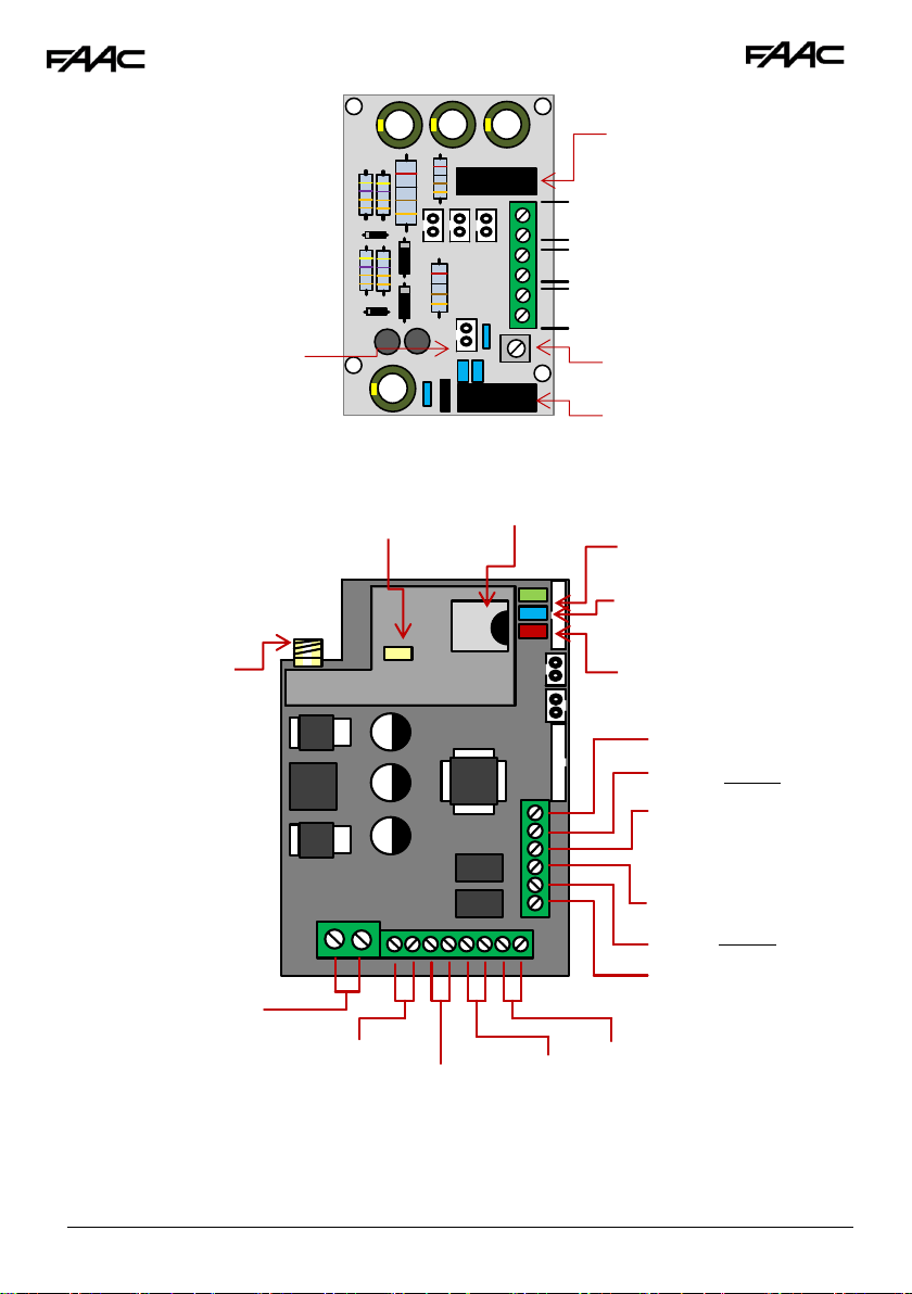
6
Relay 2
24vdc out
-
+ + -
+
-
Solar or 12v DC IN
24vdc IN (Do NOT use 12v here)
500mA quick blow
output fuse
Optional Battery
Connection leads
3Ah 12v dc max
Power
Module
in
Detail…
Earth Rod
Connection
Gate Position
Limit switch
(optional)
1A quick blow
input fuse
Exit Button
To Call
Button
12v dc 100mA
(backlighting)
24v dc IN
(pre-wired)
CPU Status
Signal Status
Power
Cellular
Module in
Detail…
SIM holder
Modem Status
Antenna
connection
Relay 1
N/O
COM
N/C
N/O
COM
N/C
Page 7
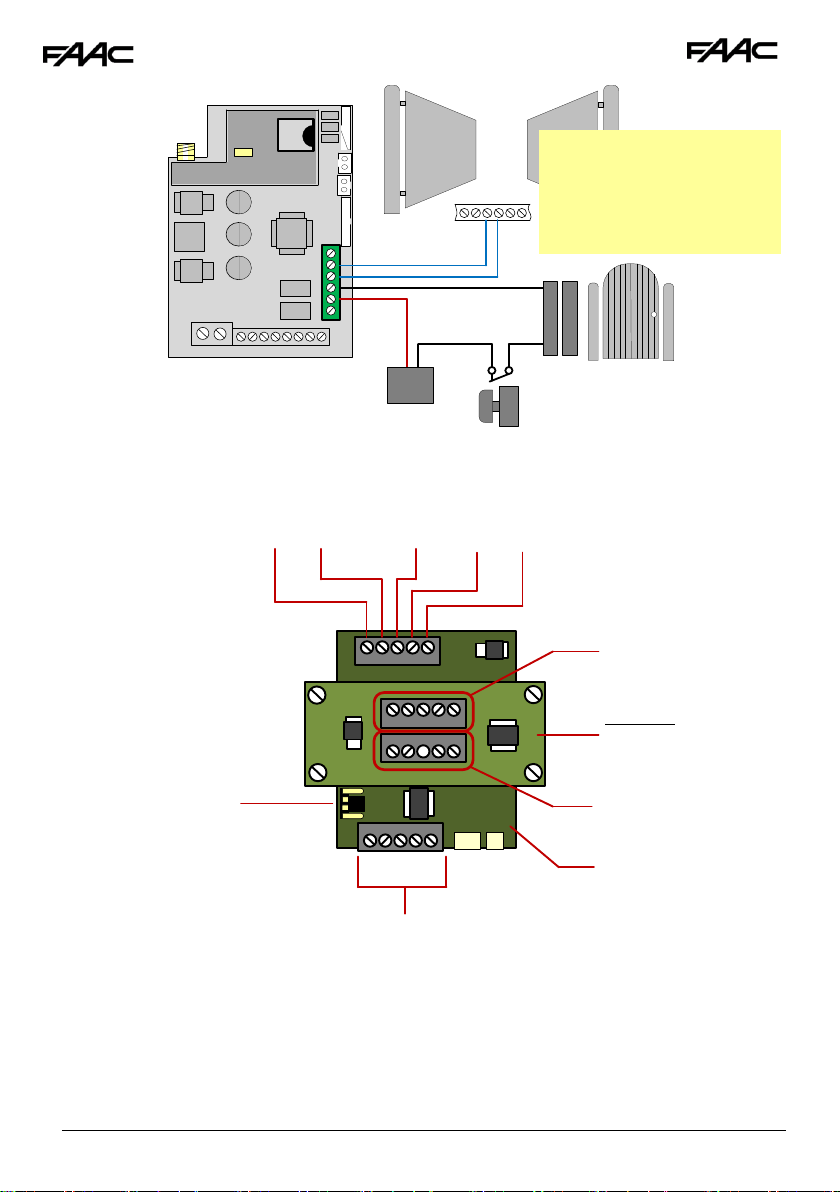
7
1
2
Slave IN connections
Slave IN
Slave OUT
3
Optional
PROX
module
Baud jumper (remove
for older intercoms)
Keypad
Module
Keypad /
PROX
Modules in
Detail…
Slave OUT connections
Wiring
Relays
Electric Gates
24v out
GND
Note: The manufacturer is not
responsible for wiring to third
party devices. Please consult
an experienced security
installer.
Pedestrian
gates or door
Magnetic
lock
Exit button
Separate lock Power
supply (not supplied)
Start
Common
Page 8
8
1 2 3 24v
OUT
IN
OUT
IN
OUT
IN
1 2 3 24v
OUT
IN
1 2 3 24v
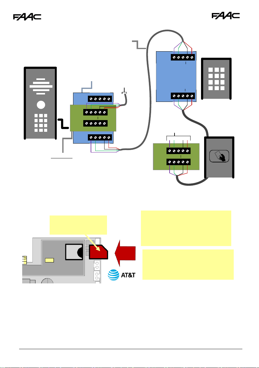
1 2 3 24v
Inserting the SIM card
WARNING
Ensure power is OFF. Do not hot
insert or remove while power on.
Preferred!
To next
device
Optional
Keypad
Optional
Prox
reader
Optional Slave
Keypad
Optional Slave
Prox Reader
CAT5 (30ft max)
300ft if device
powered separately
To next
device
45 chamfer OUT
Pads DOWN
Ensure SIM is activated.
Pre-pay SIM will need credit first.
At&T preferred. T-Mobile also
compatible in certain areas.
Connecting
Slave
Devices
Page 9

9
Powering Up & LEDs
Perform a final check of wiring and ensure the antenna is connected before switching on the
power. Once the power is switched on, the power LED should illuminate.
Installing the Programmer APP for the first time
If you are using an Apple or Android smart phone, download and install the FAAC Cell Access Pro
APP. It will make programming much easier.
Note: You may notice the app “Cell Access” on the store. This is for homeowners to use.
CPU
Flashing = standby
Constant ON/OFF = busy
SIGNAL STRENGTH
1 flash = poor (1 bar)
2 flashes = low (2 bars)
3 flashes = good (3 bars)
4 flashes = Strong (4 bars)
5 flashes = searching
POWER
MODEM
Slow flashing = 3G ready
Fast slashing = 4G ready
Constant ON/OFF = searching
Page 10
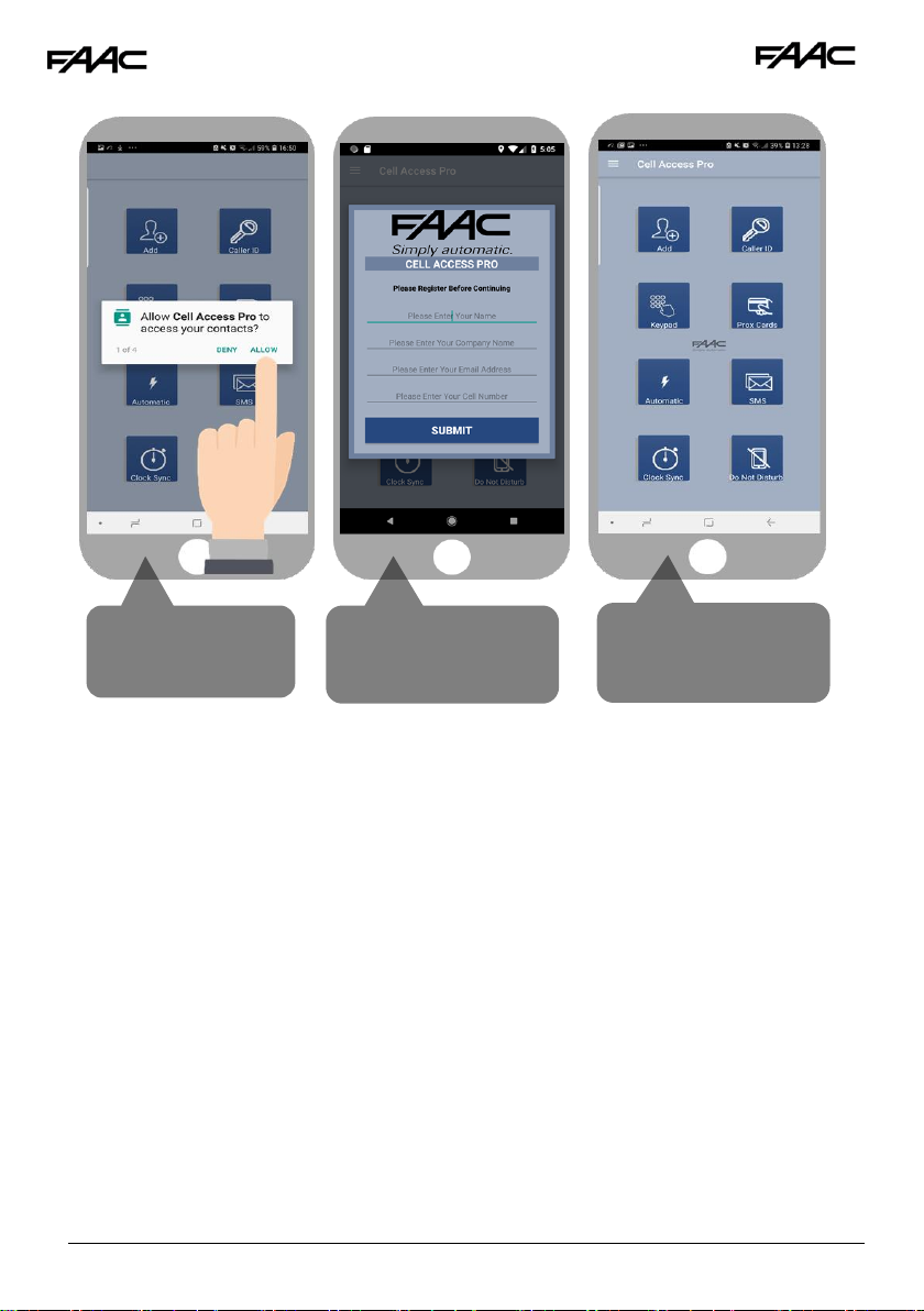
10
Accept and allow all
permissions (Android
version shown)
After you send the
registration email, go
back to the app
To register first time,
enter your name, email
and cell phone
Page 11

11
Programming a Brand-New Install
Programming an EXISTING Install
Enter site or customer name, and INTERCOM PHONE NUMBER
If Engineers and user pass codes are at default then do not change
these. Once completed, you are ready to begin programming.
Now you are ready to begin programming!
Page 12

12
Programming
Now that you have either entered a new client, or selected an existing client from the client list,
you are now ready to begin programming.
Step 1A: Check Reception
Go to MORE>INFO to reveal the screen shown.
Press the reception check button. On Android the app
will automatically send a SMS string (*20#) to the
intercom.
On iphone, users will be taken to their SMS
screen to confirm before sending the string.
The intercom should reply with a signal level between 1
& 31.
1-12
Poor
13-20
Medium
21-31
Good
For good performance, signal level should be at least
13 or better.
TIP: If signal is lower than recommended, then take
IMMEDIATE action. Change network if possible, or use an
optional high gain antenna. Check power cable is within
recommended specification. (Poor power cable can
lower reception).
SMS message sent to the intercom
SMS reply to your phone
Step1C: Reboot the Intercom
The intercom will need to be rebooted in order to log on to the network with the new APN which you
have stored. If you send another reception check (*20#), you may find that if it was on 3G signal
strength before, that it is now on 4G signal.
Step1B: Set APN (for VOLTE / 4G voice calling)
This feature may need to be set in order to make 4G voice calls with At&T a
reseller of At&T. Check the APN of your provider, enter it in the blue section
below & send as SMS to the intercom. TIP: For At&T cards from At&T store
use “nxtgenphone”.
9999#97APNinfo#
Pass code
Function code
APN info for network
Page 13

13
Step2: Activate Clock Sync
This feature makes the intercom send itself a SMS after a
power failure.
This feature must be activated to maintain proper time
(the intercom re-calibrates its time from an incoming
SMS message).
SMS Programming Format:
9999#86telephonenumber#
Pass code
Function code
Phone number of the SIM
card in the intercom
Step 3: Activate Daily
Activity
This feature is needed for 2 reasons:
1.To prevent some cellular carriers
disconnecting the 4G LTE due to inactivity
on the device.
2.To keep time synchronisation in regions
where there are summer daylight saving
time changes.
9999#87??#
Pass code
Function code
1-99 days
00= no SMS sheduling
It is recommended to set the number of days
to 01 which will send SMS every day.
Depending on carrier provider, this may be
chargeable to the customer.
NOTE: Must be 2 characters, e.g. 01, 02 etc.
Page 14

14
Step5: Programming Caller ID
access numbers (100 max).
1. Simply enter cell phone numbers of visitors
whom should have access with caller ID (up
to 4 at a time).
2. Press SAVE. Note: iphone users will be taken
to their SMS screen to confirm the SMS string
(press send).
3. The intercom should reply with an SMS to
your phone showing the SMS string and an
OK status.
SMS Programming Format:
9999#72telephonenumber#72telephonenumb
er#72telephonenumber#72telephonenumber#
To delete a number:
9999#73telephonenumber#
To delete all numbers:
9999#73*#
Step4: Programming Numbers
for the intercom to call
1.Press the SINGLE home icon for a 1 button
system, or MULTI for a 10 button system.
2. Simply enter cell phone numbers and/or
landline phones which the intercom is to call
when the call button is pressed. (10 button
model please enter button number).
3. Press SAVE. Note: iphone users will be taken to
their SMS screen to confirm the SMS string (press
send).
4. The intercom should reply with an SMS to your
phone showing the SMS string and an OK status.
SMS Programming Format:
9999#111telephonenumber#
Pass code
Function code
(add number)
Data
Button number
(1-10)
Telephone number
position 1-4
Page 15

15
Additional Features
To delete a number:
9999#73telephonenumber#
To delete all numbers:
9999#73*#
Time restricted Caller ID
(20 users)
Enter phone number of visitor
Enter start time in 24hr format (military style) with
no colon. E.g. 8.30am = 0830
Enter end time in 24hr format (military style) with
no colon. E.g. 1.30pm = 1330
Select the days which access are to be
granted
SMS string for time restricted caller ID:
9999#72#day,day,day#time1,time2#number#
Pass code
Function code
Enter start and end time in
24hr 4 digit format (no colon),
and separate with comma. e.g.
0800,2300
Select days (up to 7)
3 digit format, separate with
commas, e.g. mon,tue,wed
Number
Page 16

16
Permanent Keypad Code
Stores up to 200 codes, all of which can be used to gain
access 24/7.
Choose relay 1 or relay 2 (pedestrian option)
1 second for gate systems or strike lock. 3-10
seconds for magnetic locks. Can also enter
longer time for holding gates open for a predefined period.
SMS String for adding keypad codes:
9999#811code#time#
Pass code
Function
code
4 digit user
code
1 = Relay 1
2 = Relay 2
=SECONDS
1-9999
0 = Latching
Time Restricted Code
Stores up to 20 codes which can be restricted to pre-set
times and days of the week. (Relay 1 only).
Enter a 4 digit code
Enter start time in 24hr format (military style) with
no colon. E.g. 8.30am = 0830
Enter end time in 24hr format (military style) with
no colon. E.g. 1.30pm = 1330
Select the days which access are to be
granted
SMS String for adding keypad codes:
9999#83#day,day,day#time1,time2#code#
Pass code
Function code
Enter start and end time in
24hr 4 digit format (no
colon), and separate with
comma. e.g. 0800,2300
Select days (up to 7)
3 digit format, separate
with commas.
E.g. mon,tue,wed,thu,fri
4 digit code
Enter a 4 digit code
Page 17

17
Proximity Cards (Optional)
Cards can be added by serial number printed on the
card. There are 3 types of card stored.
Ensure to select your correct intercom model.
(4G models can store a name against each
card for reference).
Time restricted Prox cards (cards that will only
work during pre-set times and days of the week
Temporary Prox cards which auto expire in a
pre-se time.
Check stored Prox cards. Intercom will reply with
SMS message.
Temporary Code
Stores up to 30 codes which will auto expire after the pre-set
time has elapsed.
Enter a 4 digit code
Enter time in hrs (1-168)
SMS String for temporary code:
9999#82#hours#code#
Pass code
Function
code
Can be between
1-168 hours
4 digit code
Only on selected models!
Page 18

18
Enter card users name (6 digits max)
24/7 cards
Enter card serial number (10 digits)
SMS String for adding Prox cards/tags:
9999#611cardID#time#name#
Pass code
Function
code
10 digit card ID
1 = Relay 1
2 = Relay 2
=SECONDS
1-9999
0 = Latching
6 digit
name
xxxxxxxx
Choose relay 1 or relay 2 for activation
1 sec for gates or strike lock. 5-10 secs for mag
lock. 0 = latching
Time Restricted Prox Cards
Store up to 20 cards which only work during pre-set
days and times of the week. (Relay 1 only).
Enter start time in 24hr format (military style) with
no colon. E.g. 8.30am = 0830
Enter end time in 24hr format (military style) with
no colon. E.g. 1.30pm = 1330
Select the days which access are to be granted
Enter card ID (10 digits)
SMS String for time restricted card/tag:
9999#63#day,day,day#time1,time2#cardID#
Pass code
Function code
Enter start and end time in
24hr 4 digit format (no
colon), and separate with
comma. e.g. 0800,2300
Select days (up to 7)
3 digit format, separate
with commas.
E.g. mon,tue,wed,thu,fri
10 digit ID
xxxxxxxx
Only on selected models!
Only on selected models!
Page 19

19
Deleting cards
This screen allows any known card ID to be deleted (by
serial number), and it will also show the last stored cards for
each type of card.
SMS String for deleting a known card:
9999#64cardID#
Pass code
Function
code
Card ID to be deleted
Deleting ALL cards: 9999#64*#
Enter known card ID (10 digits)
xxxxxxxx
Delete all stored cards and start again.
Auto Expiring Temp Cards
Store up to 30 cards which auto expire within a certain
time frame. (Relay 1 only).
SMS String for temporary card/tag:
9999#62#hours#cardID#
Pass code
Function
code
Can be between
1-168 hours
Card ID
Enter card ID (10 digits)
Enter countdown time in hours (1-168)
xxxxxxxx
Only on selected models!
Page 20

20
Automatic Open/close
Set up to 20 auto trigger, latch or unlatch
times to control gates, depending on the
setup of the gate system
For step-by-step setup, use trigger times to
open or close gates as required.
For auto-closing gates, use latching and
unlatching commands to control open
1234#1#day,day,day#time#
USER
passcode
Command:
1=trigger relay 1
2=latch relay 1
3=unlatch relay 1
4=trigger relay 2
5=latch relay 2
6=unlatch relay 2
Enter time in 24hr format (no colon)
Select days (up to 7)
3 digit format, separate with commas.
E.g. mon,tue,wed,thu,fri
1.Pick the event
2.Enter time in 24hr format, no colon.
3.Select the days required.
Page 21

21
App Control of Gates
Relay 1 – Momentary (1234#1#)
Relay 1 – Latch / HOLD (1234#2#)
Relay 1 – Unlatch / UNHOLD
(1234#3#)
Relay 2 – Momentary
(1234#4#)
Relay 2 – Latch / HOLD
(1234#5#)
Relay 2 – Unlatch /
UNHOLD (1234#6#)
Gates can be controlled
from the APP. Take care
not to use the LATCH
command with a strike
lock as it can cause
damage to the lock.
Do Not Disturb
Use this screen to set the ACTIVE time for the call button. Any
button press outside of these times will be ignored by the
intercom.
Quick enable / disable button
Set start and end time for button active times
(24hr format, no colon). E.g. 8.30am = 0830.
Set the days in which calls should be received,
and do not select days which calls should be
ignored.
9999#21#day,day,day#time1,time2#
Pass code
Function code
Enter start and end time in 24hr 4 digit
format (no colon), and separate with
comma. e.g. 0800,2300
Select days (up to 7)
3 digit format, separate with commas.
E.g. mon,tue,wed,thu,fri
To activate, enter the following code:
1234#21#ON# (change ON to OFF to disable again).
Page 22

22
Out of Hours / After Hours
The number stored in this screen will receive calls from the
intercom after hours if the do not disturb feature is set. This is
useful for commercial installs to call a manager after
normal business hours.
Enter phone number to receive out of hours calls
Enter button number (enter 1 for 1 button unit)
9999#211telephonenumber#
Pass code
Function code
(add number)
Data
Button number
(1-10)
Telephone number
position 1-4
Programming codes
There are 2 main SMS programming pass codes
on the intercom. One for the installer (default
9999), and the other for the user/homeowner
(default 1234). It is advised to change these from
the defaults in order to help maintain property
security. Note, user and programmer code
cannot be the same as each other.
If changing default codes, then you will now
need to update the client list before you can
do any further programming.
If the 1234 user access code is changed,
then you will also need to change it on the
home owners app.
SMS Strings:
9999#01XXXX# (X=new programmers
code)
9999#02XXXX# (X=new user access code)
Page 23

23
Ringing Times
In order to prevent unanswered calls going to
voicemail (which will prevent the intercom rolling
to then next phone number), you can adjust the
ringing time to end the call before voicemail is
picked up.
Enter time in seconds (1-99, default = 20)
SMS strings:
9999#45XX# (X=dialling time for first number)
9999#46XX# (X=dialling time for second number)
9999#47XX# (X=dialling time for third number)
9999#53XX# (X= talking time in seconds, 9999
max)
Volumes
Adjust microphone and speaker volumes (1-9,
default = 5).
If your customer experiences high levels of echo
on their phone when speaking to the gate, try
reducing the microphone sensitivity as much as
possible and also reduce the speaker volume if
possible.
SMS string for Speaker Volume:
9999#3X# (X=1-9, default = 5)
SMS string for Microphone Volume:
9999#4X# (X=1-9, default = 5)
Page 24

24
Information
This screen is very useful for retrieving information from the
intercom and its status. E.g. keypad codes, or state of the
relays.
*20#
SIG = 21 4G
*21#
O:5559994321
O:5557811234
I:5559994321
O=dial out no.
I=dial in no.
Multiple SMS will
be sent
FW version and
sig strength will
be sent
*22#
Open
Relay1=on
Relay2=off
“open” refers
to state of the
“status” input
connection in
the intercom.
Relay 1 and 2
will show ON if
latched.
1234#26#
NORM:xxxx
PLAN:xxxxx
TEMP:xxxxx
1234#25#
NORM:xxxx
PLAN:xxxxx
TEMP:xxxxx
NORM: 24/7 cards
PLAN: time restricted cards
TEMP: Temporary cards
NORM: 24/7 codes
PLAN: time restricted codes
TEMP: Temporary codes
*23#
0930-05/01/19-code-XX34
Last 20 events are listed, 4 events
per SMS, most recent first
Last 2 digits of keypad code
used
Event type
Date & time
Page 25

25
Complete list of parameters
The table below show the complete list of features.
Programming messages below must begin
with 9999# (assuming 9999 is still the programming passcode)…
Changing pass codes
9999#01????#
Change programming password
9999
9999#02????#
Change access control password (SMS control of relays, or
non-stored numbers can call intercom & enter code to
activate output 1).
1234
9999#03????#
Change monitoring mode password (user can call the
intercom, enter this pass code to listen in and speak)
5555
Dial out numbers
9999#1XY????#
Store dialling out numbers. (X = button number 1-9 & 0 for
button 10) (Y = number dialled 1-4) (???? = phone number)
N/A
9999#1XY*#
Delete a dial out number. (X = button number) (Y = number
position 1-4)
N/A
Volume controls
9999#3?#
Speaker volume. Where ? = 1-9. 1 = lowest, 9 = highest.
5
9999#4?#
Microphone volume. Where ? = 1-9. 1 = lowest, 9 =
highest.
5
Timings
Relay Times
Relay default trigger times are 1 second. Use this feature
to change a relay for a longer time perhaps for a
magnetic door lock or to make one relay a momentary
relay and the other a 1 hour relay for example.
SMS string for relay 1:
9999#50XXXX# (X=time in seconds, 1-9999)
SMS string for relay 2:
9999#51XXXX# (X=time in seconds, 1-9999)
Enter time in seconds (1-9999)
Page 26

26
9999#50?#
Relay 1 time. ? = seconds, 1-9999
1 sec
9999#51?#
Relay 2 time. ? = seconds, 1-9999.
1 sec
9999#45??#
Calling time for first number, adjust this to avoid voicemail
picking up a call (10-99 secs)
20 secs
9999#46??#
Calling time for second number, adjust this to avoid
voicemail picking up a call (10-99 secs)
20 secs
9999#47??#
Calling time for third number, adjust this to avoid voicemail
picking up a call (10-99 secs)
20 secs
9999#53????#
Talking time. 5-9999 seconds.
60 secs
9999#55??#
Max monitoring time (for listen in mode when calling the
intercom) 00-60 mins. 00 = no limit.
10 mins
Scheduled service calls
9999#
77number#
Store a service number to receive a scheduled call or SMS
from the unit. Useful for SIM cards which are not often used
to prevent switch off by the network provider.
N/A
9999#57??#
Set the time schedule for the intercom to make a scheduled
call or SMS to the service number. 00-60 day time schedule.
00 = no call or SMS.
00
9999#58?#
Choose between making a scheduled call or scheduled
SMS. 1 = SMS. 2 = call.
1
9999#77*#
Delete the stored service number
N/A
Caller ID features
9999#
72number#
Store caller ID number. Max 14 digits. Only last 6 digits
compared.
N/A
9999#
73number#
Delete caller ID number.
N/A
9999#73*#
Delete all caller ID numbers
N/A
Service & diagnostic messages (no passcode required for some of these!)
*20#
Check reception level 1-31 (no passcode needed)
N/A
*21#
Check stored numbers. O = dial out number. I = dial in
number. E = end of message. (no passcode needed)
N/A
*22#
Check input status and relay status. (No passcode needed)
N/A
*23#
Sends SMS messages of the last 20 events.
N/A
1234#25#
Check stored keypad codes.
N/A
Keypad Programming
9999#
81Xcode#time#
Permanent codes - X=1 or 2 for relay 1 or 2. Code = 4-6
digits. Time = 1-9999 seconds, or 0 for latching code.
N/A
9999#
83#day,day,day
#time1,time2#
code#
Time restricted codes
Day = day of the week e.g. mon,tue,wed,thur,fri.
Time1 = start time. Time2 = end time (24 hr format, no
colon. E.g. 11:30pm = 2330. 8.30am = 0830.
Code = pin code 4-6 digits.
N/A
9999#
82#hours#
Temporary codes
Hours = time to expire in hours (1-168 hours).
N/A
Page 27

27
code#
Code = Pin code 4-6 digit code.
9999#84code#
Delete code – Code=known code to be deleted.
N/A
9999#84*#
Delete all codes.
N/A
Notifications
9999#80X#
X=1 to disable. X=2 to enable.
N/A
9999#78XXX#
X=phone number to send notifications to. (*=delete
number)
N/A
9999#79text#
X=text to send to the receiving phone e.g. “gate opened”
N/A
Automatic Time Clock Trigger Times
1234#X#
day,day,day#
time#
X=1,2.3 (trigger, latch, unlatch relay 1) 4,5,6 (relay 2)
Day = days of the week (mon,tue,wed,thur,fri,sat,sun)
Time = time of day (24 hr format, no colon. E.g. 8:30am =
0830)
N/A
1234*X#
Delete ALL automatic trigger times.
N/A
Clock Sync - Auto Time Calibration after Power Fail
9999#86XXX#
X=telephone number of SIM inside the intercom.
N/A
9999#86*#
Delete the phone number.
N/A
Summer Daylight Auto Correct
9999#87??#
?? = number of days between SMS calibration SMS should
be sent. 0 = no message sending.
N/A
Do Not Disturb (push button de-activated during set times)
1234#21#ON#
ON = activated. OFF = de-activated.
OFF
9999#
21#day,day,day
#time1,time2#
Enter all active days during which button should operate.
Enter start and end time button should operate
(24 hr format, no colon. E.G 8:30am = 0830)
N/A
Alternate Number to Call During Do Not Disturb Times.
9999#
21X????#
X = button number (1-9. Enter 1 for 1 button system. Enter 0
for button 10)
???? = Alternative phone number to call out of hours.
Restore Defaults
9999#999#
Send with passcode string to clear all programming.
N/A
Control by SMS
This intercom allows the user to send SMS commands to control the relays and check status as
follows…
1234#1# - Relay 1 momentary trigger.
1234#2# - Relay 1 latch ON or hold ON.
1234#3# - Relay 1 unlatch or switch OFF.
1234#4# - Relay 2 momentary trigger.
1234#5# - Relay 2 latch ON or hold ON.
1234#6# - Relay 2 unlatch or switch OFF.
Page 28

28
Troubleshooting guide
Q. The unit will not power up. No LEDs on.
A. Check power supply voltage at intercom is within 14.8V DC. Cable length from PSU to
intercom should be less than 25 feet and in 14 gauge. Check the fuse.
Q. The unit powers up but is not showing network reception or will not respond to SMS.
A. This means the unit is not able to detect the network for some reason.
-Power off the unit, remove the SIM and check it in a mobile phone to verify it can make a call
and has calling credit.
-Disable any PIN code request if active on the SIM card.
-Check the SIM is a standard voice capable SIM. If you are unsure, contact your SIM card
provider to verify. Compatible networks are At&T and T-Mobile.
-Check the reception is medium or good. Poor reception is not sufficient.
-Power off, remove the SIM, use fine sand paper to lightly sand the SIM pads and contacts on the
GSM unit, lightly bend the contacts upwards so that they make better contact with the SIM and
try again.
Q. The unit calls the first number, but there is not enough time to answer before it diverts to the
next number.
A. Increase the no answer time as per programming instructions.
Q. The unit calls the first number but voicemail comes on before it can ring the second number.
A. Decrease the no answer time as per programming instructions.
Q. The caller ID part does not work.
A. Be sure to program the caller ID part under 72 feature. If your number is a private or number
withheld, then it will not work.
-Even if you have already programmed a number to receive a call from the intercom, if you also
want that number to have caller ID access, it must be programmed under the 72 feature also.
-Ensure the number is entered as you would normally dial it from another phone.
-For US customers, ensure the numbers have been entered with a leading 1. If this does not work,
try again without the leading 1.
Q. There is no audio from the gate, but the person at the gate can hear ok.
A. This can be due to low reception or excessively long power cables.
-Check reception level by *20#.
-Change SIM card if necessary to another network which may have better coverage.
-Purchase a high gain antenna.
This may also be caused by a defective microphone, water on a microphone from a sprinkler for
example, or dirt/insects blocking the microphone hole. If reception is optimum and the problem
persists, contact your supplier or installer.
Q. The audio quality that can be heard on the remote telephone is poor or humming (buzzing).
A. A small amount of GSM buzz can be considered normal on GSM intercoms, but not so much
that causes inability to hear the person speaking. This is a symptom of poor reception. Try above
steps on checking and improving reception. Consider fitting an external high gain antenna.
Page 29

29
Q. The trigger keys do not work when the intercom calls a phone.
A. Check if you can hear the relay clicking at the gate when the keys are pressed during a call. If
it can be heard, then the system is working, check wiring between the relay and the lock or gate
panel. If the relays do not make a clicking sound, then check this feature on a different mobile
cell phone or landline. If it works on a different phone, check the settings on the phone in
question under DTMF tones.
Failure of DTMF tones to operate correctly is also a symptom of low reception or insufficient
power cabling. Check steps above on improving reception or addressing the power problem.
-Also check that the relays are not already latched with the *22# command. If they are latched,
they need unlatched before the trigger keys will work.
-Sometimes excessively long power cables or thin power cables can cause this problem. Prove it
by connecting a temporary extension lead and the power supply directly to the unit.
Q. The system was operating the gates fine, but now it will not trigger the gates.
Frequently, this is cause by the user accidentally latching the relay. This latches the output relay
permanently on. Send the intercom the following SMS *22#. The intercom should reply with a
message detailing the relay status.. If it has been latched, then the message will state “the relay
is ON”. In this case refer to the user guide to read how to unlatch it again.
Q. The unit no longer calls out to phones but I can make a call to it from my phone.
A – Check there is balance on the SIM card.
A – Switch off the power, remove the SIM, put it into a phone, and check that a call can be
made from a phone. This will verify if the SIM is still working and in service.
Q. The Android App shows an error message “Command Failed” when I try to use a function.
A – Go to phone settings/application manager/cellbox prime/permissions, and ensure all
permissions are turned ON. Also ensure the app settings screen has a valid phone number
stored.
Change History
Key:
P = Panel version H = Hardware PCB version S = Software version
Version
Reason for change
Date
P H S
Page 30

30
Warranty Terms
To the original purchaser only:
FAAC International, Inc., warrants, for twenty-four (24) months from the date of invoice, the gate
operator systems and other related systems and equipment manufactured by FAAC S.p.A. and
distributed by FAAC International, Inc., to be free from defects in material and workmanship
under normal use and service for which it was intended provided it has been properly installed
and operated.
FAAC International, Inc.’s obligations under this warranty shall be limited to the repair or
exchange of any part of parts manufactured by FAAC S.p.A. and distributed by FAAC
International, Inc. Defective products must be returned to FAAC International, Inc., freight
prepaid by purchaser, within the warranty period. Items returned will be repaired or replaced, at
FAAC International, Inc.’s option, upon an examination of the product by FAAC International,
Inc., which discloses, to the satisfaction of FAAC International, Inc., that the item is defective.
FAAC International, Inc. will return the warranted item freight prepaid. The products
manufactured by FAAC S.p.A. and distributed by FAAC International, Inc., are not warranted to
meet the specific requirements, if any, of safety codes of any particular state, municipality, or
other jurisdiction, and neither FAAC S.p.A. or FAAC International, Inc., assume any risk or liability
whatsoever resulting from the use thereof, whether used singly or in combination with other
machines or apparatus.
Any products and parts not manufactured by FAAC S.p.A. and distributed by FAAC International,
Inc., will carry only the warranty, if any, of the manufacturer. This warranty shall not apply to any
products or parts thereof which have been repaired or altered, without FAAC International, Inc.’s
written consent, outside of FAAC International, Inc.’s workshop, or altered in any way so as, in the
judgment of FAAC International, Inc., to affect adversely the stability or reliability of the product(s)
or has been subject to misuse, negligence, or accident, or has not been operated in
accordance with FAAC International, Inc.’s or FAAC S.p.A.’s instructions or has been operated
under conditions more severe than, or otherwise exceeding, those set forth in the specifications
for such product(s). Neither FAAC S.p.A. nor FAAC International, Inc., shall be liable for any loss or
damage whatsoever resulting, directly or indirectly, from the use or loss of use of the product(s).
Without limiting the foregoing, this exclusion from liability embraces a purchaser’s expenses for
downtime or for making up downtime, damages for which the purchaser may be liable to other
persons, damages to property, and injury to or death of any persons.
FAAC S.p.A. or FAAC International, Inc., neither assumes nor authorizes any person to assume for
them any other liability in connection with the sale or use of the products of FAAC S.p.A. or FAAC
International, Inc. The warranty herein above set forth shall not be deemed to cover
maintenance parts, including, but not limited to, hydraulic oil, filters, or the like. No agreement to
replace or repair shall constitute an admission by FAAC S.p.A. or FAAC International, Inc., of any
legal responsibility to effect such replacement, to make such repair, or otherwise. This limited
warranty extends only to wholesale customers who buy directly through FAAC International, Inc.’s
normal distribution channels. FAAC International, Inc., does not warrant its products to end
consumers.
Consumers must inquire from their selling dealer as to the nature and extent of that dealer’s
warranty, if any. This warranty is expressly in lieu of all other warranties expressed or implied
including the warranties of merchantability and fitness for use. This warranty shall not apply to
products or any part thereof which have been subject to accident, negligence, alteration,
abuse, or misuse or if damage was due to improper installation or use of improper power
source, or if damage was caused by fire, flood, lightning, electrical power surge, explosion, wind
storm, hail, aircraft or vehicles, vandalism, riot or civil commotion, or acts of God.
Page 31

31
Regulatory Compliance
FCC Id: 2ALPX-PE-4GA
(Multiple variation part numbers registered under this main part number)
Grantee: Advanced Electronic Solutions Global LLC
This device complies with Part 15 of FCC rules. Operation is subject to the following two
conditions: (1) this device may not cause harmful interference, and (2) this device must accept
any interference received, including interference that may cause undesired operation.
Output power listed is ERP below 1GHz for Part 22 and EIRP above 1GHz for Part 24. RF
exposure compliance is addressed for 1.1310 and 2.1091 MPE limits. The antenna(s) used
for this transmitter must be installed to provide a separation distance of at least 20 cm from
all persons. End Users must be provided with transmitter operation conditions for satisfying
RF exposure compliance.
Page 32

32
Note: For legal reasons, telephone technical support is for registered and
qualified product dealers only. Home owners and end users should contact
their local dealer for product technical support
 Loading...