

Page 1
1 | P a g e
Installation Instructions
FAAC-Pro 2-4GA
PROFESSIONAL INSTALL ONLY
Do NOT give this manual to end user!
FAAC International Inc.
Headquarter & East Coast Operations
3160 Murrell Rd
Rockledge, FL 32955
Tel. 800 221 8278
www.faacusa.com
FAAC International Inc.
West Coast Operations
357 South Acacia Avenue
Fullerton, CA 92831
Page 2

2 | P a g e
Index
Section
Pages
Site Survey
3
Overview of Product
4
Modem
4
A look inside the product
5
Power to Call Box
6
Network Cables and Modem
7
Power Module in Detail
8
Main Intercom Module in Detail
9
Keypad Module in Detail
9
Relay Wiring Tips
10
Powering On
11
App Setup & Config
11
Answering on Android
17
Answering on Apple
18
Adding Additional App Users
19
Other Settings
20
Sounds, Volume and Speech
21
Using the App
22
Keypad Programming
23
Using the Keypad
25
Troubleshooting
25
Revision Changes
26
Warranty Terms
26
Page 3

3 | P a g e
Mbs
Slow Fast
Site Survey
YES!
I have 4G signal at the gate with my phone! If
not, STOP. You will need some! Try a different
network provider.
YES!
I have at least 1 Mb UPLOAD speed. If not
STOP! This system may operate intermittently
remotely or have delayed PUSH notifications.
Page 4
4 | P a g e
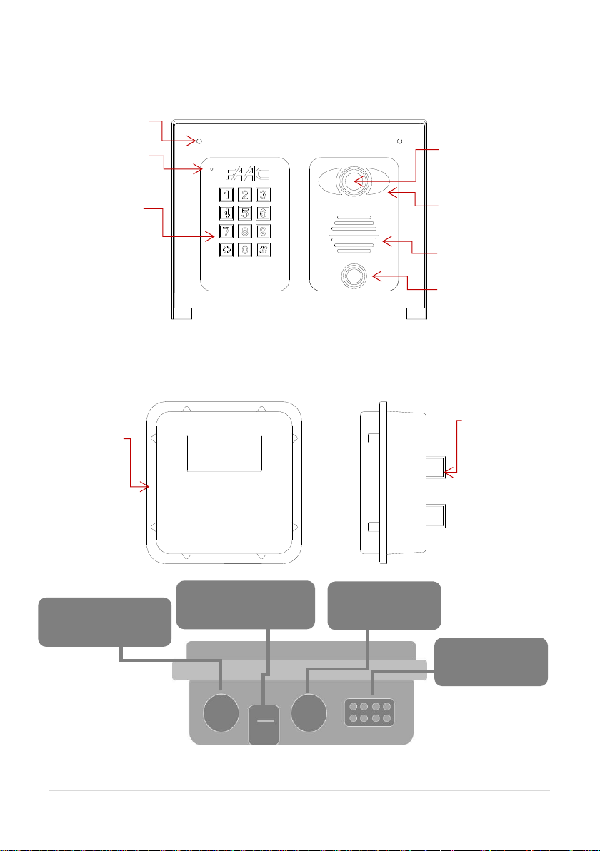
Overview of Product
Microphone
Optional
Keypad
Security
screw
access
Camera
Night vision LEDS
(short range, up to
5 feet)
Speaker
Call button
Modem
weatherproof
housing
Modem
Front view
Side view
Mounting
holes (wall or
pole
mountable)
POE Power Supply
RJ45 connection
Sim Card Holder
(DATA/IOT Sim only)
LED Indicators
LAN RJ45
Connection
Bottom
View
Page 5
5 | P a g e
Now let’s have a look inside...
Pedestal
mounting holes
Main intercom
module
Speaker
volume
Camera
module
Optional keypad
module
Code button
Call button
Power filter
board
Page 6
6 | P a g e
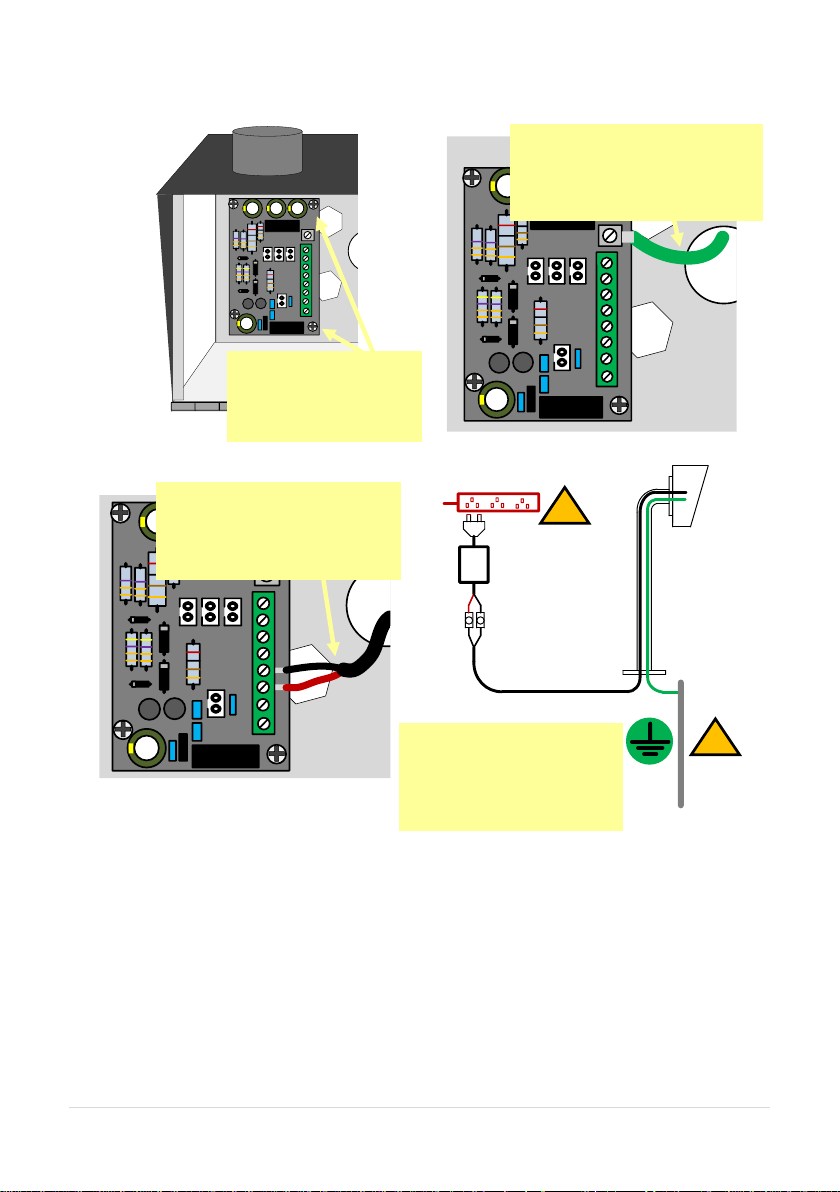
Power to Call Box
!
!
3
Use minimum 16-gauge wire
from the 24v DC adaptor
provided to the terminals
shown.
1
IF necessary, remove
4 screws and remove
the power conditioning
module.
After fitting the box to the
gooseneck, re-fit the module
and connect a 14-gauge earth
wire to the earth terminal.
2
Earth Rod
(close as
possible)
Maintain manufacturer’s
warranty by adhering to
the guidelines shown. Use
110v surge protected
supply.
Surge protected 110v
4
24v DC PSU
16-gauge MIN
25 feet MAX
Call box
Page 7
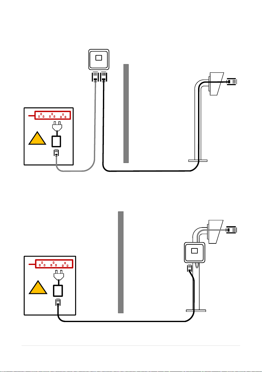
7 | P a g e
Network Cables and Modem
!
!
Modem (Keep high)
Perimeter wall
/ fence
30 foot Patch
cable
(included)
Pedestal
Weatherproof
enclosure
6 foot patch
cable
(included)
Surge
protected
110v supply
Modem +
Antenna
(Keep high)
Perimeter wall
/ fence
30 foot Patch cable (included)
Surge
protected
110v supply
Weatherproof
enclosure
POE
PSU
POE
PSU
Option 1
Option 2
(Mounting on Pedestal)
Page 8
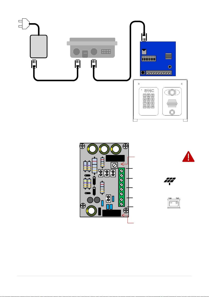
8 | P a g e
POE Power
supply
POE
POE
LAN
LAN
Modem
Main intercom
module
WARNING:
Do not send POE power to the intercom.
Only the modem is powered with POE.
The intercom is powered separately with
24v DC.
- + +
-
+
-
1A quick blow input fuse
Power
Module in
Detail…
+
-
Earth Rod MUST be
connected for warranty
Power out
Solar Panel IN
24vdc IN (do not use 12v here)
12v DC IN or 12v
Battery HERE
Page 9
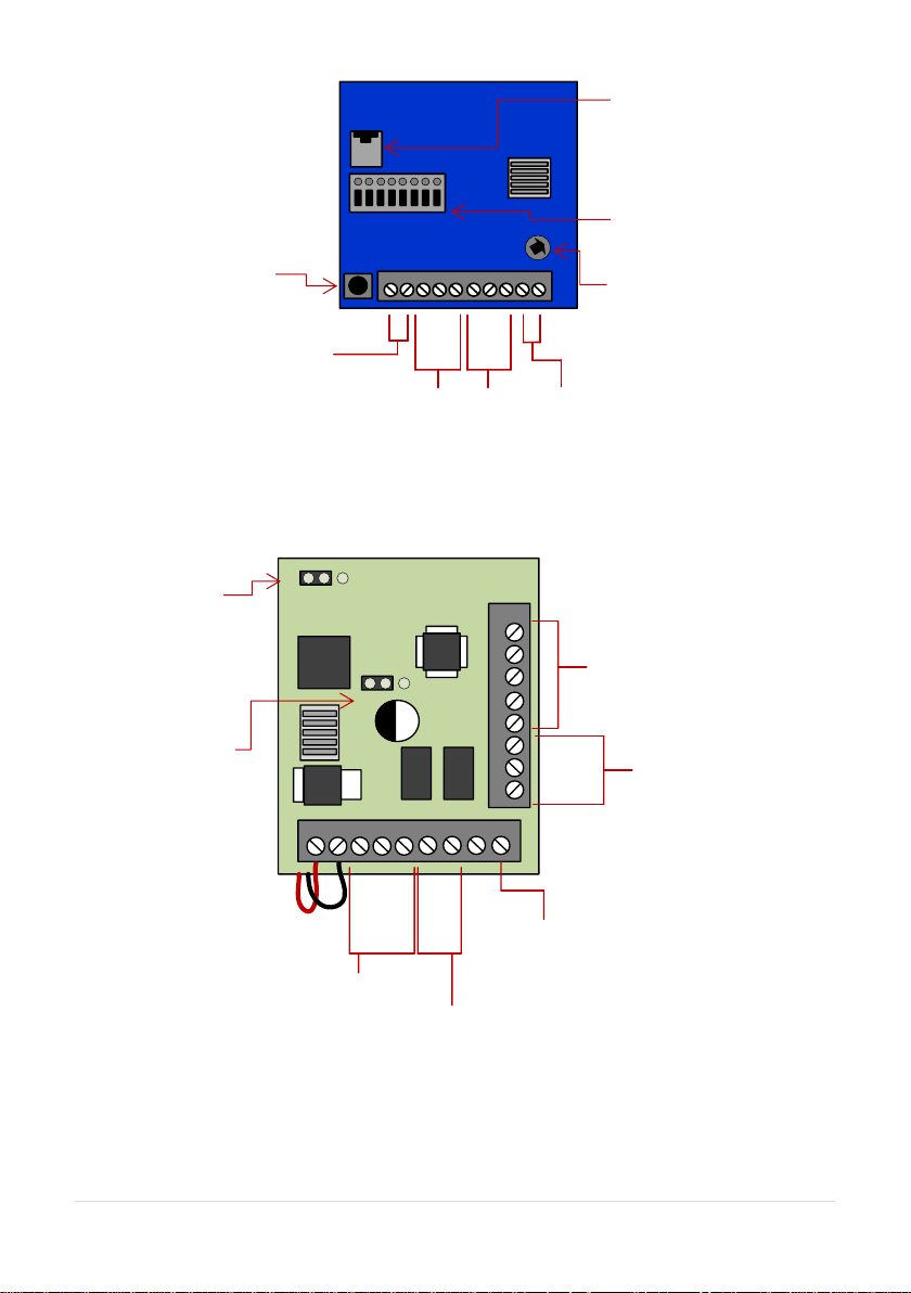
9 | P a g e
Keypad Module in Detail…
Main
Intercom
Module in
Detail...
RJ 45 socket for
CAT5 Ethernet
connection to
router / modem
Quick connect
terminals for Ethernet
connection to
router/access
point/switch
Speaker volume
Code button
24v DC (pre-wired)
from power module
N/C
COM
N/O
N/O
COM
N/C
Relay1
Relay2
Exit button (N/O)
N/O
N/C
COM
N/O
N/C
Relay1
(1000 codes)
Relay2
(100 codes)
Egress
Wire N/O exit button
to here & GND (-)
Not used
Relay3
(100 codes)
Full / Auto
(keypad
illumination)
Relay 2
N/O and N/C
Common selector
24v DC Power
(Pre-wired)
Page 10

10 | P a g e
Relay Wiring Tips
Intercom Module
Pedestrian Gate
Magnetic Lock
Separate Lock
Power Supply
Optional Exit
button (N/C)
Automatic Gates
Gate Controller
unit
Remember to wire keypad relays to
lock or gates as well as the main
intercom module.
Note: Relay 2 can be set to N/O or
N/C as per keypad detail section.
N/O
COM
N/C
COM
Note: Never connect any electric
lock to the power supply provided
with the intercom. It is good practice
and professional to power a lock
from a separate power supply.
Page 11

11 | P a g e
Powering on
App Setup & Config
Step 1: Install the APP
Download and install the app
on the end-user’s phone.
Search for wifi PRO 2 and find
the icon, or scan the QR code
if the phone has a QR scan
app.
Tip: Be sure to accept ALL
permissions during install,
otherwise you will experience
problems later!
The second LED will flash if you have medium 3G signal.
The second LED will stay solid if you have medium 4G signal.
RF (signal level)
S
I
M
S
Y
S
SIM – The sim LED will come on if there is a sim inserted.
RF – The first LED will flash if you have low 3G signal.
The first LED will stay solid if you have low 4G signal.
N
E
T
2
The third LED will flash if you have high 3G signal.
The third LED will stay solid if you have high 4G signal.
SYS – The system LED will flash when active, solid when inactive.
NET2– This LED flashes when active.
Page 12

12 | P a g e
Step 2
Step 3
Step 4
Open the APP and press the Settings
button. Then press the add intercom
button.
Enter the intercom Bell I.D which can
be found on the main board.
Enter “admin” for the main
user.
Enter “123456789” as the default password and
press the TICK as shown.
A
E
S
-1
2
3
4
5
-X
X
X
X
X
Wait 5 minutes
for the intercom to connect to the
remote servers and the modem to get
full 4G connection.
5 mins
Page 13

13 | P a g e
Step 5
Diagnostic Tips
1. Intercom is showing online status, but the video feed shows “fetching”.
A. This can be caused by poor power cable extended to the intercom or weak 4G.
2. Intercom is not showing online status.
A. This can be caused by weak 4G, dropping in and out due to weak signal.
3. I can see video but there is no audio on the phone or there is no audio at the intercom.
A: This can be caused by the audio settings being too low on the phone, or permissions for the
app were not accepted during app install. Check microphone permissions for the app in the phone
settings.
4. The status is showing online, then connecting, then online again.
A: This is normal when a phone roams between two wifi connections, or between wifi and data.
Make sure the phone is stationary and either has good wifi or a stable data connection
Press the call button.
Press the Video icon to
view live video.
Note: at close proximity,
you will experience acoustic
feedback. This is normal.
If you can see live video
and hear audio, the
intercom has successfully
connected to the network.
Intercom
Calling…
The intercom will send a notification message via GoogleTM PUSH
notification service through the internet to the phone. The
notification will need to be accepted, the phone unlocked, and then
the APP will launch to reveal the visitor and give the user an
opportunity to either accept or reject the call..
Should be
showing ONLINE
status.
If the unit is not
showing online
you are not
connected to the
4G network.
Page 14

14 | P a g e
Alternative set-up
Step 6a
Step 6b
Step 6c
Remove the network/LAN cable before pressing the
code button
Press and HOLD the code button for more than 5
seconds and release. A tone will be heard.
The intercom will now begin to transmit its own wifi
network called BELL-XXXXXX (where XXXXXX is the 6
numerical digits from the serial ID number).
>5 seconds
With the user’s phone, search for available wifi networks and
connect to the BELL network.
TIP: Your phone needs to be within range of the intercom to
detect this network.
Wifi passcode
Enter the default pass code 123456789 and the users phone
should now be connected directly to the intercom.
Press CONNECT on android devices and DONE on apple
devices.
Page 15

15 | P a g e
Step 6a, 6b, 6c
Step 6d, 6e
Step 6f
After pressing
SEARCH, the APP
will now search for
the intercom and
should detect it.
Intercom ID will be auto filled.
Enter “admin” for the main user.
Enter “123456789” as the default password
and press the TICK as shown.
Press the Video icon to
view live video.
Note: at close proximity,
you will experience
acoustic feedback. This
is normal.
TIP: If you can view live
video, and hear
acoustics, then this
proves that the intercom
hardware is working as it
should.
Should be showing
ONLINE status.
Page 16

16 | P a g e
Step 6g
Step 7 - Press the call button.
Intercom
Calling…
The intercom will send a notification message via GoogleTM PUSH
notification service through the internet to the phone. The
notification will need to be accepted, the phone unlocked, and then
the APP will launch to reveal the visitor and give the user an
opportunity to either accept or reject the call..
Reconnect the
network/LAN cable
Wait 60 seconds.
The intercom will
now attempt to
connect to the app
via the 4G modem.
60 secs..
If you can see live
video and hear audio,
the intercom has
successfully
connected to the
network.
If for some reason this
does not work, try
connecting to the wifi
network again and
double check the wifi
password is correct.
Page 17

17 | P a g e
Answering on Android
Swipe down your
notification banner
when called, and press
the Intercom
notification.
Your phone will now
launch the app and
you will see a
snapshot of the visitor
at which point you can
answer or decline the
call.
Press the green icon to
accept.
Page 18

18 | P a g e
Answering on Apple
Note: Various versions of IOS and Android OS will have different notification acceptance
techniques. Please refer to online support for your device if needed.
Swipe the
notification left
Press “VIEW”
Swipe green
icon to answer
Phone will now
launch app
TIP: Make sure ringer switch is
ON and volume is turned up.
TIP: If you don’t get
notifications then check
settings/notifications and
select the app.
TIP: If there is no voice from the
speaker at the gate, check the
iphone microphone permissions in
Settings/privacy/microphone
Page 19

19 | P a g e
Adding Additional APP Users
Additional users MUST be added with individual user names. Do NOT use the same username.
ADMIN Phone
ADMIN Phone
ADMIN Phone
ADMIN Phone
Enter a NEW
username &
password
Note how
existing users
can be deleted
New Phone
New Phone
New Phone
New Phone
Be sure to enter NEW
username & password as
created by the admin
phone.
Page 20

20 | P a g e
Other Settings
Edit Intercom
details
Ring tones
Check APP
version
Add an intercom (can
have up to 6
doors/gates calling one
device)
Add/edit users
Turn off config
mode (extra
security)
Wifi settings &
signal
strength
Set max monitoring
time
Change relay times (1-
9 secs)
Set time zone +
(daylight saving
adjust)
Set max talking
time.
Set max ringing
time (from intercom)
Set sound option.
Duplex, simplex1,
simplex2.
Reboot
intercom
Page 21

21 | P a g e
Sound, Volumes and Speech
This intercom is capable of full duplex speech, which means two people can have a conversation
and appear to speak at the same time. Since various manufacturers of android phones, iphones
and tablets all differ in acoustic performance, and different users may require varying levels of
volume on their own handset, it may be possible to setup some devices in full duplex mode but
others may need to be set in half duplex mode (phone user will press to talk). This may also be
required if a phone is in a particularly noisy environment, or the intercom is located near a busy
main road with high levels of traffic noise.
Choose the speech option which
best suits the individual and he
device being used.
+ - SPK
Suggest 80% MAX
volume
Suggest
50% MAX
volume on
“Press and Hold” option
appears when device set to
half duplex 1 or 2.
Page 22

22 | P a g e
Using the APP
Settings
View Camera &
listen
Thumbnail preview
Home
Call Log (shows
images of visitors
whom calls were
accepted or
previewed on this
device.
If you took
snapshots of a
visitor while on a
call, view them
here.
If you took video
recordings of
visitors, you can
view them here.
Press to extend
talking time
Gate/door release 1.
Momentary press to
TRIGGER.
Press and HOLD for
3 seconds to LATCH
open.
Momentary press
again to UNLATCH
Record video of
visitor to your
phone. (some
versions of phone
need codec
installed to play
this format).
Take pictures of
visitors on your
phone.
Gate/door release 2.
Momentary press to
TRIGGER.
Press and HOLD for
3 seconds to LATCH
open.
Momentary press
again to UNLATCH
End call.
Android users press BACK button to run in
“background” mode or “close app” to save
battery. (notifications will launch app again)
Page 23

23 | P a g e
Keypad overview
This keypad has 3 outputs, all independent from the intercom/app relays. The diagram below
shows the LED indicators which indicate programming and relay status information.
RED when incorrect codes entered and outputs are locked out.
1 2 3
4 5 6
7 8 9
* 0 #
SLOW FLASHING - in normal standby mode.
ON in programming mode.
ON when relay 3 activated.
GREEN when output 1 activated.
RED when output 2 activated.
CLEAR when output 3 activated
FAST FLASHING – Wrong code entered / error.
TIP: After power up, as a security precaution, the keypad cannot be programmed for 60 seconds.
Once this time elapses, you may begin.
TIP: Flashing amber LED is normal standby mode!
Keypad Programming
0 0 0 0 * *
Quick start guide
1) Enter programming mode (amber LED should be ON)
1 0 2 0 0 ? ?? ? #0
2) Enter a new user code...
* *
3) Exit programming mode
4) Enter the new user code to check the relay clicks.
Full Keypad programming
Enter programming mode..
0 0 0 0 * *
Exit programming mode..
* *
Enter a new ENGINEER/INSTALLERS code…
Go into programming mode firstly then enter the following sequence…
Location
0 1 ?? ? ?
4-8 digit code Validate
#
Tip: The engineer code
must be the same length as
user codes. If using a 6 digit
engineers code, then user
codes must also be 6 digits
long etc.
The unit is now in programming mode. Amber LED on the
keypad should remain permanently on. 0000 is the default
programming passcode.
The unit should exit programming mode and the amber LED
should start flashing again.
Replace ???? with your new ENGINEERS
code.
Page 24

24 | P a g e
Enter or delete new user/Homeowner codes
There are 3 groups of user codes. Group 10 for relay 1, group 20 for relay 2, and group 30 for
relay 3. The programming sequence is shown below…
Memory locations
000-999 for relay 1
001-100 for relay 2
001-100 for relay 3
1 0 2 0 0
10= relay 1 codes
(1000 available)
20= relay 2 codes
(100 available)
30= relay 3 codes
(100 available)
? ?? ? #0
2= add code
5= delete code
Pin code 4-8 digits Validate
Example: Add user 31 to have access code 5555 operating relay 2….
2 0 2 0 3 5 55 5 #1
Group 2 Add code Location 31 Pin code 5555 Validate
Programming relay output times and modes…
? ?
0
1 -
0 = start / stop toggle mode (latching)
1-99999 = seconds momentary operation
9 9 9 9 9
or
#
51=relay1
52=relay2
53=relay3
Validate
Delete a user code even if you don’t know the code…
? ? 5 ? ?? #
10=relay1
20=relay2
30=relay3
Delete code ID location to be deleted Validate
Delete an entire group of codes
? ? 0 9 99 #
10=relay1 group
20=relay2 group
30=relay3 group
Super delete code Validate
Programming super user codes…
A super user code can activate any of the 3 relays
Location
0 2 ?? ? ?
4-8 digit code Validate
#
Restoring defaults
When in programming mode, you can enter the following sequence…
9 9 99 #
When the engineers/installers code is forgotten….
Page 25

25 | P a g e
1) Wire a push button (or replicate with wire link) across the Egress terminal and (-)GND.
2) Switch off power for 1 minute.
3) Switch ON power.
4) during the first 60 seconds, press the EG button once to enable the function.
5) Enter the following code..
8 0 08 * *
The keypad should now be in programming mode, ready to accept new data. Change the
installers/engineers code now as per instructions above.
Using the keypad
Using the standard codes…
Once you have exited out of programming mode, simply enter the user code.
Using super user codes
?? ? ? # 1
Activate output 1
?? ? ? # 2
Activate output 2
?? ? ? # 3
Activate output 3
Troubleshooting
It is worth remembering that when you install this intercom, you are literally only supplying 25% of
the overall system. The other 75% already exists with the customer. Namely the router, the wifi
network, and the phones or devices.
Anything can go wrong with any part of that entire system. Therefore, it is a useful exercise to
attempt to prove to the customer that the intercom hardware is working and operational before
attempting to diagnose the root cause, especially when connected wirelessly to a network.
If the intercom is connected via wifi to the network, it is very useful to press and hold the code
button on the board, then connect the phone DIRECTLY to the BELL wifi network (must be within
wifi range of intercom). Open the app, and show the customer that when the phone is connected
directly to the intercom, there is video and two way speech. The job is then to find out what part of
the installation or overall system is causing the problem since the intercom hardware has been
proven as operational.
We can say without doubt that when we do get hardware failures, the above process will not work
and you will not get video and voice to the phone in a direct connection like this.
Below are the most common causes of problems with installs, starting with the most common first.
Problem/error
Symptoms caused
Solution
Wrong power cable (too
Delayed push notifications,
Change the power cable to
Page 26

26 | P a g e
thin) installed from 24v
adaptor to the intercom,
or power adaptor too far
from intercom.
video lag, voice problems,
freezing, relays not opening
the gate.
specifications shown within this
manual.
Additional user added
incorrectly.
Can randomly display status
“id already in use”
When an additional user was
being added, the process was
done incorrectly. Additional users
MUST be added by the admin
device first, with separate
usernames created for each. The
new usernames and passwords
must be used by the new devices
as shown in this manual to logon
to the intercom.
Change History
Top
version
Panel
version
PCB
version
Firmware version
IOS app
version
Android
app version
1 2 1.0
4.11.12.21.20171121
1 1
Warranty Terms
Please note, by installing this product, you are accepting the following warranty terms:
1. The manufacturer’s warranty is a “return to base” 2 year warranty from date of manufacture. This means that
any suspected defective components or items are returned to the manufacturer’s agent for investigation and
diagnosis, and returned at the cost of the customer.
2. The warranty does not cover, nor is the manufacturer or agent responsible for any of the following
whatsoever: Storm damage, lightning or surge damage, flooding, accidental damage, vandalism or deliberate
damage, un-explained corrosion or unusually harsh environments, failure of telephone networks, future uninteroperability between the product and network providers which cause mal-function due to changes
implemented by the phone providers after manufacture of the product, or that which is outside of control of the
manufacturer (e.g. 2G, 3G switch off, removal or inability to obtain VOLTE service), and damage due to not
proper installation.
3. The manufacture in no way accepts liability for any of the following incurred due to a product defect: Cost of
attending site, inconveniences, labor rates, time lost, loss to or damage to property, security breaches, late
payment clauses or breaches of any contracts between the installer and the client.
4. This is a profession install product only. The product is a component of an overall system. Therefore, it is the
responsibility of the installer to certify the safety and compliance of the overall finished system. As soon as this
product is fixed to another item, or connected to another third-party device, then the product has been modified,
and compliance with local regulations in the country of install is strictly the responsibility of the installer.
5. Re-stocking fees may apply to items returned that are found to be non-defective. Complete units will also
attract a re-stocking fee if returned for credit, regardless if a defect is discovered or not. Re-stocking fees may
vary depending on the condition of the item being returned, and whether it can be determined as in brand new
condition. The warranty terms do not entitle customers to an automatic full refund. For more details on returns
procedures and re-stocking fees, contact the agent.
6. Items with physical signs of surge damage are not covered by warranty. Items without visible signs of surge
damage will only be covered by warranty provided photographic evidence is provided from site showing surge
protection has been installed as per instructions in this manual.
Regulatory Compliance
FCC Id: 2ALPX-WIFI-IBK
Page 27

27 | P a g e
Grantee: Advanced Electronic Solutions Global Ltd
This device complies with Part 15 of FCC rules. Operation is subject to the following two conditions: (1) this device may not cause
harmful interference, and (2) this device must accept any interference received, including interference that may cause undesired
operation.
Output power listed is conducted. This device must be installed to provide a separation distance of at least 20 cm from all persons
and must not be co-located or operating in conjunction with any other antenna or transmitter. End-users and installers must be
provided with antenna installation instructions and transmitter operating conditions for satisfying RF exposure compliance. This
device has 20MHz and 40 MHz bandwidth modes.
EU-RED Declaration of Conformity
Manufacturer: Advanced Electronic Solutions Global Ltd
Address: Unit 4C, Kilcronagh Business Park, Cookstown, Co Tyrone, BT809HJ, United Kingdom
We/I declare, that the following equipment (Video intercom), part numbers:
Wifi-iBK, wifi-iB, wifi-ABK, wifi-AB, wifi-BD, wifi-BEK,
wifi-BEik, wifi-Bei, wifi-BFT-KPAD
Complies with the following essential requirements:
EN 301 489-1 V2.2.0 (2017-03) (Electro-Magnetic compliance)
EN 301-489-17 V3.2.0 (2017-03) (Electro-Magnetic compliance)
EN 62479:2010 (Maximum output power)
EN60950-1:2006+A11:2009+A1:2010+A12:2011+A2:2013 (Electrical Safety)
This product is not a complete product until fully installed. It is therefore considered a component
part of an overall system. The installer is responsible to check that the end installation complies
with local regulatory requirements. This equipment forms part of a “fixed installation”
Note: For legal reasons, telephone technical support is for registered
and qualified product dealers only. Home owners and end users should
contact their local dealer for product technical support.
 Loading...