

Page 1
1
EXP-2000
User manual
SPX Expansion interface modules
The EXP-2000 provides additional Door/Panel interface points to most SPX products. The EXP-2000 uses a local
RS-485 network through an SPX gateway device. Additional access points can be added as needed.
EXP-2000
Part 15 Class A
Page 1 of 7
EXP-2000_MAN
Page 2
1
Physical
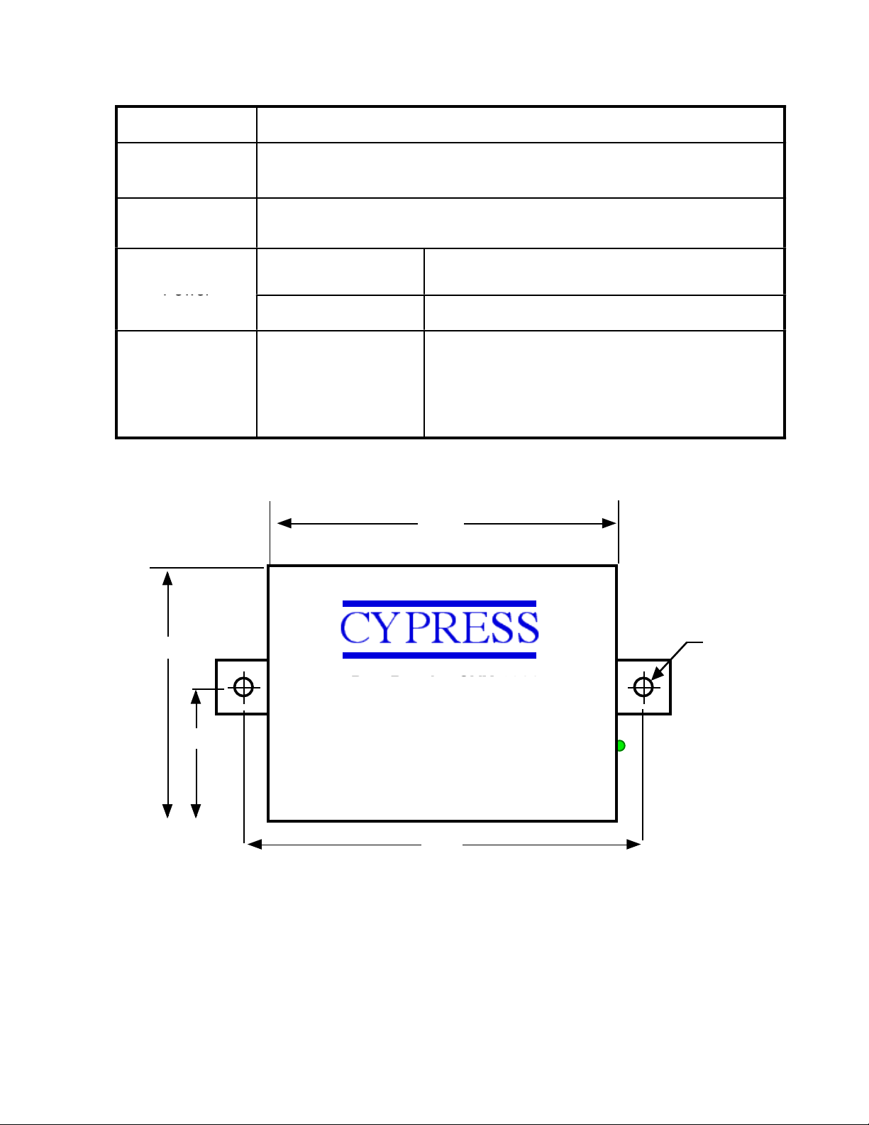
Aluminum Enclosure 3.5" x 2.75" x .75" each unit
Temp
Storage(-55˚C to + 150˚C)
Operating(-40˚C to +80˚C)
Humidity
95% (non-condensing)
Input
Unreg Input 8 to 16 VDC* @ 200mA Max
Power
Output
+5VDC @100mA
Data I/O
Interface
Reader 0- 30VDC
LED - 0 - 30VDC
Analog 0 - 5 VDC
3.3”
DataBender CVX-1300
2.8”
1.4”
3.65”
ø 0.15”
External Dimensions and Mounting Holes
Unit Height = 0.75”
Electrical and Mechanical Specifications
* See Rating Curve for Temperature and Power ratings
FCC Part 15 COMPLIANCE
This device complies with part 15 of the FCC Rules.
Operation is subject to the following two conditions:
(1) This device may not cause harmful interference, and
(2) this device must accept any interference received,
including interference that may cause undesired operation.
Page 2 of 7
Page 3

1
EXP-2000 Operation
The EXP-2000 can be utilized as an additional door and panel interface pair (Remote and Central) with an existing Suprex®
SPX-7400, SPX-7500. SPX-5600, or SPX-7200 system. Each EXP-2000 can be set to a unique address (1 through 15, see DIP
switch chart).
EXP Units used with a Cypress Suprex Gateway device will be set to the same address on both the Central and Remote sides of
the system.
SPX Systems:
The EXP-2000 is used with Suprex Gateway devices (SPX-7400/10 (FO), SPX-7500 (485), SPX-5600 (RF), SPX-7200(ET)) to
add Central and Remote pairs.
EXP-2000 Setup:
The DIP switch will be preset and labeled to determine whether the EXP-1000 will operate as a Wiegand Receiver (Remote) or
Wiegand Transmitter (Central).
Initialization of the EXP-2000:
1. Power off, Set DIP Switch #1 ON, All other DIP switches off
Set DIP Switch #3 OFF if using EXP-2000 with Suprex systems
2. Apply power to the EXP-2000.
The LED should illuminate with a solid Green indication.
3. Remove power and turn off all DIP Switches.
4. The unit is now initialized for usage with the appropriate system. Proceed to the following pages to set
DIP switches for address and Wiegand direction.
Setting EXP-2000 Addresses:
When using the EXP-2000 units with a Suprex gateway system, the Addresses must be set consecutively from 1 to the maximum
address to be used with the system. Most Suprex gateway systems will support a maximum of 8 devices
(refer to Gateway manual)
Example: An SPX-7400 system is to be setup with 4 pairs of EXP-2000 units.
The Addresses should be set: 1, 2, 3, 4 for the 4 pairs that will be used with the system and not 2,3,4,5 or 4,6,7,8 etc.
Page 3 of 7
Page 4

1
*
1234567
8
On
Off
EXP-2000 C Electrical Connections
J1
J2
2- 8 to 16 VDC In
1- Ground
8-RS485 (+)
7-RS485 (-)
6-+5 VDC Out
5-prog res 2
4-prog res 1
3-LED In
2-Data 1 out
1-Data 0 out
J1 Connections
2 - 8 to 16 VDC! Power IN (+)
1 - Ground! ! Power IN (-)
J2 Connections
8 - RS485 (+)!! RS-485 Input
7 - RS485 (-)! ! RS-485 Input
6 - +5 VDC OUT! 5 Volt Power out
5 - Analog 2! ! Analog Input #2
4 - Analog 1 ! ! Analog Input #1
3 - LED I/O! ! LED Signal Input/Output
2 - Data 1 Out! Wiegand Data 1 Output
1 - Data 0 Out! Wiegand Data 0 Output
EXP-2000
C
J3 Connections
12 - Relay #4!! N.O. Contact
11 - Relay #4!! Common
10 - Relay #4!! N.C. Contact
9 - Relay #3! ! N.O. Contact
8 - Relay #3! ! Common
7 - Relay #3! ! N.C. Contact
6 - RS232 Output! Serial Data OUT
5 - RS232 Input! Serial Data IN
4 - Ground! ! Wiegand/RS232 Ground
3 - Aux! ! Digital Output
2 - Relay # 2! ! Digital Input
1 - Relay # 1! ! Digital Input
12-R4 N.O.
11-R4 Com
10-R4 N.C
9-R3 N.O.
8-R3 Com
7-R3 N.C.
6-RS232 output
5-RS232 Input
4-Ground
3-Aux out
2-R2 in
1-R1 in
.
J3
Address settings for the EXP-2000
Cypress Suprex® systems will support different numbers
of additional EXP-2000 units depending upon the model
number. Refer to the specific documents for the
SPX-7400, SPX-5600, or SPX-7200 for maximum ratings.
Note:
To operate as a "Central" unit, DIP Switch #2 must be On.
Page 4 of 7
DIP Switch Address Settings
ADDRESS! ! SWITCH!
!!!12345678
1! ! ! 01000001
2! ! ! 01000010
3! ! ! 01000011
4! ! ! 01000100
5! ! ! 01000101
6! ! ! 01000110
7! ! ! 01000111
8! ! ! 01001000
9! ! ! 01001001
10! ! ! 01001010
11! ! ! 01001011
12! ! ! 01001100
13! ! ! 01001101
14! ! ! 01001110
15! ! ! 01001111!
16! ! ! 01010000
Page 5

1
1234567
8
On
Off
*
EXP-2000 R Electrical Connections
J1
J2
2- 8 to 16 VDC In
1- Ground
8-RS485 (+)
7-RS485 (-)
6-+5 VDC Out
5- R4 in
4- R3 in
3-LED out
2-Data 1 in
1-Data 0 in
J1 Connections
2 - 8 to 16 VDC! Power IN (+)
1 - Ground! ! Power IN (-)
J2 Connections
8 - RS485 (+)!! RS-485 Input
7 - RS485 (-)! ! RS-485 Input
6 - +5 VDC OUT! 5 Volt Power out
5 - Relay #4! ! Analog Input #4
4 - Relay # 3 ! Analog Input #3
3 - LED I/O! ! LED Signal Output
2 - Data 1 In! ! Wiegand Data 1 Input
1 - Data 0 In! ! Wiegand Data 0 Input
EXP-2000
R
.
12- R2 N.O.
11- R2 Com
10- R2 N.C
9- R1 N.O.
8- R1 Com
7- R1 N.C.
6-RS232 output
5-RS232 Input
4-Ground
3- Aux in
2- Not used
1 - Not used
J3
J3 Connections
12 - Relay #2!! N.O. Contact
11 - Relay #2!! Common
10 - Relay #2!! N.C. Contact
9 - Relay #1! ! N.O. Contact
8 - Relay #1! ! Common
7 - Relay #1! ! N.C. Contact
6 - RS232 Output! Serial Data OUT
5 - RS232 Input! Serial Data IN
4 - Ground! ! Wiegand/RS232 Ground
3 - Aux in! ! Digital Input
2 -! ! ! Not used
1 - ! ! ! Not used
Address settings for the EXP-2000
Cypress Suprex® systems will support different numbers
of additional EXP-2000 units depending upon the model
number. Refer to the specific documents for the
SPX-7400, SPX-5600, or SPX-7200 for maximum ratings.
Note:
To operate as a "Remote" unit, DIP Switch #2 must be Off.
Page 5 of 7
DIP Switch Address Settings
ADDRESS! ! SWITCH!
!!!12345678
1! ! ! 00000001
2! ! ! 00000010
3! ! ! 00000011
4! ! ! 00000100
5! ! ! 00000101
6! ! ! 00000110
7! ! ! 00000111
8! ! ! 00001000
9! ! ! 00001001
10! ! ! 00001010
11! ! ! 00001011
12! ! ! 00001100
13! ! ! 00001101
14! ! ! 00001110
15! ! ! 00001111!
16! ! ! 00010000
Page 6

1
810121416805535-40
Ambient Temperature
(Degrees Celsius)
Supply Voltage
Temperature/Voltage de-rating curve
Electrical and Environmental Specifications
The EXP-1000 units should be operated with a filtered 12 Volt nominal DC supply.
Any voltage between 8 and 16 volts can be utilized by following the temperature /voltage derating
curve. Voltage should not exceed 16 VDC under normal operating conditions.
Page 6 of 7
Page 7

1
1- D0 I/O
*
CYPRESS
*
CYPRESS
SPX to EXP-2000 Connections
8- EXP(+)
7- EXP(-)
6- +5VDC Out
5- Analog IN2
4- Analog IN1
3- LED I/O
2- D1 I/O
8-RS485 (+)
7-RS485 (-)
6-+5 VDC Out
5-Analog 2
4-Analog 1
3-LED I/O
2-Data 1 I/O
1-Data 0 I/O
SPX
EXP-2000
Page 7 of 7
8-RS485 (+)
7-RS485 (-)
6-+5 VDC Out
5-Analog 2
4-Analog 1
3-LED I/O
2-Data 1 I/O
1-Data 0 I/O
EXP-2000
 Loading...