

Page 1
Instruction Manual for the
E-SL 1200 / E-S 1202 Series
Manufactured by
Featuring
Page 2

CE DECLARATION OF CONFORMITY OF MACHINES
(Directive 89/392/EEC, Annex II, Part B)
Manufacturer: FAAC S.p.A.
Address: Via Benini, 1 – 40069 Zola Predosa Bologna – Italy
Declares that: Domoglide A.K.A. Estate Swing (USA) mod operator
• Is built to be integrated into a machine or to be assembled with other machinery to create a machine under the provisions
of Directive 89/392/EEC, and subsequent amendments 91/368/EEC, 93/44/EEC.
• Conforms to the essential safety requirements of the following EEC directives:
Bologna, January 1, 2002
Managing Director
A. Bassi
o 73/23/EEC and subsequent amendment 93/68/EEC, 89/336/EEC and subsequent amendment 92/31/EEC and
93/68/EEC.
o And also declares the it is prohibited to put into service the machinery until the machine in which it will be
integrated or of which it will become a component has been identified and declared as conforming to the
conditions of Directive 89/392/EEC and subsequent amendments assimilated under national laws under DPR
#459 of July 24, 1996.
A
bassi
Warnings for the installer
General safety obligations
1. Attention! To ensure the safety of people, it is important that you read all the following instructions. Incorrect installation or incorrect
use of the product could cause serious harm to people.
2. Carefully read the instructions before beginning to install the product.
3. Store these instructions for future reference.
4. This product was designed and built strictly for the use indicated in the documentation. Any other use, not expressly indicated here,
could compromise the good condition/operation of the product and/or be a source of danger.
5. FAAC declines all liability caused by improper use or use other than that for which automated system was intended.
6. Do not install the equipment in an explosive atmosphere; the presence of inflammable gas or fumes is a serious danger to safety.
7. The mechanical parts must conform to the provisions of Standards EN 12604 and EN 12605.
For non-EU countries, to obtain an adequate level of safety, the standards mentioned above must be observed, in addition to national
legal regulations.
8. FAAC is not responsible for failure to observe Good Technique in the construction of the closing elements to be motorized, of for any
deformation that may occur during use.
9. The installation must conform to Standards EN 12453 and EN 12445.
The safety level of the automated system must be C+D.
10. Before attempting any job on the system, cut out electrical power and disconnect the batteries.
11. The main power supply of the automated system must be fitted with an all-pole switch with contact opening distance of 3 mm or
greater. Use of a 6A thermal breaker will all-pole circuit break is recommended.
12. Make sure that a differential switch with threshold of 0.03 A is fitted upstream of the system.
13. Make sure that the earthing system is perfectly constructed, and connect metal parts of the means of the closure to it.
14. The automated system is supplied with an intrinsic anti-crushing safety device consisting of a torque control. Nevertheless, its tripping
threshold must be checked as specified in the Standards indicated at point 10.
15. The safety devices (EN 12978 standard) protect any danger areas against mechanical movement risks, such as crushing, dragging, and
shearing.
16. Use of at least one indicator-light (e.g. FAACLIGHT 12VDC) is recommended for every system, as well as a warning sign adequately
secured to the frame structure, in addition to the devices mentioned at point “15”.
17. FAAC declines all liability as concerns safety and efficient operation of the automated system, is system components not produced by
FAAC are used.
18. For maintenance, strictly use original parts by FAAC.
19. Do not in any way modify the components of the automated system.
20. The installer shall supply all information concerning manual operation of the system in case of an emergency, and shall hand over to
the user the warnings handbook supplied with the product.
21. Do not allow children or adults to stay near the product while it is operating.
22. Keep remote controls or other pulse generators away from children, to prevent the automated system from being activated involuntarily.
23. Transit through the leaves is allowed only when the gate is fully open.
24. The user must not attempt any kind of repair or direct action whatever and contact qualified personnel only.
25. Do not short-circuit the poles of the batteries and do not try to recharge the batteries with power supply units other than Master or Slave
cards.
26. Do not throw exhausted batteries into containers for other waste but dispose them in the appropriate containers to enable them to be
recycled.
27. Anything not expressly specified in these instructions is not permitted.
Page 3
Estate Slide Summery of Functions
The Estate Slide is only to be used for vehicular Slide gates in a Class I
setting.
Class I: A vehicular gate opener (or system) intended for use in a home of
one-to-four single family dwelling, or a garage or parking area associated
therewith.
The FAAC Estate Slide automated system was designed and built for controlling
vehicle access. Do not use for any other purpose.
The EstateSlide automated system automates residential Slide-leaf gates with
leaves of up to 16’ in length.
It consists of a locking electro-mechanical linear operator, powered by a 12V DC
battery, coupled with control board recharging the battery. The MASTER card can
be programmed and is used to set the following: function logics, work times (by
self-learning) and pause times, leaf speed, and the sensitivity of the anti-crushing
device.
The locking system will automatically lock when the motor is not operating. A release system enables the gate to be moved by hand in case of a system failure.
Keep this manual safely stored after
installation.
Serial Number__________________________
Date of Purchase_______________________
Place of Purchase______________________
Have this information on hand while handling all
service and warranty issues.
This manual and its contents are produced by Web Direct Brands, Inc. and is based on the instructions
written by FAAC,
Page 4
The table of contents are listed to assist you locating a desired section. We do
however strongly suggest studying every page of the instruction manual before
attempting installation.
PAGE(S):
• Specifications of the Estate Slide and Components 1.1
• System Overview & Preliminary Checks 2.1
Table of Contents
• Tools Needed for Installation 3.1
• IMPORTANT: Charging Battery Prior to Use 4.1
• Manual Operation 5.1
• Installation of Base, Operator and Limits 6.1-.4
• Control Board Layout 7.1
• Power 8.1
• Control Board Pre-Learning Preparations 9.1
• One Touch EZ Programming 10.1
• Programming Gate Movement Variables 11.1
ie. auto close, speed, force, delays
• Gate Movement Variables LED Chart 12.1
• Logic Summaries and Flow Charts 13.1-.2
• Accessory Terminals 14.1-.2
• Simple Diagnostics 15.1
• Photocell & Safety Device Guide 16.1-.2
• Installing the FAAC Receiver and Transmitter 17.1
• Warranty Notice 18
Marks pages with opener or usage warnings. Although we have marked these as very important warnings, please
read the entire manual. Every step is important to the correct installation of your gate opener.
Page 5
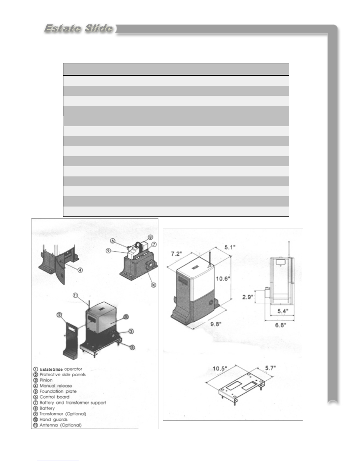
MODEL Estate Swing
Power Supply
Specifications
Rated Absorbed Power (W)
Max Static Force (N)
Load-free linear speed (in./sec.)
Use frequency (cycles/hour)
Consecutive cycles on charged battery
Battery recharge time
Operating ambient temperature
Operator weight (lbs)
Protection class
Gate leaf max length (ft.)
Gate leaf max weight (lbs.)
Operator overall dimensions LxHxD(in.)
Length of operator power cable (ft.)
115V AC/ 12V DC
48
560
10
5
Max. 15
10 min. for each full cycle
-4 to 131 Deg F
4.85
IP 44
Up to 12
Up to 550
See below
2.3
1.1
Page 6
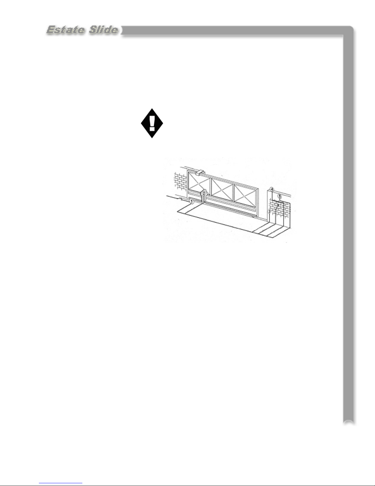
Standard System
Overview and Safety
Zones
The system display to the right is a
recommended standard system.
Other approved accessories can be
installed. Photo sensors and a flashing light indicating gate movement
is recommended for safety purposes.
1 Estate Swing Operator
2 Photocells (not included)
3 Key operated pushbutton
4 Flashing lamp
5 Radio receiver (optional)
Notes: 1) Do not extend operator connection cables
2) When laying electrical cables, use
appropriate rigid and/or flexible tube
3) Do not run any wires in the same conduit as
110 AC power that may be in the area. This
will cause unwanted interference
IMPORTANT
Preliminary Checks:
To ensure safety and an efficiently operating automated system, make sure the following conditions are observed.
• The gate and post must be suitable for being automated. Check that the structure is suffi-
ciently strong and rigid, and its dimensions and weights conform to those
indicated on page 1. In particular, wheel diameter must be in relation to the weight of the
gate to be automated. Dimensions and weight must match those indicated in the technical
specifications.
• Make sure the leaves move smoothly without any irregular friction during entire travel.
• The soil must permit sufficient stability for the expansion plugs securing the foundation
plate.
• Check if the upper guide and travel limit mechanical stops are installed.
We advise you to have any metalwork carried out before the automated system is installed.
2.1
Page 7
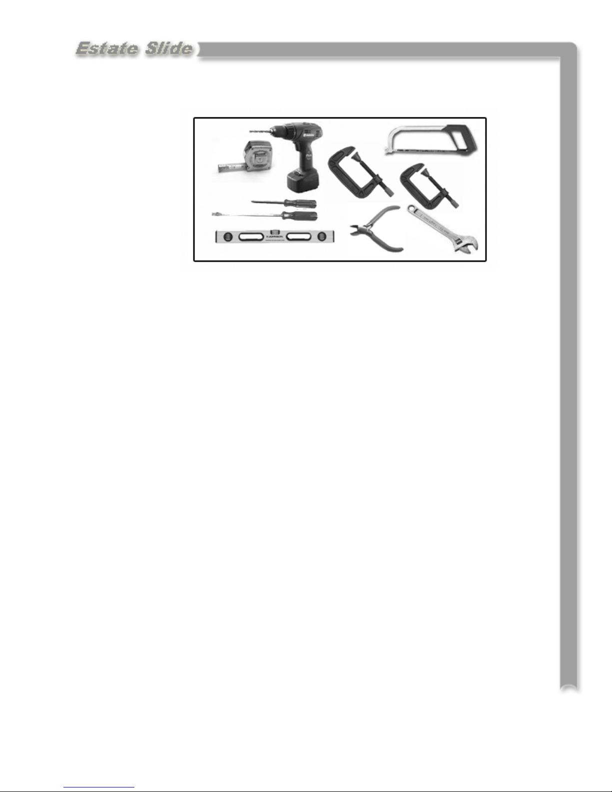
Tools Needed
• Power Drill
• Crescent Wrench
• 3/8” Drill Bit
• Hacksaw
• Flat Head Screwdriver
• Phillips Head Screwdriver
• Tape Measure
• Level
• Wire Strippers
• C-clamps
Other items that may be needed prior to commencing installation.
• Additional low voltage wire may be required to run power to your operator.
Length is determined by distance between transformer power supply and the
control box.
• If the gate is more than 1000’ from an a/c power supply then alternate power will
be necessary to charge your battery.
• Depending on the current base, you may need cement to form a level mounting
pad.
• A voltage meter may be necessary to run diagnostic checks.
• A digital camera will come in handy with technicians if any support is needed.
3.1
Page 8
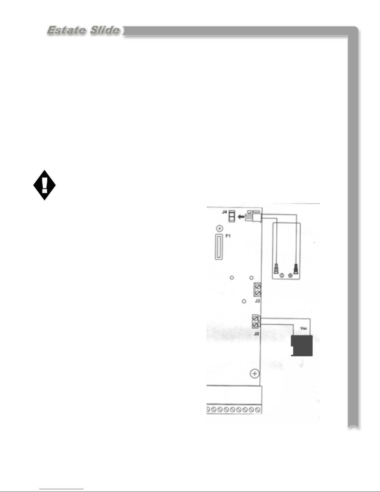
IMPORTANT: Charging Battery Prior to Use
Before beginning any electrical stages of installation we highly recommend charging the battery on the control board for 12 hours. This can be done anywhere there
is an outlet available.
1. Plug the battery into the control board (fig 1). For charging purposes it is not
necessary to hook the receiver to the battery or control board.
2. Insert the wires from the supplied AC transformer into terminal J2 of the con-
trol board. NEVER RUN 110V AC or POWER IN THROUGH ANY
OTHER METHOD BESIDES THE PROVIDED TRANSFORMER TO
THE CONTROL BOARD.
3. Let the unit charge for 12 hours, after you
can proceed with the installation
process.
Fig 1
12V
4.1
Page 9
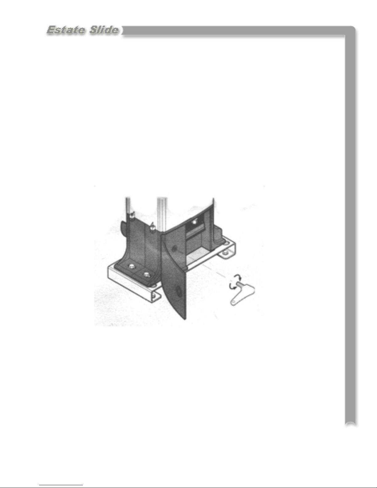
Manual Operation
1. Open the protective door by turning the slotted lock with a coin of large flat
head screw drive.
2. Take the supplied key located inside the door, fit it in the release system and turn
it clockwise until it reaches the mechanical stop.
3. Open or close the gate manually.
5.1
Page 10

Installation of Mounting Hardware
Set the Foundation Plate
1. Fit the 4 supplied caged nuts, as shown below, in the 4 square holes of the plate.
2. The foundation plate must be located as shown in example A (right closing) or example B
(left closing) to ensure the rack and pinion mesh correctly.
3. Secure the foundation plate to the floor, using adequate expansion plugs (below) and provide
one or more sheaths for routing the electrical cables. Using a level, check if the plate is perfectly level.
A B
6.1
Page 11

4. Lay the electric cables for connection to the accessories and power supply. To facilitate mak-
ing connections, allow the cables to project by about 8 inches from the hole of the foundation
plate.
Operator Installation
1. Position the operator on the plate using the supplied screws as shown below.
3. Secure the operator to the foundation plate, tightening the screws as shown below.
4. Prepare the operator for the manual operating mode as described in section 5
6.2
Page 12

Rack Installation
1. Manually take the leaf to its close position.
2. Lay the first piece of rack at the appropriate level and mark the hole position on the gate.
Make a hole and use nuts, bolts and washers to make a connection to the gate (not provided).
The holes in the rack are made oblong for adjustment after the holes are drilled. No special
bolts are required for mounting, simply tightening the bolts will hold the rack secure.
3. Move the gate manually, checking if the rack is resting on the pinion. Repeat at each hole.
4. Bring another rack element near the previous one, using a piece of rack (as shown below) to
synchronize the teeth of the two elements.
5. Move the gate manually and carry out the secur-
ing operations as far as the first element, proceeding until the gate is fully covered.
Notes on rack installation
• Make sure that during the gate travel, all the rack elements mesh correctly with the pinion.
• Do not, on any account, weld the rack elements either to the spacers or to each other.
• When you have finished installing the rack, adjust the distance between the pinion teeth and
the rack groove. Check if the distance is .06” (below) along the entire travel using the rack
slots.
• Manually check if the gate habitually reaches the travel limit mechanical stops and make sure
that there is no friction during gate travel.
• Do not use grease or other lubricants between rack and pinion.
6.3
Page 13

Travel Limit Magnet Installation
The ESTATE SLIDE operator is supplied with a sensor, by detecting the transit of two magnets
secured to the top of the rack, commands gate movement to stop.
1. Position the magnets on the rack as shown in below.
2. Power up the control board and enter the diagnostic mode (chapter 10)
3. Manually take the gate to the open position, but allow
a space of 2 cm from the travel limit mechanical stop
position. Slide the magnet on the rack until you see
that LED 1 on the control board goes off. Tighten the
magnet’s securing screws.
4. Manually take the gate to the closed position, but allow a space of 2 cm from the travel limit mechanical
stop position. Slide the magnet on the rack until you
see that LED 1 on the control board goes off.
Tighten the magnet’s securing screws.
5. Re-lock the operator.
6.4
Page 14

Control Board Layouts
ATTENTION: Study the control board and read this section
thoroughly before attempting to operate your gate opener.
Warnings:
• Before attempting any job on the control board (connections, maintenance), turn
off electrical power and unplug the support battery.
• Install a surge protector upstream of your opener, the opener is not power surge
proof nor will power surge damage be covered under warrantee.
• Always separate power from control and safety cables (push-buttons, receivers,
photocells, etc.). To avoid any electrical noise, use separate sheaths or a shielded
cable (with earthed shield).
Layout of Control Board
LED Programming LEDs
P Power ON and diagnostics LED
P1 “Function” programming push-button
P2 “Value” programming push-button
F1 Battery and motor fuse - F15A
J1 Accessories Terminal board
J2 Transformer Terminal board
J3 Motor connection terminal
J4 Battery connector
J5 Minidec connector/RP receiver
J10 Sensor Terminal Board
7.1
Page 15

Power
1. The Estate Slide comes with 1) AC transformer. If the AC transformer supplied has 4
screw terminals, use the center 2 terminals to attach your low voltage wire (polarity is
not relevant). You may locate the transformer up to 1000’ away from the control
board with 16 gauge or larger direct burial low voltage wire.
2. Insert the two wires into the power in section on the control board (J2) on the master
board. The wires are interchangeable and do not have a positive and negative. Do not
splice the power cable wire.
Never run 110VAC power directly to the Estate Swing. This will destroy the Estate Slide control board.
3. Before plugging in your transformer, plug the battery into the control
board. The clear plastic clip gets clipped
into J4 with the clip side on the left. The
other side of the battery wire has a clear
plastic disconnect that slides on the battery
terminals. Red to Red, Black to Black. Re-
versing the wires will blow the fuse.
Never connect the power wire with the
transformer plugged in. Contact between
the two lead wires, even for a second, will
destroy the transformer.
4. Plug the transformer into a 110 V AC
outlet.
5. The transformer is not weather proof
and must be kept in a covered area. Plug
covers are available from your dealer,
contact 1-800-640-GATE for a dealer in
your area.
6. The power light (P) will be on if the
power and battery are connected properly.
If the power light is blinking slowly then
only the battery is connected, check your
power
connections.
8.1
Page 16

Control Board Pre-Learning Preparations
For your opener to function properly a few connections must be made prior to the learning
process. Accessories should NOT be installed until after the learning process is completed.
1. Using the provided orange jumper wire, connect the normally closed safety terminals
(terminals 3, 4, and 5) to one of the negative terminals (terminals 12, 13, 14, or 15). We
recommend that these jumpers are later replaced with safety devices after learning is complete.
2. Connect the power last. First connect the battery to the control board and then connect
the power supply to J2 on the control board.
3. Your connections can be checked using the diagnostics mode. Press P2 once. On a
single gate opener operation C, D, and E should be lit. After checking press P2 again to
exit the diagnostics mode. To learn more about diagnostics see section 2.
9.1
Page 17

NOTE: Before beginning the one touch learning procedure be sure to have the limit magnets
set up. These will let your gate know where to stop during the learning process.
Enter Learning Mode
Enter the programming mode by
pressing P1 6 times until all 5
LEDs (A,B,C,D,E) are lit. This is
the learning mode.
Programming
While the 5 function LEDs
(A,B,C,D,E in picture) are lit
steadily, briefly press (about 1
second) the P2 button.
The operator or operators start
the opening maneuver, and the
function LEDs begin flashing.
Wait for the operator or operators to reach the opening stops. The learning procedure has finished. Press P1 once more to exit
the learning mode before attempting to operate the opener.
You may now test your gate opener or continue on with changes to the factory speed, force,
delay settings. To test your opener, briefly touch a wire from terminal 1 to one of the
negative terminals (12, 13, 14, or 15).
10.1
Page 18

Programming Gate Movement Variables
Using the following procedures you can change factory settings such as auto
close, speed, force, delays and more.
Begin the programming process by
pressing P1. Pressing P1 selects
A,B,C,D or E. A, B, C, D and E correspond with the variables in the chart on
the following page.
When you are on the desired variable
you would like to change the setting of
press P2 to change the setting of that
variable. P2 will change the light to 1,
2, 3 or 4 which correspond with the settings on the chart below on the following page. Below is a list what each variable controls.
A: Switches between Function Logics. Function Logics are sets of actions that will occur
when an accessory terminal connection is made or disrupted. Each set of actions is designed to give different results providing increased safety, convenience or other.
B: Switches between the amount of time the gate pauses before closing after reaching full
open. By selecting Logic EP (4) all pause times will be void and the gate will remain open
until an opening devices is triggered.
C: Adjusts the partial opening width.
D: Switches between the amount of force the gate opener will exert before an obstruction is
detected and the gate reverses directions.
E: Switches between the speed of the gate motion. This does not effect the soft start and
stop.
See the following page for Gate Movement Variables LED Chart .
11.1
Page 19

Gate Movement Variables LED Chart
Variable LED Definitions
Function
LED
A
B
C
Function
Function Logic — Logic flow chart found on page 18,19
1= A (Automatic - automatically closes the gate depending on the
set pause time. It is the most common setting)
2= S (Safety - designed for higher control and accelerated levels of
safety, also automatically closes the gate)
3= AP (Stepped Automatic - is very similar to automatic (A) but
has a higher amount of safety. It has an increased amount
of motion stop points.)
4= EP (Stepped Semi-automatic - is designed to function similar to
a garage door opener. Turns off the auto close setting.)
Pause Times
1= 5 Seconds
2= 10 Seconds
3= 20 Seconds
4= 30 Seconds
Partial Opening Width
1= 90 cm
2= 120 cm
3= 150 cm
4= 180 cm
Static Force
1= Low
D
E
• Pressing P1 moves you through the Letter LEDs
2= Medium Low
3= Medium High
4= High
Speed
1= Low
2= Medium Low
3= Medium High
4= High
• After switching to the desired Letter LED, Pressing P2 moves you
through the Number LEDs
12.1
Page 20

Logic Summaries and Flow Charts
Logic A - Logic A (automatic) is the most common setting. It automatically closes the gate depending on the set pause time. This logic must be used in conjunction with the accessories: Free
Exit Sensor and Gate Timer.
Gate Status Result of Terminal
1 activation
Closed
Open and in
pause before
re-closing
Closing
Opening
Stopped in mid
cycle
Opens leaf and re-closes after pause time No effect
Re-loads pause time No effect Re-loads pause time
Re-opens leaf No effect Stops motion and
Closes the leaf No effect
Result of Terminal
2 activation
No effect Reverses direction
Result of Terminal
4 interruption
of motion
Result of Terminal
5 interruption
reverses direction
after interruption
No effect
Logic S - Logic S (safety) is designed for higher control and accelerated levels of safety. By triggering an opening device (i.e. push button, transmitter) the gate reverses directions preventing
foreseeable accidents.
Gate Status Result of Terminal
1 activation
Result of Terminal
2 activation
Result of Terminal
4 interruption
Result of Terminal
5 interruption
Closed
Open and in
pause before
re-closing
Closing
Opening
Stopped in mid
cycle
Opens leaf and re-closes after pause time No effect
Re-closes the leaf No effect Closes after 5 sec-
Re-opens the leaf No effect Reverses direction of
Re-closes the leaf Reverses direction
onds
motion
No effect
of motion
Closes the leaf No effect
13.1
Page 21

Logic Summaries and Flow Charts (cont)
Logic AP - Logic AP (stepped automatic) is very similar to automatic (A) but has a higher
amount of safety. It has an increased amount of motion stop points.
Gate Status Result of Terminal
1 activation
Closed
Open and in
pause before
re-closing
Closing
Opening
Stopped in mid
cycle
Opens leaf and re-closes after pause time No effect
Stops operation No effect Re-loads pause time
Re-opens leaf No effect Reverses direction of
Stops operation Stops motion and
Closes the leaf No effect
Result of Terminal
2 activation
Result of Terminal
4 interruption
reverses direction
after interruption
Result of Terminal
5 interruption
motion
No effect
Logic EP - Logic EP (stepped semi-automatic) is designed to function similar to a garage door
opener. At full open the gate does not re-close after a pause time, it stays open until triggered to
re-close. Logic EP over-rides any set pause time.
Gate Status Result of Terminal
1 activation
Result of Terminal
2 activation
Result of Terminal
4 interruption
Result of Terminal
5 interruption
Closed
Open and in
pause before
re-closing
Closing
Opening
Stopped in mid
cycle
Restarts motion in opposite direction the
gate was previously moving before
Re-closes the leaf
stopped in mid cycle
Opens leaf No effect
No effect
Stops operation No effect Reverses direction of
motion
Stops operation Reverses direction
of motion
No effect
No effect
13.2
Page 22

Accessory Terminals
READ prior to attempting to operate the arm. Normally Closed connections must
be made for proper gate opener function. The full accessory board is only found on
the master control board. The slave control board only contain one Normally Open
J1—Terminal Board for Master Card
Terminals
1 - “Open/Close Function” This is a normally open terminal where by any device (i.e. push
button, keypad, receiver) which, by closing a contact, provides an opening and/or closing pulse for both gate leaves (if there is only one leaf, it will control the one leaf).
2 - “Single Leaf Open/Close Function” This is a normally open terminal where by any de-
vice (i.e. push button, keypad, receiver) which, by closing a contact, provides an opening and/or closing pulse for only the gate leaf controlled by the master control board
(if there is only one leaf, it will control the one leaf).
3 - “Stop Command” This is a normally closed terminal where by any device (i.e. push
button) which, by opening a contact, halts gate movement. IMPORTANT: If a connec-
tion is not made from this terminal to one of the - (negative) terminals (i.e. 12, 13, 14,
15) gate motion will not commence.
14.1
Page 23

J1—Terminal Board for Master Card (cont.)
Terminals (cont.)
4 - “Opening Safety Device” This is a normally closed terminal where by any device (i.e.
photocells, sensitive edge, magnetic loops) which, if there is an obstacle in the area they
protect during opening, reverses gate direction to closing.
If the opening safety devices are tripped when the gate is closed, they prevent the leaf
movement.
IMPORTANT: If a connection is not made from this terminal to one of the - (negative)
terminals (i.e. 12, 13, 14, 15) gate opening will not commence.
5 - “Closing Safety Device” This is a normally closed terminal where by any device
(i.e. photocells, sensitive edge, magnetic loops) which, if there is an obstacle in the
area they protect during closing, reverses gate direction to opening.
If the closing safety devices are tripped when the gate is open, they prevent the leaf
movement.
IMPORTANT: If a connection is not made from this terminal to one of the (negative) terminals (i.e. 12, 13, 14, 15) gate closing will not commence..
6 - N/A
7, 8 - “Positive 24 Voltage” Positive 24V for powering accessories that are run by 24V
DC power (i.e. locks, safety devices).
9 - “Indicator Light” When used with terminal 11, this terminal powers and operates the
indicator light. To avoid compromising correct operation of the system, do not ex-
ceed the indicated power (12V .5Wmax). The indicator light is lit during open,
opening and blocked. The indicator is flashing during closing.
10 - “Lamp” When used with terminal 11 , this terminal powers and operates the
flashing lamp output. To avoid compromising correct operation of the system, do
not exceed the indicated power (12V 21Wmax).
11 - “Positive 12 Voltage” This is a 12V terminal used to power the indicator light, lamp
and devices controlled by 12V DC.
12, 13, 14 ,15 - “Negatives” Interchangeable negative terminals for use with powered ac-
cessories, safety devices and opening devices.
14.2
Page 24

Simple Diagnostics
Diagnostics using the Power
light on your Master Control
Board.
The P light has a diagnostic function. There are 4 statuses.
1. Steady light indicating main
power is ON and
the battery is charged
2. Flashing slowly (lights every second) indicates no main power but the battery is charged.
3. Flashing quickly (lights every 1/4 of a second) indicates main power on but discharged battery
4. Light OFF indicates no main power and discharged battery.
Status of accessory inputs.
The Master Control Board has the ability to verify the status of the terminal board inputs. To access this function:
When all LEDs are off (both lettered and numbered) press P2. The statuses of the accessory terminals in the following chart will be shown in the lettered LEDs column.
LED ON =
Closed Contact
LED OFF =
Open Contact
When you have
finished checking,
press P2 again to
exit.
If you do not, the
LED status check
will stay active for
5 minutes and then
the board returns
to all LEDs OFF.
WARNING:
When you access
the input status
function all accessories are powered, even with the gate idle. P1 is active and can be used to open and close
the gate.
Normal Operation
idle LED lights
A = OFF A = Terminal 1,
B = OFF B = Terminal 2,
C = ON C = Terminal 3,
D = ON D = Terminal 4,
E = ON E = Terminal 5,
1 = OFF if closed or
open, ON if not
LED ON OFF
Open/close function
Single leaf open/
close
Stop Command
Opening safety device
Closing safety device
1 = Sensor
Opening/closing
device is triggered.
Opening/closing
device is triggered.
Motion stop device is
in place and not
triggered or jumper is
in place..
Motion stop device is
in place and not
triggered or jumper is
in place.
Motion stop device is
in place and not
triggered or jumper is
in place..
Sensor is not tripped. Sensor is tripped.
Opening/Closing
device is not trig-
gered.
Opening/Closing
device is not trig-
gered.
Motion stop device
has been triggered or
is not connected.
Safety device has
been triggered or is
not connected.
Safety device has
been triggered or is
not connected.
15.1
Page 25

Photocell & Safety Device Guide
Before connecting the photocells (or other devices) we advise you to select the type
of operation according to the movement zone to be protected.
Opening Safety Devices: They operate only during the gate opening movement and,
therefore, they are suitable for protecting the zone between the opening leaves and
fixed obstacles (walls, etc.) against the risk of impact and crushing.
Closing Safety Devices: They operate only during the gate closing movement and,
therefore, are suitable for protecting the closing zone against the risk of impact.
Opening/Closing Safety Devices: the operate during the gate opening and closing
movements and, therefore, they are suitable for protecting the opening and closing zones
against the risk of impact.
If one or more devices have the same function (opening or closing) they must be
connected to each other in series. Normally Closed contacts on the accessories
panel must be used.
Examples of common wiring layouts
Continued on next page
16.1
Page 26

16.2
Page 27

Installing and Setting FAAC Transmitters and Receivers
Installing the Receiver
1) Locate the 5 Silver Pins on
your MASTER Estate Swing
board, located above the battery; with power and battery
OFF
2) Locate the white connector on
the receiver.
3) Push the white connector from
the receiver on the 5 pins on
your FAAC board with the dip
switches of the receiver board
facing the center of the Estate
Swing board.
1) Set the dip switches 1-12 on the receiver by switching
Record this dip switch combination
2) Slide off the battery cover of the transmitter (located at
3) Set the dip switches in the transmitter to the same settings as the
dip switches on the receiver.
4) Repeat this for all of the transmitters.
Setting the Dip Switches
them in the up or down position.
the bottom front cover)
17.1
Page 28

If you call in for technical support or warranty
support: before any control board or motor will be
permitted to be sent in for testing or warranty you will
be required to e-mail digital photos to the technician.
This is done in your best interest to save unnecessary shipping expenses and time lost. Many
times we can come up with solutions to issues by seeing pictures that relay information that is
impossible to relay through a phone conversation.
Below are examples of control board pictures and motor pictures that we will be looking for:
18
 Loading...