

Page 1
E721
E721
/ SAFE
/ SAFE
< (1)
BUS
2EASY
< (2)
< OPEN A
< GND
< OPEN B / CLOSE
/ SAFE
<STOP
<FSWOP
< GND
<FSWCL
<+24
(PE-N-L)
< MAIN
TRANS
<PRIM
/ SAFE
F
-
RADIO XF
F
< SEC
TRANS
F
< BATTERY
<M
OR
OT
<L
FCC
AMP
FCA
RADIO1
< LOCK
RADIO2
RELEASE
< LOCK
ERROR
POWER
TTERY
BA
<LOCK
+
SETUP
USB
OUT
-+
Page 2
CONTENTS
1 WARNINGS ..................................................................................................................................................... 2
2 LAYOUT AND COMPONENTS ...........................................................................................................................2
2.1 COMPONENT DESCRI PTION ...................................................................................................................................... 3
2.2 DESCRIPTI ON OF TERMIN AL BLOCK J13 .................................................................................................................... 3
3 TECHNICAL SPECIFICATIONS .......................................................................................................................... 3
4 ELECTRIC CONNECTIONS ............................................................................................................................... 4
4.1 BUS-2EASY PHOTOCELLS ............................................................................................................................................ 5
4.1.1 ADDRESSING BUS-2EASY PHOTOCELLS ..........................................................................................................................5
4.1.2 STORING BUS-2EASY ACCESSORIES .............................................................................................................................5
4.2 TRADITIONAL PHOTOCELLS ....................................................................................................................................... 5
4.3 SAFE IN PUT CONNECTIONS
5 PROGRAMMING ............................................................................................................................................8
5.1 1st LEVEL PROGR AMMI NG ........................................................................................................................................ 8
nd
5.2 2
LEVEL PROGR AMMI NG ...................................................................................................................................... 10
6 STORING RADIO CODE ................................................................................................................................ 12
6.1 STORING DS RADIOCON TROLS ............................................................................................................................... 12
6.2 STORING SLH RADIOCONTROLS ............................................................................................................................. 13
6.3 STORING LC/RC RADIOCONTROLS (ONLY FOR SOME MA RKETS) ............................................................................ 13
6.3.1 STORING LC/RC RADIOCONTROLS REMOTELY ...........................................................................................................13
6.4 RADIOCONTROLS DELETION PROCEDURE .............................................................................................................. 13
7 OPERATIONAL START-UP ............................................................................................................................... 14
7.1
CHECKING THE LEDS ................................................................................................................................................ 14
7.2 BATTERY OPERATION
7.3 POSITION ING LIMIT S WITCHES ....................................................................................................................................
7.4 MASTER / SLAVE CONFIGURATIONS ......................................................................................................................... 16
7.4.1 MASTER / SLAVE WIRING ............................................................................................................................................
7.4.2 MASTER/SLAVE SETUP PROCEDURE .............................................................................................................................
7.5 SETUP ....................................................................................................................................................................... 17
8 TESTING THE AUTOMATED SYSTEM ........................................................................................................... 17
9 ALARM AND ERROR SIGNALS .................................................................................................................. 17
9.1 ALARMS ................................................................................................................................................................... 17
9.2 ERRORS .................................................................................................................................................................. 17
10 FUNCTION LOGICS .................................................................................................................................... 18
.........................................................................................................................7
............................................................................................................................... 14
ENGLISH
16
16
CE DECLARATION OF CONFORMITY
Manufacturer: FAAC S.p.A.
Address: Via Calari, 10 - 40069 Zola Predosa BOLOGNA - ITALY
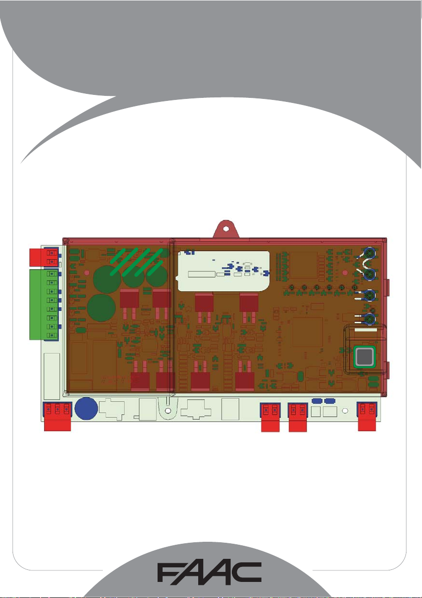
Declares that: Control board E721
• conforms to the essential safety requirements of the following EEC directives
2006/95/EC Low Voltage Directive
2004/108/EC Electromagnetic Compatibility Directive
Additional note:
This product has undergone testing in a typical
standard configuration (all products built by FAAC S.p.A. )
Bologna, 01-12-2010
The Managing Director
A. Marcellan
WARNINGS
• Attention! To ensure the safety of people, it is important that you read all the following instructions.
• Incorrect installation or incorrect use of the product could cause serious harm to people.
• Carefully read the instructions before beginning to install the product and keep for future reference.
• The symbol highlights notes that are important for personal safety and the protection of the automated
system.
• The symbol
calls your attention to notes on product specifications or operation.
1
Page 3
E721
SAFE
/ SAFE
1 WARNINGS
Before attempting any work on the control board (connections, maintenance), always turn off power.
Install, upstream of the system, a differential thermal breaker with adequate tripping threshold.
Connect the earth lead to the appropriate terminal.
Always separate power cables from control and safety cables
(push-button, receiver, photocells, etc.). To avoid any electric
noise, use separate sheaths or a shielded cable (with earthed
shield).
ENGLISH
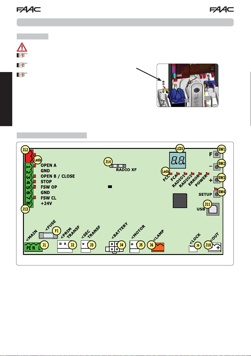
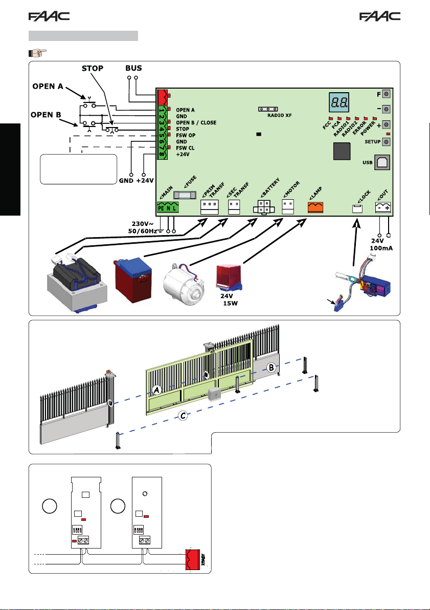
2 LAYOUT AND COMPONENTS
/
SAFE
/ SAFE
SENSOR
LIMIT SWITCH
Fig. 1
2
Page 4
2.1 COMPONENT DESCRIPTION
LCD SIGNALLING AND PROGRAMMING DISPLAY
SW1 PROGRAMMING PUSH-BUTTON "F".
SW2 PROGRAMMING PUSH-BUTTON "-".
SW3 PROGRAMMING PUSH-BUTTON "+".
SW4 “SETUP” PUSH-BUTTON
LEDs INPUTS STATUS CONTROL LED
J1 MAIN POWER SUPPLY CONNECTOR
J2 TRANSFORMER PRIMARY WINDING CONNECTOR
J3 TRANSFORMER SECONDARY WINDING CONNECTOR
J4 EMERGENCY BATTERY CONNECTOR (ACCESSORY)
J5 MOTOR CONNECTOR
J6 FLASHING LAMP CONNECTOR (24 V= - 15W)
MOTOR LOCK AND
J9
CONTACT
MOTOR RELEASE
CONNECTOR
J10 OUT OUTPUT CONNECTOR
J11 USB CONNECTOR FOR PC CONNECTION
J12 BUS-2EASY DEVICE CONNECTION CONNECTOR
J13 INPUT CONNECTOR IN CONNECTOR BLOCK
J14 RADIO RECEIVER MODULE CONNECTOR FOR OMNIDEC
LCD1 SIGNALLING AND PROGRAMMING DISPLAY
F1 PROTECTION FUSE
2.2 DESCRIPTION OF TERMINAL BLOCK J13
INPUT No DESCRIPTION
1 OPEN A Device with N.O. contact
2-6 GND Accessory power
3
(1)
4
(1)
OPEN B
(DEFAULT)
CLOSE
SAFE Device with N.C. contact
STOP
(DEFAULT)
SAFE Device with N.C. contact
5 FSW OP Device with N.C contact
7 FSW CL Device with N.C contact
8 +24 V= Accessory power supply
that causes total opening
of the gate
supply negative
Device with N.O. contact
that causes partial opening
of the gate
Device with
that causes the immediate
and complete reversal of
N.O.
that closes the gate
contact
the gate
Device with N.C. contact
that halts the gate
that causes the immediate
and complete reversal of
the gate
that reverses the motion
during gate opening
that reverses the motion
during gate closing
positive
3 TECHNICAL SPECIFICATIONS
Power supply 230 V~ 50 Hz
Power consumption
from mains stand-by
Motor max. load 10A
Accessory
power supply
Accessory
max. current
Environmental
temperature
Flashing lamp
load
Output load 24 V= - 100 mA (2)
Protection
fuses
Function
logics
Work time Programmable (from 0 to 10 min.)
Pause time
OPEN A / OPEN B
Motor power Adjustable over 50 levels
Opening-closing
motor speed
Connector Inputs/
Outputs
Inputs/Outputs in
terminal block
Programming
(1) The uses of inputs 3 and 4 can be set by
configuring the corresponding parameters
at programming level 2 (parameters Ob
and
to operate the automated system with the
chosen logics, please refer to the tables
featured at the end of this manual (Par.
10 - OPERATION LOGICS. As for the wiring
required using these SAFE configured
inputs, please refer to the diagrams shown
in Fig.12 and Fig. 13
(2) The output load must be considered
as already included in the max. current
available for the accessories
Semiautomatic, Semiautomatic “step“,
Automatic, Automatic “step”, Auto-
matic with timer function, Automatic
Safety devices, Automatic Safety devices
“step“, Automatic with reverse on pause,
Semiautomatic “b”, Mixed logic “bC ”,
Programmable (from 0 to 10 min.)
Power supply, Battery, Motor, Module
XF433/868,
BUS-2EASY, OPEN A, OPEN B/CLOSE/SAFE,
STOP/SAFE, GND, Opening and closing
photocells, +24 V=, Mains power supply,
Flasher, Electric release
1st and 2nd level with 3 keys (+, -, F) and
SP
). For the exact description on how
10 W
24 V=
24 V= max. 500 mA
BUS-2EASY max. 500 mA
(-20 - +55) °C
24 V= - 15 W
F1 = T1A - 250V~
Dead-man.
Adjustable over 10 levels
Motor lock electric release bat-
teries, Motor Lock,
USB
motor lock, OUT
display.
ENGLISH
3
Page 5
ON
1 2 3 4
BUSBUS
DL2
DL1
DS1
ON
1 2 3 4
BUSBUS
DL2
DS1
RX - TX
4 ELECTRIC CONNECTIONS
The wiring shown in Fig. 2 refers to the inputs of the board with DEFAULT configuration.
/ SAFE
/ SAFE
To connect the photocells
and safety devices, con-
sult paragraph 4.2
ENGLISH
(Locks the motor when
the motor release han-
=
A: Photocells that operate during CLOSING
B: Photocells that operate during OPENING
C: Photocells that operate during OPENING and CLOSING
MOTOR RELEASE
CONTACT
dle is operated)
=
Fig. 2
Fig. 4
RX TX
Fig. 3
Before connecting the photocells, it is advisable to select
the type of operation on the basis of the area of movement
that they need to protect:
Safety devices during closing: operate only during the
DL1 = Align-
ment
DL2 = BUS2EASY/Power
supply status
DS1 = Dipswitches for
programming
automated system closing movement and are therefore
suitable for protecting the closing area from the risk of
impact.
Safety devices during opening: operate only during
the automated system opening movement and are
therefore suitable for protecting the opening area from
the risk of impact.
Safety devices during opening/closing: operate during
both the automated system opening and closing
movements and are therefore suitable for protecting
the entire movement area from the risk of impact.
4
Page 6
OUT
OUT
OUT
4.1 BUS-2EASY PHOTOCELLS
This board is equipped with a BUS-2EASY circuit that can
be used to easily connect a high number of auxiliary BUS2EASY devices to the safety device (e.g. up to 16 pairs of
photocells), appropriately programmed, using only two
cables without polarity.
Before connecting the photocells, it is advisable to select
the type of operation (Fig. 3) on the basis of the area of
movement the cells must protect and to position the dip
switches on both the transmitter and receiver (see Fig. 4)
as in Tab. 1.
4.1.1 ADDRESSING BUS-2EASY PHOTOCELLS
It is important to give both the transmitter
and the receiver the same address.
Ensure that there are not two or more pho-
tocell pairs with the same address.
If no BUS-2EASY accessory is used, leave the
BUS-2EASY connector (J12 - fig. 1) free.
Tab. 1 - Addressing BUS-2EASY photocells
Dip1 Dip2 Dip3 Dip4 Re. Type
OFF OFF OFF OFF
OFF OFF OFF ON
OFF OFF ON OFF
OFF OFF ON ON
OFF ON ON OFF
OFF ON ON ON
ON OFF OFF OFF
ON OFF OFF ON
ON OFF ON OFF
ON OFF ON ON
ON ON OFF OFF
ON ON OFF ON
ON ON ON OFF
OFF ON OFF OFF
OFF ON OFF ON
ON ON ON ON / OPEN PULSE
C
4.1.2 STORING BUS-2EASY ACCESSORIES
At any time it is possible to add BUS-2EASY photocells
and accessories to the system, simply by following the
procedure below:
1. Install and programme the accessories with the
required address (see par. 4.1.1).
2. Cut off power to the board.
3. Connect both cables of the BUS-2EASY accessories to
the red terminal block J12 (polarity irrelevant).
4. Power the board.
5. Quickly press the SETUP push-button (SW4) once to
register the accessories. Check the operation of the
installed BUS-2EASY devices.
6. The board has stored the BUS-2EA SY accessories.
Follow the instructions in the following table to check that
the BUS-2EASY connection status is efficient.
B
A
OPENING
Max. 6 pairs
CLOSING
Max. 7 pairs
OPENING and
CLOSING
Max. 2 pairs
The same procedure must be performed on a
MASTER unit also when acquiring a SLAVE unit
connected to the BUS- 2EASY with POLARISED
connection
Tab. 2 - Description of BUS-2EASY LED
Fixed ON
Slow
flasher
Normal activity (LED on even without photocells). No registered photocell engaged.
At least one registered photocell engaged
or not aligned.
Off (flash
every
BUS-2EASY line short-circuited.
2.5 secs)
- BUS-2EASY line disabled (does not supply
Off
power)
- Battery operation
- Unit programmed as a SLAVE
4.2 TRADITIONAL PHOTOCELLS
Connection of 1 pair of closing photocells
with FAIL-SAFE safety device
activated
Set in second level of programming
o1 = 01
OUT
Other safety
devices
Connection of 1 pair of closing photocells
with FAIL-SAFE and STOP safety device
Other safety
devices
If the FAIL-SAFE safety device is
used, connect the power supply of the
transmitters to terminals 6 and 8 of J13.
If the FAIL-SAFE safety device is used, connect
the power supply of the transmitters to OUT
after setting it as appropriate (see 2nd
level programming and Fig. 5).
If the FAIL-SAFE safety device is used, even the
unused safety inputs must be connected via a
shunt lead to the negative of OUT (see Fig. 5).
5
deactivated
OUT
OUT
not
ENGLISH
Fig. 5
Page 7
Connection of a pair of opening photocells
Other safety
devices
Connection of a pair of closing photocells and a pair of
opening/closing photocells
Fig. 6
Connection of a pair of closing photocells and a pair of
opening photocells
ENGLISH
Connection of two pairs of closing photocells
Fig. 9
Connection of a pair of closing photocells, a pair of open-
ing photocells and a pair of opening/closing photocells
Fig. 7
Fig. 10
Connection of no safety and stop device
Fig. 8
Fig. 11
6
Page 8

4.3 SAFE INPUT CONNECTIONS
If the Fail Safe safety device is enabled (parameter that can be set in programming level 2), the negative
used for managing the SAFE input is - OUT (see Fig. 12).
Connection of a safety device (other safety devices) to the SAFE input with the FAIL SAFE function enabled
By setting: 2nd level
2nd level
Other safety
If the Fail Safe safety device is disabled (parameter that can be set in programming level 2), the negative
used for managing the SAFE input is - (see Fig. 13).
Connection of a safety device (other safety devices) to the SAFE input with the FAIL SAFE function disabled
By setting: 2nd level
2nd level
SP=01
devices
- OUT
SP=01
Other safety
devices
-
o1=01
(FAIL SAFE ENABLED)
(INPUT 4 = SAFETY EDGE SAFETY)
OPEN A
GND
OPEN B / CLOSE
SAFE
FSW OP
GND
FSW CL
+24V
o1=00
(FAIL SAFE DISABLED)
(INPUT 4 = SAFETY EDGE SAFETY)
OPEN A
GND
OPEN B / CLOSE
SAFE
FSW OP
GND
FSW CL
+24V
/ STOP
/ STOP
By setting: 2nd level
2nd level
Other safety
devices
- OUT
By setting: 2nd level
2nd level
Ob=02
Other safety
devices
-
o1=01
(FAIL SAFE ENABLED)
Ob=02
(INPUT 3 = SAFETY EDGE SAFETY)
OPEN A
GND
SAFE
STOP
FSW OP
GND
FSW CL
+24V
o1=00
(FAIL SAFE DISABLED)
(INPUT 3 = SAFETY EDGE SAFETY)
OPEN A
GND
SAFE
STOP
FSW OP
GND
FSW CL
+24V
/ OPEN B / CLOSE
/ OPEN B / CLOSE
ENGLISH
Fig. 12
Fig. 13
In case N.C. contact devices are not used (other safety devices) the SAFE input must be jumpered to -OUT
with FAIL SAFE enabled or to GND with FAIL SAFE disabled.
7
Page 9

5 PROGRAMMING
It is necessary to access PROGRAMMING mode in order
to program automated system operation.
Programming is divided in two parts: 1st LEVEL and 2nd
LEVEL.
The status of the automated system is
normally shown on the display. When
push-button F is pressed or when F and
+ are pressed simultaneously, this gives
access to 1st or 2nd level programming.
During battery operation the display is off.
Briefly press “+” to view the state of the
automated system.
To restore the default settings, simply reload
the desired default in the first passage of
the 1st level programming.
5.1 1st LEVEL PROGRAMMING
ENGLISH
To access 1st level programming, press push-button F.
• Press F (and hold down) to display the function name.
• If you release the key, the display shows the value of the function that can be modified with keys + and -.
• If you press F again (and hold it down), the display shows the name of the next function, etc.
• When you reach the last function, press push-button F to exit the program and store the parameters. The display
shows again the status of the automated system.
Changes to the programming parameters
become effective as soon as they are
carried out, while final memorisation
occurs only upon exiting programming and
returning to the input state display. If the
unit is powered down before returning to
the input state display, all changes made
will be lost.
It is possible to return to the input status
display and store all the parameters
modified to that moment from any point
st
of the 1
pressing keys F and - simultaneously.
When the board is turned on, the software
version of the board with two figures
separated by a decimal point appears on
the LCD1 display.
and 2nd level programming by
1st LEVEL PROGRAMMING
Display Function
DEFAULT:
dF
1 Configures the parameters with DEFAULT values.
CU If push-button F is released, the value CU appears, this means that the standard
MASTER/SLAVE CONFIGURATION:
Ct
MA Configures the board in MASTER mode
SL Configures the board in SLAVE mode
Configuring the board in SLAVE mode you will not be able to view the parameters
FUNCTION LOGICS:
LO
E Semiautomatic.
EP Semiautomatic “Step”.
A Automatic.
A1 Automatic1.
AP Automatic “Step”.
At Automatic with timer function.
S Automatic “Safety devices”.
SP Automatic Safety Devices "Step”.
SA Automatic with reverse during pause.
b Semiautomatic “b”.
bC Mixed (AP pulse/ CH dead-man).
C Dead-man.
Parameter not displayed in SLAVE mode
PAUSE TIME A:
PA
Pause time with a TOTAL opening command. This has effect only if the automatic logic was
selected. Adjustable from 0 to 59 secs. in one-second steps.
Subsequently, display changes to minutes and tens of seconds (separated by a point) and
time is adjusted in 10-second steps, up to the maximum value of
E.g. if the display shows
Parameter not displayed in SLAVE mode
modified configuration has been selected by means of push-buttons and display
you wish to maintain this programming, press push-button F again, otherwise press +
and select default 1.
LO-PA-Pb-Ph-Op
(for Master/Slave operation see Par. 7.4)
. If
9.5 minutes.
2.5, pause time is 2 min. and 50 secs.
8
Default
1
MA
E
20
1
Page 10

Display Function
PAUSE TIME B:
Pb
Pause time with a PARTIAL opening command. This has effect only if the automatic logic was
selected. Adjustable from 0 to 59 secs. in one-second steps.
Subsequently, display changes to minutes and tens of seconds (separated by a point) and
time is adjusted in 10-second steps, up to the maximum value of
E.g. if the display shows
Parameter not displayed in SLAVE mode
MOTOR POWER:
FO
Adjusts the motor power level
01 = minimum power
50 = maximum power
OPENING SPEED:
So
Adjusts the motor opening speed to 10 levels
01 = minimum speed
CLOSING SPEED:
Sc
Adjusts the motor closing speed to 10 levels.
01 = minimum speed
10 = maximum speed
SLOWING DURING OPENING
ro
Adjusts the slowing space as a percentage of the total gate travel. Adjustable from 5 (with
speed <5), 10 (with speed between 5 and 8), 15 (with speed >8) to 99 % in 1% steps.
5-10-15= minimum slowing
99 = maximum slowing
SLOWING DURING CLOSING:
rc
Adjusts the slowing space as a percentage of the total gate travel. Adjustable from 5 (with
speed <5), 10 (with speed between 5 and 8), 15 (with speed >8) to 99 % in 1% steps.
SPEED DURING SLOWING:
Sr
Adjusts gate speed during slowing.
0 = LOW speed
1 = HIGH speed
STATUS OF AUTOMATED SYSTEM:
St
Exit from programming, data storage, and return to gate status display.
9.5 minutes.
2.5, pause time is 2 min. and 50 secs..
When the power value has been changed, it is advisable to perform a new
SETUP (see par. 7.3)
10 = maximum speed
When the speed value has been changed, it is advisable to perform a new
SETUP (see par. 7.3)
When the speed value has been changed, it is advisable to perform a new
SETUP (see par. 7.3)
5-10-15= minimum slowing
99 = maximum slowing
Default
20
50
08
08
20
20
0
1
ENGLISH
00 = CLOSED
01 = OPEN
02 = Stop then “OPEN”
03 = Stop then “CLOSE”
04 = In “PAUSE”
05 = During opening stage
06 = During closing stage
07 = FAIL SAFE in progress
08 = BUS-2EASY device check in progress
09 = Preflashing then “OPEN”
10 = Preflashing then “CLOSE”
11 = OPEN in Partial Opening
12 = in PAUSE Partial Opening
9
Page 11

5.2 2nd LEVEL PROGRAMMING
To access 2ND LEVEL PROGRAMMING, press push-button F and hold down while pressing push-button +:
• if you also release push-button F, the display shows the value of the function that can be modified with keys + and -.
• if you press key F (and hold down), the display shows the name of the next function. If you release it, the value
that can be modified with keys + and - is displayed.
• when you reach the last function, press F to exit programming, and the display resumes showing the automated
system status.
2nd LEVEL PROGRAMMING
Display Function
bo
ENGLISH
PF
tP
Ph
oP
Ad
EC
MAXIMUM TAKE-OFF POWER:
The motor works at maximum power (ignoring the selected power level) during the movement
take-off.
Y = active
no = excluded
PREFLASHING:
Allows 5 types of preflashing to be selected, with a duration equal to 3 secs.
no = no preflashing.
OC =preflashing before each movement.
CL = preflashing before a closing movement.
OP = preflashing before an opening movement.
PA = preflashing only at end of pause.
PREFLASHING TIME (visible only if preflashing is selected in the previous menu):
Adjusts preflashing time from 1 to 10 sec. in 1 second steps.
01 = minimum preflashing
10 = maximum preflashing
CLOSING PHOTOCELLS:
Activate the function if you want the closing photocells to lock movement and reverse it on
disengagement. Normally, operation of the closing photocells immediately puts the gate
into reverse when this function is off.
Y = reversal on disengagement
no = immediate reversal to opening.
Parameter not displayed in SLAVE mode
OPENING PHOTOCELLS:
Activate the function if you want the opening photocells to lock movement and reverse it
during closing. Normally, with this function off, operation of the opening photocells determines
the resumption of movement on their disengagement.
no = immediate reversal to closing
no = resumption of motion on disengagement
Parameter not displayed in SLAVE mode
ADMAP FUNCTION
Permits activation of operation in accordance with French standard NFP 25/362.
Y = active
no = excluded
ENCODER:
The "virtual" encoder on the board operates as an anti-crushing device and manages the
slowing and partial opening start points.
If the gate strikes an obstacle during the opening or closing stage, the "virtual" encoder causes
reversal of the motion. The second obstacle detected in the same direction causes the motor
to stop. An alarm is signalled in both cases (see section on alarms).
It is necessary to adjust the sensitivity of the "virtual" encoder by varying the time that the
board waits for before controlling reversal of motion from a minimum of 0 sec to a maximum
10 sec in one-second steps.
of
00 = maximum sensitivity
10 = minimum sensitivity
10
Default
no
no
03
no
no
no
02
1
Page 12

Display Function
PO
t
o1
PARTIAL OPENING:
It is possible to adjust the width of the partial leaf opening as a percentage of the total gate
travel.
Adjustable from 0 to 99% in 1% steps.
00 = no partial opening
01 = minimum partial opening
99 = maximum partial opening
TIME-OUT
It is advisable to set a value higher than the time taken by the gate to open or close fully.
Adjustable from 0 to 59 sec. in 1 second steps. Subsequently, display changes to minutes
and tens of seconds (separated by a point) and time is adjusted in 10-second steps, up to
the maximum value of 9.5 minutes.
E.g.: if the display shows
When using a system with MASTER/SLAVE configuration you must set a WORK TIME
on the MASTER unit that takes into account the movement time of both leaves.
OUT 1:
Allows output OUT (open collector N.O.) to be activated in one of the following functions:
00 = Always enabled (supplies 24V voltage= with a max absorption of 100 mA)
01 = FAIL-SAFE (monitors the correct operation of the connected traditional photocells)
02
= WARNING LIGHT (off when closed, on during opening and open/pause, flashing during closing)
03
= COURTESY LIGHT
04 = ALARM, BATTERY operation
05 = gate OPEN or PAUSED
06 = gate CLOSED
07 = gate in MOTION
08 = gate OPENING
09 = gate CLOSING
10 = ACTIVE safety
11 = timed output that can be activated by second
12 = output that can be activated by second
t1
Ob
SP
IP
Lc
TIMING OF OUT 1 (only if option 03 or 11 is selected at the previous step):
Can be used to adjust timing of output OUT if a timed function was selected
(e.g.
OPEN B / CLOSE / EDGE SAFETY DEVICE:
It is possible to select the use of OPEN B input as partial opening, CLOSE command or EDGE
SAFETY DEVICE.
00 = OPEN B
01 = CLOSE
02 = SAFETY EDGE SAFETY (N.C. contact)
STOP / EDGE SAFETY DEVICE
It is possible to select the use of STOP input as STOP or EDGE SAFETY DEVICE.
00 = STOP
01 = SAFETY EDGE SAFETY (N.C. contact)
PARTIAL REVERSE:
It is possible to set the reverse type (complete or partial) when an obstacle is encountered
or when a safety edge is triggered.
Y
no
MOTOR LOCK:
It is possible to select the use of the motor lock during battery operation:
Y =
no = when the system switches to battery operation, the motor lock remains open.
2.5, pause time is 2 min. and 50 secs.
(see next function)
radio channel
radio channel (step function)
(see next function)
03 or 11) from 1 to 99 minutes in 1 minute steps.
If you select a function logic that involves the use of the CLOSE command (logic b,
bC
, C) this function will be preset to 01 and it will not be possible to change it.
=
Partial reverse activation. When an obstacle is encountered or when a safety edge
is triggered the leaf reverses movement for approximately 2” and will then stop
= Partial reverse deactivation. When an obstacle is encountered or when a leaf safety
edge is triggered it completely reverses movement and will place itself in open or
closed position
the motor lock continues to operate regularly even during battery operation
1
Default
50
2.0
00
ENGLISH
02
00
00
no
Y
11
Page 13

Display Function
AS
nc
ENGLISH
nd
St
SERVICE REQUEST - CYCLE COUNTER (combined with the two successive functions):
Y = when the set number of cycles is reached with successive functions nc and nd, the
system carries out an 8 sec. preflashing sequence (in addition to the sequence already
set using the PF function) before each movement.
no = successive functions nc and nd indicate how many cycles the system has per formed
99.990
up to the maximum possible display of
If the number of cycles is higher than 99.990, the two successive functions
nc and nd will show 99 and 99 respectively.
This function may be useful for setting programmed maintenance operations or for checking
work cycles performed.
CYCLE PROGRAMMING (THOUSANDS):
If AS = Y the display indicates the number of thousands of cycles after which service is
required (may be set from 0 to 99).
If
AS = no the display indicates the number of thousands of cycles performed. The value
displayed is updated with the sequence of cycles, interacting with the value of nd.
If AS = no press keys + and - for 5 sec. to zero the cycle counter.
CYCLE PROGRAMMING (TENS):
If AS = Y the display indicates the number of tens of cycles after which service is required
(may be set from 0 to 99).
If
AS = no the display indicates the number of tens of cycles performed. The value displayed
is updated with the sequence of cycles, interacting with the value of nc.
Example: if the system has performed 11.218, it will display nc = 11 and
nd = 21
STATUS OF AUTOMATED SYSTEM:
Exit from programming, data storage, and return to gate status display.
00 = CLOSED
01 = OPEN
02 = Stop then “OPEN”
03 = Stop then “CLOSE”
04 = In “PAUSE”
05 = During opening stage
.
07 = FAIL SAFE in progress
08 = BUS-2EASY device check in progress
09 = Preflashing then “OPEN”
10 = Preflashing then “CLOSE”
11 = OPEN in Partial Opening
12 = in PAUSE Partial Opening
06 = During closing stage
Default
no
00
00
1
6 STORING RADIO CODE
The control board is
equipped with an integrated dual channel
decoding system (DS,
SLH, LC/RC) known as
OMNIDEC. This system
can use an additional
receiving module (Fig. 5
ref. ) and radiocontrols of the same frequency to store
both total opening (OPEN A) and partial opening (OPEN B)
of the automated system.
The 3 types of radio coding (DS, SLH, LC/
RC) can co-exist at the same time on the
two channels. It is possible to enter up to
256 radio codes subdivided between OPEN
A and OPEN B.
To use the different coding systems on the
same channel, finish the learning process
for each system and then repeat the procedure for another..
Do not connect any radio devices on
SLAVE-configured equipment
Fig. 14
6.1 STORING DS RADIOCONTROLS
It is possible to store a maximum of 256
codes divided between OPEN A and OPEN
B/CLOSE.
1. On the DS radiocontrol, select the required ON - OFF
combination of the 12 dip-switches.
2. Press and hold down push-button
and then press the SETUP push-button (SW4), to store
total opening (OPEN A) or partial opening (OPEN B/
CLOSE) respectively. The corresponding LED will begin
to flash slowly for 5 secs.
3. Release both push-buttons.
4. Within this 5 second period, press the required pushbutton on the radiocontrol.
5. The corresponding LED will come on with a fixed light
for 1 second and then go off to indicate the setting
has been stored.
6. To add other codes other than the one you have recently stored, repeat the procedure from point 1.
12
+
(SW3) or - (SW2)
Page 14

7. To use radiocontrols with the same code, copy the
ON - OFF combination to the other radiocontrols
without the need to change anything on the control
board.
6.2 STORING SLH RADIOCONTROLS
It is possible to store a maximum of
256 codes divided between OPEN A and
OPEN B/CLOSE.
1. On the SLH radiocontrol, press and hold down P1 and
P2 simultaneously.
2. The radiocontrol LED will begin to flash.
3. Release both push-buttons.
4. Press and hold down push-button
and then press the SETUP push-button (SW4), to store
total opening (OPEN A) or partial opening (OPEN B/
CLOSE) respectively. The corresponding LED will begin
to flash slowly for 5 secs.
5. Release both push-buttons.
6. Within this 5 sec. period while the radiocontrol LED is still
flashing, press and hold down the required push-button
on the radiocontrol (the radiocontrol LED will come on
with a fixed light).
7. The corresponding LED will come on with a fixed light
for 2 seconds and then go off to indicate the setting
has been stored.
8. Release the radiocontrol push-button.
9. Press the stored radiocontrol push-button twice in quick
succession.
The automated system will carry out an
opening control. Ensure the automated
device is free of any obstacle by people
or things.
To enable other radiocontrols with the same system code,
transfer the system code of the stored radiocontrol pushbutton to the corresponding push-button of the radiocontrols to be added, following the procedure below:
a. On the stored radiocontrol, press and hold down
P1 and P2 simultaneously.
b. The radiocontrol LED will begin to flash.
c. Release both push-buttons.
d. Press the stored push-button and hold down (the
radiocontrol LED will come on with a fixed light).
e. Bring the radiocontrols closer to one another, press
and hold down the corresponding push-button of
the radiocontrol to be added, releasing only once
the LED on the radiocontrol has issued a double
flash to indicate that it has been stored.
f. Press the stored radiocontrol push-button twice in
quick succession.
The automated system will carry out an
opening control. Ensure the automated
device is free of any obstacle by people
or things.
+
(SW3) or - (SW2)
6.3 STORING LC/RC RADIOCONTROLS
It is possible to store a maximum of
256 codes divided between OPEN A and
OPEN B/CLOSE.
Use the LC/RC remote controls only with a
433 MHz receiving module.
1. Press and hold down push-button
and then press the SETUP push-button (SW4), to store
total opening (OPEN A) or partial opening (OPEN B/
CLOSE) respectively. The corresponding LED will begin
to flash slowly for 5 secs.
2. Release the push-button.
3. Within this 5 second period, press the required pushbutton on the LC/RC remote control.
4. The LED will come on with a fixed light for 1 second,
indicating that the unit has been stored, and then
resume flashing for an additional 5 seconds during
which time another radiocontrol may be stored.
5. Once the 5 seconds are up, the LED will go off to
indicate that the procedure is complete.
6.3.1 STORING LC/RC RADIOCONTROLS REMOTELY
With LC/RC radiocontrols, other radiocontrols may be
stored in remote mode, i.e. without operating directly on
the board, using a previously stored radiocontrol.
1. Obtain a radiocontrol already stored on one of its
2 channels (OPEN A or OPEN B/CLOSE).
2. Press and hold down push-buttons P1 and P2 simultaneously until both LEDs flash slowly for 5 secs.
3. Within 5 seconds, push the previously stored radiocontrol push-button to activate the learning stage on the
selected channel.
4. The LED on the board corresponding to the channel
being stored flashes for 5 seconds, within which time
the code of another radiocontrol must be sent.
5. The LED will come on with a fixed light for 1 second,
indicating that the unit has been stored, and then
resume flashing for an additional 5 seconds during
which time other radiocontrols may be stored and
then it will go off.
+
(SW3) or - (SW2)
6.4 RADIOCONTROLS DELETION PROCEDURE
To delete ALL the codes of the radiocontrols entered,
simply press down together the two push-buttons
and
-
(SW2), then press the SETUP push-button (SW4) for
1 second, and hold the first two push-buttons pressed for
10 secs.
• The 2 LEDs RADIO1 and RADIO2 will flash quickly for
10 secs.
• The 2 LEDs will come on with a fixed light for 2 seconds
and then go off (deletion carried out).
• Release both push-buttons.
This operation is NOT reversible. All the codes
of the radiocontrols stored as OPEN A and
as OPEN B/CLOSE will be deleted.
+
(SW3)
ENGLISH
13
Page 15

BUS
2EASY
< OPEN A
RADIO XF
SETUP
OUT
-+
F
+
-
USB
< GND
< OPEN B / CLOSE
<STOP
<FSWOP
< GND
<FSWCL
<+24
<
MAIN
(PE-N-L)
< BATTERY
<M
OT
OR
<L
AMP
< LOCK
< LOCK
< LOCK
<PRIM
TRANS
F
<
SEC
TRANS
F
RADIO1
RADIO2
ERROR
POWER
RELEASE
BATTERY
FCA
FC
C
< (1)
< (2)
< SAFE
/ SAFE
7 OPERATIONAL START-UP
7.1
CHECKING THE LEDS
After making all the connections and powering the board, check the status of the LEDs against the status of the inputs
in the following table (in Fig. 15, the condition where the automated system is closed in stand-by).
These LEDs indicate the status of the board inputs and are of considerable importance to automated system movement:
Note that:
LED ON = contact closed
< SAFE
/ SAFE
LED OFF = contact open
ENGLISH
Fig. 15
Leds FCA and FCC represent the N.C. contacts of the limit
switch built into the board that open when engaged and
turn off the associated LED:
Automated system
CLOSED
Automated system
OPEN
FCA
FCC FCC engaged
FCA engaged
FCA
FCC
Tab. 3 - Description of POWER LED
Fixed ON Mains-powered
Flashing Battery-powered
Off Board off
7.2
BATTERY OPERATION
ATTENTION
To optimise energy consumption and protect the charge, during battery operation, when the automated system is
stopped and the system is on stand-by, the LCD1 display, the BUS 2easy LED and the FCC and FCA LED will be off
while the POWER LED flashes.
In this phase it is in any case possible to view the state of the automated system. To do this it is sufficient to briefly press
“+” on the board. Following brief pressure, the LCD1 display shows the state of the automated system for approximately
2 seconds to then go off again. Instead, during normal operation all the diagnostic LEDs and the display state signals
become consistent with the state of the automated system (see Fig. 15).
The STOP (SAFE), FSW CL, FSW OP, OPEN B inputs
configured as SAFE are safety inputs with N.C.
(Normally Closed) contact and therefore the
corresponding LEDs must be ON when the
automated system is at rest, and off when
the connected device is used.
The OPEN A, OPEN B/CLOSE inputs are inputs
with N.O. (Normally Open) contact and
therefore the corresponding LEDs must be
OFF when the automated system is at rest,
and on when the connected device is used.
When using equipment programmed as
SLAVE the LEDs corresponding to terminal
board J13 must be off.
ERROR LED flashing indicates alarm in
progress (situation does not impair gate
operation)
ERROR LED on with a fixed light indicates
an error in progress (situation that locks
operation until the cause of the error has
been removed)
14
Page 16

RADIO1
RADIO2
ER
FCA
FCC
RADIO1
RADIO2
ER
FCAFCA
FCC
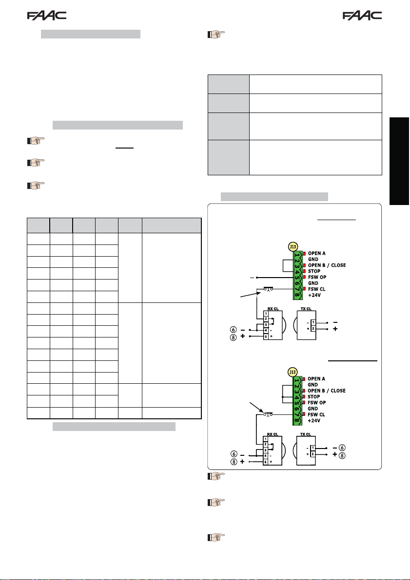
7.3 POSITIONING LIMIT SWITCHES
To ensure correct positioning of the limit switch magnets, the control unit must be installed and
correctly connected with all control and safety accessories.
The operator is equipped with a magnetic limit switch sensor built directly into the electronic control board.
The gate is stopped, during opening or closing, when the polarised magnet secured to the upper part of the rack
activates the sensor.
1. Check that the operator is set for manual operating mode as described in the instructions
for the operator.
2. Move the gate to opening position manually, leaving 40 mm from the limit switch mechanical stop (see Fig. 16).
3. Slide the magnet with the CIRCLE on the rack in the direction of the motor. As soon as
the LED for the FCA limit switch on the board goes off, secure with the appropriate screws.
4. Move the gate to closing position manually, leaving 40 mm from the limit switch mechanical stop.
5. Slide the magnet with the SQUARE on the rack in the direction of the motor. As soon as
the LED for the FCC limit switch on the board goes off, secure with the appropriate screws.
6. Check that the relevant limit switch LED goes off correctly at the end of the opening and
closing movement and make the necessary changes to the position of the limit switch
magnet position if necessary.
To avoid damage to the operator and/or interruptions in the operation of the
automated system, approximately 40 mm must be left from the mechanical
limit switch stops.
For correct operation of the operator, the magnet with
the CIRCLE must be
used as an OPENING limit switch and
the magnet with the
SQUARE must be used
as a CLOSING limit
switch.
(SEE FIG. 16)
When using a system
with MASTER/SLAVE
configuration, the
limit switch magnets
must be installed as
shown in Fig. 17.
ENGLISH
Fig. 16
MASTER/SLAVE
Fig. 17
15
Page 17

7.4 MASTER / SLAVE CONFIGURATIONS
(1)
(2)
BUS
2 EASY
(1)
(2)
BUS
2 EASY
Should you need to build a system with opposing leaves that must be activated simultaneously
for opening and closing the gate, you must connect and configure two E721 devices in Master/Slave mode.
The MASTER equipment (parameter Ct of the first programming level configured as MA ) must have all the necessary
connections for correct operation of the system (photocells, safety switches, radio, opening pulses, flashing light)
while the SLAVE equipment (parameter
terminal board J13, as all the inputs present are completely ignored. The two devices will communicate with each
other through BUS-2EASY using two-pole POLARISED wiring on the J12 terminal board.
The MASTER device will completely control the SLAVE device through BUS-2EASY and will manage all the movements
and time of both leaves.
Avoid any type of connection and wiring to terminal board J13 of the SLAVE unit.
The BUS connection between the two boards must be POLARISED following the sequence of the
poles of the J12 terminal board (POLE (1) - POLE (2)) - (see Fig. 18).
When a unit is configured as a SLAVE, this will force the values of some programming parameters
ENGLISH
no longer displayed in the menu (
again, the previously forced values are stored in the program.
7.4.1 MASTER / SLAVE WIRING
Ct of the first programming level configured as SL), must not be wired with
LO-PA-Pb-Ph-Op
). By placing the board in MASTER mode
Do not connect
anything to this
terminal board
E721 MASTER E721 SLAVE
Fig. 18
7.4.2 MASTER/SLAVE SETUP PROCEDURE
The SETUP request signalled by the flashing S0 on the display can occur both on the MASTER unit
and on the SLAVE unit. In the latter case, the MASTER unit will display an error
SETUP procedure can only be started from the MASTER unit.
To SETUP a MASTER/SLAVE system, follow the steps below:
1. Release both leaves, place them in the middle of travel and lock again (see procedure no.1 Par. 7.5 SETUP)
2. Keep pressed the SETUP button on the MASTER board until the MASTER gate begins to move.
3. At this point the MASTER gate will perform a complete SETUP procedure (see Par. 7.5 SETUP)
4. Once you have correctly completed the SETUP of the MASTER board, the complete SETUP procedure of the SLAVE
board begins (see Par. 7.5 SETUP).
5. Once this procedure has also been completed the MASTER checks the position of the SLAVE leaf and places it in
the same position (open or closed) as the MASTER leaf.
6. Procedure completed.
In case of error or non-completion of the above-mentioned SETUP procedure, you must repeat it
completely starting from point no.1.
16
91. In any case, the
Page 18

7.4 SETUP
When the board is powered when no SETUP
has ever been carried out, or if the board
requires it, the code S0 will flash on the
display together with the SETUP LED to indicate that SETUP must be carried out.
To ensure the effective outcome of the
SETUP procedure, carefully check the correct polarity of the magnetic limit switches
as described in the previous paragraph.
Proceed as follows to carry out the SETUP:
1. Place the gate at half its travel (very important for a
successful SETUP) and check that both the FCA and
FCC LEDs are on. Otherwise, the board will signal
error 12 (see tab. 5)
2. Press and hold the SETUP (SW4) push-button until the
gate begins to move slowly and stops when it reaches
the limit switch. If the limit switch reached is the closing
switch (with the SQUARE) the device stores that point
as the closing stop, conversely if the limit switch is the
opening switch (with the CIRCLE) the device stores
that point as the opening stop. During that stage,
flashes on the display
3. The gate automatically begins to move slowly in the
opposite direction and then stops when it reaches the
limit switch. If the limit switch reached is the opening
switch (with the SQUARE) the device stores that point
as the opening stop, conversely if the limit switch is
the closing switch (with the SQUARE) the device stores
that point as the closing stop. During that stage,
S1
S3 flashes on the display
4. According to the final limit switch reached, the device takes up a status of closed (
In the second case, issue an OPEN pulse to close the
gate.
8 TESTING THE AUTOMATED SYSTEM
After installation and programming, check the system is
operating correctly. Above all, check that the safety devices operate correctly and ensure that the current safety
regulations are met.
Remember that the second programming
level features the encoder configuration
parameter (parameter
encoder located on the board acts as
an anti-crushing device. During the open/
closing phase, should the gate collide
with an obstacle, the “virtual” encoder
will cause the motion to reverse. At the
next motion in the same direction, an
obstacle in the same position will cause
the motor to stop. It is essential to correctly
configure this parameter to adjust the
correct sensitivity of the “virtual” encoder
with respect to obstacles during motion.
00) or open (01).
EC
). This “virtual”
9 ALARM AND ERROR SIGNALS
If alarms occur (conditions that do not impair the operation of the gate) or errors (conditions that lock the gate
operation) the display shows a number relating to the
current condition.
The ALARM or ERROR signals disappear at
the next cycle only if the triggering cause
is removed.
9.1 ALARMS
When an ALARM occurs, the ERROR LED
begins to flash and a number relating to
the current fault appears on the display
when the + and - keys are pressed.
Tab. 4 indicates all the alarms that may be shown on the
display.
Tab. 4 - Alarms
Limited MOTOR current
22
LAMP output short-circuited
24
Obstacle detection (visible for 10 secs)
27
XF radio code memory-module full (visible
30
for 10 secs)
Service request
40
Forced default programming reset
46
9.2 ERRORS
When an ERROR occurs, LED DL20 comes
on with a fixed light and a number relating
to the current fault appears on the display
when the + and - keys are pressed.
Tab. 5 indicates all the errors that may be shown on the
display.
Tab. 5 - Errors
Board faulty
01
Motor faulty
03
Motor lock locked closed (check the motor
06
lock and replace if necessary)
Gate too heavy or too much friction (try to
07
increase motor power)
BUS-2EASY device error (e.g. same address
08
on two photocell pairs; check address)
Both limit switches with the same polarity
10
Limit switch engaged at the beginning of
12
SETUP
Time-out finished
15
No communication with the SLAVE unit -
90
SLAVE unit missing
Error on the SLAVE unit
91
Error on the SLAVE unit
92
Errors 90 91 and 92 are displayed
only on E721 configured as MASTER and
in particular 91and 92 indicate errors
present on the SLAVE unit. Should such
errors be displayed, we recommend you
check on the SLAVE unit the type of error
shown on the display to solve it and restore
correct operation of the system.
ENGLISH
17
Page 19

10 FUNCTION LOGICS
In brackets, the effects on the other inputs when
the pulse is active.
The CLOSE command can be enabled on the OPEN
B input from programming level 2.
LOGIC "E" PULSES
STATUS OF AUTOMATED SYSTEM
CLOSED opens the gate opens the gate partially no effect
DURING OPENING locks operation (1) locks operation recloses the gate locks operation see 2nd level prog. no effect
OPEN recloses the gate (1) recloses the gate recloses the gate
DURING CLOSING reopens the gate reopens the gate no effect locks operation no effect
ENGLISH
LOCKED closes the gate closes the gate closes the gate
LOGIC "EP" PULSES
STATUS OF AUTOMATED SYSTEM
CLOSED opens the gate opens the gate partially n o effect
DURING OPENING locks operation (1) locks operation recloses the gate locks operation see 2nd level prog. no effect
OPEN recloses the gate (1) recloses the gate recloses the gate
DURING CLOSING locks operation locks operation no effect locks operation no effect
LOCKED
LOGIC "A" PULSES
STATUS OF AUTOMATED SYSTEM
CLOSED
DURING OPENING no effect (1) no effect recloses the gate locks operation see 2nd level prog. no effect
OPEN IN PAUSE reloads pause time (1) reloads pause time B recloses the gate locks operation no effect
DURING CLOSING reopens the gate reopens the gate no effect locks operation no effect
LOCKED closes the gate closes the gate closes the gate
LOGIC "A1" PULSES
STATUS OF AUTOMATED SYSTEM
CLOSED
DURING OPENING no effect (1) no effect recloses the gate locks operation see 2nd level prog.
OPEN IN PAUSE reloads pause time (1) reloads pause time B recloses the gate locks operation no effect
DURING CLOSING reopens the gate reopens the gate no effect locks operation no effect
LOCKED closes the gate closes the gate closes the gate
OPEN A OPEN B CLOSE STOP FSW OP FSW CL FSW CL/OP
OPEN A OPEN B CLO SE STOP FSW OP FSW CL FSW CL/OP
resumes motion in reverse
direction. After STOP, always
OPEN A OPEN B CL O SE STOP FSW OP FSW CL FSW CL/OP
opens and recloses after
the pause time
OPEN A OPEN B CLO SE STOP FSW OP FSW CL FSW CL/OP
opens and recloses after
the pause time
closes
resumes motion in reverse
direction. After STOP, always
closes
opens the gate partially
and closes it after pause
time B
opens the gate partially
and closes it after pause
time B
closes the gate
no effect
no effect
If enabled during leaf motion, the SAFE command
will immediately and completely reverse it; when
the automated system is stopped, if kept enabled
it will prevent its movement.
no effect
(OPEN inhibited)
no effect
(OPEN/CLOSE inhibited)
no effect
(OPEN/CLOSE inhibited)
no effect
(OPEN inhibited)
no effect
(OPEN/CLOSE inhibited)
no effect
(OPEN/CLOSE inhibited)
no effect
(OPEN inhibited)
no effect
(OPEN/CLOSE inhibited)
no effect
(OPEN inhibited)
no effect
(OPEN/CLOSE inhibited)
(1) During the partial opening cycle, an OPEN A pulse causes total opening
no effect
(OPEN inhibited)
no effect
no effect
(OPEN inhibited)
no effect
(OPEN inhibited)
no effect
no effect
(OPEN inhibited)
no effect
(OPEN inhibited)
no effect
(OPEN inhibited)
no effect
(OPEN inhibited)
no effect
(OPEN inhibited)
18
no effect
no effect
(CLOSE inhibited)
reverses to opening (see
2nd level prog.)
no effect
(CLOSE inhibited)
no effect
no effect
(CLOSE inhibited)
reverses to opening (see
2nd level prog.)
no effect
(CLOSE inhibited)
no effect
reloads pause time
(CLOSE inhibited)
reverses to opening (see
2nd level prog.)
no effect
(CLOSE inhibited)
no effect
continues to open and
recloses immediately
locks and immediately
closes on disengagement
reverses to opening (see
2nd level prog.)
no effect
(CLOSE inhibited)
no effect
(OPEN inhibited)
locks and opens on
disengagement (OPEN
locks - stores CLOSE)
no effect
(OPEN/CLOSE inhibited)
locks and opens on
disengagement (OPEN
locks - stores CLOSE)
no effect (OPEN locks
- stores CLOSE)
no effect
(OPEN inhibited)
locks and opens on
disengagement (OPEN
locks - stores CLOSE)
no effect
(OPEN/CLOSE inhibited)
locks and opens on
disengagement (OPEN
locks - stores CLOSE)
no effect (OPEN locks
- stores CLOSE)
no effect
(OPEN inhibited)
locks and opens on
disengagement
(stores CLOSE)
reloads pause time
(CLOSE inhibited)
locks and opens on
disengagement
(stores CLOSE)
no effect
(OPEN/CLOSE inhibited)
no effect
(OPEN inhibited)
locks and opens on
disengagement
(stores CLOSE)
reloads pause time
(CLOSE inhibited)
locks and opens on
disengagement
(stores CLOSE)
no effect
(OPEN/CLOSE inhibited)
Page 20

LOGIC "AP" PULSES
STATUS OF AUTOMATED SYSTEM
CLOSED
OPEN A OPEN B CLO SE STOP FSW OP FSW CL FSW CL/OP
opens and recloses after
the pause time
opens the gate partially
and closes it after pause
time B
no effect
no effect
(OPEN inhibited)
no effect
(OPEN inhibited)
no effect
DURING OPENING locks operation (1) locks operation recloses the gate locks operation see 2nd level prog. no effect
OPEN IN PAUSE locks operation (1) locks operation recloses the gate locks operation no effect
DURING CLOSING reopens the gate reopens the gate no effect locks operation no effect
LOCKED closes the gate closes the gate closes the gate
no effect
(OPEN/CLOSE inhibited)
no effect
(OPEN inhibited)
reloads pause time
(CLOSE inhibited)
reverses to opening (see
2nd level prog.)
no effect
(CLOSE inhibited)
LOGIC "At" (2) PULSES
STATUS OF AUTOMATED SYSTEM
CLOSED
OPEN A OPEN B CLO SE STOP FSW OP FSW CL FSW CL/OP
opens and recloses after
the pause time
opens the gate partially
and closes it after pause
time B
no effect
no effect
(OPEN inhibited)
no effect
(OPEN inhibited)
no effect
DURING OPENING no effect (1) no effect recloses the gate locks operation reverses to closing (1) no effect
OPEN IN PAUSE reloads pause time (1) reloads pause time recloses the gate locks operation no effect
DURING CLOSING reopens the gate reopens the gate no effect locks operation no effect
LOCKED closes the gate closes the gate closes the gate
no effect
(OPEN/CLOSE inhibited)
no effect
(OPEN inhibited)
reloads pause time
(CLOSE inhibited)
reverses to opening (see
2nd level prog.)
no effect
(CLOSE inhibited)
LOGIC "S" PULSES
STATUS OF AUTOMATED SYSTEM
CLOSED
DURING OPENING reverses to closing (1) reverses to closing (1) recloses the gate locks operation see 2nd level prog.
OPEN IN PAUSE recloses the gate (1) recloses the gate recloses the gate locks operation no effect
DURING CLOSING reopens the gate reopens the gate no effect locks operation no effect
LOCKED closes the gate closes the gate closes the gate
OPEN A OPEN B CLO SE STOP FSW OP FSW CL FSW CL/OP
opens and recloses after
the pause time
opens the gate partially
and closes it after pause
time B
no effect
no effect
(OPEN inhibited)
no effect
(OPEN/CLOSE inhibited)
no effect
(OPEN inhibited)
no effect
(OPEN inhibited)
no effect
continues to open and
recloses immediately
locks and immediately
closes on disengagement
reverses to opening (see
2nd level programming)
and closes immediately at
no effect
(CLOSE inhibited)
the end
no effect
(OPEN inhibited)
locks and opens on
disengagement (OPEN
locks - stores CLOSE)
reloads pause time
(CLOSE inhibited)
locks and opens on
disengagement (OPEN
locks - stores CLOSE)
no effect
(OPEN/CLOSE inhibited)
no effect
(OPEN inhibited)
locks and opens on
disengagement
(stores CLOSE)
reloads pause time
(CLOSE inhibited)
locks and opens on
disengagement
(stores CLOSE)
no effect
(OPEN/CLOSE inhibited)
no effect
(OPEN inhibited)
locks and opens
on disengagement (stores
CLOSE)
locks and closes on
disengagement
locks and on disengage-
ment opens and at the
end immediately closes
no effect
(OPEN/CLOSE inhibited)
ENGLISH
LOGIC "SP" PULSES
STATUS OF AUTOMATED SYSTEM
CLOSED
OPEN A OPEN B CLO SE STOP FSW OP FSW CL FSW CL/OP
opens and recloses after
the pause time
opens the gate partially
and closes it after pause
time B
no effect
no effect
(OPEN inhibited)
no effect
(OPEN inhibited)
DURING OPENING locks operation (1) locks operation recloses the gate locks operation see 2nd level prog.
OPEN IN PAUSE recloses the gate (1) recloses the gate recloses the gate locks operation no effect
DURING CLOSING locks operation locks operation n o effect locks operation no effect
LOCKED
resumes motion in reverse
direction. After STOP, always
closes
resumes motion in reverse
direction. After STOP, always
closes
recloses the gate
no effect
(OPEN/CLOSE inhibited)
(1) During the partial opening cycle, an OPEN A pulse causes total opening
no effect
(OPEN inhibited)
19
no effect
continues to open and
recloses immediately
locks and immediately
closes on disengagement
reverses to opening (see
2nd level prog.)
no effect
(CLOSE inhibited)
no effect
(OPEN inhibited)
locks and on disengagement
opens and at the end immediately
closes (OPEN locks - stores CLOSE)
locks and immediately
closes on disengagement
locks and opens on
disengagement
(stores CLOSE)
no effect
(OPEN/CLOSE inhibited)
Page 21

LOGIC "SA" PULSES
STATUS OF AUTOMATED SYSTEM
CLOSED
OPEN A OPEN B CLO SE STOP FSW OP FSW CL FSW CL/OP
opens and recloses after
the pause time
Opens the gate partially
and closes it after pause
time B
no effect
no effect
(OPEN inhibited)
no effect
(OPEN inhibited)
DURING OPENING no effect (1) no effect recloses the gate locks operation see 2nd level prog. no effect
OPEN IN PAUSE recloses the gate (1) recloses the gate recloses the gate locks operation no effect
DURING CLOSING reopens the gate reopens the gate no effect locks operation no effect
LOCKED closes the gate closes the gate closes the gate
no effect
(OPEN/CLOSE inhibited)
no effect
(OPEN inhibited)
LOGIC "B" PULSES
STATUS OF AUTOMATED SYSTEM
ENGLISH
CLOSED opens the gate / no effect
OPEN A / C LO S E STOP FSW OP FSW CL FSW CL/OP
no effect
(OPEN inhibited)
no effect
(OPEN inhibited)
DURING OPENING no effect / closes the gate locks operation see 2nd level prog. no effect
OPEN no effect / closes the gate
no effect
(OPEN/CLOSE inhibited)
no effect
DURING CLOSING opens the gate / no effect locks operation no effect
LOCKED opens the gate / closes the gate
LOGIC bC
STATUS OF AUTOMATED SYSTEM
PULSES DURING OPENING/COMMANDS MAINTAINED
DURING CLOSING
OPEN A / C LO S E STOP FSW OP FSW CL FSW CL/OP
CLOSED opens the gate / no effect
no effect
(OPEN/CLOSE inhibited)
no effect
(OPEN inhibited)
no effect
(OPEN inhibited)
PULSES
no effect
(OPEN inhibited)
DURING OPENING no effect / closes the gate locks operation see 2nd level prog. no effect
OPEN no effect / closes the gate
no effect
(OPEN/CLOSE inhibited)
no effect
DURING CLOSING opens the gate / no effect locks operation no effect
LOCKED opens the gate / closes the gate
no effect
(OPEN/CLOSE inhibited)
no effect
(OPEN inhibited)
LOGIC "C" COMMANDS MAINTAINED PULSES
STATUS OF AUTOMATED SYSTEM
CLOSED opens the gate / no effect
OPEN A / C LO S E STOP FSW OP FSW CL FSW CL/OP
no effect
(OPEN inhibited)
no effect
(OPEN inhibited)
DURING OPENING no effect / closes the gate locks operation see 2nd level prog. no effect
OPEN no effect / closes the gate
no effect
(OPEN/CLOSE inhibited)
no effect
no effect
reloads pause time
(CLOSE inhibited)
reverses to opening (see
2nd level prog.)
no effect
(CLOSE inhibited)
no effect
no effect
(CLOSE inhibited)
reverses to opening (see
2nd level prog.)
no effect
(CLOSE inhibited)
no effect
no effect
(CLOSE inhibited)
reverses to opening (see
2nd level prog.)
no effect
(CLOSE inhibited)
no effect
no effect
(CLOSE inhibited)
no effect
(OPEN inhibited)
locks and opens on
disengagement
(stores CLOSE)
reloads pause time
(CLOSE inhibited)
locks and opens on
disengagement
(stores CLOSE)
no effect
(OPEN/CLOSE inhibited)
no effect
(OPEN inhibited)
locks and opens on
disengagement (stores
OPEN/CLOSE)
no effect
(OPEN/CLOSE inhibited)
locks and opens on
disengagement (stores
OPEN/CLOSE)
no effect
(OPEN/CLOSE inhibited)
no effect
(OPEN inhibited)
locks and opens on
disengagement (stores
OPEN/CLOSE)
no effect
(OPEN/CLOSE inhibited)
locks and opens on
disengagement (stores
OPEN/CLOSE)
no effect
(OPEN/CLOSE inhibited)
no effect
(OPEN inhibited)
locks and on disengage-
ment 2nd level prog.
no effect
(OPEN/CLOSE inhibited)
DURING CLOSING opens the gate / no effect locks operation no effect locks operation locks operation
LOCKED opens the gate / closes the gate
(2) When turned on, the board checks the inputs and if an OPEN A or B command is active, it opens the leaf or gate. Otherwise it closes it.
no effect
(OPEN/CLOSE inhibited)
(1) During the partial opening cycle, an OPEN A pulse causes total opening
no effect
(OPEN inhibited)
no effect
(CLOSE inhibited)
no effect
(OPEN/CLOSE inhibited)
20
Page 22

Le descrizioni e le illustrazioni del presente manuale non sono impegnative. La FAAC si riserva il diritto, lasciando inalterate le caratteristiche essenziali dell’apparecchiatura, di apportare in qualunque momento e senza impegnarsi
ad aggiornare la presente pubblicazione, le modifiche che essa ritiene convenienti per miglioramenti tecnici o per
qualsiasi altra esigenza di carattere costruttivo o commerciale.
The descriptions and illustrations contained in the present manual are not binding. FAAC reserves the right, whilst
leaving the main features of the equipments unaltered, to undertake any modifications it holds necessary for either
technical or commercial reasons, at any time and without revising the present publication.
Les descriptions et les illustrations du présent manuel sont fournies à titre indicatif. FAAC se réserve le droit d’apporter à
tout moment les modifications qu’elle jugera utiles sur ce produit tout en conservant les caractéristiques essentielles,
sans devoir pour autant mettre à jour cette publication.
Die Beschreibungen und Abbildungen in vorliegendem Handbuch sind unverbindlich. FAAC behält sich das Recht
vor, ohne die wesentlichen Eigenschaften dieses Gerätes zu verändern und ohne Verbindlichkeiten in Bezug auf die
Neufassung der vorliegenden Anleitungen, technisch bzw. konstruktiv/kommerziell bedingte Verbesserungen vorzunehmen.
Las descripciones y las ilustraciones de este manual no comportan compromiso alguno. FAAC se reserva el derecho,
dejando inmutadas las características esenciales de los aparatos, de aportar, en cualquier momento y sin comprometerse a poner al día la presente publicación, todas las modificaciones que considere oportunas para el perfeccionamiento técnico o para cualquier otro tipo de exigencia de carácter constructivo o comercial.
De beschrijvingen in deze handleiding zijn niet bindend. FAAC behoudt zich het recht voor op elk willekeurig moment de
veranderingen aan te brengen die het bedrijf nuttig acht met het oog op technische verbeteringen of alle mogelijke
andere productie- of commerciële eisen, waarbij de fundamentele eigenschappen van de apparaat gehandhaafd
blijven, zonder zich daardoor te verplichten deze publicatie bij te werken.
FAAC S.p.A.
Via Calari, 10
40069 Zola Predosa (BO) - ITALIA
Tel. 0039.051.61724 - Fax. 0039.051.758518
www.faacgroup.com
532014 - Rev. B
 Loading...