

Page 1
1 BOX LAYOUT ..................................................................................................................2
2 WARNINGS ....................................................................................................................3
3 LAYOUT AND CONNECTIONS .........................................................................................3
4 TECHNICAL SPECIFICATIONS ........................................................................................4
4.1 DESCRIPTION OF COMPONENTS ...........................................................................................4
4.2 DESCRIPTION OF TERMINAL-BOARDS ....................................................................................4
5 PROGRAMMING THE LOGIC ..........................................................................................4
6 PROGRAMMING THE SPEED ........................................................................................... 4
7. START-UP ........................................................................................................................5
7.1 LEDS CHECK ........................................................................................................................5
DIPS-SWITCH PROGRAMMING
7.2
7.3 PRE-FLASHING ....................................................................................................................5
7.4 TIME LEARNING - SET-UP.......................................................................................................5
7.4.1 AUTOMATIC SET-UP ........................................................................................................................5
7.4.2 MANUAL SET-UP .............................................................................................................................5
8 INSTALLATION OF BUS ACCESSORIES .............................................................................6
8.1 ADDRESSING BUS ENCODER ................................................................................................6
8.2 ADDRESSING THE BUS PHOTOCELLS ....................................................................................6
8.3 MEMORY STORAGE OF BUS ACCESSORIES..........................................................................7
9 MEMORY STORING THE RADIO CODE ............................................................................ 7
9.1 MEMORY STORAGE OF DS RADIO CONTROLS ......................................................................8
9.2 MEMORY STORAGE OF SLH RADIO CONTROLS ....................................................................8
9.3 MEMORY STORAGE OF LC RADIO CONTROLS (for some markets only) .............................8
9.3.1 REMOTE MEMORY STORAGE OF LC RADIO CONTROLS .................................................................9
9.4 RADIO CONTROLS DELETION PROCEDURE ...........................................................................9
10 CONNECTION OF BUFFER BATTERIES (OPTIONAL) ........................................................... 9
10.1 BATTERY KIT .......................................................................................................................... 9
11 AUTOMATED SYSTEM TEST..............................................................................................9
12 LOGIC TABLES ...............................................................................................................10
INDEX
..............................................................................................5
CE DECLARATION OF CONFORMITY
Manufacturer: FAAC S.p.A.
Address: Via Benini, 1 - 40069 Zola Predosa BOLOGNA - ITALY
Declares that: Control board mod. E 700,
• conforms to the essential safety requirements of the following EEC directives:
73/23/EEC and subsequent amendment 93/68/EEC.
89/336/EEC and subsequent amendment 92/31/EEC and 93/68/EEC
Additional information:
This product underwent a test in a typical, uniform configuration
(all products made by FAAC S.p.A)
Bologna, 01 January 2007. The Managing Director
A. Bassi
ENGLISH
• Important! For the safety of people, it is important that all the instructions be carefully observed.
WARNINGS
• Incorrect installation or incorrect use of the product could cause serious harm to people.
• Carefully read the instructions before beginning to install the product and keep them for future
reference.
• The symbol
of the automated system.
• The symbol
product.
indicates notes that are important for the safety of persons and for the good condition
draws your attention to the notes on the characteristics and operation of the
1
Page 2
ELECTRICAL BOX E700
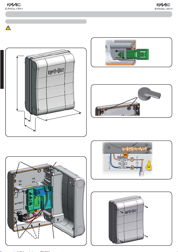
1 BOX LAYOUT
The box contains the E700 electronic unit and the devices
to power it. It must therefore be handled with care during all
installation stages, to avoid damaging its components.
The dimensions of the box are shown in Fig.1:
ENGLISH
306
The lid hinges can be moved upward to allow opening the box
housing (Fig. 3); they can also be removed and re-positioned
in order to enable the lid to open to the right or left.
Fig. 3
When you have secured the box in the selected position, cover
the securing holes (ref. Fig.2) and the screws with the supplied
plugs as shown in Fig.4.
64
130
225
Dimensions in mm
Fig. 1
Fig. 2 shows the four 5 mm diam. holes for securing the
box (ref.) to the wall, the three fittings M16/M20/M25 for
installing the cable grippers (ref.) and the two lid hinges
(ref.).
Fig. 2
Fig. 4
After you have finished the operations to connect the control
board with the various parts of the automated system, close
the box, positioning the lid in its seat with seal.
Connect the supply as shown in Fig. 5.
Fig. 5
Next, tighten the four supplied screws to guarantee the degree
of protection against external agents (Fig.6).
Fig. 6
2
Page 3
2 WARNINGS
Before attempting any work on the control unit (connections, maintenance), always turn off power.
- Install, upstream of the system, a differential thermal breaker with adequate tripping threshold,
- Always separate power cables from control and safety cables (push-button, receiver, photocells, etc.).
- To avoid any electrical disturbance, use separate sheaths or a screened cable (with the screen earthed).
3 LAYOUT AND CONNECTIONS
(PARTIAL OPENING)
(TOTAL OPENING)
230 Vac 50Hz
or
115 Vac 60Hz *
1
ENGLISH
1
*
The power supply is related to the E700 purchased version.
Fig. 7
3
Page 4
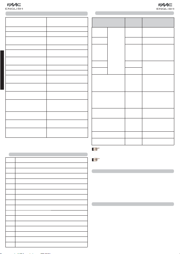
4 TECHNICAL SPECIFICATIONS
3
STOP
Device with NC
contact which causes
the automated
system to shut down
230Vac (+6% -10%) - 50Hz
Power supply voltage
Absorbed power
Motor max. load
Accessories max. current
(+24V)
BUS Accessories max.current
Operating ambient
temperature
2
Fuses
*
Function logics
Work time (time-out)
ENGLISH
Pause time
Terminal board inputs
Connector inputs
Terminal board outputs
Programmable functions
Learning functions
Integrated radio channels
type
2
*
The power supply and the fuse are related to the purchased
version.
2
*
or
115Vac (+6% -10%) - 60Hz
20W
150W x 2
100 mA
400 mA
-20°C - +55°C
F1 = self-resetting;
F2 = T2A-250V or T4A-120V
EP, A
3 minute (fixed)
Varies according to learning
(max. 10 min.)
Open A, Open B, Stop, BUS
(I/O)
Power supply, battery
module XF 433 or XF 868
Motors, flashing lamp, power
supply to accessories,
electric lock, service light
contact (90 sec fixed)
Logic (A, EP), Speed (high
4.8°/sec and low 3.7°/sec)
Pause time, leaf 2 delay at
closing
DS, SLH (max 250 channels)
LC (max 250 channels - FOR
SOME MARKETS ONLY)
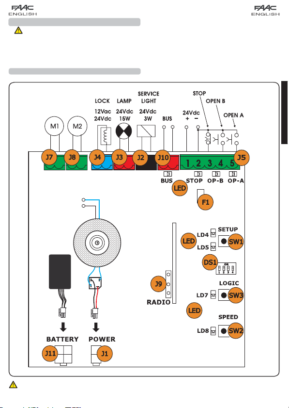
4.1 DESCRIPTION OF COMPONENTS
J1 POWER SUPPLY connector
J2
SERVICE LIGHT command terminal-board
J3 FLASHING LAMP terminal-board
J4 ELECTRIC LOCK terminal-board
J5 COMMANDS terminal-board
J7 MOTOR 1 terminal-board
J8 MOTOR 2 terminal-board
J9 Rapid connection for XF MODULE
J10 BUS terminal-board
J11 BATTERY connector
SW1 SET-UP push-button
SW2 SPEED push-button
SW3 LOGIC push-button
DS1 Programming Dip-switch
F1 Accessories protective fuse
F2 Fuses protecting transformers and motors
LED Signalling LEDs
4.2 DESCRIPTION OF TERMINAL-BOARDS
Terminal and/or
terminal-board
1
Description Device connected
Power supply for
+24V
accessories
2 GND Negative
Device with NC
STOP
BUS
SERVICE
LIGHT
LAMP
LOCK
contact which causes
the automated
system to shut down
Device with N.O
contact (see chap.
FUNCTION LOGICS)
Safety and control
devices with BUS
technology
Service Light control
output (connect a
relay coil at 24Vdc100mA max)
Flashing lamp 24Vdc
- 15W
Electric lock 12Vac or
24 Vdc (to be installed
on leaf 1)
J5
3
4 OPEN B
5 OPEN A
J10
RED terminal
J2
GREY terminal
J3
ORANGE terminal
J4
BLUE terminal
J7 MOT1 Motor 1 (leaf 1)
J8 MOT2 Motor 2 (leaf 2)
Leaf 1 means the leaf which opens first during
the opening operation.
The service light control is active during the
entire gate opening or closing movement and
for the successive 90 seconds.
5 PROGRAMMING THE LOGIC
The function logic can be selected at any time by pressing
push-button SW3.
The selected logic is then displayed on LED LD7:
LED on = AUTOMATIC logic (A)
LED off = SEMIAUTOMATIC STEPPED logic (EP)
6 PROGRAMMING THE SPEED
The operating speed can be adjusted at any time by pressing
push-button SW2.
The selected logic is then displayed on LED LD8:
LED on = HIGH speed (4.8 °/sec)
LED off = LOW speed (3.7 °/sec)
4
Page 5

7. START-UP
7.1 LEDS CHECK
The following table shows the status of the LEDs in relation to
the status of the inputs (the closed at rest automated system
condition is shown in bold).
Check the status of the signalling LEDs as per table below:
Before any moviment is executed, the Encoders
Tab.1 – Operation of inputs status LEDs
LED ON (closed contact) OFF (open contact)
STOP Command disabled Command enabled
OPEN A Command enabled Command disabled
OPEN B Command enabled Command disabled
BUS
7.2 DIPS-SWITCH PROGRAMMING
The following tables show the settings of the DS1 dip-switches
for programming encoder sensitivity, reverse thrust, and operator force.
See par. 8.3
Tab. 2 - DS1 programming (the default settings are shown in bold)
DS1 DS2 DS3 DS4 Description
ON ON HIGH FORCE
ON OFF MEDIUM - HIGH FORCE
OFF ON MEDIUM - LOW FORCE
OFF OFF LOW FORCE
7.3 PRE-FLASHING
The pre-flashing function can be activated and disabled
(following an OPEN command, the unit activates the flashing
lamp for 3 seconds before it starts the movement). Procedure:
1.
2.
ON HIGH ENCODER SENSITIVITY
OFF LOW ENCODER SENSITIVITY
ON REVERSE THRUST ON
OFF REVERSE THRUST OFF
If you connect an electric lock to terminal J4,
position DS4 to ON to enable the reversing stroke
(before opening, the motors thrust to close, thus
facilitating the electric lock to uncouple).
If you set dip-switch DS3 to OFF, a special function
is enabled, allowing the gate to operate also
in the event of wind gusts.
Press LOGIC key (SW3) for at least 5 secs. to ACTIVATE
pre-flashing.
Press SPEED key (SW2) for at least 5 secs. to DESACTIVATE
pre-flashing.
In both cases check if the LED of the pressed key
changes its status: in such cases it means that
the function of the key and not the pre-flashing
was changed.
When the board is powered up and a SET-UP cycle has never
been executed, LEDs LD4 and LD5 begin to flash slowly to signal
that a SET-UP cycle must be executed.
There are two possible types of SETUP: AUTOMATIC and
MANUAL
To execute an AUTOMATIC SET-UP, follow the procedure below:
1.
2.
3.
4.
5.
6.
7.
8.
9.
To execute a MANUAL SET-UP, follow the procedure below:
1.
2.
3.
4.
5.
6.
7.
8.
9.
5
7.4 TIME LEARNING - SET-UP
must be wired as explained on chapter 8.1
page 6.
Before any manoeuvre is executed, a SETUP
cycle must first be run.
During SETUP do not interrupt the photocells
because their interruption causes the immediate
stop of the leaves. To end the procedure,
repeat SETUP from the beginning.
7.4.1 AUTOMATIC SET-UP
Take the leaves to mid-opening (very important).
Hold down the SET-UP (SW1) push-button until the 2 adjacent
LEDs (LD4 and LD5) light up on steady beam.
Release the SETUP push-button, LEDs LD4 and LD5 begin
to flash rapidly.
Leaf 2 (if present) starts the closing movement, stopping
when it reaches the closing mechanical stop.
Leaf 1 starts the closing movement, stopping when it
reaches the closing mechanical stop.
Leaf 2 (if present) starts the opening movement after the
Leaf 1 stops opening.
Leaf 2 (if present) stops when it reaches the opening
mechanical stop.
Wait for LEDs LD4 and LD5 to go OFF, which means that the
SETUP procedure has finished.
Give an OPEN pulse to close the gate.
When the SET-UP procedure has been started,
if the leaves at point 4 and 5 open instead of
closing, the motor power supply cables must
be changed over.
When using the AUTOMATIC SET-UP, the slow
down spaces, the leaf opening and closing
delays, and the pause time (30 sec., with A
logic), are all preset by the board and cannot
be modified.
7.4.2 MANUAL SET-UP
Take the leaves to mid-opening (very important).
Hold down the SET-UP (SW1) push-button until the leaf starts
moving.
Release the SET-UP push-button, LEDs LD4 and LD5 begin
to flash rapidly
Leaf 2 (if present) starts the closing movement, stopping
when it reaches the closing mechanical stop
Leaf 1 starts the closing movement, stopping when it
reaches the closing mechanical stop
Leaf 1 starts the closing movement, stopping when it
reaches the closing mechanical stop.
Leaf 2 (if present) starts the opening movement the after
Leaf 1 stops opening.
Leaf 2 (if present) stops when it reaches the opening
mechanical stop.
If LOW force was set, wait for about 5 sec checking if the
flashing lamp goes OFF.
ENGLISH
Page 6
10.
If the A Logic was selected, the board begins to count
the pause time (max 10 min) and, after the required time
has elapsed, give an OPENING pulse to continue the
procedure. Otherwise, if you have selected the EP logic,
give an OPEN pulse to continue the procedure.
11.
Leaf 2 (if present) starts the closing movement an the board
begins to count the delay of the leaf 1 at closing.
12.
After the required time has elapsed, give an OPEN pulse
to make leaf 1 start the closing movement. If leaf 2 is not
present, the pulse given in point 9 directly makes leaf 1
close.
13.
Leaves 1 and 2 (if present) stop when they reach the closing
mechanical stop.
14.
Wait for LEDs LD4 and LD5 to go OFF, which means that the
SETUP procedure has finished.
When the SET-UP procedure has been started,
if the leaves at point 4 and 5 open instead of
closing, the motor power supply cables must
ENGLISH
be changed over.
When using the MANUAL SET-UP, the slow-down
spaces, and leaf delays at opening are preset
by the board and cannot be modified. However,
delay at leaf closing and pause time can be
programmed during learning.
8 INSTALLATION OF BUS ACCESSORIES
This board is supplied with a BUS circuit enabling easy
connection of a high number of BUS accessories (e.g. up to
16 photocells pairs), using only two cables.
Below we describe the addressing and memory storage of the
encoders and BUS photocells.
For other future accessories, refer to the specific instructions.
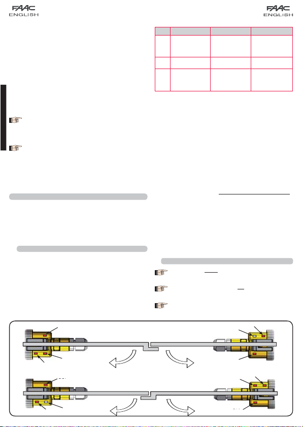
8.1 ADDRESSING BUS ENCODER
Connection of the BUS input to the control board is via the
bipolar cables which come out of the encoders.
Unlike the case of the photocell devices, the polarity of the BUS
line connection determines whether the encoder belongs to
one leaf rather then the other.
This is why you must pay great attention to the indications of
the status LEDs on the body of each encoder (Fig.8).
Below we list the functions of LEDs LD1, DL2, and DL3, and their
statuses:
DL1
Tab. 3 - Encoder connection and LED status
LED LIGHTED FLASHING OFF
Power ON
and BUS
DL 1
communicating
with board
DL 2 Leaf 1 encoder / Leaf 2 encoder
Leaf
DL 3
not moving
DL 1 must always be lighted to guarantee correct connection
•
between encoder and board.
DL 2 determines the leaf on which the encoder is installed.
•
Providing the configuration is correct, the automated system
will show: an encoder with DL 2 lighted in the leaf 1, and an
encoder with DL 2 OFF in the leaf 2. If there is an incorrect
connection, i.e. indicating two encoders with the same
status of the DL 2 LEDs, during the learning procedure of the
BUS accessories, the DL 1 LEDs of both encoders show the
FLASHING status. In this situation, refer to the configuration
in TAB.3 to define which encoder connection to rotate.
DL 3 indicates, on a steady flashing beam, the reading
•
of the pulses while the leaf is moving. When the leaf is
motionless, DL 3 can be either lighted or OFF.
N.B. in particular motionless leaf positions, DL3 may flutter
considerably. This signal must not be considered a fault.
Power ON
but BUS not
communicating
Pulses read
while leaf
moving
8.2 ADDRESSING THE BUS PHOTOCELLS
Important: the same address must be given to
both transmitter and receiver.
Make sure that there are no two or more
photocells pairs with the same address.
If no BUS accessory is used, leave the BUS
connector free (J10 - Fig. 7).
Fig. 8
OFF
DL2
DL3
No Power or BUS
communication
Leaf not moving
DL3
DL3
DL1
DL2
DL2
LEAF 1 LEAF 2
ON
LEAF 2 LEAF 1
OFF
6
DL1
DL3
DL2
ON
DL1
Page 7

Fig. 9
A maximum of 16 BUS photocell pairs can be connected to
the board.
The photocells are split into groups:
Opening photocells: max 6
Closing photocells: max 7
Opening /Closing photocells: max 2
Photocell used as an OPEN pulse: max 1
Fig. 9 shows a 2-swing leaf automated system indicating the
coverage beams of the photocells:
A: Photocells with OPENING and CLOSING action
B: Photocells with OPENING action
C: Photocells with OPENING action
D: Photocells with CLOSING action
Table 4 shows the programming operations of the dip-switch
inside the transmitter and of the BUS Photocells receiver.
Tab. 4 - Addressing of BUS Photocells
Dip1 Dip2 Dip3 Dip4 Ref. Type
OFF OFF OFF OFF
OFF OFF OFF ON
OFF OFF ON OFF
OFF OFF ON ON
OFF ON ON OFF
OFF ON ON ON
ON OFF OFF OFF
ON OFF OFF ON
ON OFF ON OFF
ON OFF ON ON
ON ON OFF OFF
ON ON OFF ON
ON ON ON OFF
OFF ON OFF OFF
OFF ON OFF ON
ON ON ON ON / OPEN PULSE
B -C OPENING
D CLOSING
OPENING and
A
CLOSING
8.3 MEMORY STORAGE OF BUS ACCESSORIES
You can add the BUS photocells to the system at any time,
simply by memory-storing them on the board, observing the
following procedure:
1.
Install and program the accessories using the required
address (see paragraph
2.
Cut power to the board.
3.
Connect the two accessories cables to the red
terminal-board J10 (any polarity will do).
4.
Power up the board, taking care to first connect the
main power supply (transformer output) and then any
batteries.
5.
Quickly press once only the SW1 (SET-UP) push-button, to
execute learning. The BUS LED flashes.
6.
Give an OPEN impulse, leaves will move and the BUS
learning procedure is over.
The board has memory stored the BUS accessories. Follow the
instructions in the table below to check if the BUS connection
is correct.
8.2)
Tab. 5 - Description of BUS LED
Steady light
Slow flashing
lamp
every 0.5 sec)
Light OFF
(flash every 2.5
sec)
Fast flashing
lamp
every 0.2 sec)
Normal operation (LED ON even in the
absence of photocells)
At least one input engaged: photocell
engaged or not aligned, Open A or Open
(flash
B or Stop input engaged
BUS line short circuited
If you have detected a BUS connection
error, repeat the acquisition procedure. If
the error is repeated, make sure that there
(flash
is not more than one accessory with the
same address in the system (also see the
accessories instructions)
9 MEMORY STORING THE RADIO CODE
The control board has an integrated 2-channel decoding
system (DS, SLH, LC) named OMNIDEC. This system makes it
possible to memory-store both total opening (OPEN A) and
partial opening (OPEN B) of the automated system - this is
made possible by an additional receiver module (Fig.10 ref.
) and radio controls on the same frequency.
The 3 types of radio codes (DS, LSH, LC) cannot
coexist.
Only one radio code can be used at a time.
To change over from one code to another, you
must delete the existing one (see paragraph
on deletion), and repeat the memory-storage
procedure.
7
ENGLISH
Page 8

ENGLISH
9.1 MEMORY STORAGE OF DS RADIO CONTROLS
A maximum of two codes can be stored. One
on the OPEN A channel and one on the OPEN B
channel
1.
On the DS radio control, select the required ON-OFF
combination for the 12 dip-switches.
2.
Press the LOGIC (SW3) or SPEED (SW2) push-button, to
memory store respectively total opening (OPEN A) or partial
opening (OPEN B), and as you hold it down, also press the
SETUP (SW1) push-button. The relevant LED starts to flash
slowly for 5 sec.
3.
Release both push-buttons.
4.
Within these 5 sec., press the appropriate push-button on
the radio control.
5.
The relevant LED lights up on steady beam for 1 second and
then goes OFF, indicating that storage was executed.
6.
To add other radio controls, set the same ON - OFF
combination used in point 1.
9.2 MEMORY STORAGE OF SLH RADIO CONTROLS
A maximum of 250 codes can be memory
stored, split between OPEN A and OPEN B.
1.
On the SLH radio control, simultaneously press and hold
down push-buttons P1 and P2.
2.
The radio control LED begins to flash.
3.
Release both push-buttons.
4.
Press the LOGIC (SW3) or SPEED (SW2) push-button, to
memory store respectively total opening (OPEN A) or partial
opening (OPEN B), and as you hold it down, also press the
SET-UP (SW1) push-button. The relevant LED starts to flash
slowly for 5 sec.
5.
Release both push-buttons.
6.
Within these 5 sec., while the radio control LED is still flashing,
press and hold down the required push-button on the radio
control (the radio control LED lights up on steady beam).
7.
The LED on the board lights up on steady beam for 1
second and then goes OFF, indicating that storage was
executed.
8.
Release the radio control push-button.
9.
Quickly press twice the memory stored radio control
push-button.
Fig. 10
The automated system performs one opening
operation. Make sure that the automated
system is free of any obstacle created by
persons or things.
To add other radio controls, transfer the code of the
memory-stored push-button of the radio control to the relevant
push-button of the radio controls to be added, observing the
following procedure.
•
On the memory stored radio control, simultaneously press
and hold down push-buttons P1 and P2.
•
The radio control LED begins to flash.
•
Release both push-buttons.
•
Press the memory stored push-button and hold it down
(the radio control LED lights up on steady beam).
•
Bring the radio controls near, press and hold down the
push-button of the radio control to be added, releasing
it only after the double flash of the radio control LED,
which indicates memory storage executed.
•
Quickly press twice the push-button of the memory stored
radio control.
The automated system performs one opening
operation. Make sure that the automated
system is free of any obstacle created by
persons or things.
9.3 MEMORY STORAGE OF LC RADIO CONTROLS
(for some markets only)
A maximum of 250 codes can be memory
stored, split between OPEN A and OPEN B.
Use LC remote controls only with receiver module at 433
1.
MHz.
Press the LOGIC (SW3) or SPEED (SW2) push-button, to
2.
memory store respectively total opening (OPEN A) or partial
opening (OPEN B), and as you hold it down, also press the
SETUP (SW1) push-button. The relevant LED starts to flash
slowly for 5 sec.
Release both push-buttons. Within these 5 sec., press the
3.
appropriate push-button on the LC remote control.
The LED lights up on steady beam for 1 second, indicating
4.
memory storage executed, and then resumes flashing for
another 5 sec., during which another radio control (point
4) can be memory stored.
When the 5 sec. have elapsed, the LED goes OFF indicating
5.
the end of the procedure.
To add other radio controls, repeat the operation at point 1.
6.
8
Page 9
+
9.3.1 REMOTE MEMORY STORAGE OF LC RADIO
CONTROLS
Other radio controls can be remotely stored only with the
LC radio controls, i.e. without using the LOGIC-SPEED-SETUP
push-buttons, but using a previously stored radio control.
1.
Get a radio control already stored on one of the 2 channels
(OPEN A or OPEN B ).
2.
Press and hold down push-buttons P1 and P2 simultaneously
until both the LEDs flash slowly for 5 sec.
3.
Within 5 sec. press the push-button of the radio control
that had been memory stored to enable learning on the
selected channel.
4.
The LED on the board relating to the channel being learned
flashes for 5 sec., within which time the code of another
radio control must be transmitted.
5.
The LED lights up on steady beam for 2 seconds, indicating
memory storage executed, and then resumes flashing for
5 sec., during which other radio controls can be memory
stored, and then goes OFF.
9.4 RADIO CONTROLS DELETION PROCEDURE
To delete ALL the input radio control codes, press
push-button LOGIC (SW3) or SPEED (SW2) and, while holding it
down, also press push-button SETUP (SW1) for 10 sec.
The LED relating to the pressed push-button flashes for
1.
the first 5 sec, and then flashes more quickly for the next
5 sec.
Both LEDs light up on steady beam for 2 sec and then go
2.
OFF (deletion completed).
Release both push-buttons.
3.
This operation is NOT reversible. All codes of
radio controls stored as OPEN A and OPEN B will
be deleted.
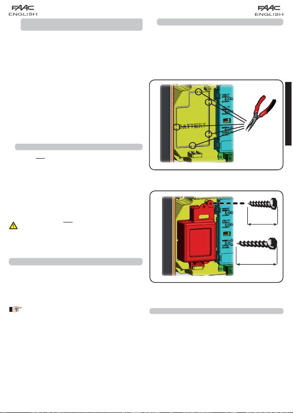
10.1 BATTERY KIT
The buffer battery kit was built for insertion inside the control
board support.
This support (Fig.11 ref.) was pre-moulded to permit the
battery housing to be opened.
Remove the board support material covering the
1.
battery housing, cutting the material connections along
the perimeter.
Fig. 11
Insert the battery in the housing you have just created, and
2.
secure it on the anchoring supports (Fig.12).
10 mm
ENGLISH
10 CONNECTION OF BUFFER BATTERIES (OPTIONAL)
The buffer battery kits will activate the automated system also
in the event of a power cut. The housing of the batteries is
specified in different configurations according to the type of
batteries used.
For correct positioning, observe the following instructions,
referring to your type of battery.
The batteries come into operation when a mains
power cut occurs.
16 mm
+
Fig. 12
To correctly fasten and connect the kit to the control
3.
unit, consult the instructions enclosed with the
battery kit.
11 AUTOMATED SYSTEM TEST
When you have finished programming, check if the system is
operating correctly. In particular, check if the safety devices
are operating correctly.
9
Page 10

12 LOGIC TABLES
ENGLISH
FSW-OPEN
opens leaves and
closes after pause
no effect (opening
no effect
no effect (opening
no effect (opening
opens leaf 1 and
closes after pause
OPEN A OPEN B STOP FSW-OP FSW-CL FSW-OP/CL
opens leaves and
closes after pause
time
no effect (1)
inhibited)
to open at
stops and continues
no effect
inhibited)
at closing
reverses immediately
inhibited)
time
time
time
recharges pause
(closing inhibited) (1)
time
disengagement
recharges pause
(closing inhibited)
time
recharges pause
(closing inhibited)
at opening
opens leaves
reverses immediately
stops and, at
disengagement,
no effect (opening
reverses at opening
and closing inhibited)
inhibited)
at opening
no effect (closing
reverses immediately
inhibited)
no effect (opening
stops operation no effect
no effect (opening
and closing inhibited)
at opening
reverses immediately
at opening
reverses immediately
opens leaves
inhibited)
no effect (opening
no effect
inhibited)
no effect (opening
inhibited)
no effect (opening
OPEN A OPEN B STOP FSW-OP FSW-CL FSW-OP/CL FSW-OPEN
opens leaves opens leaf 1
no effect (1)
no effect (1)
inhibited)
to open at
disengagement
no effect (closing
stops and continues
inhibited)
no effect
no effect (closing
no effect
at closing
reverses immediately
inhibited)
no effect (closing
at opening
opens leaves
reverses immediately
stops and, at
disengagement,
no effect (opening
reverses at opening
and closing inhibited)
inhibited)
at opening
no effect (closing
reverses immediately
inhibited)
no effect (opening
no effect (opening
and closing inhibited)
direction
After STOP: Re-closes the leaf/ves
After OPEN: Restarts moving in reverse
(1)
immediately
Tab. 5
LOGIC “A” PULSES
STATUS OF AUTOMATED
SYSTEM
CLOSED
OPENING no effect stops operation
OPEN IN PAUSE recharge the pause time stops operation no effect
CLOSING
STOPPED closes closes
SYSTEM
CLOSED
LOGIC “EP” PULSES
STATUS OF AUTOMATED
Tab. 6
10
OPEN closes closes
OPENING stops operation (1) stops operation stops operation
CLOSING stops operation stops operation stops operation no effect
STOPPED
(1) If the cycle began with OPEN-B (partial opening), an OPEN-A pulse will activate both leaves to open.
 Loading...