

Page 1

INDEX
1. DESCRIPTION page.12
2. TECHNICAL SPECIFICATIONS page.12
3. PREPARATIONS page.12
4. BOARD LAY-OUT page.13
5. CONNECTION LAY-OUT page.13
6. DESCRIPTION OF CONNECTIONS page.13
6.1. TERMINAL BOARD CN1 page.13
6.2. TERMINAL BOARD CN2 page.14
6.3 MOTOR CONNECTION page.15
6.4. BATTERY KIT page.15
7. DIP-SWITCH ADJUSTMENT page.15
7.1. OPEN BEAM FUNCTION page.16
8. MEMORY STORING THE RADIO CODE page.16
8.1. Memory storage of DS radio controls page.16
8.2. Memory storage of SLH radio controls page.16
8.3. Memory storage of LC radio controls page.17
8.4. Deletion of radio codes page.17
9. OBSTACLE DETECTION SENSITIVITY page.17
10. PROGRAMMING page.18
11. CONTROL LEDs page.18
12. FUNCTION LOGICS page.19
ENGLISH
CE DECLARATION OF CONFORMITY
Manufacturer: FAAC S.p.A.
Address: Via Benini, 1 - 40069 Zola Predosa BOLOGNA - ITALY
Declares that: Control unit mod. E604 24V
• conforms to the essential safety requirements of the following EEC directives:
73/23/EEC and subsequent amendment 93/68/EEC.
89/336/EEC and subsequent amendment 92/31/EEC and 93/68/EEC
Additional information:
This product underwent a test in a typical uniform configuration (all products manufactured by FAAC S.p.A.).
Bologna, 10-10-2007
Managing Director
A. Bassi
The symbol indicates notes that are important for the safety of persons and for the good condition of the
Read this installation manual to the full before you begin installing the product.
The symbol draws your attention to the notes on the characteristics and operation of the product.
Notes on reading the instruction
automated system.
11
Page 2
CONTROL UNIT E604
1. DESCRIPTION
Thanks to its high powered microprocessor, this 24 Vdc control unit for automatic barriers offers a wide range of
adjustments, including deceleration and motor control.
Thanks to its integrated encoder, the control unit constantly controls rod position and movement, intervening as
soon as a faulty situation is detected.
The FAILSAFE function makes it possible to detect any faults in the operation of the photocells.
The main operating modes and functions are set by a dip-switch, whereas the adjustment of work and pause times
is done by self learning during programming.
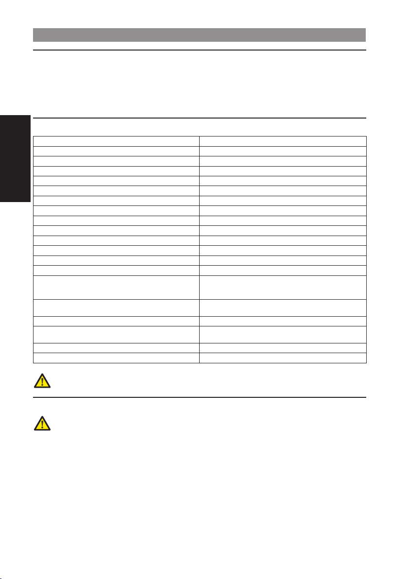
2. TECHNICAL SPECIFICATIONS
Power supply voltage 230 (+6% -10%) 50 Hz / 115 Vac 60 Hz
Supply voltage of control unit
Absorbed power 3 W
Motor nominal power 48 W
Accessories max. load 500 mA
ENGLISH
Flashing lamp max. load 15 W
Max. load for beam lights 15 W
Max. load for courtesy light/indicator light 5 W
Operating ambient temperature -20° +55°
Protective fuse F1=8 A F2=500 mA F3=630 mA (resettable)
Function logics Automatic - Condo - Semi-automatic
Opening / closing time Through self-learning during programming
Pause time Through self-learning during programming
Obstacle detection Trimmer-adjustable
Selectable functions
Terminal board inputs
Inputs with connector Battery kit - Radio connector
Terminal board outputs
Board dimensions 79 x 158 mm
Characteristics of optional batteries See kit on price list
a According to mains voltage, there may be different output values on the board power feed terminals.
Before putting into service, always check if the output voltage on the secondary winding of the transformer
is from 20 Vac to 26 Vac. Voltage must always be measured load free.
Type of logic - Operation of open command - No mains
power supplied function - Beam lights flashing - Safety
Power supply - Earth - Close - Open - Open/Close - Stop
Power supply for accessories - On beam lights - Indicator
24 Vac nominal a
devices behaviour
- Safety devices - Failsafe
light - Flashlight
3. PREPARATIONS
To ensure people’s safety, all warnings and instructions in this booklet must be carefully observed. Incorrect
installation or incorrect use of the product could cause serious harm to people.
Make sure that an adequate differential switch is installed upstream of the system as specified by current
•
regulations.
On the main power supply, install a thermal breaker with omnipolar switching.
•
Make sure that an adequate earthing system is available.
•
To lay cables, use adequate rigid and/or flexible tubes.
•
Always separate the connecting cables of low voltage accessories from those supplying 230/115 Vac, using
•
separate sheaths to avoid possible interference.
12
Page 3
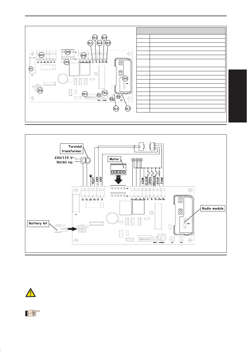
4. BOARD LAY-OUT
CN1 Power supply terminal-board
CN1 Power supply terminal-board
CN2 Commands terminal-board
CN2 Commands terminal-board
JP2 Battery kit connector
JP2 Battery kit connector
JP3 Connector for receiver module
JP3 Connector for receiver module
JP4 Power supply to RH closing motor
JP4 Power supply to RH closing motor
JP5 Power supply to LH closing motor
JP5 Power supply to LH closing motor
Trimmer for adjusting obstacle detection
Trimmer for adjusting obstacle detection
TR1
TR1
sensitivity
sensitivity
P1 Programming push-button
P1 Programming push-button
P2 OPEN channel memory storage push-button
P2 OPEN channel memory storage push-button
P3
OPEN/CLOSE channel memory storage push-button
P3
OPEN/CLOSE channel memory storage push-button
F1 Board protection fuse
F1 Board protection fuse
DL1 CLOSE contact LED
DL1 CLOSE contact LED
DL2 OPEN contact LED
DL2 OPEN contact LED
DL3 OPEN/CLOSE contact LED
DL3 OPEN/CLOSE contact LED
DL4 STOP contact LED
DL4 STOP contact LED
DL5 Photocells status LED
DL5 Photocells status LED
DL6 OPEN contact signalling LED
DL6 OPEN contact signalling LED
DL7 OPEN/CLOSE contact signalling LED
DL7 OPEN/CLOSE contact signalling LED
5. CONNECTION LAY-OUT
COMPONENTS
COMPONENTS
Fig. 1Fig. 1
ENGLISH
6. DESCRIPTION OF CONNECTIONS
6.1. TERMINAL BOARD CN1
6.1.1. power supply
Terminals “1 & 2”. The secondary winding wires of the toroidal transformer must be connected to these terminals.
Before making this connection, check if the voltage at the transformer output is in the range from 20 Vac to 26 Vac
6.1.2. eArthing
Terminal “3”. To this terminal, connect the earthing wire coming from the terminal inside the motor body.
The connection is absolutely necessary for correct operation of the control unit.
13
Fig. 2Fig. 2
Page 4

6.1.3. FAlsAFe
Terminal “4 ”. Connect to this terminal, the negative terminal of the photocell transmitters. By making this
connection, the control unit, before every manoeuvre, runs a test on the photocells, controlling correct operation. If
you use photocells, this terminal must be connected to ensure the control unit operates correctly.
6.1.4. power supply For Accessories
Terminals “5 & 6”. 24 Vdc output max. 500 mA for feeding the external accessories.
• Maximum load of this output is 500 mA.
• Observe the power supply polarity.
6.2. TERMINAL BOARD CN2
6.2.1. beAm lights
Terminals “7 & 10”. Output 24 Vdc max.15 W. The wires feeding the luminous strip should be connected to these
terminals. The operation of the luminous strip is defined by using dip-switch 5 - see paragraph 7.
Terminal “10” is the negative polarity output.
6.2.2. indicAtor light
Terminals “8 & 10”. Output 24 Vdc max. 5 W. An indicator light, if any, should be connected to these terminals. The
ENGLISH
indicator light makes it possible to see the beam status from a remote position, e.g. a porter’s lodge - details:
Beam opening is identified by fast flashing.
•
When the beam is open, the indicator light stays lighted on a steady light-beam.
•
Beam closing is identified by slow flashing.
•
When the beam is closed, the indicator light stays OFF.
•
• 24 Vdc max. 5 W lamps can be connected to this output.
• Terminal “10” is the negative polarity output.
6.2.3. FlAshing light
Terminals “9 & 10”. Output 24 Vdc max.15 W. A steady beam flashing light is connected to these terminals - flashing
is controlled by the control unit. The flashing light is active while the beam is moving, whereas when the beam is idle,
whether open or closed, it stays OFF. Pre-flashing of 0.5 sec was inserted before the beam opening manoeuvre, to
signal that the beam is about to move. In addition to signalling beam movement, the flashing light signals - by a
series of flashes - that the beam is being powered by the buffer battery (optional).
Terminal “10” is the negative polarity output.
6.2.4. close
Terminals “10 & 11”. Normally open contact. Connect, between these 2 terminals, any pulse generator (e.g.
push-button, key selector, etc..) which, by closing the contact, commands beam closure only. The status of this
input is signalled by LED “DL1”.
• The CLOSE command is not active during programming.
• If there are several pulse generators, they must be connected in parallel.
6.2.5. open
Terminals “10 & 12”. Normally open contact. Connect, between these 2 terminals, any pulse generator (e.g.
push-button, key selector, etc..) which, by closing the contact, commands beam opening only. The status of this
input is signalled by LED “DL2”.
• The OPEN command is not active during programming.
• If there are several pulse generators, they must be connected in parallel.
6.2.6. open / close
Terminals “10 & 13”. Normally open contact. Connect, between these 2 terminals, any pulse generator (e.g.
push-button, key selector, etc..) which, by closing the contact, commands beam opening and/or closing. The
behaviour of this input is defined by dip-switch 2, see paragraph 7. The status of this input is signalled by LED “DL3”.
• If there are several pulse generators, they must be connected in parallel.
6.2.7. stop
Terminals “10 & 14”. Normally closed contact. Connect, between these 2 terminals, any pulse generator (e.g.
push-button, key selector, etc..) which, by opening the contact, must command immediate stop of the beam and
the de-activation of any automatic re-closure. To resume the normal programmed cycle after this contact has been
activated, use any pulse generator which commands the opening and/or closing of the beam. The status of this
input is signalled by LED “DL4”.
• If there are several pulse generators, they must be connected in series.
14
Page 5

6.2.8. sAFety devices
Terminals “10 & 15”. Normally closed contact. Connect, to these terminals, any safety device (e.g. photocells)
which, by opening the contact, acts on beam motion. They can be active only during closure, or active in both
closing and opening, according to the position of dip-switch 6, see paragraph 7.
Safety devices active at closure
If the safety devices are activated during closure, the control unit immediately reverses beam movement until
opening is complete without disabling - if selected - automatic re-closing of the beam.
Safety devices active at closure and opening:
In this case the safety devices are active on both beam movements. If the safety devices are activated during
closure, the control unit immediately reverses beam movement until opening is complete without disabling - if
selected - automatic re-closing of the beam. If the safety devices are activated during opening, the control unit
immediately stops beam movement and keeps it stopped until the safety device is reset (obstacle removed), and
only then will the opening manoeuvre which had been started be resumed.
The status of this input is signalled by the LED located under the contact.
•If the safety devices are not used, a connection must be made between terminal 4 and terminal 15.
• If there are several safety devices, they must be connected in series.
6.3 MOTOR CONNECTION
The automated system is supplied designed for right hand closure, with the motor connected to connector JP4. For
left hand closure, the motor must be connected to connector JP5.
To identify beam closing direction, look at the automated system from the side of the release device. If the beam
has to descend on the left of the automated system in order to close, left hand closure is involved, vice-versa, if the
beam has to descend on the right of the automated system in order to close, right hand closure is involved.
Two motors cannot be connected to the same control unit.
6.4. BATTERY KIT
A battery kit can be connected to the board - see price list - to make up for a possible power cut.
For correct positioning of the battery kit inside the motor body, refer to the instruction for the mechanical part.
The battery kit must be connected to connector JP2.
7. DIP-SWITCH ADJUSTMENT
6 dip-switches are located on the control unit. They command the behaviour of the automated system and of the
safety devices connected to it. The behaviour of every dip-switch is summarised on the following table:
CONDO LOGIC
ON Condo logic activated
ON Condo logic activated
OFF Condo logic disabled
OFF Condo logic disabled
ON Open / Stop / Close / Stop ...
ON Open / Stop / Close / Stop ...
OFF Open / Close / Open .....
OFF Open / Close / Open .....
ON Automatic closing activated
ON Automatic closing activated
OFF Automatic closing disabled
OFF Automatic closing disabled
CONDO LOGIC
OPEN/CLOSE INPUT BEHAVIOUR
OPEN/CLOSE INPUT BEHAVIOUR
AUTOMATIC CLOSING
AUTOMATIC CLOSING
ENGLISH
OPEN BEAM (see paragraph 7.1)
ON Open beam function activated
ON Open beam function activated
OFF Open beam function disabled
OFF Open beam function disabled
ON
ON
OFF
OFF
ON Photocells ON both during closing and opening
ON Photocells ON both during closing and opening
OFF Photocells ON during closing only
OFF Photocells ON during closing only
OPEN BEAM (see paragraph 7.1)
BEAM LIGHT
Beam light ON when beam open and closed, flashing
Beam light ON when beam open and closed, flashing
while beam is moving.
while beam is moving.
Beam light OFF when beam open and closed, flashing
Beam light OFF when beam open and closed, flashing
while beam is moving.
while beam is moving.
BEAM LIGHT
PHOTOCELLS
PHOTOCELLS
15
Page 6

7.1. OPEN BEAM FUNCTION
With this function, combined or not with the battery kit, the following beam behaviour patterns are possible:
without bAttery kit
Dip-switch 4=OFF: If there is a mains power cut, the beam stays stopped in the position it is in. When mains power
returns, after 2 seconds the control unit automatically commands the beam to close, preparing itself for normal
operation.
Dip-switch 4=ON: If there is a mains power cut, the beam stays stopped in the position it is in. When mains power
returns, a pulse must be sent to ensure that the control unit resumes normal operation.
with bAttery kit
Dip-switch 4=OFF: If there is a mains power cut, the beam continues operating normally. At every opening, the
flashing light flashes twice consecutively, at intervals of 3 seconds between the flashes, for a maximum time of
30 seconds, signalling that the beam is battery powered. When mains power is resumed, the automated system
resumes normal operation.
The number of cycles possible with the automated system battery powered, depends on the battery
charge level, on the time elapsing since mains power was stopped, and on the conditions of the
automated system, external temperature etc...
Dip-switch 4=ON: In the event of a mains power cut, the automated system automatically opens the beam,
stopping it in vertical position and disabling all the commands. When mains power returns, if automatic logic
was selected, the automated system automatically performs a closing movement preparing itself for normal
ENGLISH
operation. Vice-versa, if manual logic was selected, the automated system waits for a pulse to resume normal
operation.
8. MEMORY STORING THE RADIO CODE
The control board has an integrated 2-channel decoding system (DS, SLH, LC) named OMNIDEC. This system makes
it possible to memory-store both OPEN command and the OPEN/CLOSE command of the automated system - this is
made possible by an additional receiver module and radio controls on the same frequency.
• The 3 types of radio codes (DS, LSH, LC) cannot coexist. Only one radio code can be used at a time. To
change over from one code to another, you must delete the existing one (see paragraph 8.3), and repeat
the memory-storage procedure.
• Fitting and, if necessary, removing the receiver module must be done only after cutting power to the board.
• The receiver module can only be inserted in one position. Orient the module correctly without forcing.
8.1. Memory storage of DS radio controls
A maximum of two codes can be stored. One on the OPEN channel and one on the OPEN/CLOSE channel.
On the DS radio control, select the required ON-OFF combination for the 12 dip-switches.
1.
On the control unit, press the push-button of the channel you wish to memory store, P2 for the OPEN channel or
2.
P3 for the OPEN/CLOSE channel.
The relevant LED on the control unit begins to flash - release the push-button.
3.
On the radio control, press the push-button with which you wish to associate the selected channel.
4.
The LED on the control unit lights up on steady beam for about one second, signalling that the radio control was
5.
stored in the memory, then it resumes flashing.
To add other radio controls or memory store the second channel, repeat the operations from point 1
6.
8.2. Memory storage of SLH radio controls
You can memory store up to a maximum of 250 codes, subdivided between the two channels, OPEN and
OPEN/CLOSE.
On the radio control, simultaneously press and hold down push-buttons P1 and P2 (see radio control instructions).
1.
After about one second, the LED of the radio control begins to flash.
2.
Release both push-buttons.
3.
Press and hold down push-button P2 or P3 on the board to respectfully memory store the OPEN or OPEN/CLOSE
4.
channel. The relevant LED begins to flash.
Simultaneously press the push-button of the radio control with which you wish to associate the selected
5.
command.
Check if the LED relating to the command being memory stored (DL6 for the OPEN channel or DL7 for the OPEN/
6.
CLOSE channel) lights up on steady beam for about two seconds to confirm correct memory storage.
To finish programming, press twice in close succession, the push-button of the memory stored radio control.
7.
The automated system will perform an opening manoeuvre - make sure that there are no obstacles inside the
operating range.
To memory store the other channel, repeat all the procedure from point 1.
8.
To add other radio controls, transfer the code of the memory-stored push-button of the radio control to the relevant
push-button of the radio controls to be added, repeating the memory storage procedure or observing the following
procedure:
On the memory stored radio control, simultaneously press and hold down push-buttons P1 and P2 (see radio
•
control instructions).
The radio control LED begins to flash.
•
Release both push-buttons.
•
16
Page 7

Put the two radio controls frontally into contact.
•
On the memory stored radio control, press and hold down the push-button relating to the channel you wish to
•
transfer - the radio control LED lights up on steady beam.
On the radio control to be memory stored, press the required push-button and release it after the radio control has
•
flashed twice.
To finish programming, press twice in close succession, the push-button of the memory stored radio control.
•
The automated system will perform an opening manoeuvre - make sure that there are no obstacles inside the
operating range.
8.3. Memory storage of LC radio controls
You can memory store up to a maximum of 250 codes, subdivided between the two channels, OPEN and
OPEN/CLOSE.
Use LC remote controls only with receiver module at 433 MHz.
1.
On the control unit, press the push-button of the channel you wish to memory store, P2 for the OPEN channel or
2.
P3 for the OPEN/CLOSE channel.
The relevant LED on the control unit begins to flash - release the push-button.
3.
On the radio control, press the push-button with which you wish to associate the selected channel.
4.
The LED on the control unit lights up on steady beam for about one second, signalling that the radio control was
5.
stored in the memory, then it resumes flashing.
During this stage further radio controls can be stored in the memory.
6.
After about 10 seconds, the control unit automatically exits the learning stage.
7.
To add other radio controls or memory store the second channel, repeat the operations from point 1
8.
8.3.1. remote memory storAge oF lc rAdio controls
Other radio controls can be remotely stored only with the LC radio controls, i.e. without using the push-buttons of the
control unit,, but using a previously stored radio control.
Get a radio control already memory stored on one of the 2 channels.
1.
Step near to the automated system.
2.
Press and hold down push-buttons P1 and P2 (see radio control instructions) simultaneously for about 5 seconds.
3.
Within 5 seconds, press, on the memory stored radio control , the push-button you wish to transfer to the new
4.
radio control. In this way the learning stage on the selected channel is activated on the control unit.
Within 5 seconds, press, on the new radio control, the push-button you wish to associate with the selected
5.
channel.
After the new radio control has been stored in the memory, the control unit keeps the learning mode active on
6.
the selected channel for about 5 seconds.
During these 5 seconds, other radio controls can be memory stored on the control unit, as ever associated with
7.
the activated channel.
When 5 seconds have elapsed from memory-storage of the last radio control, the control unit automatically
8.
exits the learning stage.
To check if the radio control was correctly memory stored, wait for 5 seconds after sending the code.
9.
8.4. Deletion of radio codes
To delete all the radio controls stored in the memory, go through the following procedure:
Press and hold down one of the two push-buttons P2 or P3.
1.
The relevant LED begins to flash.
2.
After five seconds, the LED starts to flash at high speed.
3.
After another five seconds both LEDS, DL6 and DL7 light up on steady beam.
4.
Release the push-button.
5.
This operation is irreversible, and all radio controls associated with both the OPEN and the OPEN/CLOSE
command will be deleted.
ENGLISH
9. OBSTACLE DETECTION SENSITIVITY
The obstacle detection device enables the control unit to detect any obstacles while the beam is moving. As this is
an electronic device, it stays constant through time and is not subject to variations - this guarantees an automated
system with a constant safety level.
By using the TR1 trimmer, you can increase or reduce the obstacle detection sensitivity. Turn the trimmer clockwise to
increase detection sensitivity, vice-versa turn it anti-clockwise to reduce obstacle detection sensitivity.
This device is active both during the beam closing stage and during the beam opening stage.
If it operates during the opening stage, it stops the operation of the automated system and reverses motion for 1
second. At this point, a pulse must be sent to the control unit, to resume normal programmed operation.
If it operates during the closing stage, it reverses operation until the automated system is completely open without
disabling any automatic closing.
If it operates three times in succession, it blocks the operation of the automated system and locates itself in stop
position, disabling automatic closing, if it was activated. To restore normal operation, you must command the beam
to open or close. Behaviour patterns will differ, according to the command sent:
OPEN or OPEN/CLOSE pulse: In this case, the beam starts an opening manoeuvre at slower speed until the beam is
completely open. When complete opening has been reached, the beam resumes its normal operating cycle,
re-activating automatic re-closing, if it had been enabled.
CLOSE pulse: In this case, the beam starts a closing manoeuvre at slower speed until the beam is completely closed.
When closed, the beam resumes its normal operating cycle, re-activating automatic re-closing, if it had been
enabled.
17
Page 8

10. PROGRAMMING
When the control unit is first powered up, a programming cycle must be performed. The board keeps all
commands disabled, with the exception of programming push-button P1, and of the pulse generators
connected to the OPEN/CLOSE input
When you have made the connections of all the accessories and generators, program the operating cycle.
To program the control unit, follow the instructions below:
Turn the differential switch of the control unit, to make sure that the automated system is not powered.
1.
Release the automated system, using the release device - see instructions for the mechanical part - and position
2.
the beam at about half of its opening angle (45°).
Re-lock the beam and make sure that it cannot be moved manually.
3.
Power up the system.
4.
Press P1 for about 1 second, the flashing lamp goes on at steady beam.
5.
Supply an OPEN/CLOSE command by means of any device connected to this input: the beam starts moving.
6.
The first manoeuvre the beam carries out is in closing. If the automated system starts an opening manoeuvre,
check if the motor connector is correctly connected, as described in paragraph 6.3.
Restore power and repeat the procedure from point 5.
7.
When the closing mechanical stop is reached, the beam begins the opening manoeuvre.
8.
When maximum opening is achieved, the pause time count for automatic re-closure begins.
9.
When the required time has elapsed, supply another OPEN/CLOSE pulse, and the automated system will begin
10.
the closing stage.
ENGLISH
When the closing position is reached, the flashing lamp goes off and programming has finished.
11.
During the programming procedure, the beam moves more slowly and the safety devices are disabled.
11. CONTROL LEDs
There are 7 control LEDs on the control unit. The meanings of the LEDs are shown on the table below:
INPUT LEDS
LED ON OFF
DL1 - CLOSE Input Active command Inactive command
DL2 - OPEN input Active command Inactive command
DL3 - OPEN/CLOSE input Active command Inactive command
DL4 - STOP input Inactive command Active command
DL5 - FSW input Safety devices free Safety devices engaged
PROGRAMMING LEDS
LED ON OFF
DL6 - OPEN channel Active input Inactive input
DL7 - OPEN/CLOSE channel Active input Inactive input
The bold print indicates the condition of the LEDs with the control unit powered up and the beam closed in
rest position.
18
Page 9

commands
Disables OPEN
at release resets
Disables commands
pause time
opens at release
restarts after release
Stops movement and
Stops movement and
commands
Disables OPEN
Disables commands
opens at release
restarts after release
Stops movement and
Stops movement and
PHOTOCELLS
STOP
INPUTS
OPEN / CLOSE
No effect
it disables all
No effect (if active,
Opens and re-closes
pause time
at release resets
Disables commands
commands)
Stops operation
after pause time
Reverses motion on
Re-closes immediately
opening
Reverses motion on
Stops operation No effect
Stops operation
closing
opening
Reverses motion on
PHOTOCELLS
STOP
INPUTS
OPEN / CLOSE
No effect
Disables all
commands
commands)
it disables all
No effect (if active,
Stops operation No effect
closing
Reverses motion on
opening
Reverses motion on
ENGLISH
Stops operation
opening
Reverses motion on
12. FUNCTION LOGICS
LOGIC A (Automatic) DIP-SWITCH 1=ON / DIP-SWITCH 3=OFF
DIP-SWITCH 2=ON DIP-SWITCH 2=OFF DIP-SWITCH 6=OFF DIP-SWITCH 6=ON
Opens and re-closes
after pause time
Stops operation and,
at next pulse, closes
at next pulse, opens
Stops operation and,
LOGIC E (Semi-automatic) DIP-SWITCH 1=OFF / DIP-SWITCH 3=OFF
DIP-SWITCH 2=ON DIP-SWITCH 2=OFF DIP-SWITCH 6=OFF DIP-SWITCH 6=ON
BARRIER STATUS
OPEN CLOSE
No effect
after pause time
Opens and re-closes
CLOSED
OPEN IN PAUSE Reloads pause time Closes immediately Stops operation
AT OPENING No effect Closes
AT CLOSING Reverses on opening No effect
19
BARRIER STATUS
OPEN CLOSE
CLOSED Opens No effect Opens Opens
OPEN No effect Closes immediately Re-closes immediately Re-closes immediately Stops operation
AT CLOSING Reverses on opening No effect Stops operation
AT OPENING No effect Closes Stops operation
Page 10

Disables OPEN
PHOTOCELLS
pause time
commands
Disables commands
and at release resets
Stops movement and
opens at release
restarts after release
Stops movement and
ENGLISH
INPUTS
LOGIC CN (Condo) DIP-SWITCH 1=ON / DIP-SWITCH 3=ON
No effect
STOP
it disables all
No effect (if active,
Opens and re-closes
OPEN / CLOSE
DIP-SWITCH 2=ON DIP-SWITCH 2=OFF DIP-SWITCH 6=OFF DIP-SWITCH 6=ON
Opens and re-closes
No effect
pause time
Disables commands
and at release resets
commands)
after pause time
after pause time
Reverses motion on
opening
Reverses motion on
Stops operation
opening
Reverses motion on
opening
No effect No effect Stops operation No effect
Reverses motion on
closing
BARRIER STATUS
OPEN CLOSE
after pause time
Opens and re-closes
CLOSED
OPEN IN PAUSE Reloads pause time Closes immediately Reloads pause time Re-closes immediately Stops operation
20
AT CLOSING Reverses on opening No effect
AT OPENING No effect
 Loading...