

Page 1
E391
Page 2

Page 3
INDICE
1 AVVERTENZE ..................................................................................................................2
2 LAYOUT E COLLEGAMENTI .............................................................................................2
3 CARATTERISTICHE TECNICHE ..........................................................................................3
3.1 DESCRIZIONE COMPONENTI .................................................................................................3
3.2 DESCRIZIONE MORSETTIERE ..................................................................................................3
3.3 FUNZIONE ANTI-SCHIACCIAMENTO .........................................................................................3
4 PROGRAMMAZIONE DELLA LOGICA .............................................................................3
5 PROGRAMMAZIONE DELLA VELOCITA’ ...........................................................................3
6 MESSA IN FUNZIONE ......................................................................................................4
6.1 VERIFICA DEI LED ................................................................................................................. 4
6.2 PROGRAMMAZIONE DIP-SWITCH .........................................................................................4
6.3 PRELAMPEGGIO ....................................................................................................................4
6.4 APPRENDIMENTO TEMPI - SETUP ..........................................................................................4
6.4.1 SETUP AUTOMATICO ......................................................................................................................4
6.4.2 SETUP MANUALE ............................................................................................................................4
7 INSTALLAZIONE ACCESSORI BUS ...................................................................................5
7.1 INDIRIZZAMENTO FOTOCELLULE BUS ...................................................................................5
7.2 MEMORIZZAZIONE ACCESSORI BUS ....................................................................................6
8 MEMORIZZAZIONE CODIFICA RADIO ............................................................................6
8.1 MEMORIZZAZIONE DEI RADIOCOMANDI DS ......................................................................... 6
8.2 MEMORIZZAZIONE DEI RADIOCOMANDI SLH ........................................................................ 6
8.3 MEMORIZZAZIONE DEI RADIOCOMANDI LC (solo per alcuni mercati) ............................... 7
8.3.1 MEMORIZZAZIONE REMOTA RADIOCOMANDI LC ........................................................................7
8.4 PROCEDURA DI CANCELLAZIONE DEI RADIOCOMANDI ........................................................7
9 COLLEGAMENTO BATTERIE TAMPONE (OPTIONAL)
10 PROVA DELL’AUTOMAZIONE ..........................................................................................7
11 TABELLE DELLE LOGICHE ................................................................................................8
...............................................................7
ITALIANO
DICHIARAZIONE CE DI CONFORMITÁ
Fabbricante: FAAC S.p.A.
Indirizzo: Via Benini, 1 - 40069 Zola Predosa BOLOGNA - ITALIA
Dichiara che: L’apparecchiatura elettronica E391
•·è conforme ai requisiti essenziali di sicurezza delle seguenti direttive CEE
2006/95/CE Direttiva Bassa Tensione
2004/108/CE Direttiva Compatibilità Elettromagnetica
Nota aggiuntiva:
Questo prodotto è stato sottoposto a test in una configurazione tipica omogenea (tutti prodotti di costruzione FAAC S.p.A.).
Bologna, 01-07-2008
L’Amministratore Delegato
A. Marcellan
AVVERTENZE
• Attenzione! È importante per la sicurezza delle persone seguire attentamente tutta l’istruzione.
• Una errata installazione o un errato uso del prodotto può portare a gravi danni alle persone.
• Leggere attentamente le istruzioni prima di iniziare l’installazione del prodotto e conservarle per riferimenti futuri.
• Il simbolo evidenzia le note importanti per la sicurezza delle persone e l’integrità dell’automazione.
• Il simbolo richiama l’attenzione sulle note riguardanti le caratteristiche od il funzionamento del prodotto.
1
Page 4
APPARECCHIATURA ELETTRONICA E391
1 AVVERTENZE
Prima di effettuare qualsiasi tipo di intervento sull’apparecchiatura elettronica (collegamenti, manutenzione)
togliere sempre l’alimentazione elettrica.
- Prevedere a monte dell’impianto un interruttore magnetotermico differenziale con adeguata soglia di intervento.
ITALIANO
- Separare sempre i cavi di alimentazione da quelli di comando e di sicurezza (pulsante, ricevente, fotocellule, ecc.).
- Per evitare qualsiasi disturbo elettrico utilizzare guaine separate o cavo schermato (con schermo collegato a massa).
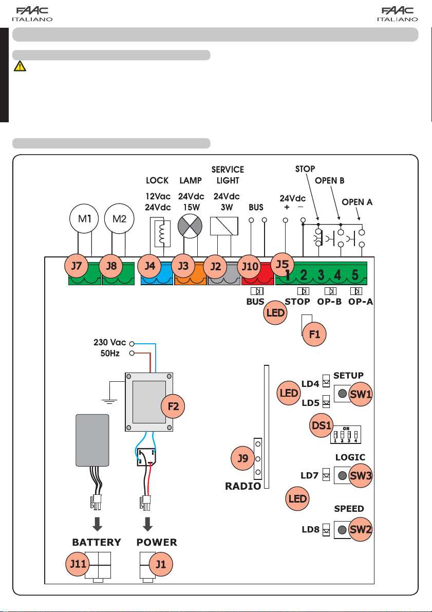
2 LAYOUT E COLLEGAMENTI
(APERTURA PARZIALE)
(APERTURA TOTALE)
Fig. 1
2
Page 5
3 CARATTERISTICHE TECNICHE
Tensione alimentazione
Potenza assorbita
Carico max Motore
Corrente max accessori
(+24V)
Corrente max accessori
BUS
Temperatura ambiente
Fusibili di protezione
Logiche di funzionamento
Tempo di lavoro (timeout)
Tempo di pausa
Ingressi in morsettiera
Ingressi in connettore
Uscite in morsettiera
Funzioni programmabili
Funzioni apprendimento
Tipologia canali radio
integrati
3.1 DESCRIZIONE COMPONENTI
Connettore ALIMENTAZIONE
J1
Morsettiera comando LUCE DI SERVIZIO
J2
Morsettiera LAMPEGGIANTE
J3
Morsettiera ELETTROSERRATURA
J4
Morsettiera COMANDI
J5
Morsettiera MOTORE 1
J7
Morsettiera MOTORE 2
J8
Innesto rapido MODULO XF
J9
Morsettiera BUS
J10
Connettore BATTERIA
J11
Pulsante SETUP
SW1
Pulsante SPEED
SW2
Pulsante LOGIC
SW3
Dip-switch programmazione
DS1
Fusibile protezione accessori
F1
Fusibile protezione trasformatore e motori
F2
LEDs di segnalazione
LED
230Vac (+6% -10%) - 50Hz
-20°C ÷ +55°C
F1 = autoripristinante;
F2 = T2A-250V
1 minuto (fisso)
Variabile in base all’apprendi-
Open A, Open B, Stop, BUS (I/O)
Alimentazione, batteria,
modulo XF433 o XF868
Motori, lampeggiante, alimenta-
zione accessori, elettroserratura,
contatto luce di servizio (90 sec
Logica (A, EP), Velocità (alta 13°/
sec e bassa 10°/sec)
Tempo di pausa, ritardo anta 2 in
DS, SLH (max 250 canali)
LC (max 250 canali - SOLO PER
ALCUNI MERCATI)
10W
150W x 2
250 mA
400 mA
EP, A
mento
(max 10 min)
fisso)
chiusura
3.2 DESCRIZIONE MORSETTIERE
Morsetto e/o Morsettiera Descrizione Dispositivo collegato
1
+24V
Alimentazione accessori
2 GND Negativo
Dispositivo con
3 STOP
J5
4 OPEN B
5 OPEN A
J10
Morsetto ROSSO
J2
Morsetto GRIGIO
J3
Morsetto ARANCIONE
J4
Morsetto AZZURRO
SERVICE
LIGHT
LAMP
LOCK
contatto N.C. che
provoca il blocco
dell’automazione
Dispositivo con contatto N.A. (vedi cap.
LOGICHE FUNZIONAMENTO)
Dispositivi di sicurezza
BUS
con tecnologia BUS
Uscita comando
Luce di servizio (collegare una bobina
relay a 24Vdc-100mA
max)
Lampeggiante
24Vdc - 15W
Elettroserratura
12Vac oppure 24Vdc
(da installare su anta 1)
J7 MOT1 Motore 1 (anta 1)
J8 MOT2 Motore 2 (anta 2)
Per anta 1 si intende l’anta che apre per prima
in apertura.
Il comando luce di servizio è attivo durante
tutta la movimentazione in apertura o chiusura
cancello e per i successivi 90 secondi.
3.3 FUNZIONE ANTI-SCHIACCIAMENTO
Qualora il cancello incontri un ostacolo durante il movimento
di apertura o chiusura, la funzione anti-schiacciamento si attiva
invertendo il senso di marcia dell’operatore ed aumentando
di fatto il grado di sicurezza dell’automazione.
La sensibilità dell’anti-schiacciamento può essere regolata con
l’utilizzo del dip-switch n°3 (vedi par. 6.2).
4 PROGRAMMAZIONE DELLA LOGICA
La logica di funzionamento può essere selezionata in qualsiasi
momento premendo il pulsante SW3.
La logica selezionata viene poi visualizzata dal led LD7:
Led acceso = logica AUTOMATICA (A)
Led spento = logica SEMIAUTOMATICA PASSO-PASSO (EP)
5 PROGRAMMAZIONE DELLA VELOCITA’
La velocità di funzionamento può essere regolata in qualsiasi
momento premendo il pulsante SW2.
La logica selezionata viene poi visualizzata dal led LD8:
Led acceso = velocità ALTA (13 °/sec)
Led spento = velocità BASSA (10 °/sec)
3
ITALIANO
Page 6
6 MESSA IN FUNZIONE
6.1 VERIFICA DEI LED
La tabella sottostante riporta lo stato dei leds in relazione allo
stato degli ingressi (in neretto la condizione di automazione
chiusa a riposo).
Verificare lo stato dei leds di segnalazione come dalla tabella
seguente.
ITALIANO
Tab. 1 - Funzionamento leds di segnalazione stato ingressi
LED ACCESO (contatto chiuso) SPENTO (contatto aperto)
STOP Comando inattivo Comando attivo
OPEN A Comando attivo Comando inattivo
OPEN B Comando attivo Comando inattivo
BUS Vedi par. 7.2
6.2 PROGRAMMAZIONE DIP-SWITCH
Nella tabelle seguente sono riportate le impostazione del
dip-switch DS1 per la programmazione della forza, del
prelampeggio e del colpo d’inversione.
Tab. 2 - Programmazione DS1 (in neretto le impostazioni di
default)
DS1 DS2 DS3 DS4 Descrizione
ON ON FORZA ALTA
ON OFF FORZA MEDIO ALTA
OFF ON FORZA MEDIO BASSA
OFF OFF FORZA BASSA
ON ANTIVENTO ON
OFF ANTIVENTO OFF
ON COLPO D’INVERSIONE ON
OFF COLPO D’INVERSIONE OFF
Se si collega un’elettroserratura al morsetto
J4, posizionare il DS4 su ON affinché venga
abilitato il colpo d’inversione (prima dell’apertura i motori spingono in chiusura, facilitando
lo sgancio dell’elettroserratura).
Impostando su ON il dip-switch DS3 si attiva
una speciale funzione antivento che permette
al cancello di lavorare anche in presenza di
raffiche di vento.
6.4 APPRENDIMENTO TEMPI - SETUP
Prima di eseguire qualsiasi manovra è neces-
sario eseguire un ciclo di SETUP
Durante la procedura di SETUP non interrompe-
re le fotocellule, in quanto la loro interruzione
provoca l’arresto immediato delle ante. Per
terminare la procedura occorre eseguire l’apprendimento dall’inizio.
Quando si alimenta la scheda e non è mai stato eseguito un
ciclo di SETUP, i leds LD4 e LD5 iniziano a lampeggiare lentamente a segnalare la necessità di eseguire un ciclo di SETUP.
Sono disponibili due tipologie di SETUP: AUTOMATICO e MA-
NUALE
6.4.1 SETUP AUTOMATICO
Per eseguire il SETUP AUTOMATICO seguire la procedura seguente:
Portare le ante a metà apertura.
1.
Tener premuto il pulsante SETUP (SW1) fino a quando i 2 led
2.
adiacenti (LD4 e LD5) si accedono fissi.
Rilasciare il pulsante SETUP, i leds LD4 e LD5 iniziano a lam-
3.
peggiare velocemente.
L’anta 2 (se presente) inizia il movimento di chiusura fer-
4.
mandosi al raggiungimento della battuta meccanica di
chiusura.
L’anta 1 inizia il movimento di chiusura fermandosi al rag-
5.
giungimento della battuta meccanica di chiusura.
L’anta 1 inizia il movimento di apertura.
6.
L’anta 2 (se presente) inizia il movimento di apertura dopo
7.
un ritardo fisso in apertura.
Le ante 1 e 2 (se presente) si arrestano al raggiungimento
8.
della battuta meccanica di apertura.
Attendere che i leds LD4 e LD5 si spengano a significare
9.
che la procedura di SETUP è terminata.
Dare un impulso di OPEN per far chiudere il cancello.
10.
Una volta avviata la procedura di SETUP se le
ante al punto 4 e 5 aprono anziché chiudere
occorre invertire i cavi di alimentazione dei
motori.
Con il SETUP AUTOMATICO gli spazi di rallenta-
mento, i ritardi d’anta in apertura e chiusura
e il tempo pausa (30 sec, con logica A) sono
prefissati dalla scheda e non si possono modificare.
6.3 PRELAMPEGGIO
E’ possibile attivare e disattivare la funzione di prelampeggio
(in seguito a un comando di OPEN, l’apparecchiatura attiva
il lampeggiatore per 3 secondi prima di iniziare il movimento)
agendo come di seguito descritto:
Premere per almeno 5 sec il tasto LOGIC (SW3) per ATTIVARE
1.
il prelampeggio.
Premere per almeno 5 sec il tasto SPEED (SW2) per DISAT-
2.
TIVARE il prelampeggio.
In entrambi i casi verificare che il led relativo
al tasto premuto non cambi di stato, altrimenti
si è variata la funzione relativa al tasto e non
il prelampeggio.
6.4.2 SETUP MANUALE
Per eseguire il SETUP MANUALE seguire la procedura seguente:
Portare le ante a metà.
1.
Tener premuto il pulsante SETUP (SW1) fino a quando le
2.
ante iniziano a muoversi.
Rilasciare il pulsante SETUP, i leds LD4 e LD5 iniziano a lam-
3.
peggiare velocemente
L’anta 2 (se presente) inizia il movimento di chiusura fer-
4.
mandosi al raggiungimento della battuta meccanica di
chiusura
L’anta 1 inizia il movimento di chiusura fermandosi al rag-
5.
giungimento della battuta meccanica di chiusura
L’anta 1 inizia il movimento di apertura.
6.
L’anta 2 (se presente) inizia il movimento di apertura dopo
7.
un ritardo fisso in apertura.
4
Page 7
8.
Le ante 1 e 2 (se presente) si arrestano al raggiungimento
della battuta meccanica di apertura.
Se è stata impostata la forza BASSA attendere circa 5 sec
9.
verificando lo spegnimento del lampeggiante.
Nel caso sia selezionata la logica A la scheda inizia il con-
10.
teggio del tempo di pausa (max 10 min) e dopo il tempo
desiderato dare un impulso di OPEN per continuare la
procedura. Altrimenti se si seleziona la logica EP le ante
iniziano a richiudere immediatamente come riportato al
punto successivo.
L’anta 2 (se presente) inizia il movimento di chiusura e la
11.
scheda inizia il conteggio del ritardo d’anta in chiusura.
Trascorso il ritardo desiderato dare un impulso di OPEN per
12.
far iniziare all’anta 1 il movimento di chiusura.
Le ante 1 e 2 (se presente) si arrestano al raggiungimento
13.
della battuta meccanica di chiusura.
Attendere che i leds LD4 e LD5 si spengano a significare
14.
che la procedura di SETUP è terminata.
Una volta avviata la procedura di SETUP se le
ante al punto 4 e 5 aprono anziché chiudere
occorre invertire i cavi di alimentazione dei
motori.
Con il SETUP MANUALE gli spazi di rallentamento,
i ritardi d’anta in apertura sono prefissati dalla
scheda e non si possono modificare. Mentre il
ritardo d’anta in chiusura e il tempo pausa sono
programmabili durante l’apprendimento.
7 INSTALLAZIONE ACCESSORI BUS
Questa scheda è provvista di circuito BUS che consente di collegare facilmente un elevato numero di accessori BUS (ad es.
fino a 16 coppie di fotocellule), opportunamente programmati,
utilizzando solamente due cavi senza polarità.
Di seguito è descritto l’indirizzamento e la memorizzazione
delle fotocellule BUS.
Per altri futuri accessori riferirsi alle istruzioni specifiche.
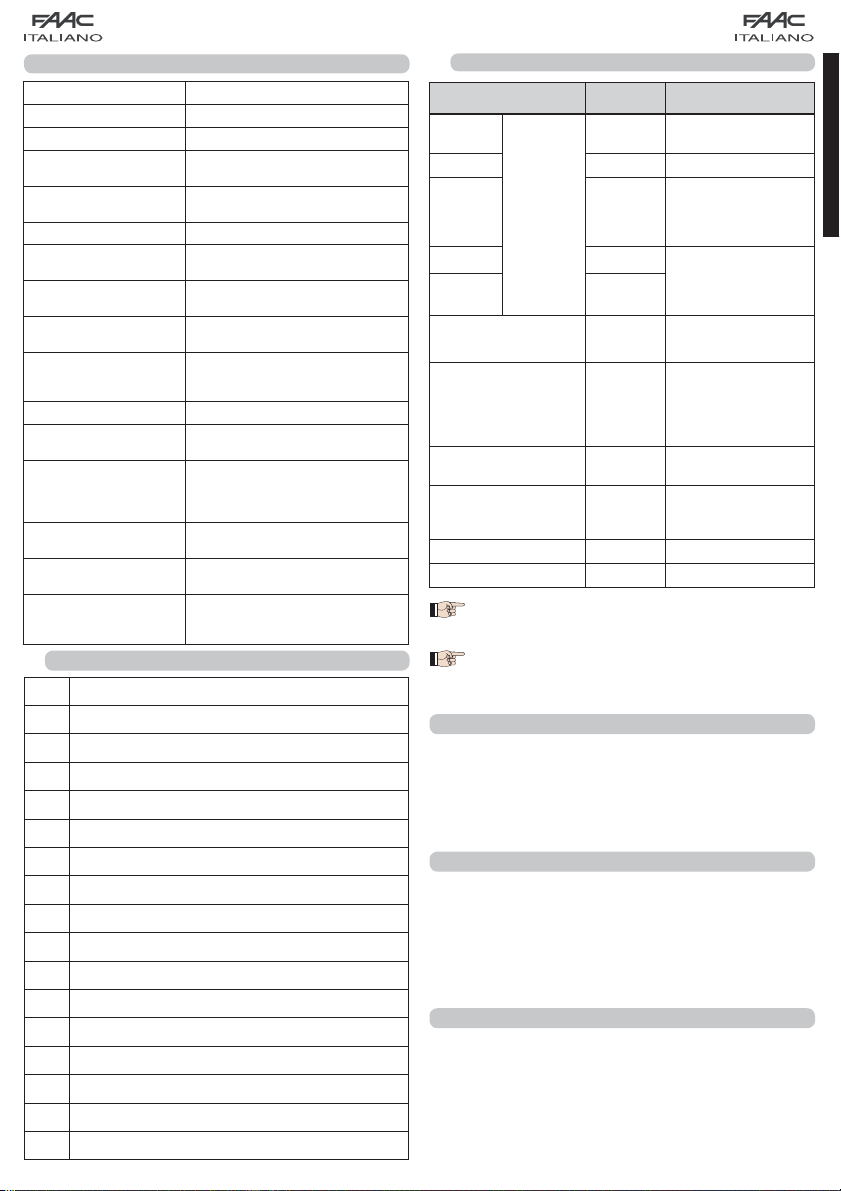
7.1 INDIRIZZAMENTO FOTOCELLULE BUS
È importante dare sia al trasmettitore sia al
ricevitore lo stesso indirizzo.
Accertarsi che non vi siano due o più coppie
di fotocellule con lo stesso indirizzo
Se non si utilizza alcun accessorio BUS, lasciare
libero il connettore BUS (J10 - fig. 1).
Alla scheda possono essere collegati fino ad un massimo di
16 coppie di fotocellule BUS.
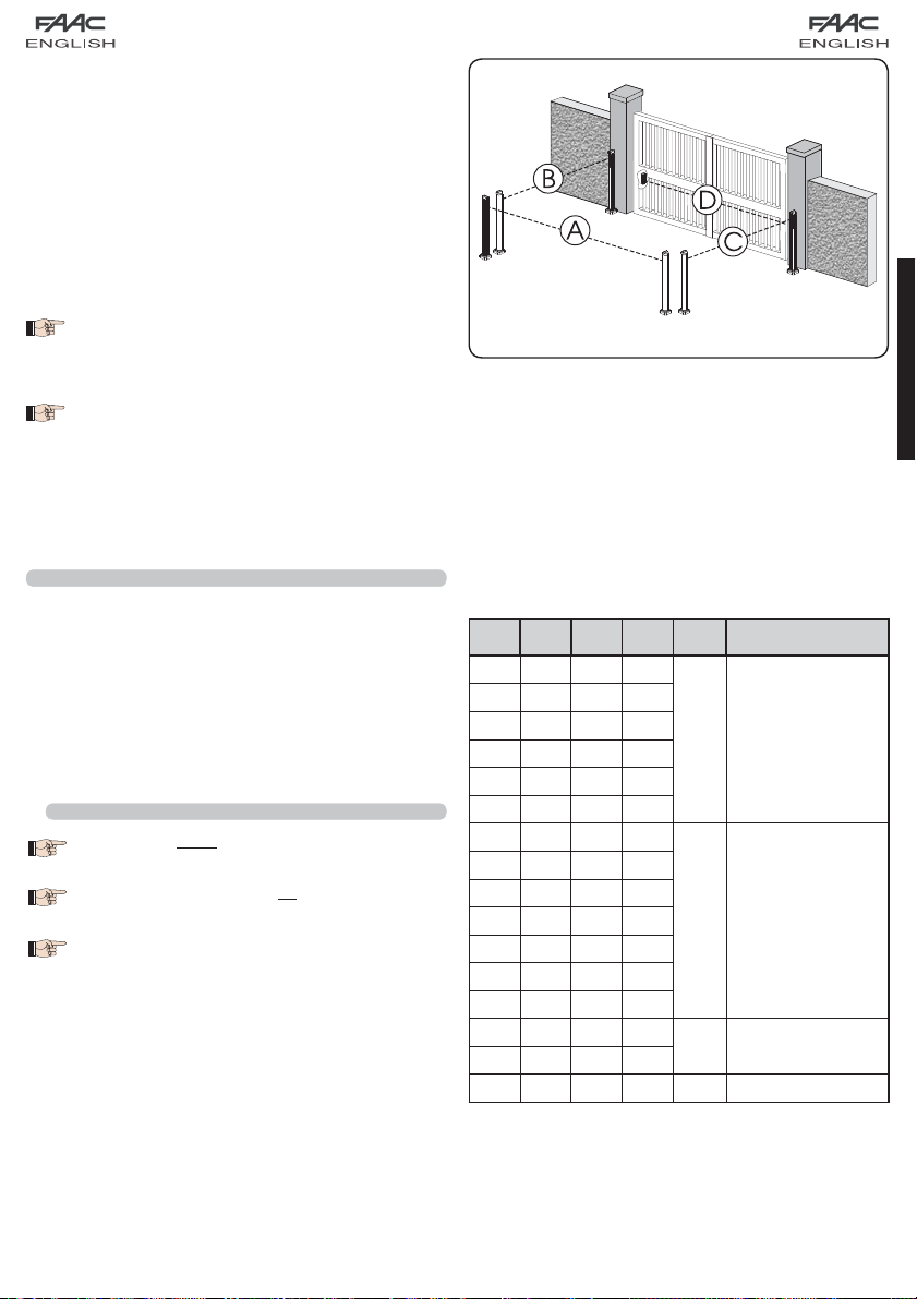
Le fotocellule sono suddivise in gruppi:
Fotocellule in apertura: max 6
Fotocellule in chiusura: max 7
Fotocellule in apertura/chiusura: max 2
Fotocellula usata come impulso OPEN: max 1
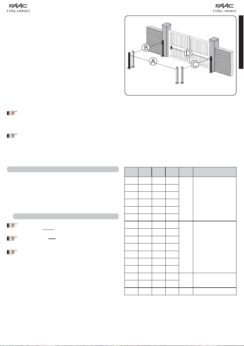
Fig. 2
In fig. 2 è rappresentato un’automazione a battente 2 ante
con indicati i fasci di copertura delle fotocellule:
A: Fotocellule con intervento in APERTURA e CHIUSURA
B: Fotocellule con intervento in APERTURA
C: Fotocellule con intervento in APERTURA
D: Fotocellule con intervento in CHIUSURA
In tab. 3 sono riportate le programmazioni del dip-switch
presente all’interno del trasmettitore e del ricevitore delle fotocellule BUS.
Tab. 3 - Indirizzamento fotocellule BUS
Dip1 Dip2 Dip3 Dip4 Rif. Tipologia
OFF OFF OFF OFF
OFF OFF OFF ON
OFF OFF ON OFF
OFF OFF ON ON
OFF ON ON OFF
OFF ON ON ON
ON OFF OFF OFF
ON OFF OFF ON
ON OFF ON OFF
ON OFF ON ON
ON ON OFF OFF
ON ON OFF ON
ON ON ON OFF
OFF ON OFF OFF
OFF ON OFF ON
ON ON ON ON / IMPULSO OPEN
B - C APERTURA
D CHIUSURA
A
APERTURA e
CHIUSURA
ITALIANO
5
Page 8
7.2 MEMORIZZAZIONE ACCESSORI BUS
In qualsiasi momento è possibile aggiungere fotocellule BUS
all’impianto, semplicemente memorizzandole sulla scheda
seguendo la seguente procedura:
Installare e programmare gli accessori con l’indirizzo desi-
1.
derato (vedi par. 7.1).
Togliere alimentazione alla scheda.
2.
ITALIANO
Collegare i due cavi degli gli accessori alla morsettiera
3.
rossa J10 (polarità indifferente).
Alimentare la scheda, avendo cura di collegare prima
4.
l’alimentazione principale (uscita trasformatore) e in seguito
le eventuali batterie.
Premere rapidamente una volta il pulsante SW1 (SETUP) per
5.
eseguire l’apprendimento. Il led BUS farà un lampeggio.
Dare un impulso di OPEN, il cancello effettuerà una mo-
6.
vimentazione, la procedura di memorizzazione è terminata.
La scheda ha memorizzato gli accessori BUS. Seguire le indicazione della tabella seguente per controllare il buono stato
del collegamento BUS.
Tab. 4 - Descrizione led BUS
Acceso fisso
Lampeggiante
lento
(flash ogni
0,5 sec)
Spento
(flash ogni 2,5
sec)
Lampeggiante
(flash
veloce
ogni 0,2 sec)
Funzionamento regolare (led acceso
anche in assenza di fotocellule)
Almeno un ingresso impegnato: fotocellula impegnata o non allineata, ingressi
Open A o Open B o Stop impegnati
Linea BUS in cortocircuito
Rilevato errore nel collegamento BUS,
ripetere la procedura di acquisizione.
Se l’errore si ripresenta controllare che
nell’impianto non ci sia più di un accessorio con lo stesso indirizzo (vedi anche
istruzioni relativa agli accessori)
8 MEMORIZZAZIONE CODIFICA RADIO
L’apparecchiatura elettronica è provvista di un sistema di decodifica (DS, SLH, LC) bi-canale integrato chiamato OMNIDEC.
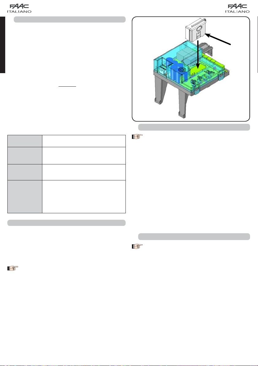
Questo sistema permette di memorizzare, tramite un modulo
ricevente aggiuntivo (Fig. 3 rif. /) e radiocomandi della stessa
frequenza , sia l’apertura totale (OPEN A) sia l’apertura parziale
(OPEN B) dell’automazione.
Le 3 tipologie di codifica radio (DS, SLH, LC)
non possono coesistere.
Sarà possibile utilizzare una sola codifica radio
per volta.
Per passare da una codifica all’altra occorre
cancellare quella esistente (vedere paragrafo
relativo alla cancellazione), e ripetere la procedura di memorizzazione.
8.1 MEMORIZZAZIONE DEI RADIOCOMANDI DS
E’ possibile memorizzare max. 2 codici. Uno sul
canale OPEN A ed uno sul canale OPEN B
Sul radiocomando DS scegliere la combinazione ON - OFF
1.
desiderata dei 12 dip-switches.
Premere il pulsante LOGIC (SW3) o SPEED (SW2), per memo-
2.
rizzare rispettivamente l’apertura totale (OPEN A) o quella
parziale (OPEN B), e mantenendolo premuto premere
anche il pulsante SETUP (SW1). Il led corrispondente inizierà
a lampeggiare lentamente per 5 sec.
Rilasciare entrambi i pulsanti.
3.
Entro questi 5 sec. premere il pulsante desiderato sul ra-
4.
diocomando.
Il led corrispondente si accenderà fisso per 1 secondo
5.
per poi spegnersi, indicando l’avvenuta memorizzazione.
Per aggiungere altri radiocomandi è necessario impostare
6.
la stessa combinazione ON - OFF utilizzata al punto 1.
8.2 MEMORIZZAZIONE DEI RADIOCOMANDI SLH
E’ possibile memorizzare max. 250 codici, divisi
fra OPEN A ed OPEN B.
Sul radiocomando SLH premere e tenere premuti i pulsanti
1.
P1 e P2 contemporaneamente.
Il led del radiocomando inizierà a lampeggiare.
2.
Lasciare entrambi i pulsanti.
3.
Premere il pulsante LOGIC (SW3) o SPEED (SW2), per memo-
4.
rizzare rispettivamente l’apertura totale (OPEN A) o quella
parziale (OPEN B), e mantenendolo premuto premere
anche il pulsante SETUP (SW1). Il led corrispondente inizierà
a lampeggiare lentamente per 5 sec.
Rilasciare entrambi i pulsanti.
5.
Entro questi 5 sec. mentre il led del radiocomando sta an-
6.
cora lampeggiando, premere e tenere premuto il pulsante
desiderato sul radiocomando (il led del radiocomando si
accenderà a luce fissa).
Il led sulla scheda si accenderà a luce fissa per 1 secondo
7.
per poi spegnersi, indicando l’avvenuta memorizzazione.
Rilasciare il pulsante del radiocomando.
8.
Premere per 2 volte, in breve successione, il pulsante del
9.
radiocomando memorizzato.
6
/
Fig. 3
Page 9
L’automazione effettuerà una apertura.
Accertarsi che l’automazione sia libera da ogni
ostacolo creato da persone o cose.
Per aggiungere altri radiocomandi, è necessario trasferire il codice del pulsante del radiocomando memorizzato al pulsante
corrispondente dei radiocomandi da aggiungere, seguendo
la seguente procedura:
Sul radiocomando memorizzato premere e tenere pre-
•
muti i pulsanti P1 e P2 contemporaneamente.
Il led del radiocomando inizierà a lampeggiare.
•
Lasciare entrambi i pulsanti.
•
Premere il pulsante memorizzato e tenerlo premuto (il led
•
del radiocomando si accenderà a luce fissa).
Avvicinare i radiocomandi, premere e tenere premuto
•
il pulsante corrispondente del radiocomando da aggiungere, rilasciandolo solo dopo il doppio lampeggio
del led del radiocomando che indica l’avvenuta memorizzazione.
Premere per 2 volte, il pulsante del radiocomando me-
•
morizzato, in breve successione.
L’automazione effettuerà una apertura.
Accertarsi che l’automazione sia libera da ogni
ostacolo creato da persone o cose.
8.3 MEMORIZZAZIONE DEI RADIOCOMANDI LC (solo
per alcuni mercati)
E’ possibile memorizzare max. 250 codici, divisi
fra OPEN A ed OPEN B.
Utilizzare i telecomandi LC solo con modulo ricevente a
1.
433 MHz.
Premere il pulsante LOGIC (SW3) o SPEED (SW2), per memo-
2.
rizzare rispettivamente l’apertura totale (OPEN A) o quella
parziale (OPEN B), e mantenendolo premuto premere
anche il pulsante SETUP (SW1). Il led corrispondente inizierà
a lampeggiare lentamente per 5 sec.
Rilasciare entrambi i pulsanti. Entro questi 5 sec. premere
3.
il pulsante desiderato sul telecomando LC.
Il led si accenderà a luce fissa per 1 secondo, indicando
4.
l’avvenuta memorizzazione, per poi riprendere a lampeggiare per altri 5 sec. durante i quali si può memorizzare un
altro radiocomando (punto 4).
Terminati i 5 sec. il led si spegne indicando la fine della
5.
procedura.
Per aggiungere altri radiocomandi ripetere l’operazione
6.
dal punto 1.
8.3.1 MEMORIZZAZIONE REMOTA RADIOCOMANDI LC
Solo con radiocomandi LC si possono memorizzare altri radiocomandi, in modo remoto, cioè senza intervenire sui pulsanti
LOGIC-SPEED-SETUP, ma utilizzando un radiocomando precedentemente memorizzato.
Procurarsi un radiocomando già memorizzato su uno dei
1.
2 canali (OPEN A o OPEN B).
Premere e tenere premuti i pulsanti P1 e P2 contempora-
2.
neamente fino a quando entrambi i led lampeggeranno
lentamente per 5 sec.
Entro 5 sec. premere il pulsante precedentemente memo-
3.
rizzato del radiocomando per attivare la fase di apprendimento sul canale selezionato.
Il led sulla scheda corrispondente al canale in apprendi-
4.
mento lampeggia per 5 sec. entro i quali si deve trasmettere il codice di un altro radiocomando.
Il led si accende a luce fissa per 2 sec., indicando l’avve-
5.
nuta memorizzazione, per poi riprendere a lampeggiare
per 5 sec. durante i quali si possono memorizzare altri
radiocomandi ed infine spegnersi.
8.4 PROCEDURA DI CANCELLAZIONE DEI RADIOCOMANDI
Per cancellare TUTTI i codici dei radiocomandi inseriti è sufficiente premere il pulsante LOGIC (SW3) o SPEED (SW2) e
mantenendolo premuto premere anche il pulsante SETUP
(SW1) per 10 sec.
1.
Il led corrispondente al pulsante premuto lampeggerà per
i primi 5 sec. per poi lampeggiare più velocemente per i
successivi 5 sec.
2.
Entrambi i led si accenderanno a luce fissa per 2 sec. per
poi spegnersi (cancellazione effettuata).
3.
Rilasciare entrambi i pulsanti.
Questa operazione NON è reversibile. Si can-
celleranno tutti i codici dei radiocomandi memorizzati sia come OPEN A che come OPEN B.
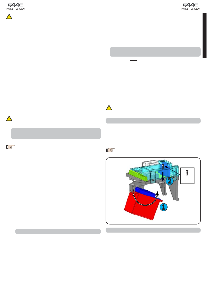
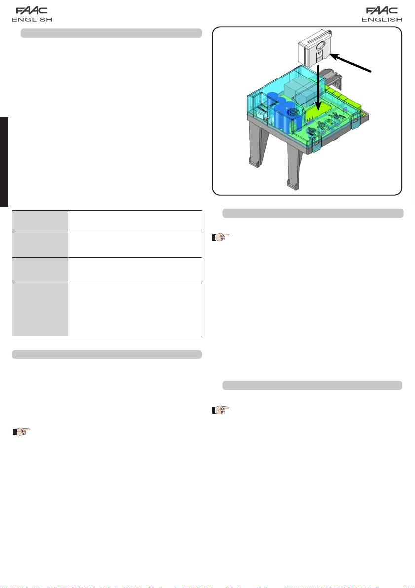
9 COLLEGAMENTO BATTERIE TAMPONE (OPTIONAL)
Il kit batterie tampone permette di azionare l’automazione
anche in assenza di alimentazione di rete. L’alloggiamento
delle batterie è previsto in apposito contenitore posto all’interno
dell’operatore (vedi sequenza in fig. 4).
Per l’installazione fare riferimento alle istruzioni specifiche.
Le batterie entrano in funzione quando viene
a mancare la tensione di rete.
3.9 x 16
2
1
Fig. 4
10 PROVA DELL’AUTOMAZIONE
Al termine della programmazione, controllare il corretto funzionamento dell’impianto. Verificare soprattutto il corretto
intervento dei dispositivi di sicurezza.
7
ITALIANO
Page 10

11 TABELLE DELLE LOGICHE
ITALIANO
pausa
ricarica il tempo
nessun effetto (1)
de dopo il tempo
apre le ante e richiu-
aprire
nessun effetto
(apertura inibita)
nessun effetto
nessun effetto
(apertura inibita)
tura inibita)
nessun effetto (aper-
ricarica il tempo
blocca e al disim-
pegno continua ad
nessun effetto
ricarica il tempo
immediatamente
inverte in chiusura
mento
blocca il funziona-
pausa
immediatamente
inverte in apertura
(chiusura inibita) (1)
pausa
pausa
blocca il funziona-
apertura
(chiusura inibita)
pegno inverte in
blocca e al disim-
(chiusura inibita)
immediatamente
inverte in apertura
nessun effetto
nessun effetto
mento
mento
blocca il funziona-
apre le ante
inibite)
nessun effetto
(apertura e chiusura
sura inibita)
nessun effetto (chiu-
tura inibita)
nessun effetto (aper-
inibite)
nessun effetto
(apertura e chiusura
FSW-OPEN
nessun effetto
nessun effetto
nessun effetto (aper-
apre le ante
nessun effetto (1)
aprire
(apertura inibita)
blocca e al disim-
pegno continua ad
nessun effetto
nessun effetto
(apertura inibita)
immediatamente
inverte in chiusura
mento
tura inibita)
blocca il funziona-
nessun effetto (1)
immediatamente
inverte in apertura
apertura
sura inibita)
nessun effetto (chiu-
sura inibita)
nessun effetto (chiu-
nessun effetto
sura inibita)
nessun effetto (chiu-
nessun effetto
pegno inverte in
blocca e al disim-
immediatamente
inverte in apertura
nessun effetto
mento
nessun effetto
blocca il funziona-
apre le ante
inibite)
(apertura e chiusura
sura inibita)
nessun effetto (chiu-
tura inibita)
nessun effetto (aper-
inibite)
(apertura e chiusura
In caso di utilizzo del comando OPEN B come contatto temporizzato, al
Tab. 5
LOGICA “A” (2) IMPULSI
STATO AUTOMAZIONE OPEN A OPEN B STOP FSW-OP FSW-CL FSW-OP/CL FSW-OPEN
pausa
de dopo il tempo
apre l’anta 1 e richiu-
pausa
de dopo il tempo
apre le ante e richiu-
CHIUSO
ricarica il tempo
ricarica il tempo
IN APERTURA nessun effetto (1) nessun effetto
di pausa
inverte in apertura
di pausa (1)
inverte in apertura
IN CHIUSURA
APERTO IN PAUSA
immediatamente
immediatamente
BLOCCATO chiude chiude
Tab. 6
LOGICA “EP” IMPULSI
STATO AUTOMAZIONE OPEN A OPEN B STOP FSW-OP FSW-CL FSW-OP/CL
8
mento
blocca il funziona-
mento (1)
blocca il funziona-
CHIUSO apre le ante apre l’anta 1
IN APERTURA
blocca il funziona-
blocca il funziona-
APERTO chiude chiude
mento
inverso
immediatamente (1)
Dopo STOP: Richiude l’anta/e
mento
Dopo OPEN: Riprende il moto in senso
BLOCCATO
IN CHIUSURA
presentarsi di un comando di OPEN A, la scheda effettuerà una apertura totale ed allo scadere del tempo di pausa richiuderà la sola anta 2.
scio causa la chiusura automatica del cancello allo scadere del tempo di pausa impostato.
(1) Se il ciclo è iniziato con un OPEN B (apertura parziale) un impulso di OPEN A aziona entrambe le ante in apertura.
(2) La logica automatica A è dotata della funzionalità “ Timer ”. Tale funzionalità permette di mantenere aperto il cancello con un comando di OPEN temporizzato il cui rila-
Page 11
INDEX
1 WARNINGS ....................................................................................................................2
2 LAYOUT AND CONNECTIONS .........................................................................................2
3 TECHNICAL SPECIFICATIONS ........................................................................................3
3.1 DESCRIPTION OF COMPONENTS ...........................................................................................3
3.2 DESCRIPTION OF TERMINAL-BOARDS .................................................................................... 3
3.3 ANTI-CRUSHING FUNCTION ...................................................................................................3
4 PROGRAMMING THE LOGIC ..........................................................................................3
5 PROGRAMMING THE SPEED ...........................................................................................3
6 START-UP ........................................................................................................................4
6.1 LEDS CHECK ........................................................................................................................4
6.2 PROGRAMMING THE DIPS-SWITCH ........................................................................................ 4
6.3 PRE-FLASHING ....................................................................................................................4
6.4 TIME - SETUP LEARNING .......................................................................................................4
6.4.1 AUTOMATIC SET-UP ........................................................................................................................ 4
6.4.2 MANUAL SET-UP ............................................................................................................................. 4
7 INSTALLATION OF BUS ACCESSORIES .............................................................................5
7.1 ADDRESSING THE BUS PHOTOCELLS .....................................................................................5
7.2 MEMORY STORAGE OF BUS ACCESSORIES..........................................................................6
8 MEMORY STORING THE RADIO CODE ............................................................................6
8.1 MEMORY STORAGE OF DS RADIO CONTROLS ......................................................................6
8.2 MEMORY STORAGE OF SLH RADIO CONTROLS ....................................................................6
8.3 MEMORY STORAGE OF LC RADIO CONTROLS (for some markets only) ............................. 7
8.3.1 REMOTE MEMORY STORAGE OF LC RADIO CONTROLS .................................................................7
8.4 RADIO CONTROLS DELETION PROCEDURE ........................................................................... 7
9 CONNECTION OF BUFFER BATTERIES (OPTIONAL) ...........................................................7
10 AUTOMATED SYSTEM TEST..............................................................................................7
11 LOGIC TABLES ...............................................................................................................8
ENGLISH
CE DECLARATION OF CONFORMITY
Manufacturer: FAAC S.p.A.
Address: Via Benini, 1 - 40069 Zola Predosa BOLOGNA - ITALY
Declares that: Control board model E391
conforms to the essential safety requirements of the following EEC directives
2006/95/EC Low Voltage directive
2004/108/EC Electromagnetic Compatibility directive
Additional information:
This product underwent a test in a typical, uniform configuration
(all products made by FAAC S.p.A)
Bologna, 01-07-2008
The Managing Director
A. Marcellan
WARNINGS
• Important! For the safety of people, it is important that all the instructions be carefully observed.
• Incorrect installation or incorrect use of the product could cause serious harm to people.
• Carefully read the instructions before beginning to install the product and keep them for future
reference.
• The symbol
of the automated system.
• The symbol
product.
indicates notes that are important for the safety of persons and for the good condition
draws your attention to the notes on the characteristics and operation of the
1
Page 12
CONTROL UNIT E391
1 WARNINGS
Before attempting any work on the control unit (connections, maintenance), always turn off power.
- Install, upstream of the system, a differential thermal breaker with adequate tripping threshold,
- Always separate power cables from control and safety cables (push-button, receiver, photocells, etc.).
- To avoid any electrical disturbance, use separate sheaths or a screened cable (with the screen earthed).
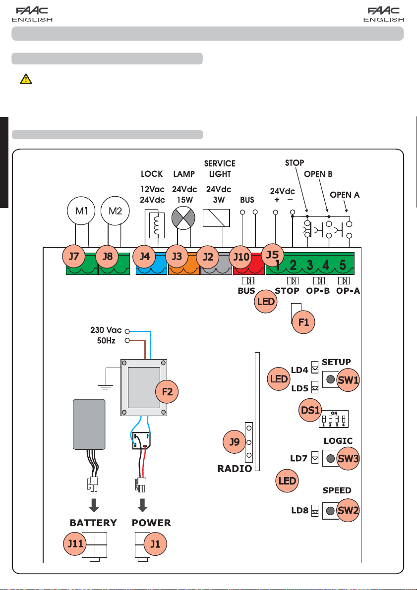
2 LAYOUT AND CONNECTIONS
(PARTIAL OPENING)
ENGLISH
(TOTAL OPENING)
Fig. 1
2
Page 13
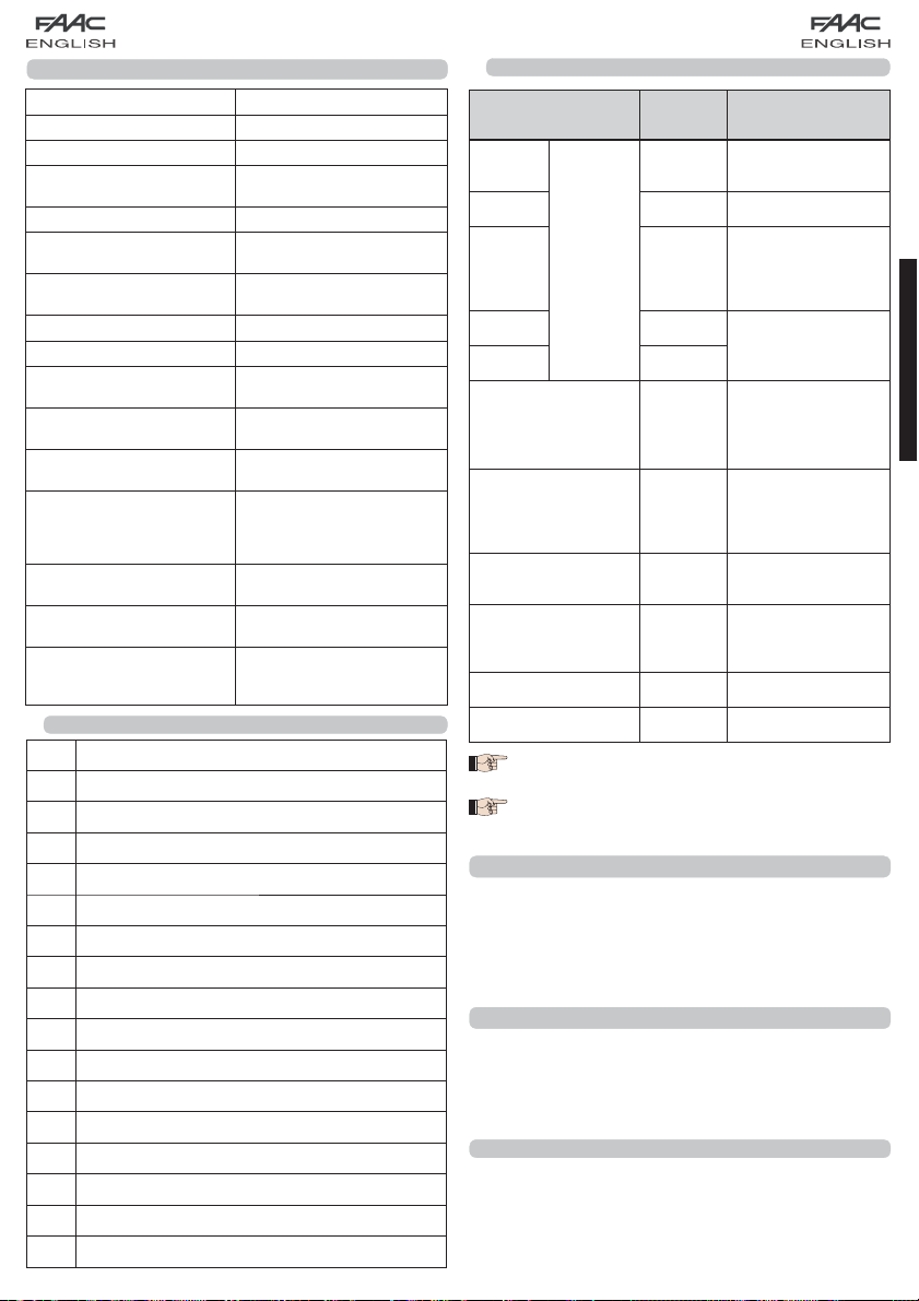
3 TECHNICAL SPECIFICATIONS
Power supply voltage
Absorbed power
Motor max. load
Accessories max. current
(+24V)
BUS Accessories max.current
Operating ambient temperature
Fuses
Function logics
Work time (time-out)
Pause time
Terminal board inputs
Connector inputs
Terminal board outputs
Programmable functions
Learning functions
Integrated radio channels
type
3.1 DESCRIPTION OF COMPONENTS
J1 POWER SUPPLY connector
J2
SERVICE LIGHT command terminal-board
J3 FLASHING LAMP terminal-board
J4 ELECTRIC LOCK terminal-board
J5 COMMANDS terminal-board
J7 MOTOR 1 terminal-board
J8 MOTOR 2 terminal-board
J9 Rapid connection for XF MODULE
J10 BUS terminal-board
J11 BATTERY connector
SW1 SET UP push-button
SW2 SPEED push-button
SW3 LOGIC push-button
DS1 Programming Dip-switch
F1 Accessories protective fuse
F2 Fuses protecting transformers and motors
LED Signalling LEDs
230Vac (+6% -10%) - 50Hz
-20°C - +55°C
F1 = self-resetting;
F2 = T2A-250V
1 minute (fixed)
Varies according to learning
(max. 10 min.)
Open A, Open B, Stop, BUS
Power supply, battery
module XF 433 or XF 868
Motors, flashing lamp, power
supply to accessories,
electric lock, service light
contact (90 sec fixed)
Logic (A, EP), Speed (high
13°/sec and low 10°/sec)
Pause time, leaf 2 delay at
DS, SLH (max 250 channels)
LC (max 250 channels - FOR
SOME MARKETS ONLY)
10W
150W x 2
250 mA
400 mA
EP, A
(I/O)
closing
3.2 DESCRIPTION OF TERMINAL-BOARDS
Terminal and/or
terminal-board
1
Description Device connected
+24V
Power supply for
accessories
2 GND Negative
3 STOP
J5
4 OPEN B
5 OPEN A
J10
RED terminal
J2
GREY terminal
J3
ORANGE terminal
J4
BLUE terminal
SERVICE
LIGHT
LAMP
LOCK
Device with NC
contact which causes
the automated
system to shut down
Device with N.O
contact (see chap.
FUNCTION LOGICS)
Safety devices with
BUS
BUS technology
Service Light control
output (connect a
relay coil at 24Vdc100mA max)
Flashing lamp 24Vdc
- 15W
Electric lock 12Vac or
24 Vdc (to be installed
on leaf 1)
J7 MOT1 Motor 1 (leaf 1)
J8 MOT2 Motor 2 (leaf 2)
Leaf 1 means the leaf which opens first during
the opening operation.
The service light control is active during the
entire gate opening or closing movement and
for the successive 90 seconds.
3.3 ANTI-CRUSHING FUNCTION
If the gate detects an obstacle during the opening or closing
movement, the anti-crushing function activates and reverses
the sense of direction of the operator, thus increasing the safety
degree of the automated system.
The sensitivity of the anti-crushing device can be adjusted with
the dip-switch no.3 (see par.6.2).
4 PROGRAMMING THE LOGIC
The function logic can be selected at any time by pressing
push-button SW3.
The selected logic is then displayed on LED LD7:
LED on = AUTOMATIC logic (A)
LED off = SEMIAUTOMATIC STEPPED logic (EP)
5 PROGRAMMING THE SPEED
The function logic can be adjusted at any time by pressing
push-button SW2.
The selected logic is then displayed on LED LD8:
LED on = HIGH speed (13 °/sec)
LED off = LOW speed (10 °/sec)
3
ENGLISH
Page 14
6 START-UP
6.1 LEDS CHECK
The following table shows that status of the LEDs in relation to
the status of the inputs (the closed at rest automated system
condition is shown in bold).
Check the status of the signalling LEDs as per table below:
Tab.1 – Operation of inputs status LEDs
LED ON (closed contact) OFF (open contact)
STOP Command disabled Command enabled
OPEN A Command enabled Command disabled
OPEN B Command enabled Command disabled
BUS
ENGLISH
6.2 PROGRAMMING THE DIPS-SWITCH
The following tables show the settings of the DS1 dip-switch for
programming force, pre-flashing and reversing stroke.
Tab. 2 - DS1 programming (default settings in bold)
DS1 DS2 DS3 DS4 Description
ON ON HIGH FORCE
ON OFF MEDIUM - HIGH FORCE
OFF ON MEDIUM - LOW FORCE
OFF OFF LOW FORCE
ON ANTI-WIND ON
OFF ANTI-WIND OFF
If you connect an electric lock to terminal J4,
position DS4 to ON to enable the reversing stroke (before opening, the motors thrust to close,
thus facilitating the electric lock to uncouple).
By setting dip-switch DS3 on ON, a specialBy setting dip-switch DS3 on ON, a special
windproof function is activated that enables the
gate operation even if strong wind is present.
6.3 PRE-FLASHING
The pre-flashing function can be activated and disabled (following an OPEN command, the unit activates the flashing lamp
for 3 seconds before it starts the movement). Procedure:
Press LOGIC key (SW3) for at least 5 secs. to ACTIVATE
1.
pre-flashing.
Press SPEED key (SW2) for at least 5 secs. to DESACTIVATE
2.
pre-flashing.
In both cases check if the LED of the pressed key
changes its status: in such cases it means that
the function of the key and not the pre-flashing
was changed.
See par. 7.2
ON REVERSING STROKE ON
OFF REVERSING STROKE OFF
6.4 TIME - SETUP LEARNING
Before any manoeuvre is executed, a SETUP
cycle must first be run.
During SETUP do not interrupt the photocells
because their interruption causes the immediate stop of the leaves. To end the procedure,
repeat SETUP from the beginning.
When the board is powered up and a SETUP cycle has never
been executed, LEDs LD4 and LD5 begin to flash slowly to signal
that a SETUP cycle must be executed.
There are two possible types of SETUP: AUTOMATIC and
MANUAL
6.4.1 AUTOMATIC SET-UP
To execute an AUTOMATIC SETUP, follow the procedure below:
Take the leaves to mid-point.
1.
Hold down the SETUP (SW1) push-button until the 2 adjacent
2.
LEDs (LD4 and LD5) light up on steady beam.
Release the SETUP push-button, LEDs LD4 and LD5 begin
3.
to flash rapidly.
Leaf 2 (if present) starts the closing movement, stopping
4.
when it reaches the closing mechanical stop.
Leaf 1 starts the closing movement, stopping when it
5.
reaches the closing mechanical stop.
Leaf 1 starts the opening movement.
6.
Leaf 2 (if present) starts the opening movement after a
7.
fixed delay at opening.
Leaves 1 and 2 (if present) stop when they reach the
8.
opening mechanical stop.
Wait for LEDs LD4 and LD5 to go OFF, which means that the
9.
SETUP procedure has finished.
Give an OPEN pulse to close the gate.
10.
When the SETUP procedure has been started,
if the leaves at point 4 and 5 open instead of
closing, the motor power supply cables must
be changed over.
When using the AUTOMATIC SETUP, the slow
down spaces, the leaf opening and closing
delays, and the pause time (30 sec., with A
logic), are all preset by the board and cannot
be modified.
6.4.2 MANUAL SET-UP
To execute a MANUAL SETUP, follow the procedure below:
Take the leaves to mid-point.
1.
Hold down the SETUP (SW1) push-button until the leaves
2.
start to move.
Release the SETUP push-button, LEDs LD4 and LD5 begin
3.
to flash rapidly
Leaf 2 (if present) starts the closing movement, stopping
4.
when it reaches the closing mechanical stop
Leaf 1 starts the closing movement, stopping when it rea-
5.
ches the closing mechanical stop
Leaf 1 starts the opening movement.
6.
Leaf 2 (if present) starts the opening movement after a
7.
fixed delay at opening.
Leaves 1 and 2 (if present) stop when they reach the ope-
8.
ning mechanical stop.
If LOW force was set, wait for about 5 sec checking if the
9.
flashing lamp goes OFF.
4
Page 15
10.
If the A Logic was selected, the board begins to count the
pause time (max 10 min) and, after the required time has
elapsed, give an OPENING pulse to continue the procedure. Otherwise, if you have selected the EP logic, the leafs
close immediatly as shown in next point.
11.
Leaf 2 (if present) starts the closing movement an the board
begins to count the delay of the leaf at closing.
12.
After the required time has elapsed, give an OPEN pulse
to make leaf 1 start the closing movement.
13.
Leaves 1 and 2 (if present) stop when they reach the closing
mechanical stop.
14.
Wait for LEDs LD4 and LD5 to go OFF, which means that the
SETUP procedure has finished.
When the SETUP procedure has been started,
if the leaves at point 4 and 5 open instead of
closing, the motor power supply cables must
be changed over.
When using the MANUAL SETUP, the slow-down
spaces, and leaf delays at opening are preset
by the board and cannot be modified. However,
delay at leaf closing and pause time can be
programmed during learning.
7 INSTALLATION OF BUS ACCESSORIES
This board is supplied with a BUS circuit enabling easy connection of a high number of BUS accessories (e.g. up to 16
photocells pairs), appropriately programmed, using only two
cable without polarity.
Below we describe the addressing and memory storage of
the BUS photocells.
For other future accessories, refer to the specific instructions.
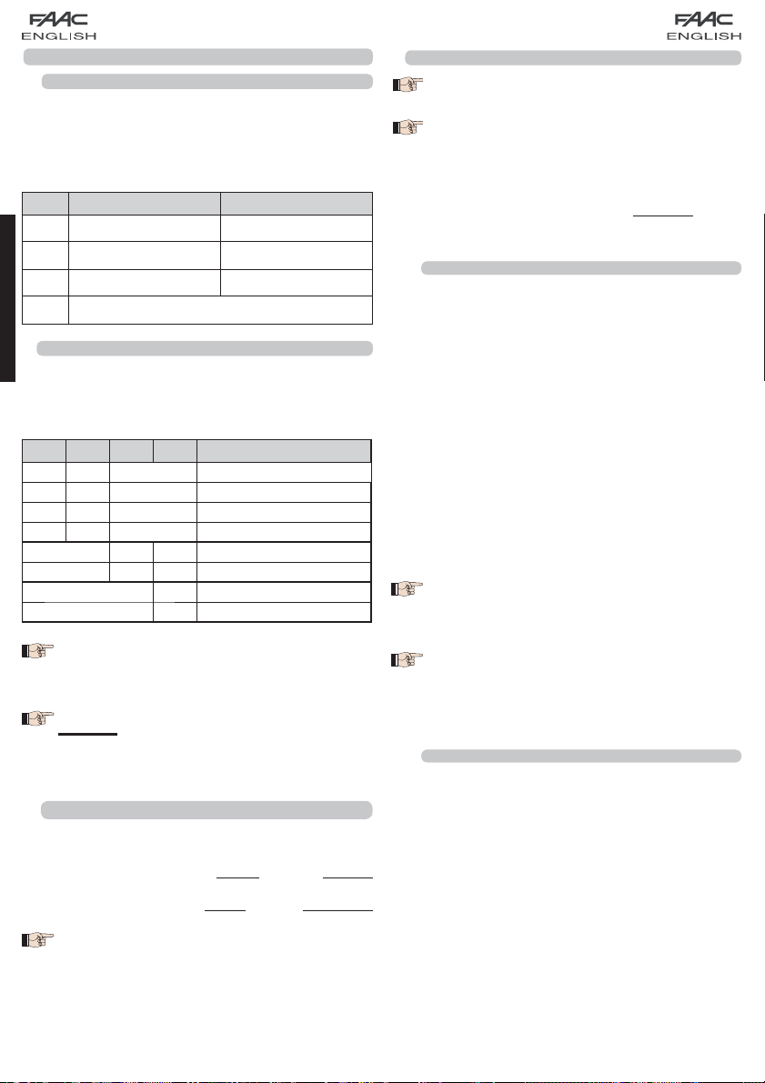
7.1 ADDRESSING THE BUS PHOTOCELLS
Important: the same address must be given to
both transmitter and receiver.
Make sure that there are no two or more
photocells pairs with the same address.
If no BUS accessory is used, leave the BUS con-
nector free (J10 - fig. 1).
A maximum of 16 BUS photocell pairs can be connected to
the board.
The photocells are split into groups:
Opening photocells: max 6
Closing photocells: max 7
Opening /Closing photocells: max 2
Photocell used as an OPEN pulse: max 1
Fig. 2
Fig. 2 shows a 2-swing leaf automated system indicating the
coverage beams of the photocells:
A: Photocells with OPENING and CLOSING action.
B: Photocells with OPENING action
C: Photocells with OPENING action
D: Photocells with CLOSING action
Table 3 shows the programming operations of the dip-switch
inside the transmitter and of the BUS Photocells receiver.
Tab. 3 - Addressing of BUS Photocells
Dip1 Dip2 Dip3 Dip4 Ref. Type
OFF OFF OFF OFF
OFF OFF OFF ON
OFF OFF ON OFF
OFF OFF ON ON
OFF ON ON OFF
OFF ON ON ON
ON OFF OFF OFF
ON OFF OFF ON
ON OFF ON OFF
ON OFF ON ON
ON ON OFF OFF
ON ON OFF ON
ON ON ON OFF
OFF ON OFF OFF
OFF ON OFF ON
ON ON ON ON / OPEN PULSE
B -C OPENING
D CLOSING
A
OPENING and
CLOSING
ENGLISH
5
Page 16
7.2 MEMORY STORAGE OF BUS ACCESSORIES
You can add the BUS photocells to the system at any time,
simply by memory-storing them on the board, observing the
following procedure:
Install and program the accessories using the required
1.
address (see paragraph 7.1)
Cut power to the board.
2.
Connect the two accessories cables to the red terminal-
3.
board J10 (any polarity will do).
Power up the board, taking care to first connect the
4.
main power supply (transformer output) and then any
batteries.
Quickly press once only the SW1 (SETUP) push-button, to
5.
execute learning. The BUS LED flashes.
Give an OPEN A impulse, leaves will move and the BUS
6.
learning procedure is over.
The board has memory stored the BUS accessories. Follow the
ENGLISH
instructions in the table below to check if the BUS connection
is correct.
Tab. 4 - Description of BUS LED
Steady light
Slow flashing
lamp
(flash
every 0.5 sec)
Light OFF
(flash every 2.5
sec)
Fast flashing
lamp
(flash
every 0.2 sec)
Normal operation (LED ON even in the
absence of photocells)
At least one input engaged: photocell
engaged or not aligned, Open A or Open
B or Stop input engaged
BUS line short circuited
If you have detected a BUS connection
error, repeat the acquisition procedure. If
the error is repeated, make sure that there
is not more than one accessory with the
same address in the system (also see the
accessories instructions)
8 MEMORY STORING THE RADIO CODE
The control board has an integrated 2-channel decoding
system (DS, SLH, LC) named OMNIDEC. This system makes it
possible to memory-store both total opening (OPEN A) and
partial opening OPEN B) of the automated system - this is made
possible by an additional receiver module (fig.3 ref. /) and
radio controls on the same frequency.
The 3 types of radio codes (DS, LSH, LC) cannot
coexist.
Only one radio code can be used at a time.
To change over from one code to another, you
must delete the existing one (see paragraph
on deletion), and repeat the memory-storage
procedure.
8.1 MEMORY STORAGE OF DS RADIO CONTROLS
A maximum of two codes can be stored. One
on the OPEN A channel and one on the OPEN B
channel.
On the DS radio control, select the required ON-OFF
1.
combination for the 12 dip-switches.
Press the LOGIC (SW3) or SPEED (SW2) push-button, to
2.
memory store respectively total opening (OPEN A) or partial
opening (OPEN B), and as you hold it down, also press the
SETUP (SW1) push-button. The relevant LED starts to flash
slowly for 5 sec..
Release both push-buttons.
3.
Within these 5 sec., press the appropriate push-button on
4.
the radio control.
The relevant LED lights up on steady beam for 1 second and
5.
then goes OFF, indicating that storage was executed.
To add other radio controls, set the same ON - OFF
6.
combination used in point 1.
8.2 MEMORY STORAGE OF SLH RADIO CONTROLS
A maximum of 250 codes can be memory
stored, split between OPEN A and OPEN B.
On the SLH radio control, simultaneously press and hold
1.
down push-buttons P1 and P2.
The radio control LED begins to flash.
2.
Release both push-buttons.
3.
Press the LOGIC (SW3) or SPEED (SW2) push-button, to
4.
memory store respectively total opening (OPEN A) or partial
opening (OPEN B), and as you hold it down, also press the
SETUP (SW1) push-button. The relevant LED starts to flash
slowly for 5 sec.
Release both push-buttons.
5.
Within these 5 sec., while the radio control LED is still flashing,
6.
press and hold down the required push-button on the radio
control (the radio control LED lights up on steady beam).
The LED on the board lights up on steady beam for 1
7.
second and then goes OFF, indicating that storage was
executed.
Release the radio control push-button.
8.
6
/
Fig. 3
Page 17

9.
Quickly press twice the memory stored radio control pushbutton.
The automated system performs one opening
operation. Make sure that the automated
system is free of any obstacle created by
persons or things.
To add other radio controls, transfer the code of the memorystored push-button of the radio control to the relevant pushbutton of the radio controls to be added, observing the
following procedure.
•
On the memory stored radio control, simultaneously press
and hold down push-buttons P1 and P2.
•
The radio control LED begins to flash.
•
Release both push-buttons.
•
Press the memory stored push-button and hold it down
(the radio control LED lights up on steady beam).
•
Bring the radio controls near, press and hold down the
push-button of the radio control to be added, releasing
it only after the double flash of the radio control LED,
which indicates memory storage executed.
•
Quickly press twice the push-button of the memory stored
radio control.
The automated system performs one opening
operation. Make sure that the automated
system is free of any obstacle created by
persons or things.
8.3 MEMORY STORAGE OF LC RADIO CONTROLS
(for some markets only)
A maximum of 250 codes can be memory
stored, split between OPEN A and OPEN B.
Within 5 sec. press the push-button of the radio control
3.
that had been memory stored to enable learning on the
selected channel.
The LED on the board relating to the channel being learned
4.
flashes for 5 sec., within which time the code of another
radio control must be transmitted.
The LED lights up on steady beam for 2 seconds, indicating
5.
memory storage executed, and then resumes flashing for
5 sec., during which other radio controls can be memory
stored, and then goes OFF.
8.4 RADIO CONTROLS DELETION PROCEDURE
1.
To delete ALL the input radio control codes, press pushbutton LOGIC (SW3) or SPEED (SW2) and, while holding it
down, also press push-button SETUP (SW1) for 10 sec.
2.
The LED relating to the pressed push-button flashes for
the first 5 sec, and then flashes more quickly for the next
5 sec.
3.
Both LEDs light up on steady beam for 2 sec and then go
OFF (deletion completed).(deletion completed).deletion completed). completed).completed).).
4.
Release both push-buttons.
This operation is NOT reversible. All codes of
radio controls stored as OPEN A and OPEN B will
be deleted.
9 CONNECTION OF BUFFER BATTERIES (OPTIONAL)
The buffer battery kit will activate the automated system
in the event of a power cut. The batteries are housed in
an appropriate container located inside the operator (see
sequence in fig.4).
To install, consult the specific instructions.
The batteries come into operation when a
power cut occurs.
ENGLISH
1.
Use LC remote controls only with receiver module at 433
MHz.
2.
Press the LOGIC (SW3) or SPEED (SW2) push-button, to
memory store respectively total opening (OPEN A) or partial
opening (OPEN B), and as you hold it down, also press the
SETUP (SW1) push-button. The relevant LED starts to flash
slowly for 5 sec.
3.
Release both push-buttons. Within these 5 sec., press the
appropriate push-button on the LC remote control.
4.
The LED lights up on steady beam for 1 second, indicating
memory storage executed, and then resumes flashing for
another 5 sec., during which another radio control (point
4) can be memory stored.
5.
When the 5 sec. have elapsed, the LED goes OFF indicating
the end of the procedure.
6.
To add other radio controls, repeat the operation at point 1.
8.3.1 REMOTE MEMORY STORAGE OF LC RADIO CONTROLS
Other radio controls can be remotely stored only with the LC
radio controls, i.e. without using the LOGIC-SPEED-SETUP push-LOGIC-SPEED-SETUP push- pushbuttons, but using a previously stored radio control.
Get a radio control already stored on one of the 2 channels
1.
(OPEN A or OPEN B ).
Press and hold down push-buttons P1 and P2 simultaneously
2.
until both the LEDs flash slowly for 5 sec.
3.9 x 16
2
1
Fig. 4
10 AUTOMATED SYSTEM TEST
When you have finished programming, check if the system is
operating correctly. In particular, check if the safety devices
are operating correctly.
7
Page 18

11 LOGIC TABLES
ENGLISH
time
FSW-OPEN
opens leaves and
closes after pause
inhibited)
no effect (opening
no effect
inhibited)
no effect (opening
inhibited)
no effect (opening
time
no effect (1)
recharges pause
(closing inhibited) (1)
reverses immediately
time
to open at
disengagement
stops and continues
no effect
at closing
reverses immediately
stops and, at
recharges pause
(closing inhibited)
time
recharges pause
(closing inhibited)
reverses immediately
stops operation no effect
at opening
opens leaves
disengagement,
no effect (opening
reverses at opening
and closing inhibited)
inhibited)
at opening
no effect (closing
inhibited)
no effect (opening
stops operation no effect
no effect (opening
and closing inhibited)
no effect (1)
opens leaves
inhibited)
to open at
disengagement
no effect (opening
no effect
inhibited)
no effect (opening
inhibited)
no effect (opening
no effect (closing
stops and continues
no effect
no effect (closing
at closing
reverses immediately
no effect (closing
at opening
no effect (1)
reverses immediately
inhibited)
stops and, at
disengagement,
reverses at opening
inhibited)
at opening
reverses immediately
no effect
inhibited)
opens leaves
no effect (opening
and closing inhibited)
inhibited)
no effect (closing
inhibited)
no effect (opening
no effect (opening
and closing inhibited)
Tab. 5
LOGIC “A” (2) PULSES
STATUS OF AUTOMATED
OPEN A OPEN B STOP FSW-OP FSW-CL FSW-OP/CL
SYSTEM
time
opens leaf 1 and
closes after pause
time
opens leaves and
closes after pause
CLOSED
OPENING no effect (1) no effect stops operation
recharge
recharge
at opening
the pause time
reverses immediately
at opening
the pause time (1)
reverses immediately
CLOSING
OPEN IN PAUSE
STOPPED closes closes
Tab. 6
LOGIC “EP” PULSES
STATUS OF AUTOMATED
8
OPEN A OPEN B STOP FSW-OP FSW-CL FSW-OP/CL FSW-OPEN
SYSTEM
opens leaves opens leaf 1
CLOSED
OPENING stops operation (1) stops operation stops operation
OPEN closes closes
direction
immediately (1)
After STOP: Re-closes the leaf/ves
After OPEN: Restarts moving in reverse
STOPPED
CLOSING stops operation stops operation stops operation no effect
mand, the gate is automatically closed at the end of the set pause time. If the OPEN B command is used as a timed contact, when an OPEN A command is sent, the
board performs a total opening and at the end of the pause time it closes only leaf 2.
(1) If the cycle began with OPEN-B (partial opening), an OPEN-A pulse will activate both leaves to open.
(2) The automatic logic A is equipped with the “Timer” function. This function makes it possible to keep the gate open with a timed OPEN command. On release of this com-
Page 19

Ç
INDEX
1 AVERTISSEMENTS ...........................................................................................................2
2 LAYOUT ET CONNEXIONS ..............................................................................................2
3 CARACTÉRISTIQUES TECHNIQUES .................................................................................3
3.1 DESCRIPTION DES COMPOSANTS .........................................................................................3
3.2 DESCRIPTION DES BORNIERS ................................................................................................3
3.3 FONCTION ANTI-ÉCRASEMENT ............................................................................................. 3
4 PROGRAMMATION DE LA LOGIQUE ...............................................................................3
5 PROGRAMMATION DE LA VITESSE ..................................................................................3
6 MISE EN FONCTION .......................................................................................................4
6.1 VÉRIFICATION DES LEDS ........................................................................................................4
6.2 PROGRAMMATION DES DIP-SWITCHES .................................................................................. 4
6.3 PRÉ-CLIGNOTEMENT ............................................................................................................. 4
6.4 APPRENTISSAGE TEMPS - SETUP ............................................................................................ 4
6.4.1 SETUP AUTOMATIQUE .....................................................................................................................4
6.4.2 SETUP MANUEL .............................................................................................................................. 4
7 INSTALLATION DES ACCESSOIRES BUS ...........................................................................5
7.1 ADRESSAGE DES PHOTOCELLULES BUS ................................................................................. 5
7.2 MÉMORISATION DES ACCESSOIRES BUS ............................................................................... 6
8 MÉMORISATION DE LA CODIFICATION RADIO ...............................................................6
8.1 MÉMORISATION DES RADIOCOMMANDES DS ....................................................................... 6
8.2 MÉMORISATION DES RADIOCOMMANDES SLH ..................................................................... 6
8.3 MÉMORISATION DES RADIOCOMMANDES LC (uniquement pour certains marchés) ......... 7
8.3.1 MÉMORISATION À DISTANCE DES RADIOCOMMANDES LC ............................................................ 7
8.4 PROCÉDURE D’EFFACEMENT DES RADIOCOMMANDES ......................................................... 7
9 CONNEXION DES BATTERIES TAMPON (OPTION) ............................................................7
10 ESSAI DE L’AUTOMATISME ..............................................................................................7
11 TABLEAUX DES LOGIQUES ..............................................................................................8
AIS
FRAN
DÉCLARATION CE DE CONFORMITÉÉ
Fabricant: FAAC S.p.A.
Adresse: Via Benini, 1 - 40069 Zola Predosa BOLOGNA - ITALIE
Déclare que: La platine électronique mod. E391
est construit pour être incorporé dans une machine ou pour être assemblé à d’autres appareillages, afin de constituer une machine
conforme aux termes de la Directive 2006/42/CE
est conforme aux exigences essentielles de sécurité des directives CEE suivantes
2006/95/CE Directive Basse Tension
2004/108/CE Directive Compatibilité Électromagnétique
Note complémentaire:
Ce produit a été testé dans une configuration typique homogène
(tous les produits sont fabriqués par FAAC S.p.A.)
Bologna, le 01-07-2008 L’Administrateur Délégué
A. Marcellan
AVERTISSEMENTS
• Attention! Il est important pour la sécurité des personnes de suivre attentivement toute l’instruction.
• Une installation ou un usage erronés du produit peut provoquer de sérieuses blessures aux personnes.
• Lire attentivement les instructions avant de commencer l’installation du produit et les conserver pour toute référence
future.
• Le symbole
l’automatisme.
• Le symbole
produit.
souligne des remarques importantes pour la sécurité des personnes et le parfait état de
attire l’attention sur des remarques concernant les caractéristiques ou le fonctionnement du
1
Page 20

ARMOIRE ÉLECTRONIQUE E391
1 AVERTISSEMENTS
Avant tout type d’intervention sur l’armoire électronique (connexions, entretien), toujours couper le courant
électrique.
- Prévoir en amont de l’installation un disjoncteur magnétothermique différentiel au seuil d’intervention adéquat.
- Toujours séparer les câbles d’alimentation des câbles de commande et de sécurité (bouton-poussoir, récepteur,
photocellules, etc.).
- Pour éviter toute perturbation électrique, utiliser des gaines séparées ou un câble blindé (blindage connecté à la masse).
2 LAYOUT ET CONNEXIONS
(OUVERTURE PARTIELLE)
(OUVERTURE TOTALE)
FRANÇAIS
Fig. 1
2
Page 21

Ç
3 CARACTÉRISTIQUES TECHNIQUES
Tension d’alimentation
Puissance absorbée
Charge maxi Moteurs
Courant maxi accessoires
(+24V)
Courant maxi accessoires
BUS
Température de
fonctionnement
Fusibles de protection
Logiques de
fonctionnement
Temps de fonctionnement
(délai d’attente)
Temps de pause
Entrées bornier
Entrées connecteur
Sorties bornier
Fonctions programmables
Fonctions apprentissage
Types de canaux radio
intégrés
3.1 DESCRIPTION DES COMPOSANTS
J1 Connecteur ALIMENTATION
J2
Bornier commande LUMIÈRE DE SERVICE
J3 Bornier LAMPE CLIGNOTANTE
J4 Bornier ÉLECTROSERRURE
J5 Bornier COMMANDES
J7 Bornier MOTEUR 1
J8 Bornier MOTEUR 2
J9 Embrochage rapide MODULE XF
J10 Bornier BUS
J11 Connecteur BATTERIE
SW1 Bouton-poussoir SETUP
SW2 Bouton-poussoir SPEED
SW3 Bouton-poussoir LOGIC
DS1 Dip-switche programmation
F1 Fusible protection accessoires
F2 Fusible protection transformateur et moteurs
LED LEDs de signalisation
230Vca (+6% -10%) - 50Hz
10W
150W x 2
250 mA
400 mA
-20°C +55°C
F1 = autorégénérateur; F2 = T2A-250V
EP, A
1 minute (fixe)
Variable en fonction de l’apprentissage
(10 min. maxi)
Open A, Open B, Stop, BUS (E/S)
Alimentation, batterie,
module XF433 ou XF868
Moteurs, lampe clignotante, alimentation
accessoires, électroserrure, contact
lumière de service (90 s fixe)
Logique (A, EP), Vitesse (haute 13e/s et
Temps de pause, retard de vantail 2 en
LC (maxi 250 canaux – UNIQUEMENT
basse 10e/s)
fermeture
DS, SLH (maxi 250 canaux)
POUR CERTAINS MARCHÉS)
3.2 DESCRIPTION DES BORNIERS
Borne et/ou Bornier Description Dispositif connecté
1
2 GND Négatif
3 STOP
4 OPEN B Dispositif avec contact
5 OPEN A
Borne ROUGE
Borne GRISE
Borne ORANGE
Borne BLEU CLAIR
J5
J10
J2
J3
J4
J7 MOT1 Moteur 1 (vantail 1)
J8 MOT2 Moteur 2 (vantail 2)
+24V Alimentation accessoires
Dispositif avec contact
N.F. qui provoque
le blocage de
l’automatisme
N.O. (voir chap. LOGIQUES
DE FONCTIONNEMENT)
Dispositifs de sécurité
BUS
avec technologie BUS
Sortie commande Lumière
SERVICE
LIGHT
LAMP
LOCK
de service (connecter une
bobine relay à 24Vcc100mA maxi)
Lampe clignotante
24Vcc - 15W
Électroserrure
12Vca ou 24Vcc (à installer
sur vantail 1)
On entend par vantail 1 le vantail qui s’ouvre le
premier en ouverture.
La commande lumière de service est active
durant toute l’actionnement en ouverture ou en
fermeture du portail et durant les 90 secondes
suivantes.
3.3 FONCTION ANTI-ÉCRASEMENT
Si le portail rencontre un obstacle durant le mouvement d’ouverture ou de fermeture, la fonction anti-écrasement s’active
en inversant le sens de marche de l’opérateur, augmentant
ainsi le degré de sécurité de l’automatisme.
On peut régler la sensibilité de l’anti-écrasement au moyen du
DIP-SWITCHE n°3 (voir par.6.2).
4 PROGRAMMATION DE LA LOGIQUE
La logique de fonctionnement peut être sélectionnée à tout
moment en appuyant sur le bouton-poussoir SW3.
La logique sélectionnée est ensuite affichée par la LED LD7:
LED allumée = logique AUTOMATIQUE (A)
LED éteinte = logique SEMI-AUTOMATIQUE PAS À PAS (EP)
5 PROGRAMMATION DE LA VITESSE
La vitesse de fonctionnement peut être réglée à tout moment
en appuyant sur le bouton-poussoir SW2.
La logique sélectionnée est ensuite affichée par la LED LD8:
LED allumée = GRANDE vitesse (13e/s)
LED éteinte = FAIBLE vitesse (10e/s)
3
AIS
FRAN
Page 22

6 MISE EN FONCTION
6.1 VÉRIFICATION DES LEDS
Le tableau ci-après indique l’état des LEDs en fonction de l’état
des entrées (en caractères gras la condition d’automatisme
fermée au repos).
Vérifier l’état des LEDs de signalisation d’après le tableau suivant.
Tabl. 1 - Fonctionnement des LEDs de signalisation de l’état
des entrées
LED ALLUMÉE (contact fermé) ÉTEINTE (contact ouvert)
STOP Commande inactive Commande active
OPEN A Commande active Commande inactive
OPEN B Commande active Commande inactive
BUS
6.2 PROGRAMMATION DES DIP-SWITCHES
Le tableau suivant indique la programmation du dip-switche
DS1 pour la programmation de la force, du préclignotement et
du coup d’inversion.
Tabl. 2 - Programmation DS1 (en caractères gras on indique
les sélections par défaut)
DS1 DS2 DS3 DS4 Description
ON ON FORCE HAUTE
ON OFF FORCE MOYENNE HAUTE
FRANÇAIS
OFF ON FORCE MOYENNE BASSE
OFF OFF FORCE BASSE
ON ANTI-VENT ON
OFF ANTI-VENT OFF
Si l’on connecte une électroserrure à la borne
J4, positionner le DIP-SWITCHE DS4 sur ON pour
valider le coup d’inversion (avant l’ouverture,
les moteurs poussent en fermeture, facilitant le
déclenchement de l’électroserrure).
En sélectionnant sur ON, le dip-switche DS3
active une fonction spéciale anti-vent qui permet au portail de fonctionner également en
présence de rafales de vent.
6.3 PRÉ-CLIGNOTEMENT
On peut activer et désactiver la fonction de pré-clignotement
(à la suite d’une commande d’OPEN, l’appareillage active la
lampe clignotante pendant 3 secondes avant de commencer
le mouvement), en agissant comme suit:
Appuyer pendant 5 s au moins sur la touche LOGIC
1.
(SW3) pour ACTIVER le préclignotement.
Appuyer pendant 5 sec au moins sur la touche SPEED
2.
(SW2) pour DESACTIVER le préclignotement.
Dans les deux cas, vérifier que la LED correspondant à la touche enfoncée ne change
pas d’état, cela signifierait qu’on a modifié la
fonction relative à la touche et non le préclignotement.
Voir par. 7.2
ON COUP D’INVERSION ON
OFF COUP D’INVERSION OFF
6.4 APPRENTISSAGE TEMPS - SETUP
Avant toute manœuvre, exécuter un cycle de
SETUP
Durant la procédure de SETUP ne pas inter-
rompre les photocellules, car leur interruption
provoque l’arrêt immédiat des vantaux. Pour
terminer la procédure, répéter le SETUP depuis
le début.
Quand on met la platine sous tension et qu’on n’a jamais
exécuté aucun cycle de SETUP, les LEDs LD4 et LD5 commencent
à clignoter lentement pour signaler la nécessité d’exécuter un
cycle de SETUP.
Deux types de SETUP sont disponibles: AUTOMATIQUE et
MANUEL
6.4.1 SETUP AUTOMATIQUE
Pour exécuter le SETUP AUTOMATIQUE, procéder comme suit:
1.
Amener les vantaux à mi-ouverture.
2.
Maintenir le bouton-poussoir SETUP (SW1) enfoncé jusqu’à ce
que les 2 LEDs adjacentes (LD4 et LD5) s’allument fixes.
3.
Relâcher le bouton-poussoir SETUP, les LEDs LD4 et LD5
commencent à clignoter rapidement.
4.
Le vantail 2 (si présent) commence le mouvement de
fermeture en s’arrêtant sur la butée mécanique de
fermeture.
5.
Le vantail 1 commence le mouvement de fermeture en
s’arrêtant sur la butée mécanique de fermeture.
6.
Le vantail 1 commence le mouvement d’ouverture.
7.
Le vantail 2 (si présent) commence le mouvement
d’ouverture après un retard fixe en ouverture.
8.
Les vantaux 1 et 2 (si présent) s’arrêtent sur la butée
mécanique d’ouverture.
9.
Attendre que les LEDs LD4 et LD5 s’éteignent indiquant que
la procédure de SETUP est terminée.
10.
Donner une impulsion d’OPEN pour fermer le portail.
Une fois que la procédure de SETUP est lancée,
si les vantaux au point 4 et 5 s’ouvrent au lieu
de se fermer, inverser les câbles d’alimentation
des moteurs.
Avec le SETUP AUTOMATIQUE, les espaces
de ralentissement, les retards de vantail en
ouverture et fermeture et le temps pause (30s,
avec logique A) sont présélectionnés par la
platine et on ne peut pas les modifier.
6.4.2 SETUP MANUEL
Pour exécuter le SETUP MANUEL, procéder comme suit:
1.
Amener les vantaux à mi-ouverture.
2.
Maintenir le bouton-poussoir SETUP (SW1) enfoncé jusqu’à ce
que les vantaux commencent à s’actionner.
3.
Relâcher le bouton-poussoir SETUP, les LEDs LD4 et LD5
commencent à clignoter rapidement.
4.
Le vantail 2 (si présent) commence le mouvement de
fermeture en s’arrêtant sur la butée mécanique de
fermeture.
5.
Le vantail 1 commence le mouvement de fermeture en
s’arrêtant sur la butée mécanique de fermeture.
6.
Le vantail 1 commence le mouvement d’ouverture.
7.
Le vantail 2 (si présent) commence le mouvement
d’ouverture après un retard fixe en ouverture.
8.
Les vantaux 1 et 2 (si présent) s’arrêtent sur la butée
mécanique d’ouverture.
4
Page 23

Ç
Si l’on a programmé la force BASSE, attendre environ 5 s en
9.
vérifiant l’extinction de la lampe clignotante.
Si l’on a sélectionné la logique A, la platine commence
10.
le comptage du temps de pause (10 min. maxi) et, après
le temps souhaité, donner une impulsion d’OPEN pour
continuer la procédure. Autrement, si vous avez choisi la
logique d’EP, les vanteaux ferment immédiatement selon
le point prochain.
Le vantail 2 (si présent) commence le mouvement de
11.
fermeture et la platine commence le comptage du retard
de vantail en fermeture.
Lorsque le retard souhaité s’est écoulé, donner une impulsion
12.
d’OPEN pour que le vantail 1 entame le mouvement de
fermeture.
Les vantaux 1 et 2 (si présent) s’arrêtent sur la butée
13.
mécanique de fermeture.
Attendre que les LEDs LD4 et LD5 s’éteignent indiquant que
14.
la procédure de SETUP est terminée.
Une fois que la procédure de SETUP est lancée,
si les vantaux au point 4 et 5 s’ouvrent au lieu
de se fermer, inverser les câbles d’alimentation
des moteurs.
Avec le SETUP MANUEL, les espaces de
ralentissement, les retards de vantail en
ouverture sont présélectionnés par la platine et
on ne peut pas les modifier. Le délai de vantail en
fermeture et le temps de pause sont en revanche
programmables durant l’apprentissage.
7 INSTALLATION DES ACCESSOIRES BUS
Cette platine est munie d’un circuit BUS qui permet de connecter
facilement un grand nombre d’accessoires BUS (par ex. jusqu’à
16 paires de photocellules), opportunément programmés, en
n’utilisant que deux câbles sans polarité.
On décrit ci-après l’adressage et la mémorisation des
photocellules BUS.
Pour d’autres accessoires futurs, consulter les instructions
spécifiques.
7.1 ADRESSAGE DES PHOTOCELLULES BUS
Il est important de donner la même adresse à
l’émetteur et au récepteur.
S’assurer qu’il n’y a pas deux ou plusieurs paires
de photocellules avec la même adresse.
Si l’on n’utilise aucun accessoire BUS, laisser le
connecteur BUS libre (J10 - fig. 1).
On peut connecter à la platine jusqu’à un maximum de 16 paires
de photocellules BUS.
Les photocellules sont subdivisées en groupes:
Photocellules en ouverture: 6 maxi
Photocellules en fermeture: 7 maxi
Photocellules en ouverture/fermeture: 2 maxi
Photocellule utilisée comme impulsion OPEN: 1 maxi
Fig. 2
La fig. 2 illustre un automatisme pour portail battant à 2 vantaux
avec les faisceaux de couverture des photocellules:
A: Photocellules avec intervention en OUVERTURE et
FERMETURE
B: Photocellules avec intervention en OUVERTURE
C: Photocellules avec intervention en OUVERTURE
D: Photocellules avec intervention en FERMETURE
Le tabl. 3 indique les programmations du dip-switche à l’intérieur
de l’émetteur et du récepteur des photocellules BUS.
Tabl. 3 – Adressage des photocellules BUS
Dip1 Dip2 Dip3 Dip4 Réf. Type
OFF OFF OFF OFF
OFF OFF OFF ON
OFF OFF ON OFF
OFF OFF ON ON
OFF ON ON OFF
OFF ON ON ON
ON OFF OFF OFF
ON OFF OFF ON
ON OFF ON OFF
ON OFF ON ON
ON ON OFF OFF
ON ON OFF ON
ON ON ON OFF
OFF ON OFF OFF
OFF ON OFF ON
ON ON ON ON / IMPULSION OPEN
B -C
D
A
OUVERTURE
FERMETURE
OUVERTURE et
FERMETURE
AIS
FRAN
5
Page 24

7.2 MÉMORISATION DES ACCESSOIRES BUS
À tout moment, on peut ajouter des photocellules BUS à
l’installation, simplement en les mémorisant sur la platine comme
suit:
1.
Installer et programmer les accessoires avec l’adresse
souhaitée (voir par. 7.1).
2.
Mettre la platine hors tension.
3.
Connecter les deux câbles des accessoires au bornier rouge
J10 (polarité indifférente).
4.
Mettre la platine sous tension, en veillant à connecter
d’abord l’alimentation principale (sortie transformateur) puis
les batteries éventuelles.
5.
Appuyer rapidement une fois sur le bouton-poussoir SW1
(SETUP) pour exécuter l’apprentissage. La LED BUS clignotera
un instant.
Donner une impultion de Open A, le portail effectura
6.
un mouvement, la procedure de mèmorisation est
terminèe.
La platine a mémorisé les accessoires BUS. Suivre les indications
du tableau suivant pour contrôler le bon état de la connexion
BUS.
Tabl. 4 - Description des LEDs BUS
Allumée fixe
Clignotement
lent
(flash toutes
les 0,5 s)
Éteinte
FRANÇAIS
(flash toutes les
2,5 s)
Clignotement
rapide
toutes les 0,2 s)
(flash
Fonctionnement régulier (LED allumée
même en l’absence de photocellules)
Au moins, une entrie occupèe:
photocellule obstacolèes ou non alignies,
entries Open A ou Open B ou Stop
occupèes
Ligne BUS en courtcircuit
Erreur détectée pendant la connexion
BUS, répéter la procédure de saisie.
Si l’erreur se reproduit, contrôler que
sur l’installation il n’y a pas plus d’un
accessoire avec la même adresse (voir
également les instructions relatives aux
accessoires).
8 MÉMORISATION DE LA CODIFICATION RADIO
L’armoire électronique est munie d’un système de décodage
(DS, SLH, LC) bicanal intégré appelé OMNIDEC. Ce système
permet de mémoriser, par l’intermédiaire d’un module récepteur
supplémentaire (Fig. 3 réf. /) et de radiocommandes de la
même fréquence, tant l’ouverture totale (OPEN A) que l’ouverture
partielle (OPEN B) de l’automatisme.
Les 3 types de codification radio (DS, SLH, LC)
ne peuvent pas coexister.
On pourra utiliser une seule codification radio à
la fois.
Pour passer d’une codification à l’autre, effacer
la codification existante (voir paragraphe relatif
à l’effacement), et répéter la procédure de
mémorisation.
8.1 MÉMORISATION DES RADIOCOMMANDES DS
On peut mémoriser maxi 2 codes. Un code sur
le canal OPEN A et un code sur le canal OPEN
B.
1.
Sur la radiocommande DS, choisir la combinaison ON - OFF
souhaitée des 12 dip-switches.
2.
Appuyer sur le bouton-poussoir LOGIC (SW3) ou SPEED (SW2),
pour mémoriser respectivement l’ouverture totale (OPEN A)
ou l’ouverture partielle (OPEN B), et en le maintenant enfoncé,
appuyer également sur le bouton-poussoir SETUP (SW1). La
LED correspondante commencera à clignoter lentement
pendant 5 s.
3.
Relâcher les deux boutons-poussoirs.
4.
Pendant ces 5 s appuyer sur le bouton-poussoir souhaité sur
la télécommande.
5.
La LED correspondante s’allumera fixe pendant 1 seconde
puis elle s’éteindra, indiquant que la mémorisation a été
effectuée.
6.
Pour ajouter d’autres radiocommandes, sélectionner la
même combinaison ON - OFF utilisée au point 1.
8.2 MÉMORISATION DES RADIOCOMMANDES SLH
On peut mémoriser maxi. 250 codes, répartis
entre OPEN A et OPEN B.
1.
Sur la radiocommande SLH, appuyer, en les maintenant
enfoncés, simultanément sur les boutons-poussoirs P1 et P2.
2.
La LED de la radiocommande commencera à clignoter.
3.
Relâcher les deux boutons-poussoirs.
4.
Appuyer sur le bouton-poussoir LOGIC (SW3) ou SPEED (SW2),
pour mémoriser respectivement l’ouverture totale (OPEN A)
ou l’ouverture partielle (OPEN B), et en le maintenant enfoncé,
appuyer également sur le bouton-poussoir SETUP (SW1). La
LED correspondante commencera à clignoter lentement
pendant 5 s.
5.
Relâcher les deux boutons-poussoirs.
6.
Pendant ces 5 s, tandis que la LED de la radiocommande est
encore en train de clignoter, appuyer et, en le maintenant
enfoncé, sur le bouton-poussoir souhaité de la radiocommande
(la LED de la radiocommande s’allumera fixe).
7.
La LED de la platine s’allumera fixe pendant 1 seconde
puis elle s’éteindra, indiquant que la mémorisation a été
effectuée.
6
/
Fig. 3
Page 25

Ç
8.
Relâcher le bouton-poussoir de la radiocommande.
9.
Appuyer 2 fois sur le bouton-poussoir de la radiocommande
mémorisée, en une brève succession.
L’automatisme effectuera une ouverture.
S’assurer que l’automatisme est libre de tout
obstacle créé par des personnes ou des
choses.
Pour ajouter d’autres radiocommandes, transférer le code du
bouton-poussoir de la radiocommande mémorisée vers le
bouton-poussoir correspondant des radiocommandes à ajouter,
en procédant comme suit:
•
Sur la radiocommande mémorisée, appuyer, en les
maintenant enfoncés, simultanément sur les boutonspoussoirs P1 et P2.
•
La LED de la radiocommande commencera à
clignoter.
•
Relâcher les deux boutons-poussoirs.
•
Appuyer sur le bouton-poussoir mémorisé et le maintenir
enfoncé (la LED de la radiocommande s’allumera fixe).
•
Rapprocher les radiocommandes, appuyer, en le
maintenant enfoncé, sur le bouton-poussoir correspondant
de la radiocommande à ajouter, ne le relâcher qu’après
le double clignotement de la LED de la radiocommande
qui indique que la mémorisation a été effectuée.
•
Appuyer 2 fois sur le bouton-poussoir de la radiocommande
mémorisée, en une brève succession.
L’automatisme effectuera une ouverture.
S’assurer que l’automatisme est libre de tout
obstacle créé par des personnes ou des
choses.
8.3 MÉMORISATION DES RADIOCOMMANDES LC
(uniquement pour certains marchés)
On peut mémoriser maxi. 250 codes, répartis
entre OPEN A et OPEN B.
1.
N’utiliser les télécommandes LC qu’avec le module
récepteur à 433 MHz.
2.
Appuyer sur le bouton-poussoir LOGIC (SW3) ou SPEED (SW2),
pour mémoriser respectivement l’ouverture totale (OPEN A)
ou l’ouverture partielle (OPEN B), et en le maintenant enfoncé,
appuyer également sur le bouton-poussoir SETUP (SW1). La
LED correspondante commencera à clignoter lentement
pendant 5 s.
3.
Relâcher les deux boutons-poussoirs. Pendant ces 5 s appuyer
sur le bouton-poussoir souhaité de la télécommande LC.
4.
La LED s’allumera fixe pendant 1 seconde, indiquant que la
mémorisation a été effectuée, puis elle recommencera à
clignoter pendant 5 s supplémentaires durant lesquelles on
peut mémoriser une autre radiocommande (point 4).
5.
Au bout des 5 s, La LED s’éteint indiquant la fin de la
procédure.
6.
Pour ajouter d’autres radiocommandes, répéter l’opération
à partir du point 1.
8.3.1 MÉMORISATION À DISTANCE DES RADIOCOMMANDES LC
Uniquement avec les radiocommandes LC, on peut mémoriser
d’autres radiocommandes, à distance, c’est-à-dire sans intervenir
sur les boutons-poussoirs
une radiocommande mémorisée précédemment.
Se procurer une radiocommande déjà mémorisée sur l’un
1.
des 2 canaux (OPEN A ou OPEN B).
Appuyer, en les maintenant enfoncés, simultanément sur
2.
les boutons-poussoirs P1 et P2 jusqu’à ce que les deux LEDs
clignotent lentement pendant 5 s.
LOGIC-SPEED-SETUP, mais en utilisant
Dans un délai de 5 s, appuyer sur le bouton-poussoir
3.
mémorisé précédemment de la radiocommande pour
activer la phase d’apprentissage sur le canal sélectionné.
La LED sur la platine correspondant au canal en apprentissage,
4.
clignote pendant 5 s, durant lesquelles on doit transmettre
le code d’une autre radiocommande.
La LED s’allumera fixe pendant 2 secondes, indiquant que
5.
la mémorisation a été effectuée, puis elle recommencera
à clignoter pendant 5 s supplémentaires durant lesquelles
on peut mémoriser d’autres radiocommandes, et enfin elle
s’éteindra.
8.4 PROCÉDURE D’EFFACEMENT DES RADIOCOMMANDES
Pour effacer TOUS les codes des radiocommandes introduits,
1.
il suffit d’appuyer sur le bouton-poussoir LOGIC (SW3) ou SPEED
(SW2) et, en le maintenant enfoncé, appuyer également sur
le bouton-poussoir SETUP (SW1) pendant 10 s.
La LED correspondant au bouton-poussoir enfoncé clignote
2.
pendant les 5 premières secondes, puis le clignotement
s’accélère pendant les 5 secondes suivantes.
Les deux LEDs s’allument fixes pendant 2 s, puis elles
3.
s’éteindront
Relâcher les deux boutons-poussoirs.
4.
Cette opération N’EST PAS réversible. On effacera
(effacement complété).
tous les codes des radiocommandes mémorisés
aussi bien comme OPEN A que comme OPEN B.
9 CONNEXION DES BATTERIES TAMPON (OPTION)
Le kit des batteries tampon permet d’actionner l’automatisme
même en cas de coupure de courant. Le logement des batteries
est un boîtier spécial situé à l’intérieur de l’opérateur (voir la
séquence dans la fig. 4).
Pour l’installation, consulter les instructions spécifiques.
Les batteries entrent en fonction en cas de
coupure de courant.
3.9 x 16
2
1
Fig. 4
10 ESSAI DE L’AUTOMATISME
Au terme de la programmation, contrôler le fonctionnement
de l’installation. Vérifier surtout l’intervention des dispositifs de
sécurité.
7
AIS
FRAN
Page 26

11 TABLEAUX DES LOGIQUES
FRANÇAIS
les vantaux
aucun effet (1)
temps de pause
ouvre
et referme après le
aucun effet
bloque et au
continue à ouvrir
désengagement
(ouverture inhibée)
aucun effet
aucun effet
inverse
aucun effet
aucun effet
fermeture
(ouverture inhibée)
immédiatement en
bloque le
fonctionnement
(ouverture inhibée)
inverse
de pause
recharge le temps
de pause
recharge le temps
de pause
recharge le temps
aucun effet
bloque le
ouverture
immédiatement en
(fermeture inhibée)(1)
bloque et au
désengagement
(fermeture inhibée)
inverse en ouverture
inverse
ouverture
(fermeture inhibée)
immédiatement en
aucun effet
bloque le
fonctionnement
fonctionnement
ouvre les vantaux
aucun effet
(ouverture et
fermeture inhibées)
aucun effet
(fermeture inhibée)
aucun effet
(ouverture inhibée)
aucun effet
(ouverture et
fermeture inhibées)
les vantaux
aucun effet (1)
ouvre
aucun effet
bloque et au
continue à ouvrir
désengagement
(ouverture inhibée)
aucun effet
aucun effet
inverse
aucun effet
aucun effet
fermeture
(ouverture inhibée)
immédiatement en
bloque le
fonctionnement
(ouverture inhibée)
inverse
ouverture
aucun effet (1)
immédiatement en
aucun effet
bloque et au
désengagement
(fermeture inhibée)
inverse en ouverture
inverse
aucun effet
aucun effet
ouverture
(fermeture inhibée)
immédiatement en
aucun effet
aucun effet
bloque le
fonctionnement
(fermeture inhibée)
les vantaux
ouvre
aucun effet
(ouverture et
fermeture inhibées)
aucun effet
(fermeture inhibée)
aucun effet
(ouverture inhibée)
aucun effet
(ouverture et
fermeture inhibées)
LOGIQUE “A” (2) IMPULSIONS
Tab. 5
temps de pause
ouvre le vantail 1le vantail 1
et referme après le
temps de pause
ouvre les vantaux
et referme après le
FERMÉ
ÉTAT AUTOMATISME OPEN A OPEN B STOP FSW-OP FSW-CL FSW-OP/CL FSW-OPEN
recharge
recharge
EN OUVERTURE aucun effet (1) aucun effet
OUVERT EN PAUSE
inverse
ouverture
le temps pause
immédiatement en
inverse
ouverture
le temps pause (1)
immédiatement en
EN FERMETURE
BLOQUÉ ferme ferme
LOGIQUE “EP” IMPULSIONS
Tab. 6
8
ÉTAT AUTOMATISME OPEN A OPEN B STOP FSW-OP FSW-CL FSW-OP/CL FSW-OPEN
bloque le
bloque le
ouvre les vantaux ouvre 1 vantail1 vantail
FERMÉ
fonctionnement
bloque le
bloque le
fonctionnement (1)
OUVERT ferme ferme
EN OUVERTURE
fonctionnement
inverse
Après STOP: Referme immédiatement le(s)
fonctionnement
Après OPEN: Reprend le mouvement en sens
BLOQUÉ
EN FERMETURE
vantail(-aux) (1)
ment provoque la fermeture automatique du portail à la fin du temps de pause programmé. En cas d’utilisation de la commande OPEN B comme contact temporisé la
carte effectuera, à l’arrivée d’une commande OPEN A, une ouverture totale et, à la fin du temps de pause, elle refermera uniquement le vantail 2.
(1) Si le cycle a commencé avec OPEN-B (ouverture partielle), une impulsion d’OPEN-A actionne les deux vantaux en ouverture.
(2) La logique automatique A est équipée de la fonction “Timer”. Cette fonction permet de laisser le portail ouvert à travers une commande OPEN temporisée dont le relâche-
Page 27

INHALT
1 HINWEISE .......................................................................................................................2
2 LAYOUT UND ANSCHLÜSSE ............................................................................................2
3 TECHNISCHE DATEN ......................................................................................................3
3.1 BESCHREIBUNG DER BAUTEILE .............................................................................................. 3
3.2 BESCHREIBUNG DER KLEMMENLEISTEN .................................................................................3
3.3 QUETSCHSCHUTZFUNKTION ..................................................................................................3
4 PROGRAMMIERUNG DER LOGIK ....................................................................................3
5 PROGRAMMIERUNG DER GESCHWINDIGKEIT ................................................................3
6 INBETRIEBNAHME ...........................................................................................................4
6.1 ÜBERPRÜFUNG DER LED ........................................................................................................4
6.2 PROGRAMMIERUNG DIP-SWITCH .......................................................................................... 4
6.3 VORBLINKEN ........................................................................................................................ 4
6.4 LERNVERFAHREN DER BETRIEBSZEITEN – SETUP ..................................................................... 4
6.4.1 AUTOMATISCHES SETUP .................................................................................................................4
6.4.2 MANUELLES SETUP .........................................................................................................................4
7 EINBAU DES BUS-ZUBEHÖRS ...........................................................................................5
7.1 ADRESSIERUNG DER BUS-FOTOZELLEN ................................................................................ 5
7.2 EINSPEICHERUNG DES BUS-ZUBEHÖRS ................................................................................6
8 EINSPEICHERUNG DER FUNKCODIERUNG ......................................................................6
8.1 EINSPEICHERUNG DER DS-FUNKSTEUERUNGEN ..................................................................... 6
8.2 EINSPEICHERUNG DER SLH-FUNKSTEUERUNGEN ...................................................................6
8.3 EINSPEICHERUNG DER LC-FUNKSTEUERUNGEN (nur für einige Märkte) ................................7
8.3.1 EINSPEICHERUNG DER LC-FUNKSTEUERUNGEN IM REMOTE-MODUS ..............................................7
8.4 LÖSCHEN DER FUNKSTEUERUNGEN .................................................................................... 7
9 ANSCHLUSS DER PUFFERBATTERIEN (EXTRA) ...................................................................7
10 PRÜFUNG DER AUTOMATION ........................................................................................7
11 TABELLE DER BETRIEBSLOGIKEN ......................................................................................8
CE-KONFORMITÄTSERKLÄRUNG
Der Hersteller: FAAC S.p.A.
Anschrift: Via Benini, 1 - 40069 Zola Predosa BOLOGNA - ITALIEN
Erklärt, daß: die elektronische Karte Mod. E391
hergestellt wurde, um in eine Maschine eingebaut oder mit anderen Maschinen zu einer Maschine zusammengebaut zu werden,
gemäß der Richtlinie 2006/42/EG
den wesentlichen Sicherheitsanforderungen der folgenden EWG-Richtlinien entspricht
2006/95/EG Niederspannungsrichtlinie
2004/108/EG Richtlinie zur elektromagnetischen Verträglichkeit
Zusätzliche Anmerkungen:
Dieses Produkt wurde in einer typischen, homogenen Konfiguration getestet
(alle von FAAC S.p.A. hergestellten Produkte).
Bologna, 01-07-2008 Der Geschäftsführer
A. Marcellan
HINWEISE
• Achtung! Für die Sicherheit der Personen sind diese Anweisungen vollständig aufmerksam zu befolgen.
• Die falsche Installation oder die unsachgemäße Anwendung des Produkts können schwere Personenschäden
verursachen.
• Vor der Installation des Produkts sind die Anweisungen aufmerksam zu lesen und dann für zukünftiges Nachschlagen
aufzubewahren.
Mit dem Symbol sind wichtige Anmerkungen für die Sicherheit der Personen und den störungsfreien Betrieb
•
der Automation gekennzeichnet.
• Mit dem Symbol wird auf Anmerkungen zu den Eigenschaften oder den Betrieb des Produkts verwiesen.
1
DEUTSCH
Page 28

ELEKTRONISCHES STEUERGERÄT E391
1 HINWEISE
Vor Arbeiten am elektronischen Steuergerät (Anschlüsse, Wartung usw.) stets die Stromzufuhr unterbrechen.
- Vor der Anlage einen thermomagnetischen Fehlerstrom-Schutzschalter mit entsprechender Auslöseschwelle einbauen.
- Die Versorgungskabel stets von den Steuer- und Sicherheitskabeln (Taste, Empfänger, Fotozellen usw.) trennen.
- Um jegliche elektrische Störung zu vermeiden, getrennte Ummantelungen oder abgeschirmte Kabel (mit geerdeter
Abschirmung) verwenden.
2 LAYOUT UND ANSCHLÜSSE
(TEILÖFFNUNG)
(VOLLSTÄNDIGE ÖFFNUNG)
DEUTSCH
Abb. 1
Fig. 1
2
Page 29

3 TECHNISCHE DATEN
Versorgungsspannung
Leistungsaufnahme
Max. Last Motor
Max. Stromstärke Zubehör
(+24v)
Max. Stromstärke BUSZubehör
Temperatur am
Aufstellungsort
Schmelzsicherungen
Betriebslogiken
Betriebszeit (Timeout)
Pausenzeit
Eingänge auf der
Klemmenleiste
Eingänge am
Steckverbinder
Ausgänge auf der
Klemmenleiste
programmierbare
Funktionen
Lernfunktionen
Art der integrierten
Funkkanäle
3.1 BESCHREIBUNG DER BAUTEILE
J1 Anschlussstecker VERSORGUNG
J2
Klemmenleiste Steuerung SERVICELAMPE
J3 Klemmenleiste BLINKLEUCHTE
J4 Klemmenleiste ELEKTROSCHLOSS
J5 Klemmenleiste STEUERUNGEN
J7 Klemmenleiste MOTOR 1
J8 Klemmenleiste MOTOR 2
J9 Schnellanschluss MODUL XF
J10 Klemmenleiste BUS
J11 Anschluss BATTERIE
SW1 Taste SETUP
SW2 Taste SPEED
SW3 Taste LOGIC
DS1 Dip-Switch für die Programmierung
F1 Schmelzsicherung Zubehör
F2 Schmelzsicherung Transformator und Motoren
LED Signal-LED
230Vac (+6% -10%) - 50Hz
10W
150W x 2
250 mA
400 mA
-20°C ÷ +55°C
F1 = selbstzurücksetzend;
F2 = T2A-250V
EP, A
1 Minute (fest)
variabel auf der Grundlage der Erlernung
Kontakt Servicelampe (90 Sek. Dauerlicht)
Logik (A, EP), Geschwindigkeit (hoch
Pausenzeit, Verzögerung des Flügels 2
LC (max. 250 Kanäle – NUR FÜR EINIGE
(max. 10 Min)
Open A, Open B, Stop, BUS (I/O)
Stromversorgung, Batterie
Modul XF433 oder XF868
Motoren, Blinkleuchte,
Zubehörversorgung, Elektroschloss,
13°/Sek. und niedrig 10°/Sek.)
beim Schließen
DS, SLH (max. 250 Kanäle)
MÄRKTE)
3.2 BESCHREIBUNG DER KLEMMENLEISTEN
Klemme und/oder
Klemmenleiste
1
Beschreibung
+24V Zubehörversorgung
2 GND Minuspol
3 STOP
J5
4 OPEN B Vorrichtung mit
5 OPEN A
J10
ROTE Klemme
J2
GRAUE Klemme
J3
ORANGEFARBENE
Klemme
J4
BLAUE Klemme
BUS
SERVICE LIGHT
LAMP
LOCK
J7 MOT1 Motor 1 (Flügel 1)
J8 MOT2 Motor 2 (Flügel 2)
Flügel 1 ist der Flügel, der sich beim Öffnen zuerst
öffnet.
Die Steuerung Servicelampe ist während der
gesamten Öffnungs- oder Schließbewegung und
danach noch 90 Sekunden lang aktiv.
Angeschlossene
Vorrichtung
Vorrichtung mit
Ruhekontakt, die die
Sperre der Automation
bewirkt
Arbeitskontakt (siehe Kap.
BETRIEBSLOGIKEN)
Sicherheitsvorrichtung mit
BUS-Technologie
Ausgang für die Steuerung
der Servicelampe (eine
Relaisspule zu 24 Vdc/100
mA max. anschließen)
Blinkleuchte
24Vdc - 15W
Elektroschloss
12 Vac oder 24 Vdc (auf
Flügel 1 installieren)
3.3 QUETSCHSCHUTZFUNKTION
Wenn das Tor beim Öffnen oder Schließen auf ein Hindernis trifft,
wird die Quetschschutzfunktion aktiviert und kehrt die Betriebsrichtung des Antriebs um. Dadurch wird das Sicherheitsniveau
der Automation erhöht.
Die Empfindlichkeit des Quetschschutzes kann mit dem DIPSchalter 3 eingestellt werden (siehe Abschn. 6.2).
4 PROGRAMMIERUNG DER LOGIK
Die Betriebslogik kann jederzeit durch Drücken der Taste SW3
ausgewählt werden.
Die ausgewählte Betriebslogik wird dann durch die LED LD7
angezeigt:
LED ein = Logik AUTOMATISCHER (A)
LED aus = Logik HALBAUTOMATISCHER SCHRITTBETRIEB (EP)
5 PROGRAMMIERUNG DER GESCHWINDIGKEIT
Die Betriebsgeschwindigkeit kann jederzeit durch Drücken der
Taste SW2 eingestellt werden.
Die ausgewählte Logik wird dann durch die LED LD8 angezeigt:
LED ein = HOHE Geschwindigkeit (13 °/Sek.)
LED aus = NIEDRIGE Geschwindigkeit (10 °/Sek.)
3
DEUTSCH
Page 30

6 INBETRIEBNAHME
6.1 ÜBERPRÜFUNG DER LED
Die unten aufgeführte Tabelle zeigt den Zustand der LED in Bezug
auf den Zustand der Eingänge (fett gedruckt ist der Zustand der
Automation geschlossen in Ruhestellung).
Den Zustand der Signal-LED laut nachfolgender Tabelle prüfen.
Tab. 1 - Betriebsweise der LED für die Anzeige des Zustands
der Eingänge
LED EIN (Kontakt geschlossen) AUS (Kontakt offen)
STOP Befehl nicht aktiv Befehl aktiv
OPEN A Befehl aktiv Befehl nicht aktiv
OPEN B Befehl aktiv Befehl nicht aktiv
BUS
6.2 PROGRAMMIERUNG DIP-SWITCH
In der nachfolgenden Tabelle sind die Einstellungen des Dip-Switch
DS1 für die Programmierung der Schubkraft, der Vorblinkzeit und
des Druckstoßes bei der Richtungsumkehrung aufgeführt.
Tab. 2 – Programmierung DS1 (fett gedruckt sind die
Standardeinstellungen)
DS1 DS2 DS3 DS4 Beschreibung
ON ON HOHE SCHUBKRAFT
ON OFF MITTLERE - HOHE SCHUBKRAFT
OFF ON MITTLERE - NIEDRIGE SCHUBKRAFT
OFF OFF NIEDRIGE SCHUBKRAFT
ON WINDSCHUTZFUNKTION EIN
OFF WINDSCHUTZFUNKTION AUS
Wenn ein Elektroschloss an die Klemme J4
angeschlossen wird, DS4 auf ON stellen, damit
DEUTSCH
der Druckstoß bei Richtungsumkehrung aktiviert
wird (vor der Öffnung erfolgt ein Schub der
Motoren in Schließposition, wodurch die Freigabe
des Elektroschlosses erleichtert wird).
Wenn der Dip-Switch DS3 auf ON gestellt wird,
erfolgt die Einschaltung der speziellen Windschutzfunktion, dank derer das Tor auch bei
starkem Wind arbeiten kann.
6.3 VORBLINKEN
Es besteht die Möglichkeit, die Vorblinkfunktion (nach einem
OPEN-Impuls aktiviert das Gerät das Vorblinken 3 Sekunden
lang bevor die Bewegung gestartet wird) laut nachfolgender
Beschreibung ein- bzw. auszuschalten:
Die Taste LOGIC (SW3) mindestens 5 Sekunden lang
1.
drücken, um das Vorblinken zu AKTIVIEREN.
Die Taste SPEED(SW2) mindestens 5 Sekunden lang
2.
drücken, um das Vorblinken zu DEAKTIVIEREN.
In beiden Fällen sicherstellen, dass die LED der
gedrückten Taste ihren Zustand nicht ändert,
anderenfalls wurde die Funktion für die Taste
geändert und nicht das Vorblinken.
siehe Abschnitt 7.2
ON DRUCKSTOSS BEI
RICHTUNGSUMKEHRUNG EIN
OFF DRUCKSTOSS BEI
RICHTUNGSUMKEHRUNG AUS
6.4 LERNVERFAHREN DER BETRIEBSZEITEN – SETUP
Vor der Ausführung von Bewegungen muss ein
SETUP-Zyklus gefahren werden.
Während des SETUP-Vorgangs dürfen die Foto-
zellen nicht unterbrochen werden, da dies den
unverzüglichen Stillstand der Torflügel bewirken
würde. Zum Beenden des Vorgangs das SETUP
von Anfang an wiederholen.
Wenn die Karte mit Strom versorgt wird und noch nie ein SETUPZyklus gefahren wurde, beginnen die LED LD4 und LD5 langsam
zu blinken und zeigen somit an, dass ein SETUP-Zyklus ausgeführt
werden muss.
Verfügbar sind zwei Arten von SETUP: AUTOMATISCH UND MANUELL
6.4.1 AUTOMATISCHES SETUP
Für das AUTOMATISCHE SETUP sind die nachfolgenden Schritte
auszuführen:
1.
Die Flügel auf die Hälfte fahren.
2.
Die SETUP-Taste (SW1) so lange drücken, bis die beiden
aneinander grenzenden LED (LD4 und LD5) mit Dauerlicht
aufleuchten.
3.
Die SETUP-Taste loslassen, die LED LD4 und LD5 beginnen
schnell zu blinken.
4.
Der Flügel 2 (wenn vorhanden) startet die Schließbewegung
und stoppt am mechanischen Anschlag beim Schließen.
5.
Der Flügel 1 startet die Schließbewegung und stoppt am
mechanischen Anschlag beim Schließen.
6.
Der Flügel 1 startet die Öffnungsbewegung.
7.
Der Flügel 2 (wenn vorhanden) startet die Öffnungsbewegung
nach einer festgelegten Verzögerung beim Öffnen.
8.
Die Flügel 1 und 2 (wenn vorhanden) stoppen am
mechanischen Anschlag beim Öffnen.
9.
Abwarten, bis die LED LD4 und LD5 erlöschen. Das bedeutet,
dass der SETUP-Vorgang beendet ist.
10.
Einen OPEN-Impuls senden, um das Tor zu schließen.
Wenn sich die Flügel nach dem Starten des
SETUP-Vorgangs bei Punkt 4 und 5 öffnen und
nicht schließen, sind die Versorgungskabel der
Motoren zu vertauschen.
Mit dem AUTOMATISCHEN SETUP-Verfahren
sind die Bereiche für die Verlangsamung, die
Verzögerungen des Flügels beim Öffnen und
beim Schließen sowie die Pausenzeit (30 Sek.
Logik A) von der Karte vorgegeben und können
nicht geändert werden.
6.4.2 MANUELLES SETUP
Für das MANUELLE SETUP sind die nachfolgenden Schritte
auszuführen:
1.
Die Flügel auf die Hälfte fahren.
2.
Die SETUP-Taste (SW1) so lange drücken, bis die Bewegung
der Flügel beginnt.
3.
Die SETUP-Taste loslassen, die LED LD4 und LD5 beginnen
schnell zu blinken.
4.
Der Flügel 2 (wenn vorhanden) startet die Schließbewegung
und stoppt am mechanischen Anschlag beim Schließen.
5.
Der Flügel 1 startet die Schließbewegung und stoppt am
mechanischen Anschlag beim Schließen.
6.
Der Flügel 1 startet die Öffnungsbewegung.
7.
Der Flügel 2 (wenn vorhanden) startet die Öffnungsbewegung
nach einer festgelegten Verzögerung beim Öffnen.
8.
Die Flügel 1 und 2 (wenn vorhanden) stoppen am
mechanischen Anschlag beim Öffnen.
4
Page 31

Wenn die NIEDRIGE Schubkraft eingestellt wurde, etwa
9.
5 Sekunden lang abwarten und sicherstellen, dass die
Blinkleuchte erlischt.
Wenn die Logik A ausgewählt wurde, beginnt die Karte mit
10.
der Zählung der Pausenzeit (max. 10 Minuten). Nach dem
gewünschten Zeitraum einen OPEN-Impuls senden, damit
der Vorgang weitergeführt wird. Sonst wenn Sie die EP Logik
ausgewählt haben, schließen die Blätter unmittelbar wie in
nächstem Punkt
Der Flügel 2 (wenn vorhanden) startet die Schließbewegung
11.
und die Karte beginnt mit der Zählung der Verzögerung des
Flügels beim Schließen.
Nach Ablauf der gewünschten Verzögerung einen OPEN-
12.
Impuls senden, damit der Flügel 1 die Schließbewegung
startet.
Die Flügel 1 und 2 (wenn vorhanden) stoppen am
13.
mechanischen Anschlag beim Schließen.
Abwarten, bis die LED LD4 und LD5 erlöschen. Das bedeutet,
14.
dass der SETUP-Vorgang beendet ist.
Wenn sich die Flügel nach dem Starten des
SETUP-Vorgangs bei Punkt 4 und 5 öffnen und
nicht schließen, sind die Versorgungskabel der
Motoren miteinander zu vertauschen.
Beim MANUELLEN SETUP-Vorgang sind die Bereiche
für die Verlangsamung sowie die Verzögerungen des
Flügels beim Öffnen von der Karte vorgegeben und
können nicht geändert werden. Die Verzögerung
des Flügels beim Schließen sowie die Pausenzeit
können jedoch während des Lernverfahrens
programmiert werden.
7 EINBAU DES BUS-ZUBEHÖRS
Diese Karte ist mit einer BUS-Schaltung ausgerüstet, die leicht den
Anschluss einer hohen Anzahl an entsprechend programmierten
BUS-Zubehörteilen (zum Beispiel bis zu 16 Paar Fotozellen)
einfach durch die Verwendung von zwei Kabeln ohne Polarität
ermöglicht.
Nachfolgend sind Adressierung und Speicherung der BUSFotozellen beschrieben.
Für weitere zukünftige Zubehörteile wird auf die spezifischen
Anweisungen verwiesen.
7.1 ADRESSIERUNG DER BUS-FOTOZELLEN
Wichtig: Sowohl dem Sender als auch dem
Empfänger ist dieselbe Adresse zuzuordnen.
Sicherstellen, dass die verschiedenen Paare
Fotozellen unterschiedliche Adressen haben (das
heißt, zwei oder mehreren Paaren darf nicht
dieselbe Adresse zugeordnet werden).
Wenn kein BUS-Zubehör verwendet wird, ist der
BUS-Verbinder frei zu lassen (J10 – Abb. 1).
An die Karte können maximal 16 Paar BUS-Fotozellen angeschlossen
werden.
Die Fotozellen sind in Gruppen unterteilt:
Fotozellen beim Öffnen: max. 6
Fotozellen beim Schließen: max. 7
Fotozellen beim Öffnen/Schließen: max. 2
Als OPEN-Impuls verwendete Fotozelle: max. 1
Abb. 2
Fig. 2
In der Abb. 2 ist eine Automation für ein Flügeltor mit 2 Flügeln und
der Angabe der Deckungsbereiche der Fotozellen dargestellt:
A: Fotozellen mit Auslösung beim ÖFFNEN und beim
SCHLIESSEN
B: Fotozellen mit Auslösen beim ÖFFNEN
C: Fotozellen mit Auslösen beim ÖFFNEN
D: Fotozellen mit Auslösen beim SCHLIESSEN
In der Tab. 3 sind die Programmierungen des Dip-Switch im Sender
und Empfänger der BUS-Fotozellen aufgeführt.
Tab. 3 – Adressierung der BUS-Fotozellen
Dip1 Dip2 Dip3 Dip4 Bez. Typ
OFF OFF OFF OFF
OFF OFF OFF ON
OFF OFF ON OFF
OFF OFF ON ON
OFF ON ON OFF
OFF ON ON ON
ON OFF OFF OFF
ON OFF OFF ON
ON OFF ON OFF
ON OFF ON ON
ON ON OFF OFF
ON ON OFF ON
ON ON ON OFF
OFF ON OFF OFF
OFF ON OFF ON
ON ON ON ON / OPEN-IMPULS
B -C
D
A
ÖFFNUNG
SCHLIESSEN
ÖFFNUNG und
SCHLIESSEN
5
DEUTSCH
Page 32

7.2 EINSPEICHERUNG DES BUS-ZUBEHÖRS
Jederzeit können der Anlage BUS-Fotozellen hinzugefügt werden,
und zwar einfach durch deren Einspeicherung auf der Karte
entsprechend dem nachfolgend beschriebenen Verfahren:
Das Zubehör einbauen und mit der gewünschten Adresse
1.
programmieren (siehe Abschnitt 7.1).
Die Stromzufuhr zur Karte unterbrechen.
2.
Die beiden Kabel der Zubehörteile an die rote Klemenleiste
3.
J10 anschließen (die Polarität ist nicht zu berücksichtigen).
Die Karte mit Strom versorgen und darauf achten, dass zuerst
4.
die Hauptversorgung (Transformatorausgang) und dann
anschließend die eventuellen Batterien anzuschließen sind.
Rasch einmal die Taste SW1 (SETUP) drücken, um das
5.
Lernverfahren auszuführen. Die LED BUS blinkt.
Drücken die Open A Taste, da automatisches Tor wird sich
6.
offnen und die Speicherungprozedur ist geendet.
Die Karte hat das BUS-Zubehör erfolgreich gespeichert. Die
Angaben der nachfolgenden Tabelle befolgen, um die
Funktionstüchtigkeit der BUS-Verbindung zu überprüfen.
Tab. 4 – Beschreibung LED BUS
Dauerlicht
langsames
Blinklicht
(Aufblinken im
Abstand von 0,5
Sekunden)
aus
(Aufblinken im
Abstand von 2,5
Sekunden)
schnelles
Blinklicht
(Aufblinken im
Abstand von 0,2
Sekunden)
8 EINSPEICHERUNG DER FUNKCODIERUNG
DEUTSCH
Das elektronische Steuergerät ist mit einem integrierten
zweikanaligen Entschlüsselungssystem (DS, SLH, LC) mit der
Bezeichnung OMNIDEC ausgestattet. Dieses System ermöglicht
über ein zusätzliches Empfängermodul (Abb. 3 Bez. /) und
Funksteuerungen derselben Frequenz sowohl die Einspeicherung
der vollständigen Öffnung (OPEN A) als auch die der Teilöffnung
(OPEN B) der Automation.
Die drei Arten der Funkcodierung (DS, SLH, LC)
können nebeneinander bestehen.
Möglich ist die Verwendung von jeweils nur einer
einzigen Funkcodierung.
Für den Übergang von einer Codierung zur
anderen ist die bestehende zu löschen (siehe
Abschnitt zum Löschverfahren) und der Vorgang
für die Einspeicherung zu wiederholen.
Normalbetrieb (LED ein auch ohne Fotozellen)
Mindestens ein ein besetzten Eingang:
besetzte Fotozelle oder nicht gefluchtet,
Eingange Open Aoder B oder Stop besetzt
BUS-Leitung im Kurzschluss
Fehler in der BUS-Verbindung erfasst,
das Verfahren für die Erfassung
wiederholen. Wenn der Fehler erneut
auftritt, sicherstellen, dass in der Anlage
keine Zubehörteile mit derselben Adresse
eingebaut sind (siehe auch Anweisungen
für das Zubehör).
8.1 EINSPEICHERUNG DER DS-FUNKSTEUERUNGEN
Maximal 2 Codes können eingespeichert werden:
einer auf dem Kanal OPEN A und einer auf dem
Kanal OPEN B.
1.
Auf der DS-Funksteuerung die gewünschte Kombination ONOFF der 12 Dip-Switches auswählen.
2.
Die Taste LOGIC (SW3) oder SPEED (SW2) drücken, um jeweils
die vollständige Öffnung (OPEN A) bzw. die Teilöffnung (OPEN
B) einzuspeichern und dabei auch die Taste SETUP (SW1)
gedrückt halten. Die entsprechende LED beginnt 5 Sekunden
lang langsam zu blinken.
3.
Beide Tasten loslassen.
4.
Innerhalb dieser 5 Sekunden die gewünschte Taste auf der
Funksteuerung drücken.
5.
Die entsprechende LED leuchtet mit Dauerlicht 1 Sekunde
lang auf und erlischt dann als Zeichen für die erfolgte
Einspeicherung.
6.
Für das Hinzufügen weiterer Funksteuerungen muss dieselbe
in Punkt 1 verwendete Kombination ON-OFF eingestellt
werden.
8.2 EINSPEICHERUNG DER SLH-FUNKSTEUERUNGEN
Maximal 250 Codes, aufgeteilt zwischen OPEN A
und OPEN B, können eingespeichert werden.
1.
Auf der SLH-Funksteuerung die Tasten P1 und P2 gleichzeitig
anhaltend drücken.
2.
Die LED der Funksteuerung blinkt.
3.
Beide Tasten loslassen.
4.
Die Taste LOGIC (SW3) oder SPEED (SW2) drücken, um jeweils
die vollständige Öffnung (OPEN A) bzw. die Teilöffnung (OPEN
B) einzuspeichern und dabei auch die Taste SETUP (SW1)
gedrückt halten. Die entsprechende LED beginnt 5 Sekunden
lang langsam zu blinken.
5.
Beide Tasten loslassen.
6.
Innerhalb dieser 5 Sekunden, während die LED der Funksteuerung
noch blinkt, die gewünschte Taste auf der Funksteuerung
anhaltend drücken (die LED der Funksteuerung leuchtet mit
Dauerlicht auf).
7.
Die LED auf der Karte leuchtet mit Dauerlicht 1 Sekunde
lang auf und erlischt dann als Zeichen für die erfolgte
Einspeicherung.
8.
Die Taste der Funksteuerung loslassen.
6
/
Abb. 3
Fig. 3
Page 33

9.
Die Taste der eingespeicherten Funksteuerung kurz
hintereinander 2 Mal drücken.
Die Automation führt einen Öffnungszyklus aus.
Sicherstellen, dass die Automation nicht von
Personen oder Dingen behindert wird.
Zum Hinzufügen weiterer Funksteuerungen muss der Code der
Taste der eingespeicherten Funksteuerung auf die entsprechende
Taste der hinzuzufügenden Funksteuerungen wie folgt übertragen
werden:
•
Auf der eingespeicherten Funksteuerung die Tasten P1 und
P2 gleichzeitig anhaltend drücken.
•
Die LED der Funksteuerung blinkt.
•
Beide Tasten loslassen.
•
Die eingespeicherte Taste anhaltend drücken (die LED der
Funksteuerung leuchtet mit Dauerlicht auf).
•
Die Funksteuerungen annähern, die entsprechende Taste
der hinzuzufügenden Funksteuerung drücken und erst nach
dem doppelten Blinken der LED der Funksteuerung zur
Anzeige der erfolgten Einspeicherung loslassen.
•
Die Taste der eingespeicherten Funksteuerung kurz
hintereinander 2 Mal drücken.
Die Automation führt einen Öffnungszyklus aus.
Sicherstellen, dass die Automation nicht von
Personen oder Dingen behindert wird.
8.3 EINSPEICHERUNG DER LC-FUNKSTEUERUNGEN
(nur für einige Märkte)
Maximal 250 Codes, aufgeteilt zwischen OPEN A
und OPEN B, können eingespeichert werden.
1.
Die LC-Funksteuerungen nur mit Empfängermodul zu 433
MHz verwenden.
2.
Die Taste LOGIC (SW3) oder SPEED (SW2) drücken, um jeweils
die vollständige Öffnung (OPEN A) bzw. die Teilöffnung (OPEN
B) einzuspeichern und dabei auch die Taste SETUP (SW1)
gedrückt halten. Die entsprechende LED beginnt 5 Sekunden
lang langsam zu blinken.
3.
Beide Tasten loslassen. Innerhalb dieser 5 Sekunden die
gewünschte Taste auf der LC-Funksteuerung drücken.
4.
Die LED leuchtet mit Dauerlicht 1 Sekunde lang auf und erlischt
dann als Zeichen für die erfolgte Einspeicherung. Dann blinkt
sie weitere 5 Sekunden lang und während dieser Zeit kann eine
weitere Funksteuerung eingespeichert werden (Punkt 4).
5.
Nach Ablauf der 5 Sekunden erlischt die LED und zeigt somit
das Ende des Vorgangs an.
6.
Zum Hinzufügen weiterer Funksteuerungen die Schritte ab
Punkt 1 wiederholen.
8.3.1 EINSPEICHERUNG DER LC-FUNKSTEUERUNGEN IM
REMOTE-MODUS
Nur mit LC-Funksteuerungen können weitere Funksteuerungen
im Remote-Modus eingespeichert werden, Das bedeutet ohne
Verwendung der Tasten
bereits eingespeicherte Funksteuerung.
1.
Eine bereits auf einem der beiden Kanäle (OPEN A oder OPEN
B) eingespeicherte Funksteuerung nehmen.
2.
Die Tasten P1 und P2 gleichzeitig so lange drücken, bis beide
LED langsam 5 Sekunden lang blinken.
3.
Innerhalb von 5 Sekunden die zuvor eingespeicherte Taste
der Funksteuerung drücken, um die Lernphase auf dem
ausgewählten Kanal zu aktivieren.
4.
Die dem Kanal in der Lernphase entsprechende LED auf der
Karte blinkt 5 Sekunden lang und innerhalb dieses Zeitraums
muss der Code von einer anderen Funksteuerung gesendet
werden.
LOGIC-SPEED-SETUP, sondern über eine
Die LED leuchtet mit Dauerlicht 2 Sekunden lang auf als
5.
Zeichen für die erfolgte Einspeicherung. Dann blinkt sie
weitere 5 Sekunden lang und während dieser Zeit können
weitere Funksteuerungen eingespeichert werden. Am Ende
des Vorgangs erlischt sie.
8.4 LÖSCHEN DER FUNKSTEUERUNGEN
1.
Um ALLE Codes der eingegebenen Funksteuerungen zu
löschen, einfach die Taste LOGIC (SW3) oder SPEED (SW2)
gleichzeitig mit der Taste SETUP (SW1) 10 Sekunden lang
drücken.
2.
Die der gedrückten Taste entsprechende LED blinkt in den
ersten 5 Sekunden langsam und in den nächsten 5 Sekunden
schneller.
3.
Beide LED leuchten mit Dauerlicht 2 Sekunden lang auf und
erlöschen dann
4.
Beide Tasten loslassen.
Dieser Vorgang kann NICHT mehr umgekehrt
werden. Alle sowohl als OPEN A, als auch als OPEN
B eingespeicherten Codes der Funksteuerungen
werden gelöscht.
(Löschen durchgeführt).
9 ANSCHLUSS DER PUFFERBATTERIEN (EXTRA)
Der Pufferbatteriensatz ermöglicht die Betätigung der Automation
auch bei Ausfall der Stromversorgung. Die Batterien sind in einem
entsprechenden Gehäuse im Antrieb untergebracht (Siehe
Reihenfolge in Abb. 4).
Für die Montage wird auf die spezifischen Anweisungen
verwiesen.
Die Batterien treten in Funktion, wenn die
Netzspannung ausfällt.
3.9 x 16
2
1
Fig. 4
10 PRÜFUNG DER AUTOMATION
Nach Abschluss der Programmierung prüfen, ob die
Anlage einwandfrei funktioniert. Vor allem prüfen, ob die
Sicherheitsvorrichtungen ordnungsgemäß auslösen.
7
DEUTSCH
Page 34

11 TABELLE DER BETRIEBSLOGIKEN
DEUTSCH
Pausenzeit
öffnet die Flügel und
keine Wirkung (1)
schließt nach Ablauf der
gehemmt)
blockiert und führt
keine Wirkung (Öffnung
keine Wirkung
keine Wirkung
(Öffnung gehemmt)
keine Wirkung
(Öffnung gehemmt)
Erneuter Ablauf Pausenzeit
weiter
Pausenzeit
Erneuter Ablauf
bei Freiwerden die
Öffnungsbewegung
Pausenzeit
keine Wirkung
Erneuter Ablauf
sofortige
zum Schließen
Richtungsumkehrung
blockiert den Betrieb keine Wirkung
sofortige
zum Öffnen
öffnet die Flügel
Richtungsumkehrung
(Schließen gehemmt) (1)
gehemmt)
zum Öffnen
und Schließen
bei Freiwerden die
blockiert und bewirkt
(Schließen gehemmt)
Richtungsumkehrung
keine Wirkung (Öffnen
sofortige
beim Öffnen
(Schließen gehemmt)
keine Wirkung
Richtungsumkehrung
(Schließen gehemmt)
keine Wirkung
(Öffnung gehemmt)
gehemmt)
und Schließen
blockiert den Betrieb keine Wirkung
keine Wirkung (Öffnen
öffnet die Flügel
keine Wirkung (1)
weiter
keine Wirkung
blockiert und führt
bei Freiwerden die
Öffnungsbewegung
(Öffnung gehemmt)
keine Wirkung
keine Wirkung
sofortige
keine Wirkung
keine Wirkung
zum Schließen
(Öffnung gehemmt)
Richtungsumkehrung
(Öffnung gehemmt)
sofortige
keine Wirkung (1)
keine Wirkung
keine Wirkung
keine Wirkung
keine Wirkung
zum Öffnen
Richtungsumkehrung
zum Öffnen
bei Freiwerden die
blockiert und bewirkt
Richtungsumkehrung
(Schließen gehemmt)
sofortige
zum Öffnen
Richtungsumkehrung
(Schließen gehemmt)
(Schließen gehemmt)
öffnet die Flügel
gehemmt)
und Schließen
keine Wirkung (Öffnen
keine Wirkung
(Schließen gehemmt)
keine Wirkung
(Öffnung gehemmt)
gehemmt)
und Schließen
keine Wirkung (Öffnen
Tab. 5
OPEN A OPEN B STOP FSW-OP FSW-CL FSW-OP/CL FSW-OPEN
STATUS DER
LOGIK „A“ (2) IMPULSE
AUTOMATION
ihn nach Pausenzeit
Flügel 1 und schließt
öffnet den entsperrte
der Pausenzeit
schließt nach Ablauf
öffnet die Flügel und
BEIM ÖFFNEN keine Wirkung (1) keine Wirkung blockiert den Betrieb
GESCHLOSSEN
sofortige
der pausenzeit
erneuter ablauf
erneuter ablauf
Richtungsumkehrung
sofortige
der pausenzeit (1)
Richtungsumkehrung
BEIM SCHLIEßEN
GEÖFFNET IN PAUSE
zum Öffnen
zum Öffnen
GESPERRT schließt schließt
Tab. 6
OPEN A OPEN B STOP FSW-OP FSW-CL FSW-OP/CL FSW-OPEN
STATUS DER
LOGIK „EP“ IMPULSE
AUTOMATION
8
blockiert den Betrieb blockiert den Betrieb
(1)
öffnet die Flügel öffnet den Flügel 1
blockiert den Betrieb
BEIM ÖFFNEN
GESCHLOSSEN
GEÖFFNET schließt schließt
umgekehrter Richtung fort
Nach dem OPEN: setzt die Bewegung in
Nach dem STOP: Schließt den/die Flügel
GESPERRT
BEIM SCHLIESSEN blockiert den Betrieb blockiert den Betrieb blockiert den Betrieb keine Wirkung
unverzüglich wieder (1)
losgelassen wird, schließt das Tor automatisch nach Ablauf der eingestellten Pausenzeit. Wird ein OPEN B Impuls als Kontakt mit Zeitsteuerung verwendet, wird die Karte, falls
ein OPEN A Impuls gesendet wird, eine vollständige Öffnung bewirken und nach Ablauf der Pausenzeit den einzigen Flügel 2 schließen.
(1) Wurde der Zyklus mit OPEN-B (Teilöffnung) begonnen, werden mit einem Impuls OPEN-A beide Flügel in der Öffnung gesteuert.
(2) Die automatische Logik A verfügt über eine “Timer”-Funktion. Mit dieser Funktion wird das Tor über einen zeitgesteuerten OPEN Impuls offen gehalten; sobald dieser Impuls
Page 35

ÍNDICE
1 ADVERTENCIAS ..............................................................................................................2
2 LAYOUT Y CONEXIONES ................................................................................................2
3 CARACTERÍSTICAS TÉCNICAS .......................................................................................3
3.1 DESCRIPCIÓN DE LOS COMPONENTES ................................................................................. 3
3.2 DESCRIPCIÓN REGLETAS DE BORNES ..................................................................................3
3.3 FUNCIÓN DE ANTIAPLASTAMIENTO .......................................................................................3
4 PROGRAMACIÓN DE LA LÓGICA ..................................................................................3
5 PROGRAMACIÓN DE LA VELOCIDAD .............................................................................3
6 PUESTA EN FUNCIONAMIENTO .......................................................................................4
6.1 COMPROBACIÓN DE LOS DIODOS ...................................................................................... 4
6.2 PROGRAMACIÓN DEL DIP-SWITCH .......................................................................................4
6.3 PREDESTELLO .......................................................................................................................4
6.4 APRENDIZAJE TIEMPOS - SETUP .............................................................................................4
6.4.1 SETUP AUTOMÁTICO ......................................................................................................................4
6.4.2 SETUP MANUAL..............................................................................................................................4
7 INSTALACIÓN DE LOS ACCESORIOS BUS .......................................................................5
7.1 DIRECCIONAMIENTO DE LAS FOTOCÉLULAS BUS .................................................................5
7.2 MEMORIZACIÓN DE LOS ACCESORIOS BUS ........................................................................6
8 MEMORIZACIÓN DE LA CODIFICACIÓN RADIO .............................................................6
8.1 MEMORIZACIÓN DE LOS RADIOMANDOS DS ......................................................................6
8.2 MEMORIZACIÓN DE LOS RADIOMANDOS SLH .................................................................... 6
8.3 MEMORIZACIÓN DE LOS RADIOMANDOS LC (sólo para algunos mercados) ......................7
8.3.1 MEMORIZACIÓN REMOTA DE LOS RADIOMANDOS LC .................................................................. 7
8.4 PROCEDIMIENTO DE CANCELATIóN DE LOS RADIOMANDOS ............................................... 7
9 CONEXIÓN DE LAS BATERÍAS TAMPÓN (OPCIONAL) ......................................................7
10 PRUEBA DE LA AUTOMACIÓN ........................................................................................7
11 TABLAS DE LÓGICAS ......................................................................................................8
DECLARACIÓN CE DE CONFORMIDAD
Fabricante: FAAC S.p.A.
Dirección: Via Benini, 1 - 40069 Zola Predosa BOLOGNA - ITALIA
Declara que: La tarjeta electrónica mod. E391
ha sido fabricado para ser incorporado en una máquina o para ser ensamblado con otras maquinarias para constituir una máquina de
conformidad con la Directiva 2006/42/CEE
cumple con los requisitos esenciales de seguridad de las siguientes directivas CEE
2006/95/CE Directiva de Baja Tensión
2004/108/CE Directiva de Compatibilidad Electromagnética
Nota:
Este producto ha sido sometido a pruebas en una configuración típica homogénea
(todos los productos son de fabricación FAAC S.p.A.)
Bologna, 01-07-2008
El Administrador Delegado
A. Marcellan
ADVERTENCIAS
• ¡Atención! Para poder garantizar la seguridad personal, es importante seguir atentamente todas las
instrucciones.
• La instalación incorrecta o el uso inapropiado del producto pueden provocar graves daños personales.
• Lea detenidamente las instrucciones antes de instalar el producto y guárdelas para futuras consultas.
• El símbolo
• El símbolo
destaca notas importantes para la seguridad de las personas y la integridad de la automación.
evidencia notas sobre las características o el funcionamiento del producto.
1
ESPAÑOL
Page 36

EQUIPO ELECTRÓNICO E391
1 ADVERTENCIAS
Antes de efectuar cualquier tipo de intervención en el equipo electrónico (conexiones, mantenimiento) quite siempre
la alimentación eléctrica.
- Coloque antes de la instalación un interruptor magnetotérmico diferencial con un adecuado umbral de intervención.
- Separe siempre los cables de alimentación de los cables de mando y de seguridad (pulsador, receptor, fotocélulas, etc).
- Para evitar cualquier interferencia eléctrica utilice vainas separadas o un cable blindado (con blindaje conectado a
masa).
2 LAYOUT Y CONEXIONES
(APERTURA PARCIAL)
(APERTURA TOTAL)
ESPAÑOL
Fig. 1
2
Page 37

3 CARACTERÍSTICAS TÉCNICAS
Tensión de alimentación
Potencia absorbida
Carga máx. Motor
Corriente máx. accesorios
(+24V)
Corriente máx. accesorios
BUS
Temperatura ambiente de
funcionamiento
Fusibles de protección
Lógicas de funcionamiento
Tiempo de trabajo (timeout)
Tiempo de pausa
Entradas en regleta de
bornes
Entradas en conector
Salidas en regleta de
bornes
Funciones programables
Funciones aprendizaje
Tipología de canales radio
integrados
3.1 DESCRIPCIÓN DE LOS COMPONENTES
J1 Conector ALIMENTACIÓN
J2
Regleta de bornes mando LUZ DE SERVICIO
J3 Regleta de bornes DESTELLADOR
J4 Regleta de bornes ELECTROCERRADURA
J5 Regleta de bornes MANDOS
J7 Regleta de bornes MOTOR 1
J8 Regleta de bornes MOTOR 2
J9 Acoplamiento rápido MÓDULO XF
J10 Regleta de bornes BUS
J11 Conector BATERÍA
SW1 Pulsador SETUP
SW2 Pulsador SPEED
SW3 Pulsador LOGIC
DS1 Dip-switch programación
F1 Fusible protección accesorios
F2 Fusible protección transformador y motores
DIODO DIODOS de señalización
230Vac (+6% -10%) - 50Hz
10W
150W x 2
250 mA
400 mA
-20°C ÷ +55°C
F1 = autorregenerable; F2 = T2A-250V
EP, A
1 minuto (fijo)
Variable en función del aprendizaje
(máx. 10 min)
Open A, Open B, Stop, BUS (I/O)
Alimentación, batería,
módulo XF433 o XF868
Motores, destellador, alimentación
accesorios, electrocerradura, contacto
luz de servicio (90 seg. fijo)
Lógica (A, EP), Velocidad (alta 13°/seg.
y baja 10°/seg.)
Tiempo de pausa, retardo hoja 2 en
LC (máx. 250 canales - SÓLO PARA
cierre
DS, SLH (máx. 250 canales)
ALGUNOS MERCADOS)
3.2 DESCRIPCIÓN REGLETAS DE BORNES
Borne y/o Regleta de
bornes
1
2 GND Negativo
3 STOP
4 OPEN B
5 OPEN A
J10
Borne ROJO
J2
Borne GRIS
J3
Borne ORANGE
J4
Borne AZUL CLARO
J7 MOT1 Motor 1 (hoja 1)
J8 MOT2 Motor 2 (hoja 2)
Por hoja 1 se entiende la hoja que en primer
lugar abre en apertura.
El mando luz de servicio es activo durante todo el
movimiento en apertura o cierre de la cancela,
y durante los siguientes 90 segundos.
Descripción Dispositivo conectado
+24V Alimentación accesorios
Dispositivo con contacto
J5
SERVICE
LIGHT
LAMP
LOCK
N.C. que ocasiona
el bloqueo de la
automación
Dispositivo con contacto
N.A. (véase cap. LÓGICAS
DE FUNCIONAMIENTO)
Dispositivos de seguridad
BUS
con tecnología BUS
Salida mando Luz de
servicio (conecte una
bobina relay a 24Vdc100mA máx.)
Destellador
24Vdc - 15W
Electrocerradura
12Vac o bien 24Vdc (para
instalar en la hoja 1)
3.3 FUNCIÓN DE ANTIAPLASTAMIENTO
Si la cancela encuentra un obstáculo durante el movimiento
de apertura o de cierre, la función antiaplastamiento se activa
e invierte el sentido de marcha del operador, aumentando
así el grado de seguridad del automatismo.
La sensibilidad del dispositivo antiaplastamiento puede regularse por medio del dip-switch n°3 (véase párrafo 6.2).
4 PROGRAMACIÓN DE LA LÓGICA
La lógica de funcionamiento puede seleccionarse en cualquier
momento presionando el pulsador SW3.
La lógica seleccionada es visualizada por el diodo LD7:
DIODO encendido = lógica AUTOMÁTICA (A)
DIODO apagado = lógica SEMIAUTOMÁTICA PASO-PASO (EP)
5 PROGRAMACIÓN DE LA VELOCIDAD
La velocidad de funcionamiento puede regularse en cualquier
momento presionando el pulsador SW2.
La lógica seleccionada es visualizada por el diodo LD8:
DIODO encendido = velocidad ALTA (13 °/seg.)
DIODO apagado = velocidad BAJA (10 °/seg.)
3
ESPAÑOL
Page 38

6 PUESTA EN FUNCIONAMIENTO
6.1 COMPROBACIÓN DE LOS DIODOS
La tabla siguiente indica el estado de los diodos en relación al
estado de las entradas (en negrita se indica la condición de
automación cerrada en reposo).
Compruebe el estado de los diodos de señalización como se
indica en la siguiente tabla.
Tab. 1 - Funcionamiento de los diodos de señalización del
estado de las entradas
DIODO
OPEN A Mando activo Mando inactivo
OPEN B Mando activo Mando inactivo
ENCENDIDO (contacto
cerrado)
STOP Mando inactivo Mando activo
BUS
Véase párr. 7.2
6.2 PROGRAMACIÓN DEL DIP-SWITCH
En la siguiente tabla se indican las programaciones del dipswitch DS1 para la programación de la fuerza, del predestello
y del golpe de inversión.
Tab. 2 - Programación DS1 (en negrita se indican las
programaciones por defecto).
DS1 DS2 DS3 DS4 Descripción
ON ON FUERZA ALTA
ON OFF FUERZA MEDIO ALTA
OFF ON FUERZA MEDIO BAJA
OFF OFF FUERZA BAJA
ON ANTIVIENTO ON
OFF ANTIVIENTO OFF
ON GOLPE DE INVERSIÓN ON
OFF GOLPE DE INVERSIÓN OFF
Si se conecta una electrocerradura al borne
J4, conecte el DS4 en ON para que se habilite
el golpe de inversión (antes de la apertura
los motores empujan en cierre, facilitando el
desenganche de la electrocerradura).
Colocando en ON el dip-switch DS3, se activa
una función especial antiviento que permite
que la cancela trabaje incluso en presencia
de fuertes ráfagas de viento.
6.3 PREDESTELLO
Se puede activar y desactivar la función del predestello (de-
ESPAÑOL
spués de un mando de OPEN, el equipo activa el destellador
durante 3 segundos antes de empezar el movimiento) procediendo del siguiente modo:
1. Presione por lo menos durante 5 seg. la tecla
1.
LOGIC (SW3) para ACTIVAR el predestello.
2. Presione por lo menos durante 5 seg. la tecla
2.
SPEED (SW2) para DESACTIVAR el predestello.
En ambos casos compruebe que el diodo co-
rrespondiente a la tecla presionada no cambie de estado, de otro modo se cambiaría la
función de la tecla y no el predestello.
APAGADO (contacto
abierto)
6.4 APRENDIZAJE TIEMPOS - SETUP
Antes de realizar cualquier maniobra es
necesario realizar un ciclo de SETUP
Durante el procedimiento de SETUP no inte-
rrumpa las fotocélulas, ya que su interrupción
ocasiona la parada inmediata de las hojas.
Para terminar el procedimiento hay que repetir el SETUP desde el principio.
Cuando se alimenta la tarjeta y nunca se ha realizado un ciclo
de SETUP, los diodos LD4 y LD5 empiezan a destellar lentamente
para indicar la necesidad de realizar un ciclo de SETUP.
Están disponibles dos tipos de SETUP: AUTOMÁTICO y MANUAL
6.4.1 SETUP AUTOMÁTICO
Para realizar el SETUP AUTOMÁTICO proceda del siguiente
modo:
1.
Coloque las hojas a mitad de carrera.
2.
Mantenga presionado el pulsador SETUP (SW1) hasta que
los 2 diodos adyacentes (LD4 y LD5) se encienden con luz
fija.
3.
Suelte el pulsador SETUP, los diodos LD4 y LD5 empiezan a
destellar rápidamente.
4.
La hoja 2 (si estuviera presente) empieza el movimiento
de cierre y se detiene cuando alcanza el tope mecánico
de cierre.
5.
La hoja 1 empieza el movimiento de cierre y se detiene
cuando alcanza el tope mecánico de cierre.
6.
La hoja 1 empieza el movimiento de apertura.
7.
La hoja 2 (si estuviera presente) empieza el movimiento
de apertura sólo después de un tiempo de retardo fijo en
apertura.
8.
Las hojas 1 y 2 (si estuviera presente) se detienen cuando
alcanzan el tope mecánico de apertura.
9.
Espere a que los diodos LD4 y LD5 se apaguen para indicar
que el procedimiento de SETUP se ha terminado.
10.
Dé un impulso de OPEN para cerrar la cancela.
Una vez iniciado el procedimiento de SETUP, si las
hojas en los puntos 4 y 5 abren en vez de cerrar,
hay que invertir los cables de alimentación de
los motores.
Con el SETUP AUTOMÁTICO los espacios de
deceleración, los retardos de hoja en apertura y
cierre y el tiempo de pausa (30 seg., con lógica
A) están prefijados por la tarjeta y no se pueden
modificar.
6.4.2 SETUP MANUAL
Para realizar el SETUP MANUAL proceda del siguiente modo:
1.
Coloque las hojas a mitad de carrera.
2.
Mantenga presionado el pulsador SETUP (SW1) hasta que las
hojas empiezan a moverse.
3.
Suelte el pulsador SETUP, los diodos LD4 y LD5 empiezan a
destellar rápidamente.
4.
La hoja 2 (si estuviera presente) empieza el movimiento de
cierre y se detiene cuando alcanza el tope mecánico de
cierre.
5.
La hoja 1 empieza el movimiento de cierre y se detiene
cuando alcanza el tope mecánico de cierre.
6.
La hoja 1 empieza el movimiento de apertura.
7.
La hoja 2 (si estuviera presente) empieza el movimiento
de apertura sólo después de un tiempo de retardo fijo en
apertura.
8.
Las hojas 1 y 2 (si estuviera presente) se detienen cuando
alcanzan el tope mecánico de apertura.
4
Page 39

Si se ha programado la fuerza BAJA, espere unos 5 seg. y
9.
compruebe que se apague el destellador.
Si se ha seleccionado la lógica A, la tarjeta empieza a
10.
contar el tiempo de pausa (máx. 10 min.). Transcurrido el
tiempo deseado, dé un impulso de OPEN para continuar
el procedimiento. De otro modo, si usted ha seleccionado
la lógica de EP, las hojas cierran inmediatamente como
mostrado en próximo punto.
La hoja 2 (si estuviera presente) empieza el movimiento de
11.
cierre y la tarjeta inicia a contar el tiempo de retardo de la
hoja en cierre.
Transcurrido el tiempo de retardo deseado, dé un impulso
12.
de OPEN para que la hoja 1 empiece el movimiento de
cierre.
Las hojas 1 y 2 (si estuviera presente) se detienen cuando
13.
alcanzan el tope mecánico de cierre.
Espere a que los diodos LD4 y LD5 se apaguen: esto indica
14.
que el procedimiento de SETUP se ha terminado.
Una vez iniciado el procedimiento de SETUP, si las
hojas en los puntos 4 y 5 abren en vez de cerrar,
hay que invertir los cables de alimentación de
los motores.
Con el SETUP MANUAL los espacios de
deceleración y los retardos de la hoja en
apertura están prefijados por la tarjeta y no se
pueden modificar. El retardo de hoja en cierre y
el tiempo de pausa sí que pueden programarse
durante el aprendizaje.
7 INSTALACIÓN DE LOS ACCESORIOS BUS
Esta tarjeta está provista de un circuito BUS que permite conectar
fácilmente un elevado número de accesorios BUS (por ej. hasta
16 pares de fotocélulas), adecuadamente programados,
utilizando sólo dos cables sin polaridad.
Seguidamente se describe el direccionamiento y la memorización
de las fotocélulas BUS.
Para otros futuros accesorios consulten las correspondientes
instrucciones.
7.1 DIRECCIONAMIENTO DE LAS FOTOCÉLULAS BUS
Es importante dar, tanto al transmisor como al
receptor, la misma dirección.
Asegúrese de que no haya dos o más pares de
fotocélulas con la misma dirección.
Si no se utiliza ningún accesorio BUS, deje libre
el conector BUS (J10 - fig. 1).
Pueden conectarse a la tarjeta hasta un máximo de 16 pares
de fotocélulas BUS.
Las fotocélulas están divididas en grupos:
Fotocélulas en apertura: máx. 6
Fotocélulas en cierre: máx. 7
Fotocélulas en apertura/cierre: máx. 2
Fotocélula usada como impulso OPEN: máx. 1
Fig. 2
En la fig. 2 se muestra una automación batiente de dos hojas
donde se indican los haces de alcance de las fotocélulas:
A: Fotocélulas con intervención en APERTURA y CIERRE
B: Fotocélulas con intervención en APERTURA
C: Fotocélulas con intervención en APERTURA
D: Fotocélulas con intervención en CIERRE
En la tab. 3 se indican las programaciones del dip-switch
presente en el interior del transmisor y del receptor de las
fotocélulas BUS.
Tab. 3 - Direccionamiento de las fotocélulas BUS
Dip1 Dip2 Dip3 Dip4 Ref. Tipología
OFF OFF OFF OFF
OFF OFF OFF ON
OFF OFF ON OFF
OFF OFF ON ON
OFF ON ON OFF
OFF ON ON ON
ON OFF OFF OFF
ON OFF OFF ON
ON OFF ON OFF
ON OFF ON ON
ON ON OFF OFF
ON ON OFF ON
ON ON ON OFF
OFF ON OFF OFF
OFF ON OFF ON
ON ON ON ON / IMPULSO DE OPEN
B -C
D
A
APERTURA
CIERRE
APERTURA y
CIERRE
ESPAÑOL
5
Page 40

7.2 MEMORIZACIÓN DE LOS ACCESORIOS BUS
En cualquier momento se pueden añadir a la instalación
fotocélulas BUS, para ello basta memorizarlas en la tarjeta del
siguiente modo:
1.
Instale y programe los accesorios con la dirección deseada
(véase párrafo 7.1).
2.
Quite la alimentación a la tarjeta.
3.
Conecte los dos cables de los accesorios a la regleta de
bornes roja J10 (polaridad indiferente).
4.
Alimente la tarjeta, teniendo cuidado de conectar antes la
alimentación principal (salida transformador) y seguidamente
las batería, si las hubiera.
5.
Presione rápidamente una vez el pulsador SW1 (SETUP) para
realizar el aprendizaje. El diodo BUS emitirá un destello.
Dar un mando de Open A, el porton efectuarà una
6.
apertura, el procedimiento de memorizaciòn serà
terminato.
La tarjeta ha memorizado los accesorios BUS. Siga las
indicaciones de la siguiente tabla para comprobar el buen
estado de la conexión BUS.
Tab. 4 - Descripción del diodo BUS
Encendido fijo
Destellante
(flash cada
lento
0.5 seg.)
Apagado
(flash cada 2.5
seg.)
Destellante
rápido
(flash
cada 0.2 seg.)
Funcionamiento normal (diodo encendido
incluso en ausencia de fotocélulas)
Por lo menos un ingreso ocupado: la
fotocélula ocupada o no alineada,
ingreso Open A o Open B o Stop
ocupados
Línea BUS en cortocircuito
Se ha detectado un error en la
conexión BUS, repita el procedimiento
de adquisición. Si el error se vuelve a
presentar, compruebe que en el equipo
no haya más de un accesorio con la
misma dirección (véanse también las
instrucciones de los accesorios).
8 MEMORIZACIÓN DE LA CODIFICACIÓN
RADIO
El equipo electrónico está provisto de un sistema de
descodificación (DS, SLH, LC) bi-canal integrado llamado
OMNIDEC. Este sistema permite memorizar, mediante un módulo
receptor adicional (Fig. 3 ref. /) y radiomandos de la misma
frecuencia, tanto la apertura total (OPEN A) como la apertura
parcial (OPEN B) de la automación.
Las 3 tipologías de codificación radio (DS, SLH,
LC) no pueden coexistir.
Sólo puede usarse una codificación radio a la
ESPAÑOL
vez.
Para pasar de una codificación a la otra
hay que borrar la existente (véase párrafo
correspondiente al borrado), y repetir el
procedimiento de memorización.
8.1 MEMORIZACIÓN DE LOS RADIOMANDOS DS
Se pueden memorizar al máximo 2 códigos. Uno
en el canal OPEN A y otro en el canal OPEN B
En el radiomando DS escoja la combinación ON - OFF
1.
deseada de los 12 dip-switches.
Presione el pulsador LOGIC (SW3) o SPEED (SW2), para
2.
memorizar, respectivamente, la apertura total (OPEN A) o
la parcial (OPEN B), manteniendo el pulsador presionado,
presione también el pulsador SETUP (SW1). El correspondiente
diodo empezará a destellar durante 5 seg.
Suelte ambos pulsadores.
3.
Antes de que se agoten estos 5 seg. presione el pulsador
4.
deseado en el radiomando.
El diodo correspondiente se encenderá con luz fija durante
5.
1 segundo y seguidamente se apagará, lo que indica que
la memorización se ha llevado a cabo.
Para añadir otros radiomandos hay que programar la misma
6.
combinación ON - OFF utilizada en el punto 1.
8.2 MEMORIZACIÓN DE LOS RADIOMANDOS SLH
Se pueden memorizar al máximo 250 códigos,
divididos entre OPEN A y OPEN B.
En el radiomando SLH presione y mantenga presionados los
1.
pulsadores P1 y P2 simultáneamente.
El diodo del radiomando empezará a destellar.
2.
Suelte ambos pulsadores.
3.
Presione el pulsador LOGIC (SW3) o SPEED (SW2), para
4.
memorizar, respectivamente, la apertura total (OPEN A) o
la parcial (OPEN B), manteniendo el pulsador presionado,
presione también el pulsador SETUP (SW1). El correspondiente
diodo empezará a destellar durante 5 seg.
5.
Suelte ambos pulsadores.
6.
Antes de que se agoten estos 5 seg. mientras el diodo del
radiomando todavía está destellando, presione y mantenga
presionado el pulsador deseado del radiomando (el diodo
del radiomando se encenderá con luz fija).
7.
El diodo de la tarjeta se encenderá con luz fija durante
1 segundo y luego se apagará, lo que indica que la
memorización se ha llevado a cabo.
8.
Suelte el pulsador del radiomando.
9.
Presione 2 veces seguidas rápidamente el pulsador del
radiomando memorizado.
6
/
Fig. 3
Page 41

La automación realizará una apertura. Asegúrese
de que la automación esté libre de todo
obstáculo creado por personas o cosas.
Para añadir otros radiomandos es necesario transferir el
código del pulsador del radiomando memorizado al pulsador
correspondiente de los radiomandos que se han de añadir, para
ello proceda del siguiente modo:
En el radiomando memorizado presione y mantenga
•
presionados los pulsadores P1 y P2 simultáneamente.
El diodo del radiomando empezará a destellar.
•
Suelte ambos pulsadores.
•
•
Presione el pulsador memorizado y manténgalo
presionado (el diodo del radiomando se encenderá con
luz fija).
•
Acerque los radiomandos, presione y mantenga
presionado el pulsador correspondiente del radiomando
que se quiere añadir, suéltelo sólo después de que
el diodo emita un doble destello para indicar que la
memorización se ha llevado a cabo.
•
Presione 2 veces seguidas rápidamente el pulsador del
radiomando memorizado.
La automación realizará una apertura. Asegúrese
de que la automación esté libre de todo
obstáculo creado por personas o cosas.
8.3 MEMORIZACIÓN DE LOS RADIOMANDOS LC (sólo
para algunos mercados)
Se pueden memorizar al máximo 250 códigos,
divididos entre OPEN A y OPEN B.
1.
Utilice los telemandos LC sólo con módulo receptor a 433
MHz.
2.
Presione el pulsador LOGIC (SW3) o SPEED (SW2), para
memorizar, respectivamente, la apertura total (OPEN A) o
la parcial (OPEN B), manteniendo el pulsador presionado,
presione también el pulsador SETUP (SW1). El correspondiente
diodo empezará a destellar durante 5 seg.
3.
Suelte ambos pulsadores. Antes de que se agoten estos 5
seg. presione el pulsador deseado en el telemando LC.
4.
El diodo se encenderá con luz fija durante 1 segundo, para
indicar que la memorización se ha realizado correctamente,
y seguidamente volverá a destellar durante otros 5 seg.
durante los cuales se puede memorizar otro radiomando
(punto 4).
Agotados los 5 segundos el diodo se apaga para indicar
5.
que el procedimiento ha terminado.
Para añadir otros radiomandos repita las operaciones desde
6.
el punto 1.
8.3.1 MEMORIZACIÓN REMOTA DE LOS RADIOMANDOS LC
Sólo con radiomandos LC se pueden memorizar otros
radiomandos de modo remoto, es decir, sin intervenir en los
pulsadores
anteriormente memorizado.
1.
2.
3.
4.
LOGIC-SPEED-SETUP, pero utilizando un radiomando
Tome un radiomando ya memorizado en uno de los 2
canales (OPEN A u OPEN B).
Presione y mantenga presionados los pulsadores P1 y
P2 simultáneamente hasta que ambos diodos destellen
lentamente durante 5 seg.
Antes de que se agoten estos 5 seg. presione el pulsador
anteriormente memorizado del radiomando para activar la
fase de aprendizaje en el canal seleccionado.
El diodo de la tarjeta correspondiente al canal en aprendizaje
destella durante 5 seg., antes de que se agoten estos 5 seg.
hay que transmitir el código de otro radiomando.
El diodo se encenderá con luz fija durante 2 seg., para
5.
indicar que la memorización se ha realizado correctamente,
y seguidamente volverá a destellar durante otros 5 seg.
durante los cuales se pueden memorizar otros radiomandos,
y para finalizar se apagará.
8.4 PROCEDIMIENTO DE CANCELATIóN DE LOS RADIOMANDOS
1.
Para cancelar TODOS los códigos de los radiomandos
presione el pulsador LOGIC (SW3) o SPEED (SW2) y,
manteniéndolo presionado, presione también el pulsador
SETUP (SW1) durante 10 seg.
2.
El diodo correspondiente al pulsador presionado destellará
durante los primeros 5 seg., y seguidamente destellará más
rápidamente durante los siguientes 5 seg.
3.
Ambos diodos se encenderán con luz fija durante 2 seg. y
luego se apagarán
4.
Suelte ambos pulsadores.
Esta operación NO es reversible. Se borrarán todos
los códigos de los radiomandos memorizados,
ya sean OPEN A como OPEN B.
(cancelati
ón terminada
).
9 CONEXIÓN DE LAS BATERÍAS TAMPÓN (OPCIONAL)
El kit baterías tampón permite accionar la automación cuando
falta la alimentación de línea. El alojamiento de las baterías está
previsto en un adecuado contenedor situado en el interior del
operador (vea la sucesión en Fig. 4).
Para la instalación consulte las correspondientes instrucciones.
Las baterías entran en funcionamiento cuando
falta la tensión de red.
3.9 x 16
2
1
Fig. 4
10 PRUEBA DE LA AUTOMACIÓN
Cuando finalice la programación compruebe que el equipo
funcione correctamente. Verifique especialmente que los
dispositivos de seguridad intervengan correctamente.
7
ESPAÑOL
Page 42

11 TABLAS DE LÓGICAS
transcurrido el
vuelve a cerrar
Abre las hojas y
Ningún efecto (1)
tiempo de pausa
Ningún efecto
(apertura inhibida)
se libera, continúa
bloquea, y cuando
Ningún efecto
Ningún efecto
Ningún efecto
invierte en cierre
inmediatamente
(apertura inhibida)
Bloquea el
Ningún efecto
funcionamiento
(apertura inhibida)
de pausa
Recarga el tiempo
(cierre in hibido) (1)
abriendo
de pausa
(cierre in hibido)
Recarga el tiempo
de pausa
(cierre inhibido)
Recarga el tiempo
Ningún efecto
Bloquea el
funcionamiento
Abre las hojas
inmediatamente
Invierte en apertura
apertura
inhibidos)
Ningún efecto
Bloquea, y cuando
(apertura y cierre
se libera, invierte en
inhibido)
inmediatamente
Invierte en apertura
Ningún efecto (cierre
Ningún efecto
Ningún efecto
(apertura inhibida)
Bloquea el
inhibidos)
Ningún efecto
funcionamiento
(apertura y cierre
Abre las hojas
Ningún efecto (1)
Ningún efecto
Ningún efecto
Ningún efecto
Ningún efecto
abriendo
(apertura inhibida)
se libera, continúa
bloquea, y cuando
Ningún efecto
invierte en cierre
inmediatamente
(apertura inhibida)
Bloquea el
funcionamiento
(apertura inhibida)
inmediatamente
Ningún efecto (1)
Invierte en apertura
Ningún efecto
Ningún efecto
Ningún efecto
apertura
(cierre inhibido)
Bloquea, y cuando
se libera, invierte en
(cierre inhibido)
inmediatamente
Invierte en apertura
Ningún efecto
Ningún efecto
Bloquea el
(cierre inhibido)
funcionamiento
Abre las hojas
inhibidos)
Ningún efecto
(apertura y cierre
inhibido)
Ningún efecto (cierre
Ningún efecto
(apertura inhibida)
inhibidos)
Ningún efecto
(apertura y cierre
ESPAÑOL
Tab. 5
OPEN A OPEN B STOP FSW-OP FSW-CL FSW-OP/CL FSW-OPEN
ESTADO DE LA
AUTOMACIÓN
LÓGICA “A” (2) IMPULSOS
transcurrido el
vuelve a cerrar
Abre la hoja 1 y
tiempo de pausa
transcurrido el
vuelve a cerrar
Abre las hojas y
tiempo de pausa
CERRADO
EN APERTURA Ningún efecto (1) Ningún efecto
de pausa
Invierte en apertura
de pausa (1)
Invierte en apertura
EN CIERRE
ABIERTO EN PAUSA
inmediatamente
inmediatamente
Recarga el tiempo
Recarga el tiempo
BLOQUEADO Cierra Cierra
Tab. 6
OPEN A OPEN B STOP FSW-OP FSW-CL FSW-OP/CL FSW-OPEN
LÓGICA “EP” IMPULSOS
ESTADO DE LA
AUTOMACIÓN
8
Bloquea el
funcionamiento
Bloquea el
Abre las hojas Abre la hoja 1
funcionamiento (1)
CERRADO
EN APERTURA
ABIERTO Cierra Cierra
Bloquea el
funcionamiento
sentido inverso
Bloquea el
funcionamiento
Después de OPEN: Reanuda el movimiento en
EN CIERRE
inmediatamente (1)
Después de STOP: Cierra de nuevo la/s hoja/s
BLOQUEADO
(1) Si el ciclo ha iniciado con OPEN-B (apertura parcíal), un impulso de OPEN-A acciona ambas hojas en apertura.
siona el cierre automático de la cancela una vez agotado el tiempo de pausa programado. En caso de que se utilice el mando OPEN B como contacto temporizado,
cuando se da un mando de OPEN A la tarjeta realiza una apertura total y, al agotarse el tiempo de pausa, cierra sólo la hoja 2
(2) La lógica automática A está provista de la función “Timer”. Dicha función permite mantener abierta la cancela con un mando de OPEN temporizado, que al soltarlo oca-
Page 43

INHOUDSOPGAVE
1 WAARSCHUWINGEN ......................................................................................................2
2 LAYOUT EN AANSLUITINGEN ..........................................................................................2
3 TECHNISCHE EIGENSCHAPPEN ......................................................................................3
3.1 BESCHRIJVING ONDERDELEN ................................................................................................3
3.2 BESCHRIJVING KLEMMENBORDEN ........................................................................................ 3
3.3 BEKNELLINGBEVEILIGING ......................................................................................................3
4 PROGRAMMERING VAN DE LOGICA ..............................................................................3
5 PROGRAMMERING VAN DE SNELHEID ............................................................................3
6 INBEDRIJFSTELLING .......................................................................................................4
6.1 CONTROLE VAN DE LEDS ....................................................................................................4
6.2 PROGRAMMERING DIPSCHAKELAAR...................................................................................4
6.3 VOORKNIPPERFUNCTIE .......................................................................................................4
6.4 ZELFLERENDE PROCEDURE TIJDEN - SETUP ............................................................................4
6.3.1 AUTOMATISCHE SETUP ...................................................................................................................4
6.4.2 HANDMATIGE SETUP ...................................................................................................................... 4
7 INSTALLATIE ACCESSOIRES MET BUSAANSLUITING .................................................................... 5
7.1 ADRESSERING FOTOCELLEN MET BUSAANSLUITING ..............................................................5
7.2 OPSLAG IN GEHEUGEN ACCESSOIRES MET BUSAANSLUITING ............................................... 6
8 OPSLAG IN GEHEUGEN RADIOCODERING .....................................................................6
8.1 DS-AFSTANDSBEDIENINGEN IN HET GEHEUGEN OPSLAAN .....................................................6
8.2 SLH-AFSTANDSBEDIENINGEN IN HET GEHEUGEN OPSLAAN ...................................................6
8.3
LC-AFSTANDSBEDIENINGEN IN HET GEHEUGEN OPSLAAN (slechts voor een aantal markten)
8.3.1 LC-AFSTANDSBEDIENINGEN OP AFSTAND IN HET GEHEUGEN OPSLAAN ........................................ 7
8.4 PROCEDURE VOOR HET WISSEN VAN AFSTANDSBEDIENINGEN .............................................. 7
9 AANSLUITING BUFFERBATTERIJEN (OPTIONEEL) ...............................................................7
10 TEST VAN HET AUTOMATISCHE SYSTEEM .........................................................................7
11 TABELLEN VAN DE LOGICA’S ..........................................................................................8
.........7
CE VERKLARING VAN OVEREENSTEMMING
Fabrikant: FAAC S.p.A.
Adres: Via Benini, 1 - 40069 Zola Predosa BOLOGNA - ITALIE
Verklaart dat: De elektronische kaart mod. E391
is gebouwd voor opname in een machine of voor assemblage met andere machines, met het doel een machine te vormen in
de zin van de Richtlijn 2006/42/EG
in overeenstemming is met de fundamentele veiligheidseisen van de volgende EEG-richtlijnen
2006/95/EG Laagspanningsrichtijn
2004/108/EG richtlijn Elektromagnetische Compatibiliteit
Aanvullende opmerking:
Dit product is getest in een specifieke homogene configuratie
(alle door FAAC S.p.A. vervaardigde producten).
Bologna, 01-07-2008 De Algemeen DirecteurDe Algemeen Directeur
A. Marcellan
WAARSCHUWINGEN
• Let op! Het is van belang voor de veiligheid van personen dat deze instructies in hun geheel zorgvuldig wordt
opgevolgd.
• Een foutieve installatie of foutief gebruik van het product kan leiden tot ernstig persoonlijk letsel.
• Lees de instructies aandachtig door alvorens te beginnen met de installatie van het product, en bewaar ze om ze in de
toekomst te kunnen raadplegen.
•
Het symbool is een aanduiding voor belangrijke opmerkingen voor de veiligheid van personen en om het
automatische systeem in goede staat te houden.
• Het symbool vestigt de aandacht op opmerkingen over de eigenschappen of de werking van het
product.
1
NEDERLANDS
Page 44

ELEKTRONISCHE APPARATUUR E391
1 WAARSCHUWINGEN
Alvorens een willekeurige ingreep op de elektronische apparatuur uit te voeren (aansluitingen, onderhoud) moet altijd
de stroomvoorziening worden losgekoppeld.
- Zorg dat er bovenstrooms van de installatie een magnetothermische differentieelschakelaar is gemonteerd met een
geschikte inschakellimiet.
- Houd de voedingskabels altijd gescheiden van de kabels voor de bediening en de beveiliging (drukknop, ontvanger,
fotocellen, etc.).
- Om elektrische storingen te vermijden moeten gescheiden kabelmantels of afgeschermde kabels (met scherm aangesloten
op de massa) worden gebruikt.
2 LAYOUT EN AANSLUITINGEN
(GEDEELTELIJKE OPENING)
(VOLLEDIGE OPENING)
NEDERLANDS
Fig. 1
2
Page 45

3 TECHNISCHE EIGENSCHAPPEN
Voedingsspanning
Opgenomen vermogen
Max. belasting motor
Max. stroom accessoires
(+24V)
Max. stroom BUSaccessoires
Omgevingstemperatuur
Veiligheidszekeringen
Bedrijfslogica’s
Werkingstijd (time-out):
Pauzetijd
Ingangen op
klemmenbord
Ingangen op connector
Uitgangen op
klemmenbord
Programmeerbare
functies
Functies zelflerend
systeem
Type geïntegreerde
radiokanalen
3.1 BESCHRIJVING ONDERDELEN
J1 Connector VOEDING
J2
Klemmenbord bediening VERLICHTING
J3 Klemmenbord LICHTSIGNAAL
J4 Klemmenbord ELEKTRISCHE VERGRENDELING
J5 Klemmenbord BEDIENINGSINSTRUMENTEN
J7 Klemmenbord MOTOR 1
J8 Klemmenbord MOTOR 2
J9 Snelaansluiting XF-MODULE
J10 Klemmenbord BUS
J11 Connector BATTERIJ
SW1 Drukknop SETUP
SW2 Drukknop SPEED
SW3 Drukknop LOGIC
DS1 Dipschakelaar programmering
F1 Zekering beveiliging accessoires
F2 Zekering beveiliging transformator en motoren
LED Signaleringsleds
230Vac (+6% -10%) - 50Hz
10W
150W x 2
250 mA
400 mA
-20°C ÷ +55°C
F1 = zelfherstellend; F2 = T2A-250V
EP, A
1 minuut (vast)
Variabel, afhankelijk van de zelflerende
procedure (max. 10 min.)
Open A, Open B, Stop, BUS (I/O)
Voeding, batterij,
module XF433 of XF868
Motoren, lichtsignaal, voeding,
accessoires, elektrische vergrendeling,
contact verlichting (brandt 90 sec.)
Logica (A, EP), Snelheid (hoog 13°/sec
en laag 10°/sec)
Pauzetijd, vertraging sluiting vleugel 2
DS, SLH (max. 250 kanalen)
LC (max. 250 kanalen – SLECHTS VOOR
EEN AANTAL MARKTEN)
3.2 BESCHRIJVING KLEMMENBORDEN
Klem en/of
Klemmenbord
1
2 GND Negatieve draad
3 STOP
4 OPEN B
5 OPEN A
J10
RODE klem
J2
GRIJZE klem
J3
ORANJE klem
J4
LICHTBLAUWE klem
J7 MOT1 Motor 1 (vleugel 1)
J8 MOT2 Motor 2 (vleugel 2)
Met vleugel 1 wordt de vleugel bedoeld die bij
het openen als eerste open gaat.
De bediening van de verlichting is actief
gedurende heel de openings- of sluitingsbeweging
van de poort, en 90 seconden daarna.
Beschrijving Aangesloten inrichting
+24V Voeding accessoires
Inrichting met N.C.-
J5
BUS
SERVICE LIGHT
LAMP
LOCK
contact die het
automatische systeem
blokkeert
Inrichting met N.A.-contact
(zie hst. BEDRIJFSLOGICA’S)
Veiligheidsinrichting met
BUS-technologie
Uitgang bediening
verlichting (relaisspoel
aansluiten op 24Vdc100mA max.)
Signaallamp
24Vdc - 15W
Elektrische vergrendeling
12Vac of 24Vdc
(te installeren op vleugel 1)
3.3 BEKNELLINGBEVEILIGING
Als de poort tijdens de openings- of sluitingsbeweging een obstakel tegenkomt, wordt de beknellingsbeveiliging geactiveerd,
waardoor de bewegingsrichting van de aandrijving wordt omgedraaid en feitelijk de veiligheidsgraad van het automatisch
systeem wordt verhoogd.
De gevoeligheid van de beknellingsbeveiliging kan worden
ingesteld door middel van de dipschakelaar n°3 (zie par.6.2).
4 PROGRAMMERING VAN DE LOGICA
De bedrijfslogica kan op elk willekeurig moment worden
geselecteerd door op de knop SW3 te drukken.
De geselecteerde logica wordt vervolgens weergegeven door
de led LD7:
LED aan = logica AUTOMATISCH (A)
LED uit = logica HALFAUTOMATISCH STAP VOOR STAP (EP)
5 PROGRAMMERING VAN DE SNELHEID
De snelheid kan op elk willekeurig moment worden geregeld door
op de knop SW2 te drukken.
De geselecteerde logica wordt vervolgens weergegeven door
de led LD8:
LED aan = snelheid HOOG (13 °/sec)
LED uit = snelheid LAAG (10 °/sec)
3
NEDERLANDS
Page 46

6 INBEDRIJFSTELLING
6.1 CONTROLE VAN DE LEDS
In de onderstaande tabel wordt de status van de leds weergegeven
in relatie tot de status van de ingangen (de conditie van het
automatische systeem gesloten, in de ruststand, is dikgedrukt).
Controleer de status van de signaleringsleds aan de hand van
de volgende tabel.
Tab. 1 - Werking van de leds voor de signalering van de status
LED AAN (contact gesloten) UIT (contact open)
STOP Commando niet actief Commando actief
OPEN A Commando actief Commando niet actief
OPEN B Commando actief Commando niet actief
BUS
6.2 PROGRAMMERING DIPSCHAKELAAR
In de volgende tabellen is weergegeven hoe de dipschakelaar
DS1 moet worden ingesteld om de kracht, het voorknipperen en
de korte tegengestelde beweging te programmeren.
Tab. 2 - Programmering DS1 (de default-instellingen zijn
dikgedrukt)
DS1 DS2 DS3 DS4 Beschrijving
ON ON GROTE KRACHT
ON OFF GEMIDDELD-GROTE KRACHT
OFF ON GEMIDDELD-LAGE KRACHT
OFF OFF LAGE KRACHT
ON WINDBEVEILIGING ON
OFF WINDBEVEILIGING OFF
Als een elektrische vergrendeling op klem
J4 wordt aangesloten, zet dan DS4 op ON
om de korte tegengestelde beweging te
activeren (alvorens te openen duwen de motoren
in de sluitrichting, waardoor de elektrische
vergrendeling makkelijker wordt losgekoppeld).
Als de dipschakelaar DS3 op ON wordt gezet,
wordt een speciale windbeveiliging geactiveerd, di ervoor zorgt dat de poort ook kan
werken bij windvlagen.
6.3 VOORKNIPPERFUNCTIE
De voorknipperfunctie kan in- en uitgeschakeld worden (na een
OPEN-commando activeert de apparatuur de waarschuwingslamp dan gedurende 3 seconden, alvorens de beweging te
starten), door het volgende te doen:
1.
Druk minstens 5 sec. op de toets LOGIC (SW3) om de
voorknipperfunctie te ACTIVEREN.
2.
Druk minstens 5 sec. op de toets SPEED (SW2) om de
voorknipperfunctie te DEACTIVEREN.
Controleer in beide gevallen of de led die bij deControleer in beide gevallen of de led die bij de
ingedrukte toets hoort niet van status verandert,
als dat wel het geval is, is de functie die bij die
toets hoort gewijzigd, en niet de voorknipperfunctie.
NEDERLANDS
Zie par. 7.2
ON KORTE TEGENGESTELDE
BEWEGING ON
OFF KORTE TEGENGESTELDE
BEWEGING OFF
6.4 ZELFLERENDE PROCEDURE TIJDEN - SETUP
Alvorens enige manoeuvre uit te voeren moet
een SETUP-cyclus worden uitgevoerd.
Tijdens de SETUP-procedure mogen de fotocellen
niet worden onderbroken, als dat namelijk wel
gebeurt, wordt de vleugel namelijk onmiddellijk
stilgezet. Om de procedure te beëindigen moet Om de procedure te beëindigen moetOm de procedure te beëindigen moet
de SETUP vanaf het begin worden herhaald.
Als de voeding naar de kaart wordt ingeschakeld terwijl er nog
nooit een SETUP-cyclus is uitgevoerd, beginnen de leds LD4 en LD5
langzaam te knipperen om aan te geven dat een SETUP-cyclus
moet worden uitgevoerd.
Er zijn twee soorten SETUP mogelijk: AUTOMATISCH en HANDMATIG
6.3.1 AUTOMATISCHE SETUP
Om de AUTOMATISCHE SETUP uit te voeren moet de volgende
procedure worden uitgevoerd:
1.
Zet de vleugels half open.
2.
Houd de SETUP-knop (SW1) ingedrukt tot de 2 leds daarnaast
(LD4 en LD5) blijven branden.
3.
Laat de SETUP-knop los, de leds LD4 en LD5 beginnen snel
te knipperen.
4.
Vleugel 2 (indien aanwezig) start de sluitingsbeweging en
stopt zodra de mechanische aanslag voor het sluiten is
bereikt
5.
Vleugel 1 start de sluitingsbeweging en stopt zodra de
mechanische aanslag voor het sluiten is bereikt.
6.
Vleugel 1 start de openingsbeweging.
7.
Vleugel 2 (indien aanwezig) start de openingsbeweging na
een vaste vertragingstijd bij het openen.
8.
De vleugels 1 en 2 (indien aanwezig) stoppen zodra ze de
mechanische aanslag voor het openen hebben bereikt.
9.
Wacht tot de LD4 en LD5 doven, hetgeen betekent dat de
SETUP-procedure is beëindigd.
10.
Geef een OPEN-impuls om de poort te sluiten
Als, wanneer de SETUP-procedure is opgestart,
de vleugels bij punt 4 en 5 open in plaats van
dicht gaan, moeten de voedingskabels van de
motoren worden omgedraaid.
Met de AUTOMATISCHE SETUP zijn de
vertragingsruimte, de vertragingen van de
vleugel bij het openen en sluiten, en de pauzetijd
(30 sec, met A-logica) reeds vastgelegd door de
kaart, en kunnen niet worden gewijzigd.
6.4.2 HANDMATIGE SETUP
Om de HANDMATIGE SETUP uit te voeren moet de volgende
procedure worden gevolgd:
1.
Zet de vleugels half open.
2.
Houd de SETUP-knop (SW1) ingedrukt tot de vleugels beginnen
te bewegen.
3.
Laat de SETUP-knop los, de leds LD4 en LD5 beginnen snel
te knipperen
4.
Vleugel 2 (indien aanwezig) start de sluitingsbeweging en stopt
zodra de mechanische aanslag voor het sluiten is bereikt
5.
Vleugel 1 start de sluitingsbeweging en stopt zodra de
mechanische aanslag voor het sluiten is bereikt
6.
Vleugel 1 start de openingsbeweging.
7.
Vleugel 2 (indien aanwezig) start de openingsbeweging na
een vaste vertragingstijd bij het openen.
8.
De vleugels 1 en 2 (indien aanwezig) stoppen zodra ze de
mechanische aanslag voor het openen hebben bereikt.
4
Page 47

Als een LAGE kracht is ingesteld, wacht dan ongeveer 5 sec.
9.
om te controleren of het lichtsignaal uitgaat.
Indien de A-logica is geselecteerd, begint de kaart de
10.
pauzetijd af te tellen (max. 10 min.) en geeft hij na de
gewenste tijd een OPEN-impuls om verder te gaan met de
procedure. Anders indien u EP logica hebt geselecteerd,
de vleugels sluiten onmiddellijk zoals getoond in volgende
punt.
Vleugel 2 (indien aanwezig) start de sluitingsbeweging en de
11.
kaart begint de vertragingstijd van de vleugel bij het sluiten
af te tellen.
Geef, nadat de gewenste vertragingstijd is verlopen, een
12.
OPEN-impuls om vleugel 1 de sluitingsbeweging te laten
beginnen.
De vleugels 1 en 2 (indien aanwezig) stoppen zodra ze de
13.
mechanische aanslag voor het sluiten hebben bereikt.
Wacht tot de LD4 en LD5 doven, hetgeen betekent dat de
14.
SETUP-procedure is beëindigd.
Als, wanneer de SETUP-procedure is opgestart,
de vleugels bij punt 4 en 5 open in plaats van
dicht gaan, moeten de voedingskabels van de
motoren worden omgedraaid.
Met de HANDMATIGE SETUP zijn de vertragingsruimte
en de vertragingen van de vleugel bij het
openen reeds vastgelegd door de kaart, en
kunnen niet worden gewijzigd. De vertraging
van de vleugel bij het sluiten en de pauzetijd
zijn daarentegen programmeerbaar tijdens de
zelflerende procedure.
7 INSTALLATIE ACCESSOIRES MET BUSAANSLUITING
Deze kaart is voorzien van een BUS-circuit waarmee op eenvoudige
wijze een groot aantal, speciaal daarvoor geprogrammeerde BUSaccessoires kan worden aangesloten (bijv. tot 16 paar fotocellen),
door slechts twee kabels zonder polariteit te gebruiken.
Hieronder zijn de adressering en de opslag in het geheugen van
BUS-fotocellen beschreven.
Voor andere toekomstige accessoires, zie de specifieke instructies
daarvan.
7.1 ADRESSERING FOTOCELLEN MET BUSAANSLUITING
Het is van belang dat aan de zender en de
ontvanger hetzelfde adres wordt gegeven.
Zorg ervoor dat er niet twee of meer paren
fotocellen zijn met hetzelfde adres.
Als er geen enkel BUS-accessoire wordt gebruikt,
laat dan de BUS-connector (J10 – fig. 1) vrij.
Er kunnen maximaal 16 paar BUS-fotocellen op de kaart worden
aangesloten.
De fotocellen zijn in groepen verdeeld:
Fotocellen voor opening: max. 6
Fotocellen voor sluiting: max. 7
Fotocellen voor opening/sluiting: max. 2
Fotocel die wordt gebruikt als OPEN-impuls: max. 1
Fig. 2
In fig. 2 is een automatisch systeem weergegeven met 2 vleugels,
met aanduiding van het bereik van de fotocellen:
A: Fotocellen die ingrijpen tijdens OPENING en SLUITING
B: Fotocellen die ingrijpen tijdens OPENING
C: Fotocellen die ingrijpen tijdens OPENING
D: Fotocellen die ingrijpen tijdens SLUITING
In tab. 3 zijn de programmeringen van de dipschakelaars
binnenin de zender en de ontvanger van de BUS-fotocellen
weergegeven.
Tab. 3 - Adressering fotocellen BUS
Dip1 Dip2 Dip3 Dip4 Ref. Type
OFF OFF OFF OFF
OFF OFF OFF ON
OFF OFF ON OFF
OFF OFF ON ON
OFF ON ON OFF
OFF ON ON ON
ON OFF OFF OFF
ON OFF OFF ON
ON OFF ON OFF
ON OFF ON ON
ON ON OFF OFF
ON ON OFF ON
ON ON ON OFF
OFF ON OFF OFF
OFF ON OFF ON
ON ON ON ON / OPEN-IMPULS
B -C
D
A
OPENING
SLUITING
OPENING en
SLUITING
NEDERLANDS
5
Page 48

7.2 OPSLAG IN GEHEUGEN ACCESSOIRES MET BUSAANSLUITING
Op ieder willekeurig moment kunnen er BUS-fotocellen aan de
installatie worden toegevoegd, door ze simpelweg op de kaart
op de slaan door de volgende procedure te volgen:
Installeer en programmeer de accessoires met het gewenste
1.
adres (zie par. 7.1).
Schakel de stroomtoevoer naar de kaart uit.
2.
Sluit de twee kabels van de accessoires aan op het rode
3.
klemmenbord J10 (ongeacht de polariteit).
Schakel de voeding naar de kaart in, en zorg er daarbij voor
4.
dat eerst de hoofdvoeding wordt aangesloten (uitgang
transformator) en vervolgens de eventuele batterijen.
Druk snel een keer op de knop SW1 (SETUP) om de zelflerende
5.
procedure uit te voeren. De led BUS zal knipperen.
Geef een OPEN impuls, het hek zal een opening uitvoeren,
6.
de memorisatieprocedure is beeindigd.
De kaart heeft de BUS-accessoires in het geheugen opgeslagen.
Volg de aanwijzingen in de volgende tabel om te controleren of
de BUS goed is aangesloten.
Tab. 4 – Beschrijving leds BUS
Blijft branden
Knippert
langzaam
(iedere 0,5 sec.
een flash)
Uit
(iedere 2,5 sec.
een flash)
Knippert snel
(iedere 0,2 sec.
een flash)
Normale werking (led brandt, ook als er geen
fotocellen zijn)
Minstens één ingang is bezet: fotocel
bezet en niet in lijn, ingangen Open Aof
Open B of Stop Bezet
Kortsluiting BUS-lijn
Fout waargenomen in BUS-aansluiting,
herhaal procedure voor opname in
circuit. Als de fout zich opnieuw voordoet,
controleer dan of er in de installatie
niet meer dan één accessoire is met
hetzelfde adres (zie ook instructies van de
accessoires)
8 OPSLAG IN GEHEUGEN RADIOCODERING
De apparatuur is voorzien van een geïntegreerd decoderingssysteem
met twee kanalen (DS, SLH, LC), OMNIDEC genaamd. Met dit
systeem kan, door middel van een aanvullende ontvangstmodule
(Fig. 3 ref. /) en afstandsbedieningen met dezelfde frequentie,
zowel de volledige opening (OPEN A) als de gedeeltelijke opening
(OPEN B) van het automatische systeem in het geheugen worden
opgeslagen.
De 3 types radiocodificatie (DS, SLH, LC) kunnen
niet naast elkaar bestaan.
Er kan slechts één radiocodering per keer
worden gebruikt.
Om van één codering naar een andere over
te schakelen moet de bestaande worden
gewist (zie paragraaf over het wissen), en de
opslagprocedure worden herhaald.
NEDERLANDS
8.1 DS-AFSTANDSBEDIENINGEN IN HET GEHEUGEN
OPSLAAN
Er kunnen max. 2 codes in het geheugen worden
opgeslagen. Eén op kanaal OPEN A en één op
kanaal OPEN B.
Kies op de DS-afstandsbediening de gewenste combinatie
1.
ON - OFF van de 12 dipschakelaars.
Druk op de LOGIC-knop (SW3) of de SPEED-knop (SW2) om
2.
respectievelijk de volledige opening (OPEN A) of de gedeeltelijke
opening (OPEN B) in het geheugen op te slaan, en houd daarbij
tevens de SETUP-knop (SW1) ingedrukt. De bijbehorende led
begint langzaam te knipperen gedurende 5 sec.
Laat beide knoppen los.
3.
Druk binnen deze 5 sec. op de gewenste knop op de
4.
afstandsbediening.
De bijbehorende led blijft 1 seconde lang branden om
5.
vervolgens te doven, waarmee wordt aangegeven dat
opslag heeft plaatsgevonden.
Om verdere afstandsbedieningen in het geheugen op te
6.
slaan moet dezelfde combinatie ON – OFF worden ingesteld
als die bij punt 1 is gebruikt.
8.2 SLH-AFSTANDSBEDIENINGEN IN HET GEHEUGEN
OPSLAAN
Er kunnen max. 250 codes in het geheugen
worden opgeslagen, verdeeld tussen OPEN A en
OPEN B.
Druk op de SLH-afstandsbediening de knoppen P1 en P2 in en
1.
houd ze tegelijkertijd ingedrukt.
De led van de afstandsbediening begint snel te knipperen.
2.
Laat beide knoppen los.
3.
Druk op de LOGIC-knop (SW3) of de SPEED-knop (SW2) om
4.
respectievelijk de volledige opening (OPEN A) of de gedeeltelijke
opening (OPEN B) in het geheugen op te slaan, en houd daarbij
tevens de SETUP-knop (SW1) ingedrukt. De bijbehorende led
begint langzaam te knipperen gedurende 5 sec.
Laat beide knoppen los.
5.
Druk binnen deze 5 sec., terwijl de led van de afstandsbediening
6.
nog knippert, op de gewenste knop op de afstandsbediening,
en houd hem ingedrukt (de led van de afstandsbediening
blijft branden).
De led op de kaart blijft 1 seconde lang branden om
7.
vervolgens te doven, waarmee wordt aangegeven dat opslag
heeft plaatsgevonden.
Laat de knop van de afstandsbediening los.
8.
Druk de knop van de afstandbediening die in het geheugen
9.
is opgeslagen twee keer kort achter elkaar in.
6
/
Fig. 3
Page 49

Het automatische systeem zal de poort
openen. Zorg ervoor dat het automatische
systeem niet wordt gehinderd door personen of
voorwerpen.
Om verdere afstandsbedieningen toe te voegen, moet de
code van de knop van de afstandsbediening die in het
geheugen is opgeslagen worden overgezet op de toe te voegen
afstandsbedieningen, volgens de volgende procedure:
•
Druk op de in het geheugen opgeslagen afstandsbediening
de knoppen P1 en P2 in en houd ze tegelijkertijd ingedrukt.
•
De led van de afstandsbediening begint snel te
knipperen.
•
Laat beide knoppen los.
•
Druk op de in het geheugen opgeslagen knop en houd hem
ingedrukt (de led van de afstandsbediening blijft branden).
•
Houd de afstandsbedieningen in de buurt, druk op de
bijbehorende knop van de toe te voegen afstandsbediening
en laat hem pas los nadat de led van de afstandsbediening
twee keer heeft geknipperd, om aan te geven dat opslag
heeft plaatsgevonden.
•
Druk de knop van de afstandbediening die in het geheugen
is opgeslagen twee keer kort achter elkaar in.
Het automatische systeem zal de poort
openen. Zorg ervoor dat het automatische
systeem niet wordt gehinderd door personen of
voorwerpen.
8.3 LC-AFSTANDSBEDIENINGEN IN HET GEHEUGEN
OPSLAAN (slechts voor een aantal markten)
Er kunnen max. 250 codes in het geheugen
worden opgeslagen, verdeeld tussen OPEN A en
OPEN B.
1.
Gebruik de LC-afstandsbedieningen uitsluitend met de 433
MHz-ontvangstmodule.
2.
Druk op de LOGIC-knop (SW3) of de SPEED-knop (SW2)
om respectievelijk de volledige opening (OPEN A) of de
gedeeltelijke opening (OPEN B) in het geheugen op te slaan,
en houd daarbij tevens de SETUP-knop (SW1) ingedrukt. De
bijbehorende led begint langzaam te knipperen gedurende
5 sec.
3.
Laat beide knoppen los. Druk binnen deze 5 sec. op de
gewenste knop op de LC-afstandsbediening.
4.
De led blijft 1 seconde lang branden, waarmee wordt
aangegeven dat de afstandsbediening in het geheugen
is opgeslagen, om vervolgens 5 sec. lang te knipperen,
gedurende welke periode nog een afstandsbediening in het
geheugen kan worden opgeslagen (punt 4).
5.
Na afloop van de 5 sec. dooft de led, waarmee wordt
aangegeven dat de procedure beëindigd is.
6.
Om andere afstandsbedieningen toe te voegen moet de
handeling vanaf punt 1 worden herhaald.
8.3.1 LC-AFSTANDSBEDIENINGEN OP AFSTAND IN HET
GEHEUGEN OPSLAAN
Alleen bij LC-afstandsbedieningen kunnen andere
afstandsbedieningen op afstand in het geheugen worden
opgeslagen, d.w.z. zonder op de knoppen
te drukken, maar door een eerder opgeslagen afstandsbediening
te gebruiken.
1.
Neem een afstandsbediening die al op een van de 2 kanalen
(OPEN A of OPEN B) is opgeslagen.
2.
Druk op de knoppen P1 en P2 en houd ze tegelijkertijd
ingedrukt tot beide leds gedurende 5 sec. langzaam
knipperen.
3.
Druk binnen 5 sec. op de eerder in het geheugen opgeslagen
knop van de afstandsbediening om de zelflerende procedure
op het gekozen kanaal te activeren.
4.
De led op de kaart die bij het kanaal in de zelflerende fase
LOGIC-SPEED-SETUP
hoort knippert gedurende 5 sec., binnen welk tijdsbestek
de code van een andere afstandsbediening moet worden
verzonden.
De led blijft 2 seconde lang branden, waarmee wordt
5.
aangegeven dat opslag heeft plaatsgevonden, om
vervolgens 5 sec. lang te knipperen, gedurende welke
periode andere afstandsbedieningen in het geheugen
kunnen worden opgeslagen, om vervolgens te doven.
8.4 PROCEDURE VOOR HET WISSEN VAN AFSTANDSBEDIENINGEN
1.
Om ALLE codes van de geregistreerde afstandsbedieningen
te wissen is het voldoende om op de LOGIC-knop (SW3) of
SPEED-knop (SW2) te drukken en, terwijl hij ingedrukt wordt
gehouden, eveneens 10 sec. lang de knop SETUP (SW1)
ingedrukt te houden.
De led die bij de ingedrukte knop hoort knippert gedurende
2.
5 sec., om vervolgens de volgende 5 sec. sneller te
knipperen.
Beide leds blijven 2 sec. lang branden om vervolgens te
3.
doven (uitwissen uitgevoerd). (uitwissen uitgevoerd).uitwissen uitgevoerd)..
Laat beide knoppen los.
4.
Deze handeling kan NIET ongedaan worden
gemaakt. Alle codes van de afstandsbedieningen
die als OPEN A en als OPEN B in het geheugen zijn
opgeslagen zullen worden gewist.
9 AANSLUITING BUFFERBATTERIJEN (OPTIONEEL)
Met de kit bufferbatterijen kan het automatische systeem ook
worden ingeschakeld als er geen netvoeding is. De plaats voor
de batterijen bevindt zich in een speciale houder binnenin de
aandrijving (Zie opeenvolging in Fig. 4).
Zie de specifieke instructies voor de installatie daarvan.
De batterijen treden in werking wanneer de
netspanning wegvalt.
3.9 x 16
2
1
Fig. 4
10 TEST VAN HET AUTOMATISCHE SYSTEEM
Controleer na het programmeren of de installatie goed werkt.
Controleer met name of de veiligheidsinrichtingen op correcte
wijze ingrijpen.
7
NEDERLANDS
Page 50

11 TABELLEN VAN DE LOGICA’S
pauzetijd
geen effect (1)
opent de vleugels
en sluit weer na de
geen effect
geen effect
geen effect
zodra hij vrijkomt
blokkeert en gaat
verder met openen
(opening onderdrukt)
(opening onderdrukt) geen effect
(opening onderdrukt)
gaat open
keert beweging
opnieuw te lopen
de pauzetijd begint
de pauzetijd begint
de pauzetijd begint
onmiddellijk om en
(sluiting onderdrukt) (1)
opening
beweging om in
opnieuw te lopen
(sluiting onderdrukt)
blokkeert en draait
gaat open
keert beweging
opnieuw te lopen
(sluiting onderdrukt)
onmiddellijk om en
blokkeert de werking geen effect
blokkeert de werking geen effect
opent de vleugels
geen effect (opening
en sluiting onderdrukt)
onderdrukt)
geen effect (sluiting
onderdrukt)
geen effect (opening
onderdrukt)
geen effect
(opening en sluiting
geen effect (1)
opent de vleugels
geen effect
(opening onderdrukt)
geen effect
geen effect
(opening onderdrukt)
onderdrukt)
geen effect (opening
geen effect (1)
geen effect
zodra hij vrijkomt
blokkeert en gaat
(sluiting onderdrukt)
verder met openen
geen effect
(sluiting onderdrukt)
geen effect
onderdrukt)
geen effect (sluiting
gaat open
keert beweging
blokkeert en draait
keert beweging
opent de vleugels
onmiddellijk om en
opening
onderdrukt)
geen effect
beweging om in
(opening en sluiting
gaat open
onderdrukt)
onmiddellijk om en
geen effect (sluiting
onderdrukt)
geen effect (opening
geen effect (opening
en sluiting onderdrukt)
NEDERLANDS
Tab. 5
OPEN A OPEN B STOP FSW-OP FSW-CL FSW-OP/CL FSW-OPEN
SYSTEEM
LOGICA “A” (2) IMPULSEN
STATUS AUTOMATISCH
pauzetijd
opent vleugel 1
n sluit weer na de
e
pauzetijd
opent de vleugels
en sluit weer na de
GESLOTEN
GAAT OPEN geen effect (1) geen effect blokkeert de werking keert om in sluiting geen effect
gaat open
keert beweging
opnieuw te lopen
de pauzetijd begint
onmiddellijk om en
gaat open
keert beweging
de pauzetijd begint
onmiddellijk om en
opnieuw te lopen (1)
GAAT DICHT
GEOPEND IN PAUZE
GEBLOKKEERD sluit sluit
Tab. 6
OPEN A OPEN B STOP FSW-OP FSW-CL FSW-OP/CL FSW-OPEN
SYSTEEM
LOGICA “EP” IMPULSEN
STATUS AUTOMATISCH
8
blokkeert de werking blokkeert de werking keert om in sluiting geen effect
(1)
opent de vleugels opent vleugel 1
blokkeert de werking
GESLOTEN
GAAT OPEN
GEOPEND sluit sluit
Na OPEN: Hervat de beweging in
GAAT DICHT blokkeert de werking blokkeert de werking blokkeert de werking geen effect
omgekeerde richting
Na STOP: Hersluit de vleugel(s) onmiddellijk (1)
GEBLOKKEERD
commando wordt losgelaten, sluit de poort automatisch wanneer de ingestelde pauzetijd is verstreken. Als het commando OPEN B als contact met een timer wordt ge-
bruikt, zal de kaart, als er een commando OPEN A wordt gegeven, de poort helemaal openen, en zal na het verstrijken van de pauzetijd alleen vleugel 2 sluiten.
(1) Als de cyclus begonnen is met OPEN-B (gedeel telijke opening), drijft een OPEN-A impuls beide vleugels aan met een openende. beweging
(2) De automatische logica A heeft een “Timer”-functie. Met deze functie kan de poort open worden gehouden met een OPEN-commando waarvan de tijd is ingesteld; als dit
Page 51

Page 52

Le descrizioni e le illustrazioni del presente manuale non sono impegnative. La FAAC si riserva il diritto, lasciando inalterate le caratteristiche essenziali dell’apparecchiatura, di apportare in qualunque momento e senza impegnarsi
ad aggiornare la presente pubblicazione, le modifiche che essa ritiene convenienti per miglioramenti tecnici o per
qualsiasi altra esigenza di carattere costruttivo o commerciale.
The descriptions and illustrations contained in the present manual are not binding. FAAC reserves the right, whilst
leaving the main features of the equipments unaltered, to undertake any modifications it holds necessary for either
technical or commercial reasons, at any time and without revising the present publication.
Les descriptions et les illustrations du présent manuel sont fournies à titre indicatif. FAAC se réserve le droit d’apporter à
tout moment les modifications qu’elle jugera utiles sur ce produit tout en conservant les caractéristiques essentielles,
sans devoir pour autant mettre à jour cette publication.
Die Beschreibungen und Abbildungen in vorliegendem Handbuch sind unverbindlich. FAAC behält sich das Recht
vor, ohne die wesentlichen Eigenschaften dieses Gerätes zu verändern und ohne Verbindlichkeiten in Bezug auf die
Neufassung der vorliegenden Anleitungen, technisch bzw. konstruktiv/kommerziell bedingte Verbesserungen vorzunehmen.
Las descripciones y las ilustraciones de este manual no comportan compromiso alguno. FAAC se reserva el derecho,
dejando inmutadas las características esenciales de los aparatos, de aportar, en cualquier momento y sin comprometerse a poner al día la presente publicación, todas las modificaciones que considere oportunas para el perfeccionamiento técnico o para cualquier otro tipo de exigencia de carácter constructivo o comercial.
De beschrijvingen in deze handleiding zijn niet bindend. FAAC behoudt zich het recht voor op elk willekeurig moment de
veranderingen aan te brengen die het bedrijf nuttig acht met het oog op technische verbeteringen of alle mogelijke
andere productie- of commerciële eisen, waarbij de fundamentele eigenschappen van de apparaat gehandhaafd
blijven, zonder zich daardoor te verplichten deze publicatie bij te werken.
FAAC S.p.A.
Via Benini, 1
40069 Zola Predosa (BO) - ITALIA
Tel. 0039.051.61724 - Fax. 0039.051.758518
www.faac.it
www.faacgroup.com
732544 - Rev. D
 Loading...