

Page 1
E145
E145
Page 2
CE DECLARATION OF CONFORMITY
The manufacturer
Company name:
Address:
hereby declares that the following product:
Description: control board
Model: E145
conforms to the essential safety requirements of the following ECC directives:
ENGLISH
st
Bologna, January the 1
2016 CEO
FAAC S.p.A. Soc. Unipersonale
Via Calari, 10 - 40069 Zola Predosa BOLOGNA - ITALY
Low Voltage Directive 2014/35/EU
Electromagnetic Compatibility Directive 2014/30/EU
Directive ROHS 2011/65/EU
Furthermore, the following harmonised standards have been applied:
EN 60335-1:2012 + A11:2014 - EN 61000-6-2:2005 - EN 61000-6-3:2007 + A1:2011
Additional note: this product underwent tests in a typical uniform configuration (all products
manufactured by FAAC S.p.A.).
1
A
B
F
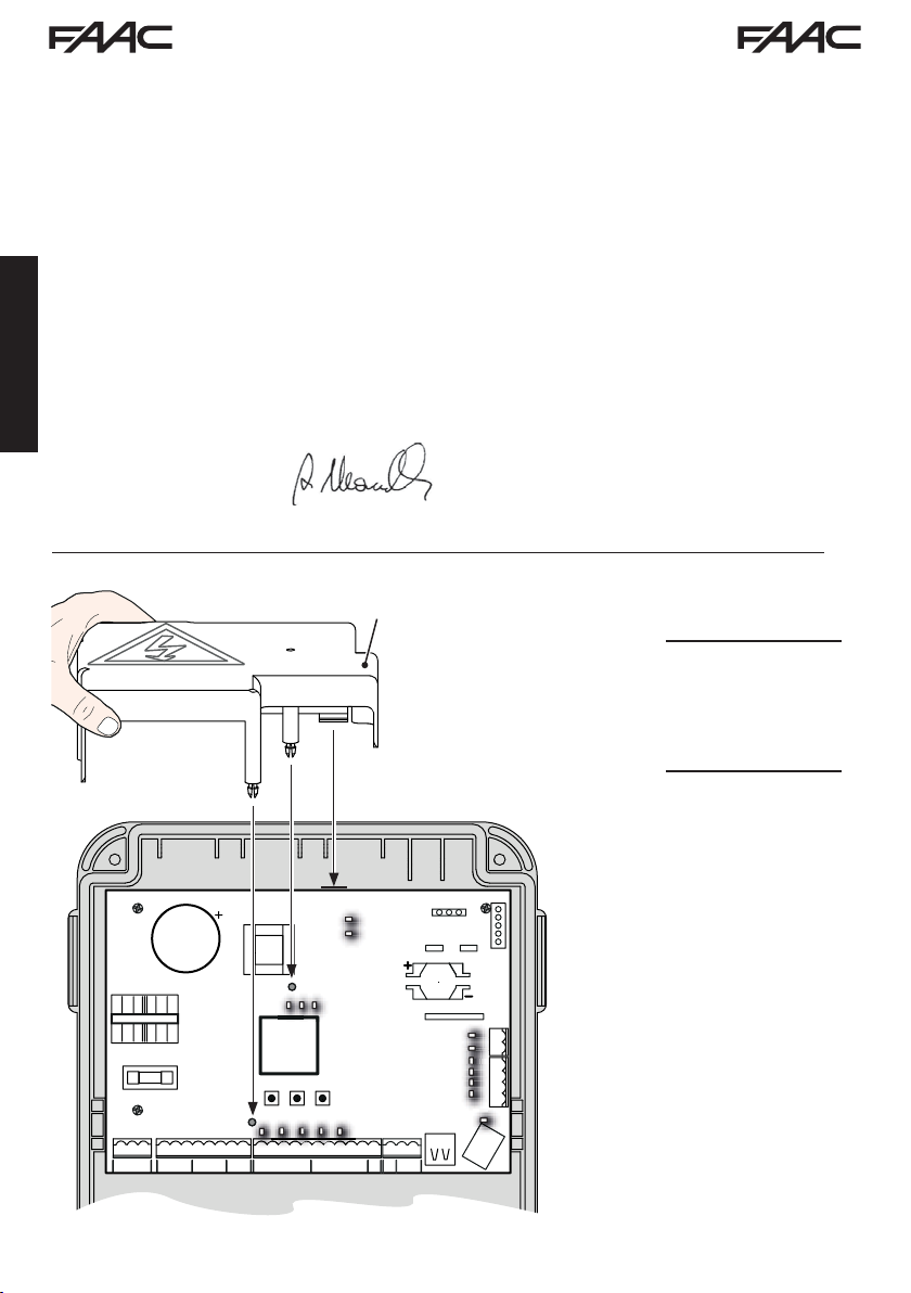
· Interrupt the electrical power
sup-ply before working on the
control unit. The protection cover
(1) needs to be installed before
switching on the power supply.
C
TF1
8.8.
E145 2 732784 - Rev. B
Page 3

WARNINGS FOR THE INSTALLER
GENERAL SAFETY OBLIGATIONS
1. ATTENTION! To ensure the safety of people, it
is important that you read all the following
instructions. Incorrect installation or incorrect
use of the product could cause serious harm
to people.
2. Carefully read the instructions before beginning
to install the product.
3. Do not leave packing materials (plastic, polystyrene, etc.) within reach of children as such
materials are potential sources of danger.
4. Store the instructions for future reference.
5. This product was designed and built strictly for
the use indicated in this documentation. Any
other use, not expressly indicated here, could
compromise the good condition/operation of
the product and/or be a source of danger.
6. FAAC S.p.A. declines all liability caused by improper use or use other than that for which the
automated system was intended.
7. Do not install the equipment in an explosive atmosphere: the presence of inflammable gas
or fumes is a serious danger to safety.
8. FAAC S.p.A. is not responsible for failure to
observe Good Technique in the construction
of the closing elements to be motorised, or for
any deformation that may occur during use.
9. The installation must conform to Standards EN 12453 and EN 12445.
For non-EU countries, to obtain an adequate
level of safety, the Standards mentioned above must be observed, in addition to national
legal regulations.
10. Before attempting any job on the system, cut out
electrical power and disconnect the batteries
if present.
11. The mains power supply of the automated system
must be fitted with an all-pole switch with contact opening distance of 3mm or greater. Use
of a 6A thermal breaker with all-pole circuit
break is recommended.
12. Make sure that a differential switch with threshold
of 0.03 A is fitted upstream of the system.
13. Make sure that the earthing system is perfectly
constructed, and connect metal parts of the
means of the closure to it.
14. The automated systems that feature a built-in anticrushing safety device in any case require a
functional check in accordance with the provisions of the Standards indicated at point 9.
15. The safety devices (EN 12978 standard) protect
any danger areas against mechanical movement Risks, such as crushing, dragging,
shearing, lifting.
16. Use of at least one indicator-light (e.g.: flashing
lamp) is recommended for every system, as
well as a warning sign adequately secured.
AAC S.p.A. declines all liability as concerns sa-
17. F
fety and efficient operation of the automated
system, if system components not produced
by FAAC S.p.A. are used.
18. For maintenance, strictly use original parts by
FAAC S.p.A.
19. Do not in any way modify the components of the
automated system.
20. The installer shall provide the User with all information concerning manual operation of the
system in case of an emergency.
21. Do not allow children or adults to stay near the
product while it is operating.
22. Keep radio controls or other pulse generators
away from children, to prevent the automated
system from being activated involuntarily.
23. Transit is allowed only when the automation is
fully open.
24. The User must not attempt any kind of repair or
direct action whatever and contact qualified
personnel only.
25. Anything not expressly specified in these instructions is not permitted.
ENGLISH
MEANING OF THE SYMBOLS USED
Important for the safety of persons and for the
good condition of the automated system.
E145 3 732784 - Rev. B
Notes on the characteristics and operation of
the product.
Page 4

INDEX
CE DECLARATION OF CONFORMITY .....................................................................................2
WARNINGS FOR THE INSTALLER ...........................................................................................3
1. TECHNICAL SPECIFICATIONS ............................................................................................5
2. PREPARING FOR INSTALLATION .......................................................................................6
3. BOARD LAYOUT ...................................................................................................................6
4. ELECTRICAL CONNECTIONS .............................................................................................8
4.1 J1 - Mains primary Power Supply ...................................................................................8
4.2 J2 - Motors and Flashing lamp .......................................................................................8
4.3 J3 - Low-voltage accessories - inputs/outputs .............................................................9
4.4 J12 - programmable outputs - electric locks .................................................................10
ENGLISH
4.5 J12 -J6 - LIMIT SWITCH AND GATECODER ...................................................................10
4.6 J10 - BUS-2EASY ACCESSORIes ..................................................................................1 1
BUS-2EASY photocells ........................................................................................................11
Address assignment of BUS-2EASY photocells ..................................................................12
Connection of BUS-2EASY photocells .................................................................................
BUS-2EASY
Connection - Address assignment of BUS-2EASY
4.7 J5 - XF module RAPID CONNECT
4.8 J14 - Decoder/Minidec/RP RAPID CONNECTOR
4.9 M1A - MODULe RAPID CONNECT
4.10 traditional photocells .....................................................................................................15
5. PROGRAMMING ...................................................................................................................18
5.1 Basic PROGRAMMING functions ...................................................................................19
5.2 Advanced PROGRAMMING functions ............................................................................24
5.6 BUS-2EASY DEVICE INSTALLATION .............................................................................30
5.6.1 BUS-2EASY DEVICE ENTRY .......................................................................................
Checking the securing devices entered on the board ..........................................................
5.4 TIME LEARNING - SETUP ................................................................................................32
5.5 TESTING THE AUTOMATED SYSTEM ............................................................................33
6. MEMORISING THE RADIO CODE ........................................................................................34
6.1 MEMORISING THE SLH/SLH LR RADIO CONTROLS ...................................................34
6.2 MEMORISING LC/RC RADIO CONTROLS (ONLY 433 MHz) .........................................35
6.2.1
6.3 MEMORISING DS RADIO CONTROLS ............................................................................36
6.4 DELETING THE RADIO CONTROLS ...............................................................................
7. START-UP ..............................................................................................................................38
7.1 CHECKING THE LEDs ......................................................................................................38
8. SIGNALLING ERRORS AND ALARMS ................................................................................39
8.1 ERRORS ............................................................................................................................39
8.2 ALARMS ............................................................................................................................40
9. TROUBLESHOOTING ...........................................................................................................41
10. MANAGING THE CONFIGURATION FILE – J8 USB .......................................................42
11. FUNCTION LOGICS ............................................................................................................45
encoder ...........................................................................................................13
Encoder ................................................13
OR .............................................................................14
...........................................................14
OR ............................................................................14
REMOTE MEMORISATION OF LC/RC RADIO CONTROLS ...................................36
12
30
31
37
E145 4 732784 - Rev. B
Page 5

CONTROL BOARD E145
We thank you for having chosen one of our products. FAAC is certain that from it you will obtain
all the performance you require. All our products are the result of years of experience in the field of
automated systems.
1. TECHNICAL SPECIFICATIONS
PURPOSE: this electronic control board has been
designed and built to control swing-leaf and/or
sliding gates for vehicle and pedestrian access
control.
Thanks to the innovative power supply switching
system, the board is able to automatically adapt
to different input voltages (from 90V~ to 260V~),
maintaining constant the output value of accessories, without being affected by variations.
Tab. Technical specifications
During programming you can choose between
different function logics.
2 programming levels are available from the board (BASIC and ADVANCED), using buttons and
LCD display.
This board also allows you the programming using
PC or MAC, connected via USB-B.
ENGLISH
Mains primary power supply
Power absorbed from mains
MAX load for motors
Accessories power supply
MAX. accessories current
Operating ambient temperature
Power supply safety fuses
W
ork time
Pause time
Motor power
Connector inputs
T
erminal board inputs
erminal board outputs
T
E145 5 732784 - Rev. B
With power supply switching from 90 V~ to 260 V~; 50/60Hz
*
stand By = 4W sleep < 2 W
*
FUNCTION THAT CAN BE ENABLED FROM A PC/MAC
800 W
"
24 V
+24V MAX 500 mA BUS 2easy MAX 500 mA
LOCK (FAAC) 12 V~ / 24 V"LOCK (not FAAC) 24 V
500mA (3A peak)
from -20°C to +55°C
F1 = F10AH250V
Self-learned through SETUP - (Max 4 min and 10 sec)
Programmable (from 0 to 9 min and 50 sec)
Programmable on 50 levels
Decoder/Minidec/RP, XF433/868 Module, USB-A, USB-B
Mains power supply from 90 to 260V ~, Inputs from IN1 to
IN5, Limit switch, BUS 2easy
Flashing lamp, Motors, Electric lock (LOCK1 and LOCK2),
OUT1 and OUT2 (programmable),
Accessories power supply
MAX ~ 800 W
"
Page 6
2. PREPARING FOR INSTALLATION
For safety reasons, it is important for people to carefully follow all the warnings and
instructions contained in this manual. Incorrect installation or incorrect use of the
product can cause serious harm to people. Before proceeding with product installation,
carefully read the entire manual. Keep these instructions for further reference.
Always cut off the electrical power before carrying out any work on the control unit
(connections, maintenance).
Always separate the power cables from the control and safety cables (button, receiver,
BUS 2easy encoder, photocells, etc.). Avoid any electrical disturbance using separate
sheathing or a shielded cable (with shield connected to the earth).
• Ensure that upstream of the system there is a suitable magnetothermic differential switch with
omnipolar cut-off, as provided for in current safety regulations.
Check for the presence of an adequate earthing system.
•
ENGLISH
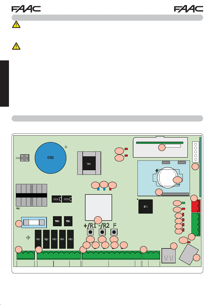
3. BOARD LAYOUT
DB1
FL1
F1
F1
J1
J1 J2 J3
PE N L
PENL
AC MAIN
C52
OC3
OC4
TH2 TH1
RL3 RL4RL1
RL2
J2
RL5
1 2 3 4 5 6 7 8
12 45678
3
M1
COM
OP
M2
COM
CL
LAMP
CL
OP
RADIO 1
TF1
DL16
DL16
5V
DL17
DL17
24V
DL13
DL13
ERROR
DL11
DL11
DL12
DL12
RADIO 2
RADIO XF 433-868
CONNECTIVITY
IC1
8.8.
LCD1
LCD
+/R1
SW1 SW2
SW1 SW2 SW3
DL8
DL9
DL8DL9
IN1
J3
9 10 11 12 13 14 15 16 17 18 19
91011 12 13 14 15 16 17 18 19
IN1
IN3
IN2
OP-A
STOPCLOP
OP-B
F
-/R2
SW3
DL7
DL6
DL7 DL6 DL5
IN2
IN3
IN4
IN5
IN4
---
FSW
DL5
IN5
J12
J12
20 21 22
20
OUT1
+
OUT2
+
24V
21
LOCK1LOCK
J5
M1A
22
2
J5
BAT1
CR2032
BAT1
DL14
DL15
J8
J8
DL14
DL15
DL4
DL4
DL3
DL3
DL2
DL2
DL1
DL1
BUS MON
BUS
DL10
DL10
FCC1 FCA1
FCC2 FCA2
RP/DEC
J4
J4
J10
J10
.
23
24
25
26
26 25 24 23
J6
J6
USB
J9
J9
USB-BUSB-A
E145 6 732784 - Rev. B
Page 7

LCD Signalling/Programming display
SW1 “+/R1” Programming button
SW2 “-/R2” Programming button
SW3 “F” Programming button
DL1 “FCC2” Input status control LED
DL2 “FCA2” Input status control LED
DL3 “FCC1” Input status control LED
DL4 “FCA1” Input status control LED
“IN5” Input status control LED (default
DL5
FSW OP
“IN4” Input status control LED (default FSW
DL6
CL)
“IN3” Input status control LED (default
DL7
STOP)
“IN2” Input status control LED (default
DL8
OPEN-B
“IN1” Input status control LED (default
DL9
OPEN-A
DL10 “
DL11 “
DL12 “
DL13 “
“BUS MON” BUS 2easy
DL14
LED
DL15 Device signalling LED to
)
)
)
USB
” Signalling LED
RADIO1-
XF” Signalling LED
RADIO2-
XF” Signalling LED
ERROR
” Error/alarm signalling LED
(OMNIDEC)
(OMNIDEC)
diagnostic signalling
BUS 2easy ACTIVE
DL16 Microprocessor power presence LED
"
Accessories power supply presence
+24V
DL17
LED
J1 90V~ a 260V~ Power supply connector
Motors and flashing lamp power supply
J2
connector
J3 Input/Output connector
Decoder/Minidec/RP Receiver connector:
Channel 1 (Decoder/Minidec/RP) - OPEN A
J4
(Total Opening)
Channel 2 (RP2) -
XF433/XF868 (OMNIDEC) receiver module
connector
J5
Channel 1
Channel 2
J6 Limit switch input connector
HOST USB-A
J8
DEVICE USB-B
J9
connector
BUS 2easy
J10
J12 OUT2 and LOCK 1-2 output connector
G-COM, WI-COM,
M1A
nector
BAT1 CR2032 buffer battery for board date/time
F1 Motor and power supply safety fuse
OPEN B (Partial Opening)
-
OPEN A
(Total Opening)
-
OPEN B
(Partial Opening)
for Mass Memories connector
for connection to
device connector
Net-COM module con-
PC/MAC
ENGLISH
E145 7 732784 - Rev. B
Page 8
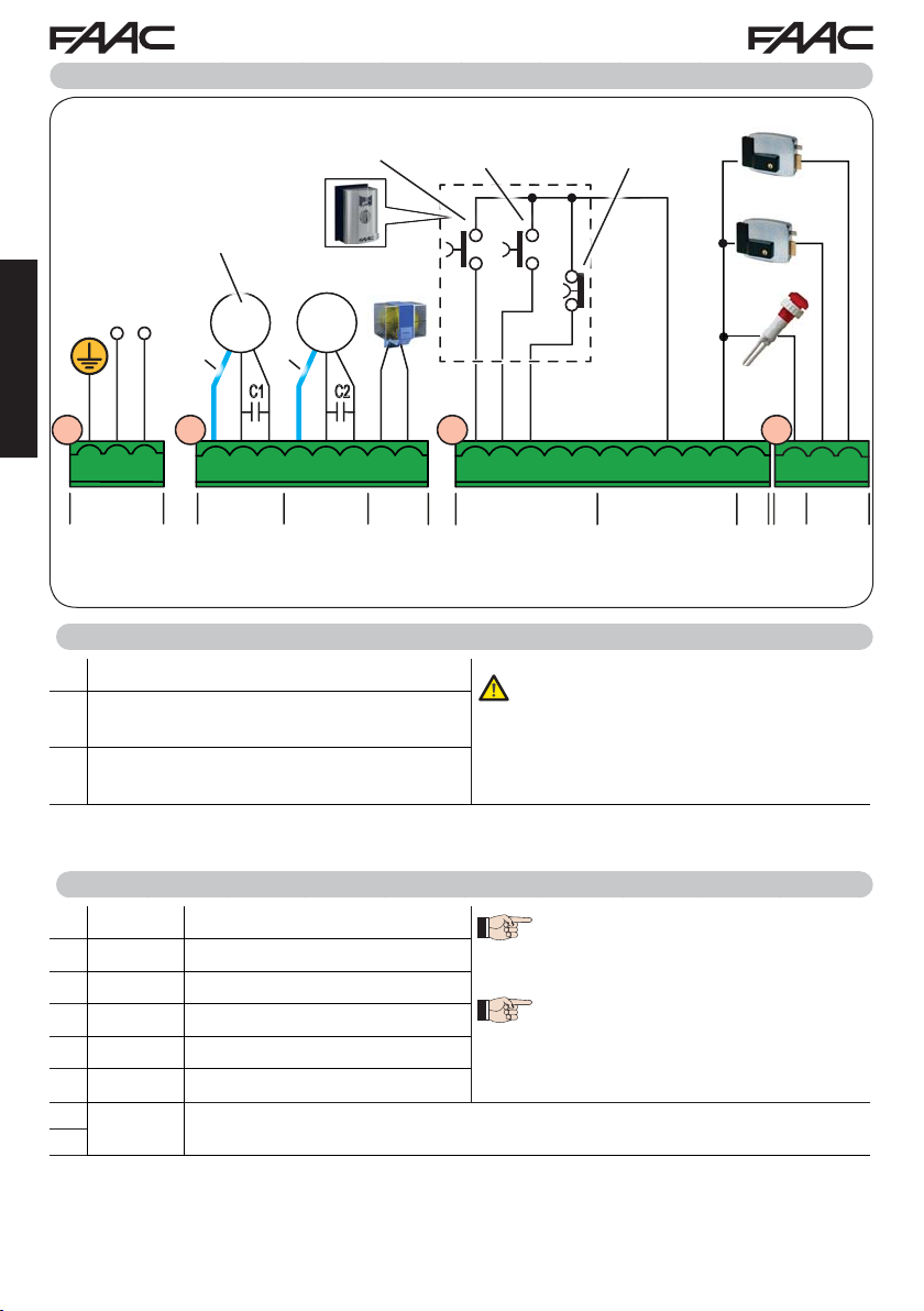
4. ELECTRICAL CONNECTIONS
OPEN A
Total gate opening
(contact N.O.)
Motor for SINGLE-LEAF or
FIRST LEAF when opening
(closes for the second)
MIN
90V~
MAX
260V~
50/60 Hz
Mot1 Mot2
230V~
MAX 60W
* *
ENGLISH
J1 J2 J3
J1
C1 C2
OPEN B
Partial gate opening (contact N.O.)
STOP
Gate stop
(contact
N.C.)
24V
3W
J12
J12J3J2
12V ~
24V
12V ~
24V
PE N L
PE N L
AC MAIN
*
Blue or grey
1 2 3 4 5 6 7 8
123
M1
COM OP CL
456
COM OP CL
78
LAMP
M2
Photocells and safety de-
vices: for connections, see
the related paragraph.
4.1 J1 - MAINS PRIMARY POWER SUPPLY
PE Earthing Connection
Power Supply Connection from 90 V~ to 260
N
V~ Neutral
Power Supply Connection from 90 V~ to 260
L
V~ Line
4.2 J2 - MOTORS AND FLASHING LAMP
1 M1 - COM Common contact motor 1
2 M1 - OP Opening phase motor 1
3 M1 - CL Closing phase motor 1
4 M2 - COM
5 M2 - OP Opening phase motor 2
6 M2 - CL Closing phase motor 2
7
LAMP Flashing lamp connection (MAX 60 W)
8
Common contact motor 2
19
OUT
OUT
1
MAX
100 mA
20 21 22
20
21
LOCK
2
{
9 10 11 12 13 14 15 16 17 18 19
IN2IN1IN3IN4IN
OP-A 1
5
-14-15-16+17+
FSW
OP
{
500 mA
For correct operation, you must con-
nect the switching power supply to the
system’s earthing conductor. Ensure
that upstream a suitable differential
magnetothermic switch has been installed.
M1 = first leaf when opening or single leaf
M2 = second leaf when opening - CAN-
NOT be used for single leaf
To verify correct wiring and direction
of motor rotation, (see 5.4 TIME LEAR-
NING - SETUP)
18910111213
24V
{
MAX
22
LOCK
2OP-B STOP CL
E145 8 732784 - Rev. B
Page 9
4.3 J3 - LOW-VOLTAGE ACCESSORIES - INPUTS/OUTPUTS
9 IN1
10 IN2
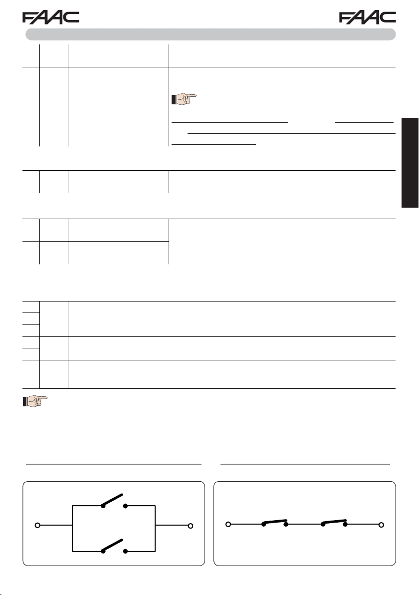
To install more than one OPEN A or OPEN B pulse generator, connect the N.O. contacts in
parallel (see related Fig.)
11 IN3
To install more than one STOP device, connect the N.C. contacts in series (see related Fig.).
If stop devices are NOT connected, jumper the terminals STOP and GND.
12 IN4
13 IN5
To install more than one safety device, connect the N.C. contacts in series (see related Fig.).
If safety devices are NOT connected, jumper terminals IN4 and IN5 and GND if the FAIL-SAFE
safety is not active; otherwise jumper IN4 and IN5 and OUT1 (FAIL-SAFE).
14
16
17
18
OPEN A contact - N.O.
TOT AL opening
OPEN B contact - N.O.
PARTIAL opening
STOP contact - N.C.
FSW CL contact - N.C.
closing safety
FSW OP contact - N.C.
opening safety
- GND Accessories power supply negative15
+ +24 Accessories power supply positive (MAX. load = 500mA)
Connect a button or other pulse generator which, by closing
a contact, commands TOTAL opening of both leaves.
Connect a button or other pulse generator which, by closing
a contact, commands the PARTIAL opening.
on 2-motor systems = 100% of leaf 1 opening;
on 1-motor systems = 50% of leaf 1 opening.
When a logic requiring a CLOSE (
the, OPEN B input automatically becomes CLOSE - N.O. (leaves closing command).
Connect a button or other pulse generator which, by opening
a contact, stops movement of the automated system.
Connect a photocell or other device which, by opening a contact, reverses the movement of the automated system during
opening (FSW OP) or during closing (FSW CL).
b, bC, C
) input is selected,
ENGLISH
19 OUT1
Fig. e.g.: Connecting 2 N.O. contacts in parallel. Fig. e.g.: Connecting 2 N.C. contacts in series.
E145 9 732784 - Rev. B
24 V" (Open Collector) programmable using function
default: always active.
Other programming options are available by programming via a PC/MAC (see dedicated
instructions).
o1
(advanced programming);
Page 10
4.4 J12 - PROGRAMMABLE OUTPUTS - ELECTRIC LOCKS
20 OUT2
21 LOCK 1
22 LOCK 2
ENGLISH
24 V" (Open Collector) programmable using the function
default: indicator light
Electric lock (12 V~ or 24 V")
operated 2 sec before opening
of leaf 1
Electric lock (12 V~ or 24 V") operated 2 sec before opening
of leaf 2
Other programming options are available by programming via a PC/MAC (see dedicated
instructions).
When BUS 2easy encoder is disabled, the electric
lock is operated before each opening (in whatever
position the stopped leaf is in).
When BUS 2easy encoder is enabled, the electric
lock is operated only before opening the closed leaf.
4.5 J12 -J6 - LIMIT SWITCH AND GATECODER
The limit switch contacts FCC1, FCA1, FCC2, FCA2 are all NC contacts.
They are programmable using the functions
If no limit switches are used, you DO NOT need to jumper the limit switch contacts
FCC1, FCA1, FCC2, FCA2.
You can however use a single GATECODER (only for single leaf); in this case, you do
not need to jumper the unused inputs to the earth.
Fig. Limit switch and GATECODER connections (maximum configuration:
FA
and
(basic programming) ; default: disabled.
FC
o2
(advanced programming);
).
햴
햲햳
헁
FCA1
헄
FCC1
헁
FCA2
헄
FCC2
26 25 24 23
J6
J6 J6
헁
GATECODER 1
GATECODER 2
FCA1
FCC1
FCA2
FCC2
26 25 24 23
J6
햴
헄
헁
헄
헁
FCA1, FCC1 and GATECODER1 correspond to LEAF 1;
FCA2, FCC2 and GATECODER2 correspond to LEAF 2.
E145 10 732784 - Rev. B
GATECODER 1
GATECODER 2
FCA1
FCC1
FCA2
FCC2
26 25 24 23
J6
J6
Page 11
4.6 J10 - BUS 2EASY ACCESSORIES
This board features a
of auxiliary BUS 2easy (MAX 16 pairs of photocells), encoder and control devices.
If no BUS 2easy accessories are used, leave the BUS 2easy connector free.
BUS 2easy photocells
Before connecting the photocells, arrange them for the duly address assignment, depending on their
position and operation mode:
Photocells during closing:
closing of the automated system - suitable for
protecting the closing area from risk of impact.
Photocells during opening:
opening of the automated system - suitable for
protecting the opening area from risk of impact.
Photocells during opening/closing:
both the opening and closing - suitable for protec-
ting the entire movement area from risk of impact.
Pulse generators: used as pulse generators for
opening the automated system
BUS 2easy
circuit for facilitating connection to the safety devices of a high number
trip only during the
Opening/clo-
trip only during the
trip during
.
Closing
safety devices
sing safety
devices
Opening
safety devices
ENGLISH
E145 11 732784 - Rev. B
Page 12
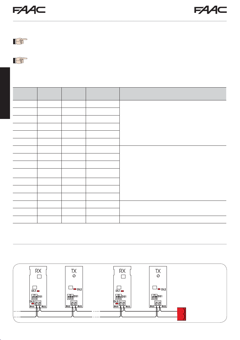
Address assignment of BUS 2easy photocells
To assign the address to each pair of photocells, you must set the Dip-Switches (DS1) located on the
transmitter and corresponding receiver.
The transmitter and receiver of a pair of photocells must have the same
DIP-SWITCH setting.
Two or more pairs of photocells must not have the same DIP-SWITCH setting.
Other programming options are available by programming via a PC/MAC (see dedicated
instructions).
Dip1 Dip2 Dip3 Dip4 TYPE OF PHOTOCELLS
OFF OFF OFF OFF
ENGLISH
OFF OFF OFF ON
OFF OFF ON OFF
OFF OFF ON ON
OPENING (max 6 pairs)
OFF ON ON OFF
OFF ON ON ON
ON OFF OFF OFF
ON OFF OFF ON
ON OFF ON OFF
ON OFF ON ON
CLOSING (max 7 pairs)
ON ON OFF OFF
ON ON OFF ON
ON ON ON OFF
OFF ON OFF OFF
OFF ON OFF ON
ON ON ON ON
OPENING and CLOSING (max 2 pairs)
OPEN PULSE (1 pair)
Connection of BUS 2easy photocells
For connecting you have to use two cables without polarity (see the specific device instructions).
DL1
= Alignment
DL2
= BUS 2easy status/
Power supply
DS1
= Programming
Dip-switches
BUS 2easy
J10
E145 12 732784 - Rev. B
Page 13
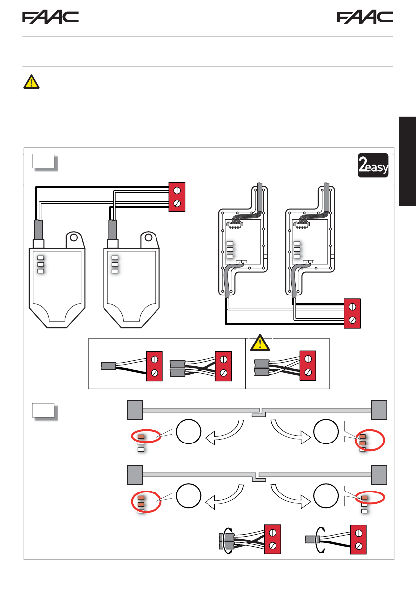
BUS 2easy encoder
BUS 2easy encoder connection is done using the bi-polar cables supplied with.
Connection - Address assignment of BUS 2easy Encoder
The polarity of the BUS 2easy line connection determines the correspondence of the
encoder to one leaf or the other.
pay careful attention to the indications of the status LEDs located on the body of each
encoder.
LEAF 1 opens first and closes last.
A
SAFEcoder S800 ENC
J10
BUS-2easy
DL
DL2
DL
3
1
DL1
DL2
DL3
DL1
DL2
DL3
DL
DL2
DL
3
1
ENGLISH
J10
BUS-2easy
: 2 LED on
M1
B
M2
: 1 LED on
DL1
DL2
DL3
DL1
DL2
DL3
· Note: to correct the coupling of the encoder with motor
M1 or M2, swap both wires on the terminals.
E145 13 732784 - Rev. B
M2
M1
M1
M2
DL1
DL2
DL3
DL1
DL2
DL3
Page 14
RADIO XF 433-868
RADIO 1
DL12
DL11
RADIO 2
J5
J4
RP/DEC
CONNECTIVITY
Tab. BUS 2easy Encoder LEDs Status
LED ON FLASHING OFF
Power present
Communication present
DL1
Power present
Communication absent
DL1 must always be on to confirm correct encoder/board connection.
Leaf 1 / Leaf 2
DL2
DL2 indicates the leaf on which the encoder is installed; it must be on for leaf 1 and off for
leaf 2.
Stationary leaf Leaf in motion Stationary leaf
DL3
DL3
indicates pulse reading during leaf movement using steady flashing. In stationary status
of the leaf, the DL3 can be either on or off.
In case of incorrect connection (DL2 on or off for both of the encoders), during the
ENGLISH
BUS 2easy accessories learning procedure, the DL1 leds of both encoders are
FLASHING.
4.7 J5 - XF MODULE RAPID CONNECT OR
Plug-in rapid connector dedicated to OMNIDEC
2-channel decoding module.
ALW A YS cut off power to the board BEFORE inserting/removing the module.
Power absent
Communication absent
4.8 J14 - DECODER/MINIDEC/RP RAPID CONNECTOR
Rapid connector dedicated to Decoder/Minidec/RP/RP2.
Connect the accessory with the components facing inside the board.
ALWAYS cut off power to the board BEFORE inserting/removing plug-in boards.
The RP2 2-channel receiver lets you control two different radio channels of the automated system
(OPEN A and OPEN B/CLOSE) using a 2-channel radio control.
The 1-channel receiver (Decoder/Minidec/RP) lets you control only one radio channel: OPEN
Other programming options are available by programming via a PC/MAC (see dedicated
instructions).
4.9 M1A - MODULE RAPID CONNECTOR
Plug-in connector dedicated to G-COM, WI-COM, Net-COM modules.
ALWAYS cut off power to the board BEFORE inserting/removing the module.
Other programming options are available by programming via a PC/MAC (see dedicated
instructions).
E145 14 732784 - Rev. B
A.
Page 15
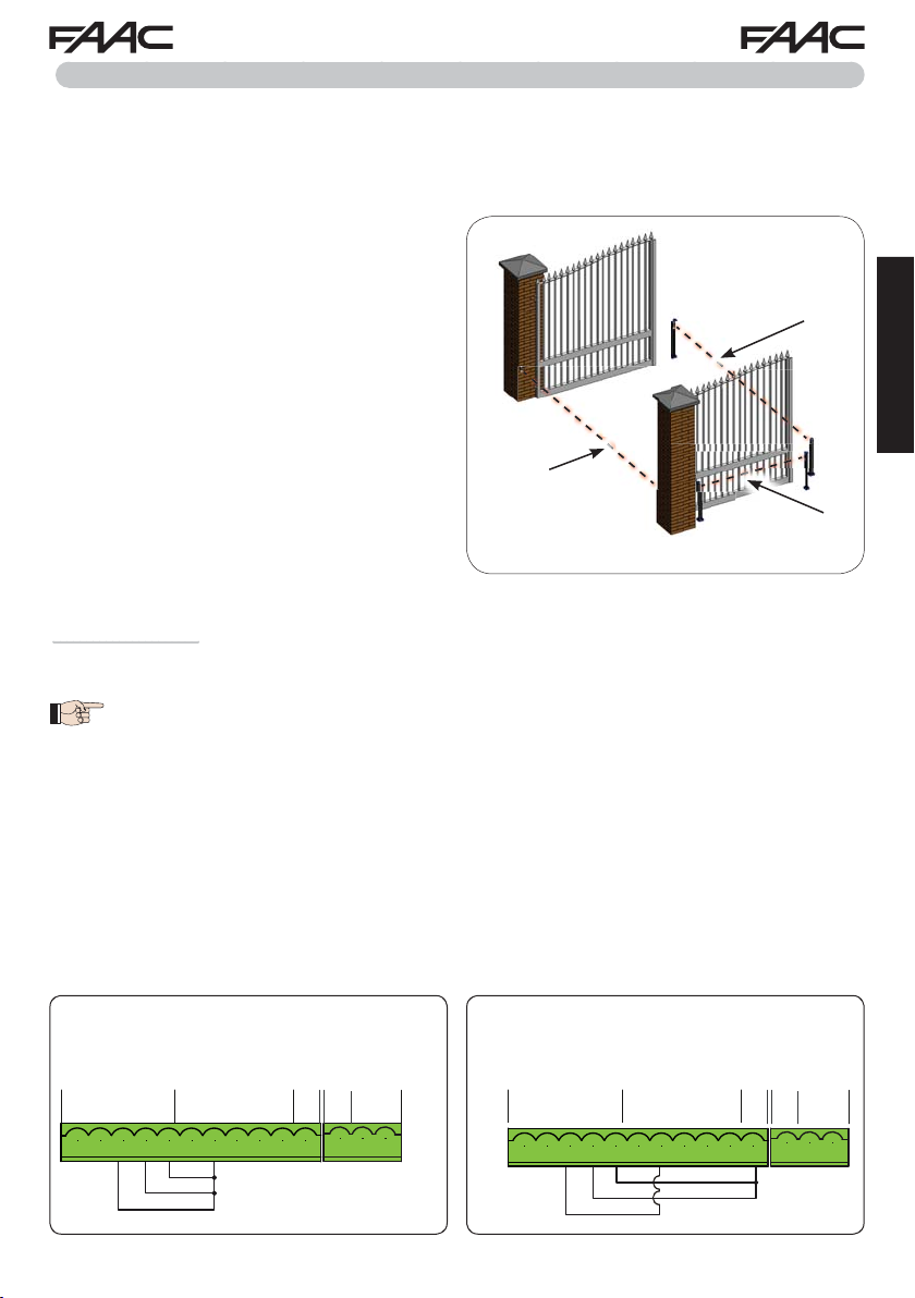
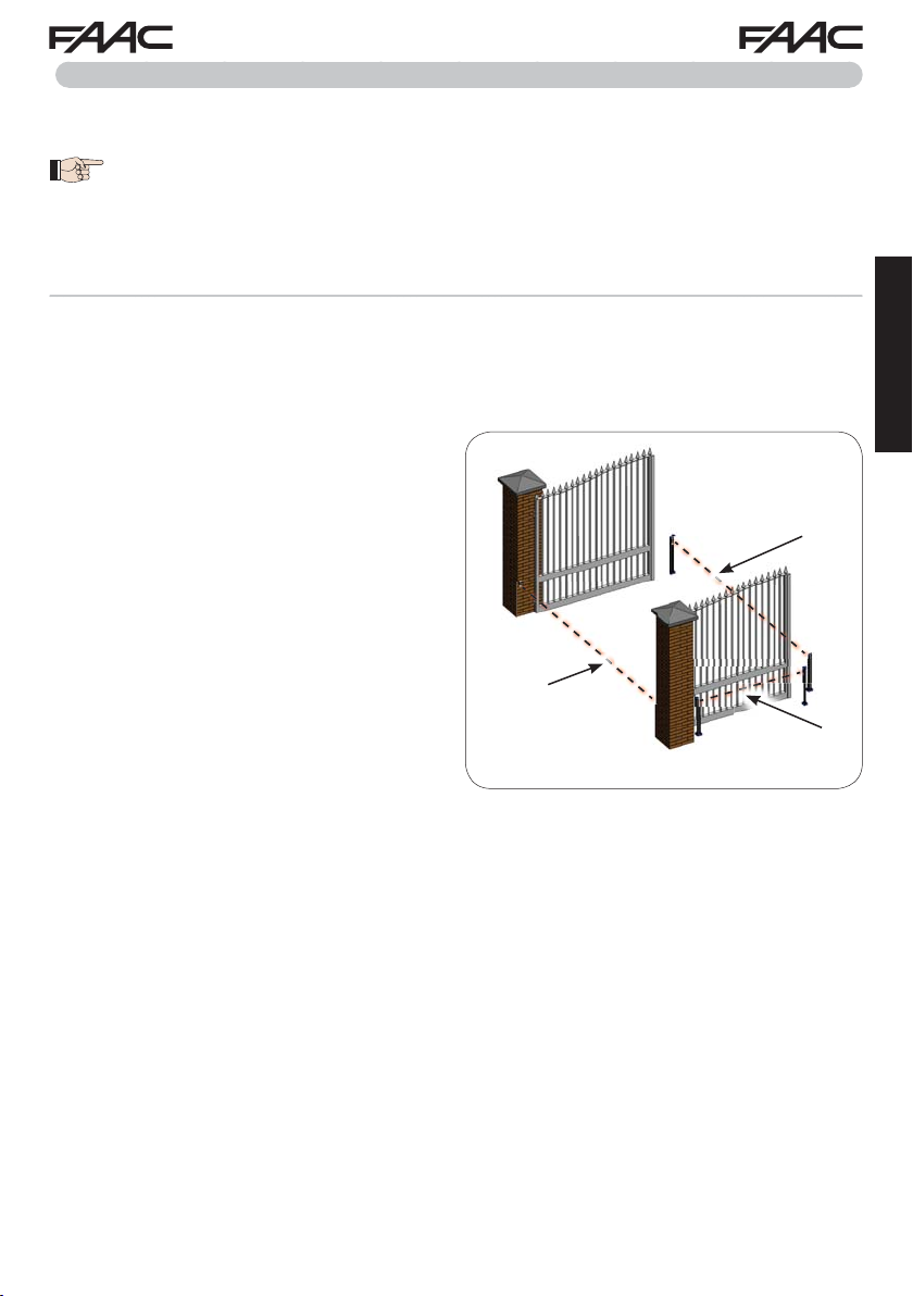
4.10 TRADITIONAL PHOTOCELLS
o1
01
This board lets you use traditional photocells (contact N.C. with relay).
Before connecting the photocells, it is best to identify the operating type, which depends on the movement area they have to protect:
Closing photocells:
trip only during the automated system closing - suitable for protecting the
closing area from risk of impact.
Opening photocells:
trip only during the auto-
Safety devices for
opening/closing
mated system opening - suitable for protecting the
opening area from risk of impact.
Photocells for opening/closing:
trip during both
the opening and closing - suitable for protecting the
entire movement area from risk of impact.
Pulse generators: used as pulse generators for
opening the automated system
.
Closing
safety devices
Opening
safety devices
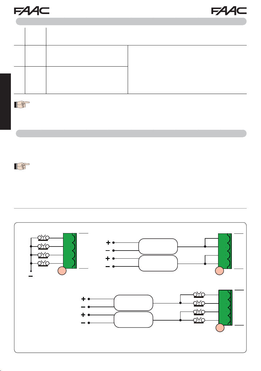
Fail Safe function
This function lets you monitor the correct alignment and operation of the photocells before each move-
=
ment. To enable the Fail Safe function, enter the ADVANCED Programming and set the
With Fail Safe disabled: connect the transmitter (TX) power supply to terminals 15 and
o1
function.
01
18 of J3.
With Fail Safe enabled:
Then jumper the unused safety inputs with OUT1.
OUT1.
connect the power supply negative of the transmitters (TX) to
Hereafter are provided the drawings for some connection examples.
ENGLISH
No safety device and no stop device
FAIL SAFE disabled
9 10 11 12 13 14 15 16 17 18 19
IN1 IN2 IN3 IN4 IN5
OP-A OP-B STOP CL FSW OP
---
+
20 21 22
OUT1 OUT2 LK1 LK2
+
24V
9 10 11 12 13 14 15 16 17 18 19 20 21 22
No safety device and no stop device
FAIL SAFE enabled
9 10 11 12 13 14 15 16 17 18 19
IN1 IN2 IN3 IN4 IN5
OP-A OP-B STOP CL FSW OP
---
+
20 21 22
OUT1 OUT2 LK1 LK2
+
24V
9 10 11 12 13 14 15 16 17 18 19 20 21 22
E145 15 732784 - Rev. B
Page 16
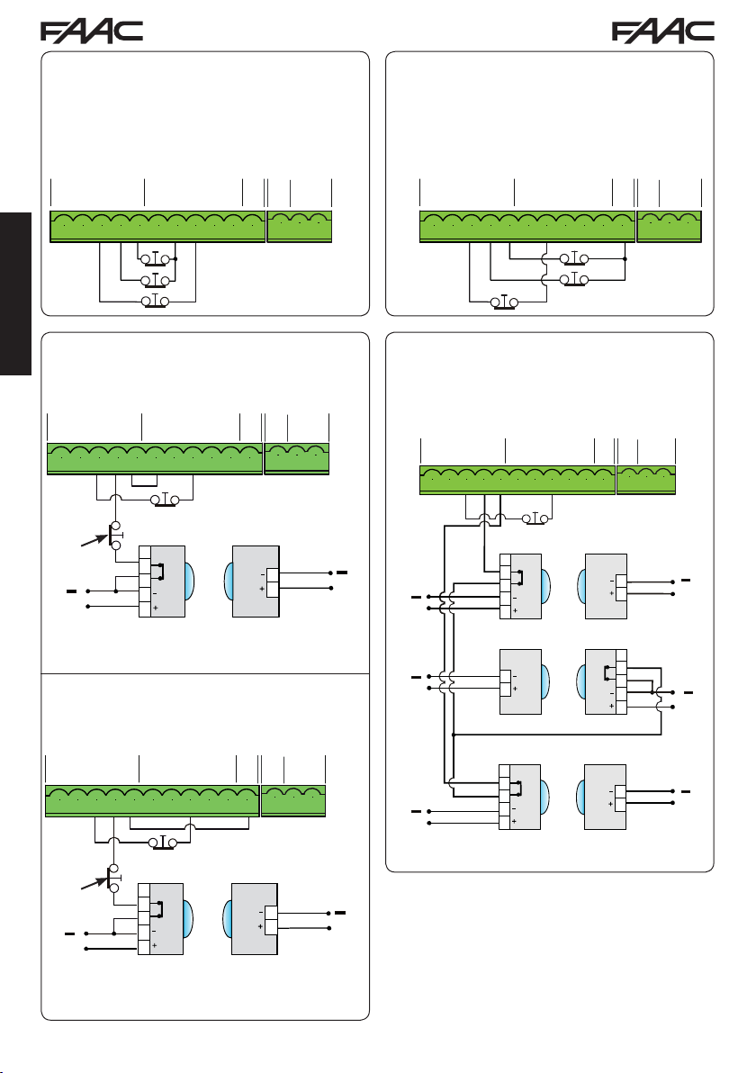
One closing safety device, one opening safety device, one STOP device.
FAIL SAFE disabled
One closing safety device, one opening safety device, one STOP device.
FAIL SAFE enabled
9 10 11 12 13 14 15 16 17 18 19
IN1 IN2 IN3 IN4 IN5
OP-A OP-B STOP CL FSW OP
---
+
20 21 22
OUT1 OUT2 LK1 LK2
+
24V
ENGLISH
One pair of closing photocells.
FAIL SAFE disabled
9 10 11 12 13 14 15 16 17 18 19
IN1 IN2 IN3 IN4 IN5
OP-A OP-B STOP CL FSW OP
---
+
20 21 22
+
OUT1 OUT2 LK1 LK2
24V
9 10 11 12 13 14 15 16 17 18 19 20 21 22
Other
safety
devices
헁
+
헄
One pair of closing photocells.
FAIL SAFE enabled
RX CL
1
2
3
4
5
TX CL
1
2
9 10 11 12 13 14 15 16 17 18 19
IN1 IN2 IN3 IN4 IN5
OP-A OP-B STOP CL FSW OP
---
+
20 21 22
OUT1 OUT2 LK1 LK2
+
24V
9 10 11 12 13 14 15 16 17 18 19 20 21 22 9 10 11 12 13 14 15 16 17 18 19 20 21 22
One pair of closing photocells, one pair of
opening photocells and one pair for opening/
closing.
FAIL SAFE disabled
9 10 11 12 13 14 15 16 17 18 19
IN1 IN2 IN3 IN4 IN5
OP-A OP-B STOP CL FSW OP
---
+
9 10 11 12 13 14 15 16 17 18 19 20 21 22
RX CL
1
헁
헄
+
헁
+
헄
헁
헄
+
2
3
4
5
TX OP/CL RX OP/CL
1
2
20 21 22
OUT1 OUT2 LK1 LK2
+
24V
TX CL
1
2
1
2
3
4
5
헁
+
헄
헁
헄
+
9 10 11 12 13 14 15 16 17 18 19
IN1 IN2 IN3 IN4 IN5
OP-A OP-B STOP CL FSW OP
---
+
9 10 11 12 13 14 15 16 17 18 19 20 21 22
Other
safety
devices
헁
헄
+
RX CL
1
2
3
4
5
20 21 22
OUT1 OUT2 LK1 LK2
+
24V
TX CL
RX OP
1
2
3
헁
헄
+
1
2
헅
헄
+
4
5
TX OP
1
2
E145 16 732784 - Rev. B
헁
+
헄
Page 17

헁
헄
헁
헄
Two pairs of closing photocells.
FAIL SAFE disabled
One pair of opening photocells and one for
closing.
FAIL SAFE disabled
9 10 11 12 13 14 15 16 17 18 19
IN1 IN2 IN3 IN4 IN5
OP-A OP-B STOP CL FSW OP
---
+
20 21 22
+
OUT1 OUT2 LK1 LK2
24V
9 10 11 12 13 14 15 16 17 18 19 20 21 22
Other
safety
devices
헁
+
헄
헁
헄
+
RX CL1
1
2
3
4
5
TX CL2 RX CL2
1
2
One pair of opening photocells.
FAIL SAFE disabled
9 10 11 12 13 14 15 16 17 18 19
IN1 IN2 IN3 IN4 IN5
OP-A OP-B STOP CL FSW OP
---
TX CL1
OUT1 OUT2 LK1 LK2
+
+
24V
20 21 22
1
2
1
2
3
4
5
9 10 11 12 13 14 15 16 17 18 19 20 21 22
9 10 11 12 13 14 15 16 17 18 19
IN1 IN2 IN3 IN4 IN5
OP-A OP-B STOP CL FSW OP
---
+
20 21 22
+
OUT1 OUT2 LK1 LK2
24V
9 10 11 12 13 14 15 16 17 18 19 20 21 22
RX CL
헁
헄
+
+
헁
헄
+
+
1
2
3
4
5
TX OP RX OP
1
2
One pair of closing photocells
and one for opening/closing.
FAIL SAFE disabled
9 10 11 12 13 14 15 16 17 18 19
IN1 IN2 IN3 IN4 IN5
OP-A OP-B STOP CL FSW OP
---
TX CL
1
2
1
2
3
4
5
+
24V
+
+
20 21 22
OUT1 OUT2 LK1 LK2
+
헁
헄
ENGLISH
헁
헄
9 10 11 12 13 14 15 16 17 18 19 20 21 22
Other
safety
devices
헁
+
헄
RX OP
1
2
3
4
5
TX OP
1
2
헁
헄
헁
+
헄
+
헁
헄
+
RX CL
1
2
3
4
5
TX OP/CL RX OP/CL
1
2
E145 17 732784 - Rev. B
TX CL
1
2
1
2
3
4
5
헁
헄
+
헁
헄
+
Page 18

5. PROGRAMMING
-
www.faacgroup.c om
-
+
-
1
Programming is divided in two levels:
• BASIC programming
• ADVANCED programming
The programming phases are (see Tab.):
1. to access PROGRAMMING (1A or 1B);
2. to show the set values and modify them, if
you want. Changing the values is effective
immediately, while the final memorisation must
be carried out upon exiting programming (
3. exit the programming by using
Y to SAVE the configuration you just
Select
performed, otherwise select
THOUT SAVING any changes.
ENGLISH
You can EXIT programming at anytime:
• press and hold F and then also
directly to
St.
+
F
-/R2
Tab. BASIC programming phases.
PRESS AND HOLD
F:
THE FIRST
FUNCTION
APPEARS
F
1
RELEASE F:
THE FUNCTION
IS
VALUE
DISPLAYED
F
St function.
no to EXIT WI-
to switch
USING+OR
SCROLL THE
VALUES
AVAILABLE
THE DESIRED
UNTIL
ONE
-/
+/
R1
St).
R2
This board also allows programming using a PC
or MAC.
This programming requires connection to PC/MAC
via USB cable and USB-B relevant port.
The programming SOFTWARE with relevant instructions, must be downloaded from the website:
www.faacgroup.com
The programming using a PC/MAC, with the de-
fault PASSWORD does not inhibit the programming by board.
The writing
PC will be displayed in
correspondence with the modified values. Notes:
when you modify the values by board the previous
PC/MAC programming will be overwrote.
The default password is 0000.
The programming using a PC/MAC, with a modified PASSWORD (different from the default one),
will inhibit the programming by board. If one of the
buttons is pressed, the display will show
gramming for 5 sec and changes will be allowed
only by PC /MAC.
,
PRESS F:
TO MOVE TO
NEXT
THE
FUNCTION
F
1
FUNCTION St
(LAST FUNCTION)
SELECT Y TO SAVE
PROGRAMMING
THE
OTHERWISE
no TO EXIT
SELECT
PROGRAMMING
THE
SAVING
WITHOUT
PRESS
TO CONFIRM;
F
AT THE END THE
DISPLAY
VISUALIZE THE
TO
AUTOMATED
F
PC pro-
THE BUTTON
RETURNS
SYSTEM
STA TUS
Tab. ADVANCED programming phases
PRESS AND HOLD
AND THEN ALSO
F
:
THE FIRST
FUNCTION
APPEARS
+
F
+/
R1
1
RELEASE THE
THE FUNCTION
BUTTONS
IS
VALUE
DISPLAYED
+/
R1
:
F
+
USING+OR
SCROLL THE
VALUES
AVAILABLE
THE THE
UNTIL
ONE
DESIRED
+/
R1
-/
R2
,
PRESS F:
TO MOVE TO
NEXT
THE
FUNCTION
F
FUNCTION St
(LAST FUNCTION)
1
SELECT Y TO SAVE
PROGRAMMING
THE
OTHERWISE
no TO EXIT
SELECT
PROGRAMMING
THE
SAVING
WITHOUT
1
THE FUNCTION IS DISPLAYED UNTIL YOU HOLD
PRESS
THE BUTTON
TO CONFIRM;
F
AT THE END THE
RETURNS
DISPLAY
VISUALIZE THE
TO
AUTOMATED
STA TUS
F
SYSTEM
E145 18 732784 - Rev. B
Page 19

5.1 BASIC PROGRAMMING FUNCTIONS
Display Basic Function
CF
MOTOR TYPE:
Displays and allows you to change the motor type set on the board:
1 Motors for swing-leaf gates
2 Motors for sliding gates
PC Mixed configuration from a PC/MAC (e.g.: a swing and a slide)
At the time of changing the set motor type on the board, the
relevant defaults are uploaded.
dF
DEFAULT:
Y indicates that all the set values correspond to the default values.
no indicates that one or more set values are different from the default.
Y if you want to restore the default settings.
Set
LO
FUNCTION LOGICS:
E Semi-automatic
EP Semi-automatic Step-by-Step
S Automatic Safety Devices
SA Automatic with reversal during pause
SP Automatic Step-by-Step Safety Devices
A1 Automatic 1
A Automatic
AP Automatic Step-by-Step
At Automatic timer
b Semi-automatic “b”
bC Mixed (Pulses for opening / Dead-man commands for closing)
C Dead-man
CU Logic modified from a PC/MAC
Default
ENGLISH
Y
E
When a logic requiring a CLOSE (b, bC, C ), input is selected,
the OPEN B inputs will automatically be changed to CLOSE. , if
you choose a logic that does not require the use of CLOSE inputs,
these inputs will change to OPEN B. The simultaneous presence
of CLOSE and OPEN B is possible only using the PC/MAC software.
For a description of how the logics operate, see the related paragraph.
E145 19 732784 - Rev. B
Page 20

Display Basic Function
PA
ENGLISH
PAUSE A TIME (visualised only with Automatic logics)
Is the pause time in a TOTAL opening (it is enabled only if a logic with pause
time has been selected).
Adjustable from
Next the value 59, the viewing changes to minutes and tenths of a second
(separated by a decimal point) and time is adjusted in 10-second steps up to
the maximum value of
e.g.: if the display shows
00 to 59 sec, in 1-second steps.
9.5
minutes.
2.5, the time is 2 min and 50 sec.
Default
30
Pb
Mn
PAUSE TIME B (visualised only with Automatic logics):
Is the pause time in a PARTIAL opening (it is effective only if a logic with pause
time has been selected).
Adjustable from
Next the value 59, the viewing changes to minutes and tenths of a second
(separated by a decimal point) and time is adjusted in 10-second steps up to
the maximum value of
Es: if the display shows
NR. OF MOTORS:
You can select the number of motors present in the system:
00 to 59 sec, in 1-second steps.
9.5
minutes.
2.5, the time is 2 min and 50 sec.
1 = 1 motor
2 = 2 motors
If the SETUP is performed with only one motor, and later two mo-
tors are used, the board will signal error
which can be deleted by repeating the SETUP with two motors or
by returning to one motor.
If a SETUP is performed with two motors and later only one is used,
the board will not signal an error. Only the motor connected to input
M1 will move.
When programming from a PC/MAC, you can select different partial
openings.
14 - configuration error,
30
2
(swing-
leaf)
1
(sliding)
E145 20 732784 - Rev. B
Page 21

Display Basic Function
F1
MOTOR 1 POWER:
You can adjust the maximum power of motor 1, which is the same during
both opening and closing.
01 = minimum power
50 = maximum power
If the power is modified, we recommend performing a new SETUP
- see the related paragraph.
If hydraulic motors are used, power must be programmed to maximum
50).
level (
Default
25
F2
En
FA
MOTOR 2 POWER (visualised only with the function Mn = 2):
You can adjust the maximum power of motor 2, which is the same during
both opening and closing.
01 = minimum power
50 = maximum power
If the power is modified, we recommend performing a new SETUP
- see the related paragraph.
If hydraulic motors are used, power must be programmed to maximum
50).
level (
ENCODER USE:
You can enable/disable the use of encoders (both BUS and GATECODER
encoders):
Y = encoders on both motors
no = encoders disabled
LIMIT SWITCH WHEN OPENING (displayed only if function CF = 1 or
CF = PC):
Lets you set or disable use of the opening limit switch on swing-leaves .
In case of mixed configuration (CF = PC) this function works only
on the swing-leaves. The limit switch on the SLIDING leaf is required
and determines when the leaf stops.
no = opening limit switches disabled
01 = the limit switch determines the stopping of motion
02 = the limit switch determines the start of deceleration
25
no
no
ENGLISH
After having changed the value of this function, SETUP is required:
the card will signal error
performed again or until the previous value is restored
E145 21 732784 - Rev. B
14 (configuration error) until the SETUP is
Page 22

Display Basic Function
Default
FC
ENGLISH
Br
LIMIT SWITCH WHEN CLOSING (displayed only if function CF = 1 or
CF = PC):
Lets you set or disable use of the closing limit switch on swing-leaves.
In case of mixed configuration (CF = PC) this function works only
on the swing-leaf. The limit switch on the SLIDING leaf is required
and determines when the leaf stops.
no = closing limit switches disabled
01 = the limit switch determines the stopping of motion
02 = the limit switch determines the start of deceleration
After having changed the value of this function, SETUP is required:
the card will signal error
performed again or until the previous value is restored.
SLIDING LEAF BRAKING (displayed only if function CF = 2 or CF
=
PC):
Lets you set the braking time of sliding leaves.
14 (configuration error) until the SETUP is
00 = braking disabled
10 = maximum braking time
no
05
Cd
bu
E145 22 732784 - Rev. B
DELA Y FOR CLOSING LEAF (visualised only with the function Mn = 2):
Is the delay time for starting leaf 1 closing with respect to leaf 2. Makes it
possible to avoid overlapping of the two leaves.
Adjustable from
Next the value 59, the viewing changes to minutes and tenths of a second
(separated by a decimal point) and time is adjusted in 10-second steps up to
the maximum value of
e.g.: if the display shows
BUS 2easy DEVICES ENTRY:
See the related paragraph.
00 to 59 sec, in 1- second steps.
3
minutes.
1.2, the time is 1 min and 20 sec
05
no
Page 23

Display Basic Function
-
M2
MOTOR 2 dead-man DRIVE mode (visualised only with the function
Mn = 2)
+/
R1
OPENS (visualising
-/
R2
CLOSES (visualising
Default
--
oP) until the button is held down
cL) until the button is held down
M1
tL
St
MOTOR 1 dead-man DRIVE mode
+/
R1
OPENS (visualising
-/
R2
CLOSES (visualising
WORK TIME LEARNING (SETUP):
See the related paragraph.
AUTOMATED SYSTEM STATUS:
You can exit programming, choosing whether or not to save the configuration
you just performed.
1. set the choice:
oP) until the button is held down
cL) until the button is held down
Y to SAVE and EXIT the programming
no to EXIT the programming WITHOUT SAVING
2. press the button F to confirm; at the end the display returns to visualize
the automated system status:
00 = CLOSED
01 = OPEN
02 = Stationary then “OPENS”
03 = Stationary then “CLOSES”
04 = In “PAUSE”
05 = during Opening
06 = during Closing
07 = FAIL SAFE in progress
08 = checking BUS 2easy devices in progress
09 = Pre-flash then “OPENS”
10 = Pre-flash then “CLOSES”
11 = Emergency open
12 = Emergency close
HP = Hold position
--
ENGLISH
--
Y
WARNING If power is lost to the board prior to confirmation (step
2.), all changes made will be lost.
You can EXIT programming at any time: press and hold F and
then also
+
F
-/R2
E145 23 732784 - Rev. B
to switch directly to St.
Page 24

5.2 ADVANCED PROGRAMMING FUNCTIONS
Display Advanced Function
bo
ENGLISH
cS
TIME OF MAXIMUM POWER AT STARTING:
You can set the starting time. During start the motors work at maximum power
for starting the movement.
Adjustable from
selected with
FINAL STROKE WHEN CLOSING (RAM STROKE) (NOT displayed if
function
Lets you enable/disable the ram stroke on swing-leaves.
The ram stroke facilitates latching of the electric lock by activating the motors
at maximum power during final closing.
FC = 1):
Y = enabled (for 2 sec)
no = disabled
In case of systems with an absolute encoder, to enable this function
a setup must be performed using the automatic leaf stop on the
mechanical contact point.
Default
01
00 to 10 sec, in 1-second steps (ignoring the power level
F1 and F2).
no
rS
REVERSE STROKE WHEN OPENING displayed if function FC = 1):
Lets you enable/disable the reverse stroke on leaf doors.
The reverse stroke facilitates unlatching of the electric lock. When the automatic system is closed, before starting to open, the motors give a brief push
to close.
Y = enabled (for 2 sec)
no = disabled
In case of systems with an absolute encoder, to enable this function
a setup must be performed using the automatic leaf stop on the
mechanical contact point.
E145 24 732784 - Rev. B
no
Page 25

Display Advanced Function
Default
Od
r1
r2
DELA Y FOR OPENING LEAF (visualised only with the function Mn = 2):
You can set the delay time for starting leaf 2 opening with respect to leaf 1, in
order to avoid overlapping of the two leaves.
Adjustable from
Next the value 59, the viewing changes to minutes and tenths of a second
(separated by a decimal point) and time is adjusted in 10-second steps up to
the maximum value of
e.g.: if the display shows
LEAF 1 DECELERATION:
You can adjust the deceleration space as a percentage of the total travel of
leaf 1.
Adjustable from
00 to 59 sec, in 1- second steps.
1.3
minutes.
1.2, the time is 1 min and 20 sec.
00
to 99
%, in 1% steps.
00 = no deceleration
01 = minimum deceleration space
99 = maximum deceleration space
LEAF 2 DECELERATION (visualised only with the function Mn = 2):
You can adjust the deceleration space as a percentage of the total travel of
leaf 2.
Adjustable from
00
to 99
%, in 1% steps.
00 = no deceleration
01 = minimum deceleration space
99 = maximum deceleration space
02
ENGLISH
20
20
PF
PRE-FLASHING:
You can enable/disable the pre-flashing. Pre-flashing duration = 3 sec.
You can choose:
no = disabled
OC = pre-flashing before each movement
CL = pre-flashing before a closing movement
OP = pre-flashing before an opening movement
PA = pre-flashing only at the end of the pause time
E145 25 732784 - Rev. B
no
Page 26

Display Advanced Function
Ph
CLOSING PHOTOCELLS:
The intervention of closing photocells causes the reversing of automated
system (opening).
You can choose:
Y = operate the reversal only after the photocells are released
no = operate the reversal immediately
Default
no
Ad
ENGLISH
EC
r8
ADMAP FUNCTION:
Allows operation in compliance with French regulation NFP 25/362.
Y = enabled
no = disabled
ANTI-CRUSHING SENSITIVITY (visualised only with the function En
=
Y):
Varying this function varies the amount of time after which, in case of obstacle, the board commands reversal of the leaves, or it will command a stop
if the leaves are in the contact point search space (see the parameter
The fourth consecutive obstacle detected in the same direction and position
will be defined as a contact point and the leaf will stop in that position.
rB).
00 = minimum sensitivity (maximum time before reversal)
10 = maximum sensitivity (minimum time before reversal)
MECHANICAL STOP SEARCH ANGLE (displayed only if function En =
Y and functions Fc and FA = no or = 02):
You can adjust the contact point search angle within which the board will stop
movement without reversing, if it encounters an obstacle or the contact point.
0.3
Adjustable from
From
0.3 to 9.9 degrees, adjustments are made in 0.1 degree steps.
From
10 to 20 degrees, adjustments are made in 1 degree steps.
to 20 degrees.
no
05
4.0
tA
E145 26 732784 - Rev. B
ADDITIONAL OPERA TING TIME (displayed only if function En = no and
functions
You can add a work time at the end of movement.
Adjustable from
Fc and FA = no or = 02):
0 to 30 sec in 1 sec steps.
This time is not considered when calculating the deceleration per-
centage.
03
Page 27

Display Advanced Function
o1
OUT 1:
You can set the output OUT1 (open collector N.O.) in one of the following
functions:
00 = always active
0 1 = FAIL-SAFE
02 = INDICATOR LIGHT (off = closed; on = during opening and open/
in pause; flashing = during closing)
03 = COURTESY LIGHT (stays on for the duration of the movement
(even in SETUP) in addition to the set time of function
= ACTIVE ERROR
04
05 = automated system OPEN or in PAUSE
06 = automated system CLOSED
07 = automated system MOVING
08 = automated system in EMERGENCY
09 = automated system in OPENING
10 = automated system in CLOSING
11 = DISABLED
12 = safety device ACTIVE
13 =
TRAFFIC LIGHT function (active when OPENING and with automated
system OPEN)
14 = timed output which can be activated from the second radio channel
OMNIDEC
15 = output which can be activated from the second radio channel
OMNIDEC (step-by-step function)
16 = active during movement of leaf 1
17 = active during movement of leaf 2
18 = active during breach alarm
If tr is displayed, it indicates that the output is used as a TIMER
set from the PC/MAC software.
Default
00
t1
ENGLISH
(see function t1)
t1
o2
t2
E145 27 732784 - Rev. B
OUT 1 TIMING (visualised only with the function o1 = 03 or o1 = 14):
You can adjust the timing of OUT 1 output if a timed function has been selected
with a time from
from
1 to 59 sec in 1-second steps for function 11
OUT 2:
You can set the output OUT2 (open collector N.O.).
See the options as
OUT 2 TIMING (visualised only with the function o2 = 03 or o2 = 14):
Adjustable as for
1 to 59 minutes in 1-minute steps for functions 03-14 and
o1.
t1.
02
02
02
Page 28

Display Advanced Function
+
AS
MAINTENANCE REQUEST - CYCLE COUNTER (linked to the subsequent
two functions):
You can enable the signaling of maintenance request, or the cycle counter.
Y = enable the SIGNALING when the programmed number of cycles has
been reached (as defined in subsequent two functions
Signaling consists of a pre-flashing of 8 sec (in addition to the time
may already be set with the function
If using a PC/MAC a maintenance request is set with a number of
cycles greater than 99,990, the subsequent two functions
nd will display 99 and 99, respectively.
no = enable the CYCLE COUNTER, that will be displayed in the subse-
ENGLISH
quent two functions
If the number of cycles performed is greater than 99,990 the subse-
quent two functions
Default
no
nc and nd).
PF) before each movement.
nc and
nc and nd up to a displayed maximum of 99,990.
nc and nd will display 99 and 99, respectively.
nc
CYCLE PROGRAMMING (THOUSANDS):
AS = Y the display will show the number of thousands of cycles after which
If
the signaling of maintenance request begins (can be set from
If
AS = no the display will show the number of thousands of work cycles
performed. The value displayed is updated with the succession of the cycles,
interacting with the value in
When AS = no you can reset the cycle counter: press simultaneously
and - for 5 sec.
nd.
0 to 99).
00
E145 28 732784 - Rev. B
Page 29

Display Advanced Function
-
nd
CYCLE PROGRAMMING (TENS):
AS = Y the display will show the number of tens of cycles after which the
If
signaling of maintenace request begins (can be set from
AS = no the display will show the number of tens of work cycles performed.
If
The value displayed is updated with the succession of the cycles,
interacting with the value in
e.g.: if the system has performed 11,218 cycles, nc = 1 1 and nd = 21
will be displayed
Default
00
0 to 99).
nc.
St
AUTOMATED SYSTEM STATUS:
You can exit programming, choosing whether or not to save the configuration
you just performed.
1. set the choice:
Y to SAVE and EXIT the programming
no to EXIT the programming WITHOUT SAVING
2. press the button F to confirm; at the end the display returns to visualize
the automated system status:
00 = CLOSED
01 = OPEN
02 = Stationary then “OPENS”
03 = Stationary then “CLOSES”
04 = In “PAUSE”
05 = Opening
06 = Closing
WARNING If power is lost to the board prior to confirmation (step
2.), all changes made will be lost.
-/R2
You can EXIT programming at any time: press and hold F and
then also
+
F
to switch directly to St.
07 = FAIL SAFE in progress
08 = checking BUS 2easy devices in progress
09 = Pre-flash then “OPENS”
10 = Pre-flash then “CLOSES”
11 = Emergency open
12 = Emergency close
HP = Hold position
Y
ENGLISH
E145 29 732784 - Rev. B
Page 30

5.6 BUS 2EASY DEVICE INSTALLATION
+
+
You can add BUS 2easy devices to the system at any time, proceeding as follows:
1. Cut off the electrical power to the board.
2. Install and set the BUS 2easy accessories according to the instructions of the devices.
3. Connect the BUS 2easy
4. Power up the board.
5. Complete the procedure for BUS 2easy
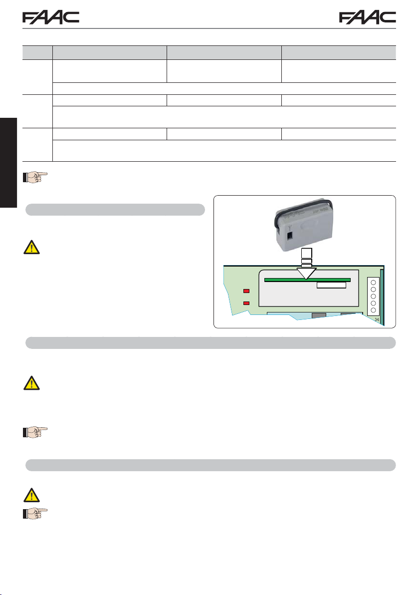
5.6.1 BUS 2easy DEVICE ENTRY
Access BASIC programming and scroll through the functions up until
1.
display will show the BUS 2easy devices status (see the figure).
2. Perform the entry: simultaneously press and hold
display will blink).
ENGLISH
will appear as a confirmation of entry completion.
3.
Y
4. Release the
devices according to the instructions of Chapter ELECTRICAL CONNECTIONS.
device entry.
. When F is released, the
bu
and - for at least 5 sec (during this time, the
and - buttons. The status of the BUS 2easy devices will be displayed.
If no BUS device has ever been entered in the board, the display will read
Opening photocells:
ON = entered and engaged
Encoder 1: ON = correctly connected
Opening photocells
and Closing photocells:
ON = entered and engaged
OPEN photocell:
ON = entered and engaged
Closing photocells:
ON = entered and engaged
Fig. Visualising the BUS 2easy status in the function
of device.
E145 30 732784 - Rev. B
bu
and entered
BUS Status: always ON
Encoder 2:
ON = correctly connected and
entered
: each segment of the display shows one type
no
.
Page 31

Fig. examples of BUS 2easy status visualization on display.
+
In STAND BY (gate closed and in stand-by) with
BUS 2easy Encoder on leaf 1 and leaf 2 and
BUS 2easy Photocells
entered.
In case of BUS 2easy Encoder on leaf1 and leaf 2
and BUS 2easy Photocells correctly connected and
entered and with closing photocells engaged:
correctly connected and
Checking the securing devices entered on the board
To verify the types of BUS device recognised through the entry:
1. Press and hold the
one entered device will go ON. E.g.:
To check the condition of the BUS 2easy connection, verify the LED on the board:
LED DL15 (Red)
ON Safety device engaged or pulse generator active
OFF NO safety device engaged neither pulse generator active
LED DL14 (Green)
ON steady Normal activity (led ON even if there are no devices).
Slow blinking (blink
every 2,5 sec)
Rapid blinking (blink
every 0.5 sec)
OFF Board in Sleep mode (if used).
button during stand-by visualisation; the segments corresponding to at least
at least one pair of opening
photocells correctly entered
Encoder on leaf 1 correctly
entered
+/
R1
Encoder on leaf 2 correctly
entered
at least one pair of closing
photocells correctly entered
BUS 2easy line short-circuit.
Error in the BUS 2easy connection.
Repeat the device entry
- That there are no more than one device in the system with the same
address.
- Calling error (number > or < the connected BUS devices).
SAFE error on the BUS device.
- FAIL
. If the error occurs again, check:
ENGLISH
E145 31 732784 - Rev. B
Page 32

5.4 TIME LEARNING - SETUP
+
-
+
FA
FA
01
FA
02
When the board is powered, if a SETUP has never been performed, or if the board requests it, on the
display
S0 indicates that a SETUP must be performed.
During SETUP, the connected BUS 2easy accessories are always entered.
The BUS 2easy encoders are to be enabled before SETUP: set the parameter En = Y (see
BASIC Programming)
For SETUP, proceed as follows:
During SETUP all safety devices are disabled! Therefore, carry out the operation avoiding
any transit in the leaf movement area.
ENGLISH
If a system without an encoder is installed, mechanical stops will be required for the leaves.
1. Enter BASIC programming and go to the parameter
2. Ensure that the gate leaves are closed. Otherwise, proceed as follows:
- Press and hold -/R2 to close leaf 2
- Press and hold +/R1 to close leaf 1
Should pressing +/R1 and/or -/R2 command opening of the corresponding leaf, cut off power
and, on terminal board J2, invert the phase cables of the corresponding motor (terminals 2-3
for leaf 1 motor and terminals 5-6 for leaf 2 motor).
3. With the gate leaves closed, launch SETUP by pressing and holding
on the display (about 3 sec).
4. Release
Stop movement by sending an OPEN A
pulse as soon as leaf 1 reaches the contact
point.
5. On the display
Stop movement by sending an OPEN A
pulse as soon as leaf 2 reaches the contact
point.
e -. Leaf 1 begins its opening movement.
Operation WITHOUT Encoder
will flash (only if 2 motors have been selected): leaf 2 begins opening.
S2
Operation WITHOUT Encoder
Steps 4 and 5 with function
=
FA
motion is ignored.
FA
after involving the opening limit switch.
(the limit switch determines the stopping of motion) the OPEN A pulse for stopping
01
=
(the limit switch determines the start of deceleration) send an OPEN A pulse only
02
FA
:
tL, when F is released ---- will appear.
and
Operation WITH Encoder
Leaf 1 will stop as soon as it reaches the
contact point. If there is no mechanical
stop, stop the leaf movement at the desired
point by sending an OPEN A pulse.
Operation WITH Encoder
Leaf 2 will stop as soon as it reaches the
contact point. If there is no mechanical
stop, stop the leaf movement at the desired
point by sending an OPEN A pulse.
until S1 begins to flash
E145 32 732784 - Rev. B
Page 33

6. On the display S3 will flash (only if 2 motors have been selected): leaf 2 begins closing.
FC
FC
01
FC
02
CF
Operation WITHOUT Encoder
Stop movement by sending an OPEN A
pulse as soon as leaf 2 reaches the contact
point.
7. On the display
Operation WITHOUT Encoder
Stop movement by sending an OPEN
A pulse as soon as leaf 1 reaches the
contact point.
Steps 6 and 7 with function
=
FC
01
motion is ignored.
=
FC
02
after involving the closing limit switch.
SET-UP for SLIDING LEAFS (
Steps 4, 5, 6 and 7 :
the leaf stop is determined by the limit switch. Any OPEN A impulses are ignored.
8. The board will automatically exit the programming menu and will display the automated system status
00) to confirm that the SETUP procedure has been completed correctly. If the procedure is not
(
completed correctly, on the display S0 will start flashing, indicating that a new SETUP procedure
must be performed.
The deceleration spaces can be configured and modified from the display using the parameters
flashes: leaf 1 begins closing.
S4
:
FC
(the limit switch determines the stopping of motion) the OPEN A pulse for stopping
(the limit switch determines the start of deceleration) send an OPEN A pulse only
02
)
CF= 02
Operation WITH Encoder
Leaf 2 will stop as soon as it reaches the
contact point. If there is no mechanical
stop, stop the leaf movement at the desired point by sending an OPEN A pulse.
Operation WITH Encoder
Leaf 1 will stop as soon as it reaches the
contact point. If there is no mechanical
stop, stop the leaf movement at the desired
point by sending an OPEN A pulse.
r1 and r2 (see Advanced Programming) without repeating the SETUP.
ENGLISH
5.5 TESTING THE AUTOMATED SYSTEM
Once installation and programming is completed, ensure that the system is operating correctly.
Be especially careful that the safety devices operate correctly and ensure that the system complies
with all current safety regulations. Close the cover in the provided seat with gasket.
E145 33 732784 - Rev. B
Page 34

OK
OK
MAX
5”
MAX
20 ”
6. MEMORISING THE RADIO CODE
The control board features an integrated 2-channel decoding system (DS, SLH/SLH LR, RC) called
OMNIDEC. This system lets you memorise, using an additional receiver module (on J5 connector)
and more radio controls having different technology but the same frequency.
both total opening (OPEN A) and partial opening (OPEN B).
The different types of radio code (DS, SLH/SLH LR, LC/RC) can coexist simultaneously
on the two channels. You can enter up to 1600 radio codes divided between OPEN A
and OPEN B/CLOSE.
T o use different encoding systems on the same channel, you must complete the learning of
each encoding system and then repeat the procedure for the other one.
, more detailed, programming options are available using a PC/MAC (see dedicated
Other
PC/MAC instructions). For example, you can set an automatic OPEN command on the radio
channel to command an automatic cycle (open-pause-close) regardless of the selected logic.
Keep the remote control at least 30 cm from the receiver.
ENGLISH
6.1 MEMORISING THE SLH/SLH LR RADIO CONTROLS
1. Press and hold +/R1 - SW1 (OPEN
• After keeping the button pressed for about 5 sec, the corresponding radio LED (DL11 or DL12)
will begin to flash slowly for about 20 sec.
2. Release the button.
3. Simultaneously press and hold P1 and P2 on the SLH/SLH LR radio control (only MASTER radio
control).
• The radio control LED will begin to flash.
4. Release both buttons.
Ensure that LED DL11 or DL12 on the board is still flashing (see point 2) and, while the radio con-
•
trol LED is still flashing, press and hold the desired button on the radio control (the radio control
LED will go on steady).
• The corresponding LED on the board (DL11 or DL12) will go on steady for 1 sec and then go off,
indicating that memorisation has been completed.
5. Release the radio control button.
6. To complete memorisation, press the button of the memorised radio control twice in succession.
• The automated system will perform an opening cycle.
Ensure that there are no obstacles (by people or things) during the automated system
movement.
A programming) or -/R2 - SW2 (OPEN B/CLOSE programming).
You can thus control
MAX
RX
> 30 cm
> 5”
+/
R1
DL11
RADIO 1
E145 34 732784 - Rev. B
TX
2”
P1 + P2
+/
R1
MAX
20”
5”
1”
OK
1”
OK
2 x 2”
Page 35

MAX
5”
OK
OK
OK
MAX
20 ”
MAX
20 ”
To enable other radio controls with the same system code, you must transfer the system code of
the memorised radio control button to the button corresponding to the radio control you wish to add:
1. Simultaneously press and hold P1 and P2 on the memorised radio control.
• The radio control LED will begin to flash.
2. Release both buttons.
3. Press and hold, while the radio control LED is still flashing, the memorised button (the radio control
LED will go on steady).
4. Bring the radio controls close together, press and hold the corresponding button of the radio control
you wish to add, and release only after the radio control LED flashes twice, indicating that memorisation has been completed.
5. Press the button of the memorised radio control twice in succession.
• The automated system will perform an opening cycle.
Ensure that there are no obstacles (by people or things) during the automated system
movement.
> 30 cm
TX
TX
MAX
5”
OK
+
x
2
2”
1”
DL11
RADIO 1
f, indicating that the procedure has been
OK
RX
> 30 cm
2”
P1 + P2
6.2 MEMORISING LC/RC RADIO CONTROLS (ONLY 433 MHZ)
1. Press and hold +/R1 - SW1 (OPEN A programming) or -/R2 - SW2 (OPEN B/CLOSE programming).
• After keeping the button pressed for about 5 sec, the corresponding radio LED (DL11 or DL12)
will begin to flash slowly for about 20 sec.
2. Release the button.
3. During radio LED flashing, press the desired button of the LC/RC radio control.
The corresponding LED on the board (DL11 or DL12) will go on steady for 1 second, indicating
•
that memorisation has been completed, and will begin flashing again for another 20 sec during
which you can memorise another radio control.
• When the 20 sec have elapsed, the LED will turn of
completed.
4. To add other radio controls, repeat the procedure from point 1.
RX
ENGLISH
> 5”
+/
R1
DL11
RADIO 1
E145 35 732784 - Rev. B
+/
R1
MAX
20”
1”
OK
MAX
20”
Page 36

OK
MAX
20 ”
6.2.1 REMOTE MEMORISATION OF LC/RC RADIO CONTROLS
With LC/RC radio controls you can remotely memorise other radio controls, i.e. without working directly
on the board, using a previously memorised radio control.
Take a radio control that has already been memorised on one of the 2 channels (OPEN
1.
B/CLOSE) and move to the vicinity of the board.
2. Simultaneously press and hold P1 and P2 until both LEDs flash slowly for 5 sec.
3. Within 5 seconds, press the previously memorised radio control button to activate the learning phase
for the selected channel.
4. The LED on the board corresponding to the channel in learning mode will flash for 20 sec within which
another radio control code is transmitted by pressing the button.
• The corresponding LED on the board will go on steady for 2 sec (indicating that memorisation has
been completed) and will begin flashing again for another 20 sec, during which you can memorise
other radio controls, and will finally go off.
6.3 MEMORISING DS RADIO CONTROLS
ENGLISH
the DS radio control, choose the desired ON - OFF combination of the 12 dip-switches.
1. On
2. Press and hold +/R1 - SW1 (OPEN
• After keeping the button pressed for about 5 sec, the corresponding radio LED (DL11 or DL12)
will begin to flash slowly for about 20 sec.
3. Release the button.
4. During radio LED flashing, press the button of the radio control you wish to program.
• The corresponding LED on the board (DL11 or DL12) will go on steady for 1 second and then go
off, indicating that memorisation has been completed.
5. To add other different codes, repeat the procedure starting from point 1.
6. To add other radio controls with the same code, set the 12 dip-switches according to the same combination as the already memorised radio control.
A programming) or -/R2 - SW2 (OPEN B/CLOSE programming).
A or OPEN
RX
> 30 cm
> 5”
+/
R1
DL11
RADIO 1
E145 36 732784 - Rev. B
TX
+/
R1
MAX
20”
1”
OK
Page 37

6.4 DELETING THE RADIO CONTROLS
This operation CANNOT be reversed. This will delete ALL the radio control codes memorised as both OPEN A and OPEN B/CLOSE. The cancellation procedure is active only
in gate status visualisation mode.
-/
R2
1. Press and hold -/R2
.
• After pressing for about 5 sec, the DL12 LED begins to flash slowly; after another 5 sec of slow
flashing and holding, the LEDs DL11 and DL12 begin flashing more rapidly (cancellation has started).
• Once rapid flashing has stopped, LEDs DL11 and DL12 will go on steady, confirming the cancellation
of all the radio codes (OPEN A and OPEN B/CLOSE) from the board memory.
2. Release -/R2
. The LEDs will go off, indicating correct cancellation.
-/R2
ENGLISH
E145 37 732784 - Rev. B
Page 38

RADIO XF 433-868
RADIO 1
DL12
DL11
RADIO 2
DL1
DL2
DL3
DL4
IC1
24V
DL14
DL6
DL5
DL10
TF1
J6
J10
FCC2 FCA2
FCC1 FCA1
J8
J5
BUS MON
.
+/R1
ERROR
SW3
SW1 SW2
IN5
DL13
DL17
DL16
USB
IN4
DL7
DL8
DL9
OC4
J9
BUS
F
5V
IN3
IN2
IN1
C52
F1
DB1
J2
FL1
J1
B
J4
9 10 11 12 13 14 15 16 17 18 19
20 21 22
26 25 24 23
PE N L
112131415161718
TOPCLOP
FSW
---
24V
+
+
LOCK
2
2
12 4567
COM
OP
COM
CL
LA
3
CL
1 2 3 4 5 6 7 8
PENL
TH2 TH1
RP/DEC
DL15
BAT1
CR2032
USB-BUSB-A
AC MAIN
M1
OP
M2
N3
IN4
IN5
8.8.
23
24
25
26
CONNECTIVITY
TF1
9 10 11 12 13 14 15 16 17 18 19
V
A
TH2
TH1
A
A
2
2
2
111
A1
A
3
23
A2
A2
5
4
4
868
1
2L11
2
5
1
NNE
NNENENENENENEEEENCTIVITYYYY
Y
1
0
7. START-UP
7.1 CHECKING THE LEDs
After having made all the connections and powered the board, check the status of the LEDs in relation
to the status of the inputs (the Figure shows the condition of closed automated system).
LED ON = contact closed LED OFF = contact open
ADIO
ADIO XF 433-
ADIO
L1
J
For the meaning
of the LEDs,
see “BOARD
LAYOUT”
ENGLISH
AT
For the meaning
of the LEDs, see
“BUS 2easy
DEVICE ENTR
PROCEDURE”
F
limit switches
OP - In default configuration, the STOP input is a safety input with contact N.C. (Normally Closed).
ST
The corresponding LED must be ON with the automated system at rest and go off when the connected
device is activated.
OPEN A, OPEN B - In default configuration, the OPEN A, OPEN B inputs are inputs with contact N.O.
(Normally Open). The corresponding LEDs must be OFF when the automated system is at rest, and
go ON when the connected device is in use.
Led ERROR - FLASHING = there is an alarm in progress (situation that does not compromise gate
operation) - see “ALARMS”. ON STEADY = there is an error in progress (situation that blocks operation
until the cause of the fault has been eliminated). See “ERRORS”.
with GATECODER
Flashing simultaneously during
movement of leaf 1. When the
leaf is stationary, they can both
be either on or off
Flashing simultaneously during
movement of leaf 2. When the
leaf is stationary
be either on or off
, they can both
LEDs FCA1, FCC1, FCA2, FCC2 - show the status of the limit switches N.C. contacts.
LED Name
DL4 FCA1 OPEN limit switch clear
DL3
ON
(closed contact)
FCC1 CLOSE limit switch clear
DL2 FCA2 OPEN limit switch clear
FCC2
DL1
E145 38 732784 - Rev. B
CLOSE limit switch clear
OFF
(open contact)
OPEN limit switch
engaged
CLOSE limit switch
engaged
OPEN limit switch
engaged
CLOSE limit switch
engaged
Y
Only if
are present
Page 39

8. SIGNALLING ERRORS AND ALARMS
+
-
+
In case of ERRORS (conditions that stop gate operation) or ALARMS (conditions that do not
compromise gate operation) the display will show the number corresponding to the warning in progress
by simultaneously pressing
These warnings will disappear in the following cycle only if the situation causing them is
removed.
8.1 ERRORS
When there is an ERROR the ERROR LED will go on steady. By simultaneously pressing
and - the display will show the corresponding error number.
The following table contains all the errors that can be viewed on the display.
and
.
N° ERROR SOLUTION
Board broken Replace the board
01
Invalid SETUP Repeat board SETUP
05
BUS 2easy device error Ensure that no two pairs of devices have the same address.
08
BUS 2easy output
09
short-circuit
Motor 2 limit switch error Check the limit switch connections for motor 1
10
Motor 2 limit switch error Check the limit switch connections for motor 1
11
BUS 2easy call
12
FAIL SAFE
13
Configuration error
14
Motor 1 encoder fault Check the connections or replace motor 1 encoder
17
Motor 2 encoder fault Check the connections or replace motor 2 encoder
18
Incorrect memory data Repeat BUS 2easy device entry and/or re-program the board
19
High absorption at +24V
93
Check the connections of the connected and entered
BUS 2easy devices
Ensure that the BUS devices are operating correctly and, if
necessary, repeat BUS device acquisition
Check that the safety devices (photocells) are operating correctly
Check that the board is configured correctly (basic and advanced
programming) and, if necessary, repeat SETUP
Check that absorption by the accessories connected is within
permitted limits
ENGLISH
E145 39 732784 - Rev. B
Page 40

8.2 ALARMS
When there is an ALARM the ERROR LED will begin to flash. By simultaneously pressing +
and - the display will show the corresponding alarm number.
The following table contains all the alarms that can be viewed on the display.
N° ALARM Solution/Description
20
21
25
26
ENGLISH
27
28
30
31
35
40
50
60
62
63
64
Obstacle on MOTOR 1 (only with
encoder)
Obstacle on MOTOR 2 (only with
encoder)
LOCK 1 output short-circuit Remove the cause of the short-circuit
LOCK 2 output short-circuit Remove the cause of the short-circuit
Nr. of consecutive obstacles
exceeded during opening
Nr. of consecutive obstacles
exceeded during closing
XF radio code memory full
Breach alarm
TIMER active and TIMER function
operating:
Service request Contact the installer for maintenance
The HOLD POSITION is operating
(active on PC/MAC )
TIMER active and error in TIMER
data
Loss of time and date on the board
(only if the TIMER is operating)
JOLLY TIMER is activated JOLLY TIMER is enabled by terminal board J3
TIMER DISABLED is operating TIMER is disabled by terminal board J3
Remove any possible obstacle on leaf 1
Remove any possible obstacle on leaf 2
Remove any possible obstacle.
Should the problem persist, repeat SETUP
Remove any possible obstacle.
Should the problem persist, repeat SETUP
Cancel the radio codes that are not being used using
the PC program or use an additional DEC/MINIDEC/
RP module
A movement was made with the automated system in
status St = 00 or 01.
Perform an operation cycle.
TIMER function is operating
HOLD POSITION function is operating
Reload a correct TIMER configuration with the PC/MAC
programme
Reload the time and date with the PC/MAC programme
and replace the BAT1 - CR2032 buffer battery
E145 40 732784 - Rev. B
Page 41

9. TROUBLESHOOTING
Description Solution
A
The board does not turn on
The gate will not open after
B
an OPEN pulse
The gate does not reverse
C
when the photocells are
engaged
The gate does not reverse
D
when encountering an
obstacle
E
The gate will not close
• Ensure that the board is receiving the 230V~
• Ensure that fuse F1 is intact
• Check that the safety devices and STOP are connected
to the negative and ensure that the corresponding LEDs
are ON
• Check the photocells (alignment, engagement)
• Check that the SETUP has been completed correctly.
Repeat if necessary
• Check that the traditional photocells are correctly wired and
that the BUS photocell configuration is correct (if present).
If necessary, repeat the acquisition of the BUS 2easy
devices
•
Ensure that the encoders on motors are enabled
• Check the obstacle detection sensitivity
• Check that the photocell wiring and alignment is correct
• Check that there is no OPEN signal active
• Check which function logic has been chosen (automatic
or semi-automatic)
ENGLISH
E145 41 732784 - Rev. B
Page 42

10. MANAGING THE CONFIGURATION FILE – J8 USB
Using the J8 USB connector you can both transfer to the board the configuration and management files
from a USB drive and copy the same files stored on the board to the USB memory. When transferring
from the USB memory to the board, the files must be located in the memory root, as shown in the
screenshot below:
In addition, the names and extensions of the various files must be as follows:
cod
ENGLISH
• E145SW.cod - The board SOFTWARE update file
• E145.trm - The board TIMER update file
• E145.prg - The board PROGRAMMING update file
• E145.rad - The board RADIO update file
These files will be generated, named and placed as shown in fig. in case of transfer from the board to the
USB memory.
If at board power up a USB memory is detected inserted in the board J8 connector, after displaying the
writing bo, it will be possible to access the update file management menu (see the following table)
(press F for scrolling through the functions) :
The SOFTWARE update file must be downloaded from the FAACwebsite according to the version of the board. The
-
filename must not be changed. For boards previous to version 1R, the filename has a .bin extension; for version 1R
boards or later, the filename has a .cod extension.
- The file will transferred from the USB memory key to the board only if it has been saved in the root directory of the
USB memory key and is not compressed.
Display Function
US
BOARD SOFTWARE UPGRADE:
This function lets you update the board application (file E145SW.cod).
If + and - are pressed simultaneously for at least 5 seconds, you will access
the board update. The writing
no will disappear and, in its place, the writing
-- and the USB DL10 LED will begin flashing.
Once updating is completed,
otherwise the writing
The upgrade is carried out correctly only if the USB
memory contains a valid file named exactly E145SW.cod
E145 42 732784 - Rev. B
Y will be displayed if it has been done correctly,
no will appear again.
Default
--
Page 43

Display Function
Uc
BOARD CONFIGURATION UPGRADE:
This function lets you transfer the configuration to the board (file E145.prg).
If + and - are pressed simultaneously for at least 5 seconds, you will access the
board configuration update. The writing
the writing
Once updating is completed,
otherwise the writing
The upgrade is carried out correctly only if the USB memory
Default
--
no will disappear and, in its place,
-- and the USB DL10 LED will begin flashing.
Y will be displayed if it has been done correctly,
no will appear again.
contains a valid file named exactly E145.prg
ENGLISH
Ut
Ur
TIMER CONFIGURATION UPGRADE:
This function lets you update the timer configuration on the board (file
E145.trm).
If + and - are pressed simultaneously for at least 5 seconds, you will access
the board update. The writing no will disappear and, in its place, the writing
-- and the USB DL10 LED will begin flashing.
Once updating is completed,
otherwise the writing
The upgrade is carried out correctly only if the USB memory
contains a valid file named exactly E145.trm
RADIO CODE LIST UPGRADE:
This function lets you update the radio code list on the board (file E145.rad).
If + and - are pressed simultaneously for at least 5 seconds, you will access
the board update. The writing
Y will be displayed if it has been done correctly,
no will appear again.
no will disappear and, in its place, the writing
-- and the USB DL10 LED will begin flashing.
Once updating is completed
otherwise the writing
The upgrade is carried out correctly only if the USB memory
contains a valid file named exactly E145.rad
Y will be displayed if it has been done correctly,
no will appear again.
--
--
E145 43 732784 - Rev. B
Page 44

Display Function
dc
ENGLISH
BOARD CONFIGURATION DOWNLOAD:
This function lets you save the board configuration in the USB memory in
order to store (parameter
(parameter
If + and – are pressed simultaneously for at least 5 seconds, the following
selection values will appear:
00).
01) or copy the configuration to other systems
01 = Storage: the configuration file will be saved in the format E145_xxx.prg
where xxx=000/001/002 etc. depending on how many configuration files there
are in the USB memory.
00 = Copy: the configuration file will be saved in the format E145.prg by
overwriting any other configuration file present with the same name, so it can
be used to upgrade another system.
Press + and - to select the desired parameter and, by pressing F
will proceed to save the file and display
of errors during saving.
Y when done correctly, or no in case
, the board
Default
--
dt
dr
BOARD TIMER DOWNLOAD:
This function lets you save the board Timer configuration in the USB memory in
order to store (parameter
(parameter
If + and - are pressed simultaneously for at least 5 seconds, the following
selection values will appear:
00).
01) or copy the Timer configuration to other systems
01 = Storage: the Timer configuration file will be saved in the format E145_xxx.
trm where xxx=000/001/002 etc. depending on how many Timer configuration
files there are in the USB memory.
00 = Copy: the Timer configuration file will be saved in the format
E145.trm by overwriting any other Timer configuration file present with the
same name, so it can be used to upgrade another system.
Press + and - to select the desired parameter and, by pressing F
will proceed to save the file and display
of errors during saving.
BOARD RADIO CODE DOWNLOAD:
This function lets you save in the USB memory the board radio codes in order to
store (parameter
If + and - are pressed simultaneously for at least 5 seconds, the following
selection values will appear:
01) or copy the radio codes to other systems (parameter 00).
Y when done correctly, or no in case
, the board
01 = Storage: the radio codes file will be saved in the format E145_xxx.rad
where xxx=000/001/002 etc. depending on how many radio codes files there
are in the USB memory.
00 = Copy: the radio codes file will be saved in the format E145.rad by
overwriting any other radio codes file present with the same name, so it can
be used to upgrade another system.
Press + and - to select the desired parameter and, by pressing F
will proceed to save the file and display
of errors during saving.
Y when done correctly, or no in case
, the board
--
--
E145 44 732784 - Rev. B
Page 45

11. FUNCTION LOGICS
This table summarizes the function logics.
For a detailed description of each one, see the queued Tables.
LOGIC
E
Semiautomatic
EP
Semiautomatic,
Step-by-Step
S
Automatic
Safety
SA
Automatic
Safety
reversing
during pause
Automated system
status: stopped
An OPEN pulse opens
the gate and the
following one will close it
An OPEN pulse opens
the gate and the
following one will close it
An OPEN pulse opens
the gate and closes
automatically after the
pause time
An OPEN pulse opens
the gate and closes
automatically after the
pause time
Automated system
status: in motion
An OPEN pulse while
opening stops and
reopens during closing
An OPEN pulse during
motion blocks
An OPEN pulse during
pause closes and
reverses during motion
An OPEN pulse during
pause closes; during
opening it has no effect;
it reverses during
closing
Status: photocell
involvement
During motion, the
photocells reverse
During motion, the
photocells reverse
The closing photocells
reclose the gate during
pause; they memorise
closing during opening
and immediately
reverse during closing
The closing photocells
reset the pause time
ENGLISH
SP
Automatic
Safety
Step-by-Step
A1
Automatic 1 An OPEN pulse opens
E145 45 732784 - Rev. B
An OPEN pulse opens
the gate and closes
automatically after the
pause time
the gate and closes
automatically after the
pause time
An OPEN pulse during
pause closes and
during motion blocks
the operation
An OPEN pulse
during opening is
ignored, during pause
it recharges the pause
time and during closing
it reopens the leaves
The closing photocells
reclose the gate during
pause; they memorise
closing during opening
and immediately
reverse during closing
The closing photocells
reclose the gate during
pause; they memorise
closing during opening
and immediately
reverse during closing
Page 46

A
Automatic An OPEN pulse opens
the gate and closes
automatically after the
pause time
AP
Automatic
Step-by-Step
An OPEN pulse opens
the gate and closes
automatically after the
pause time
ENGLISH
At
Automatic
Timer
An OPEN pulse opens
the gate and closes
automatically after
the pause time. If the
cycle started with an
OPEN input, it opens,
otherwise it closes
An OPEN pulse
during opening is
ignored, during pause
it recharges the pause
time and during closing
it reopens the leaves
An OPEN pulse during
opening and during
pause blocks the
operation; it reverses
during closing
An OPEN pulse during
opening is ignored,
during pause it resets
the pause time and
during closing it reopens
the leaves
The closing photocells
recharge the pause time
The closing photocells
recharge the pause time
The closing photocells
recharge the pause time
b Semiautomatic
“b” (OPEN-B
inputs become
CLOSE)
bC Mixed
Logic (during
opening “b”,
during closing
Logic with two separate
commands: OPEN-A
pulse opens; CLOSE
pulse closes
Logic with two separate
commands: OPEN-A
pulse opens; a held
CLOSE pulse closes
An OPEN-A pulse
during closing opens,
a CLOSE pulse during
opening closes
An OPEN-A pulse
during closing opens,
a CLOSE pulse during
opening closes
During motion, the
photocells reverse
During motion, the
photocells reverse
“C”), (OPEN-B
inputs become
CLOSE)
C Dead-man
(OPEN-B
inputs become
CLOSE)
Logic with two separate
commands: a held
OPEN-A pulse opens;
a held CLOSE pulse
An OPEN-A pulse
during closing opens,
a CLOSE pulse during
opening closes
During motion, the
photocells reverse
closes
E145 46 732784 - Rev. B
Page 47

EP
E
SEMI-AUTOMATIC LOGIC
PULSES
AUTOMATED
SYSTEM
STA TUS
CLOSED OPENS
OPENING
OPEN
CLOSING OPENS NO EFFECT STOPS* NO EFFECT
*
STOPPED CLOSES
A OPEN B CLOSE STOP FSW OP FSW CL FSW CL/OP
OPEN
STOPS
CLOSES
*
OPENS
PARTIALLY
1
STOPS* CLOSES STOPS* REVERSES NO EFFECT
1
EFFECT NO EFFECT (OPEN DISABLED) NO EFFECT
NO
EFFECT
NO
CLOSES
(
OPEN/CLOSE
DISABLED)
EFFECT
NO
(
OPEN/CLOSE
DISABLED)
NO EFFECT
NO EFFECT
(
OPEN
DISABLED)
EFFECT
NO
(
CLOSE
DISABLED)
REVERSES
NO EFFECT
(
CLOSE
DISABLED)
EFFECT (OPEN
NO
STOPS
(
OPEN STOPS* -
SAVES CLOSE)
NO EFFECT (OPEN/
CLOSE DISABLED)
STOPS; OPENS
AT RELEASE
2
(
OPEN STOPS* -
SAVES CLOSE)
(
OPEN STOPS* -
SAVES CLOSE)
DISABLED)
; OPENS AT
RELEASE
ENGLISH
NO EFFECT
EP
AUTOMATED
SYSTEM
STA TUS
CLOSED OPENS
OPENING
OPEN
CLOSING STOPS* NO EFFECT STOPS* NO EFFECT
*
STOPPED
SEMI-AUTOMATIC “STEP-BY-STEP” LOGIC
A OPEN B CLOSE STOP FSW OP FSW CL FSW CL/OP
OPEN
OPENS
PARTIALLY
1
*
STOPS
CLOSES
RESTARTS
OPPOSITE
ALWAYS CLOSES AFTER STOP
STOPS* CLOSES STOPS* REVERSES NO EFFECT
1
MOVING IN THE
DIRECTION.
3
it opens if, at power up, an OPEN (A or B) command is active. Otherwise it closes.
EFFECT NO EFFECT (OPEN DISABLED) NO EFFECT
NO
EFFECT
NO
CLOSES
CLOSES
(
OPEN/CLOSE
DISABLED)
EFFECT
NO
(
OPEN/CLOSE
DISABLED)
PULSES
EFFECT
NO
(
OPEN DISABLED)
STOPS
; OPENS AT
RELEASE
(
OPEN STOPS* -
SAVES CLOSE)
EFFECT
NO
NO EFFECT
NO EFFECT
(
OPEN
DISABLED)
1
if the cycle began with OPEN-B, opens totally
2
operation can be modified by programming
(
CLOSE
DISABLED)
REVERSES
NO EFFECT
(
CLOSE
DISABLED)
NO EFFECT (OPEN/
CLOSE DISABLED)
STOPS; OPENS AT
2
RELEASE (OPEN STOPS*
-
SAVES CLOSE)
NO EFFECT
(
OPEN STOPS* -
SAVES CLOSE)
E145 47 732784 - Rev. B
Page 48

S
AUTOMATIC “SAFETY” LOGIC
SA
PULSES
AUTOMATED
SYSTEM
STA TUS
CLOSED
OPENING REVERSES CLOSES STOPS* REVERSES
OPEN IN PAUSE
A OPEN B CLOSE STOP FSW OP FSW CL FSW CL/OP
OPEN
OPENS
;
OPENS
CLOSES AFTER
PAUSE
CLOSES
TIME
PARTIALLY
CLOSES AFTER
PAUSE
1
;
NO
EFFECT NO EFFECT (OPEN DISABLED) NO EFFECT
TIME
CLOSES STOPS* NO EFFECT
ENGLISH
CLOSING OPENS NO
*STOPPED CLOSES
EFFECT STOPS* NO EFFECT
EFFECT
NO
(
OPEN/CLOSE
DISABLED)
NO EFFECT
(
OPEN
DISABLED)
COMPLETES
OPENING
CLOSES WITHOUT
REVERSES
WITHOUT
(
CLOSE DISABLED)
THE
, THEN
TIME
PAUSE
CLOSES AT RELEASE
THEN CLOSES
PAUSE
TIME
NO EFFECT
NO
(
OPEN DISABLED)
STOPS
OPENS AT RELEASE
(SAVES CLOSE)
;
STOPS
;
OPENS AT
RELEASE
CLOSES WITHOUT
PAUSE
NO EFFECT
(
OPEN/CLOSE
DISABLED)
STOPS
2
EFFECT
;
;
, THEN
TIME
SA
AUTOMATED
SYSTEM
STA TUS
CLOSED
OPENING
OPEN IN PAUSE
CLOSING OPENS NO EFFECT STOPS* NO EFFECT
*
STOPPED CLOSES
AUTOMATIC “SAFETY” WITH IN-PAUSE REVERSING LOGIC
PULSES
A OPEN B CLOSE STOP FSW OP FSW CL FSW CL/OP
OPEN
OPENS
;
OPENS
CLOSES AFTER
PAUSE
EFFECT
NO
CLOSES
PARTIALLY
;
NO
CLOSES AFTER
TIME
1
3
it opens if, at power up, an OPEN (A or B) command is active. Otherwise it closes.
TIME
PAUSE
1
NO EFFECT CLOSES STOPS* REVERSES NO EFFECT
EFFECT NO EFFECT (OPEN DISABLED) NO EFFECT
CLOSES STOPS* NO EFFECT
EFFECT
NO
(
OPEN/CLOSE
DISABLED)
NO EFFECT
(
OPEN
DISABLED)
1
if the cycle began with OPEN-B, opens totally
2
operation can be modified by programming
RECHARGES
PAUSE
TIME (CLOSE DISABLED)
REVERSES
NO EFFECT
(
CLOSE
DISABLED)
EFFECT (OPEN
NO
DISABLED)
STOPS
(
SAVES CLOSE)
STOPS; OPENS
2
AT RELEASE
(
SAVES CLOSE)
NO EFFECT
(
OPEN/CLOSE
DISABLED)
RELEASE
E145 48 732784 - Rev. B
; OPENS AT
Page 49

SP
SP
A1
AUTOMATED
SYSTEM
STA TUS
CLOSED
OPENING
OPEN IN PAUSE
CLOSING STOPS
*
STOPPED
AUTOMATIC “SAFETY” “STEP-BY-STEP” LOGIC
A OPEN B CLOSE STOP FSW OP FSW CL FSW CL/OP
OPEN
OPENS
CLOSES AFTER
TIME
PAUSE
*
STOPS
CLOSES
RESTARTS
OPPOSITE
ALWAYS CLOSES AFTER STOP
OPENS
;
PARTIALLY
;
NO
EFFECT NO EFFECT (OPEN DISABLED) NO EFFECT
CLOSES STOPS* NO EFFECT
1
1
CLOSES AFTER
TIME
PAUSE
STOPS* CLOSES STOPS* REVERSES
* NO EFFECT STOPS* NO EFFECT
MOVING IN THE
DIRECTION.
CLOSES
EFFECT
NO
(
OPEN/CLOSE
DISABLED)
PULSES
NO EFFECT
(
OPEN
DISABLED)
COMPLETES
THE
OPENING,
THEN CLOSES
WITHOUT
TIME
PAUSE
CLOSES AT RELEASE
REVERSES
NO EFFECT
(
CLOSE
DISABLED)
EFFECT (OPEN
NO
DISABLED)
; OPENS AT
STOPS
RELEASE, THEN CLOSES
WITHOUT PAUSE TIME
(
OPEN STOPS* - SAVES
CLOSE)
;
STOPS
STOPS; OPENS
2
AT RELEASE
(
SAVES CLOSE)
NO EFFECT (OPEN/
CLOSE DISABLED)
ENGLISH
A1
AUTOMATED
SYSTEM
STA TUS
CLOSED
OPENING
OPEN
CLOSING OPENS NO
*STOPPED CLOSES
AUTOMATIC1 LOGIC
OPEN
OPENS
CLOSES AFTER
PAUSE
EFFECT
NO
IN PAUSE
RECHARGES
PAUSE
PULSES
A OPEN B CLOSE ST OP FSW OP FSW CL FSW CL/OP
OPENS
;
PARTIALLY
;
NO
TIME
TIME
CLOSES AFTER
PAUSE
1
NO EFFECT CLOSES STOPS*
RECHARGES
1
PAUSE
TIME
TIME
EFFECT
CLOSES STOPS
EFFECT STOPS* NO EFFECT
(
3
it opens if, at power up, an OPEN (A or B) command is active. Otherwise it closes.
EFFECT
NO
(OPEN DISABLED)
* NO EFFECT
NO
EFFECT
OPEN/CLOSE
DISABLED)
NO EFFECT
COMPLETES
OPENING,
THE
2
NO EFFECT
(
OPEN
DISABLED)
1
if the cycle began with OPEN-B, opens totally
2
operation can be modified by programming
THEN CLOSES
WITHOUT
TIME
DISABLES
AT RELEASE
CLOSES
REVERSES
NO EFFECT
(
CLOSE
DISABLED)
PAUSE
CLOSE;
NO
(
OPEN DISABLED)
STOPS
RELEASE, THEN CLOSES
WITHOUT PAUSE TIME
THE END OF THE
AT
TIME, CLOSES AT
PAUSE
RELEASE
STOPS; OPENS AT
RELEASE, THEN CLOSES
2
AFTER
PAUSE
NO EFFECT
(
OPEN/CLOSE DISABLED)
EFFECT
; OPENS AT
E145 49 732784 - Rev. B
TIME
Page 50

AP
A
AUTOMATIC LOGIC
PULSES
AUTOMATED
SYSTEM
STA TUS
CLOSED
OPENING
OPEN IN PAUSE
ENGLISH
CLOSING OPENS NO EFFECT STOPS* NO EFFECT
*
STOPPED CLOSES
A OPEN B CLOSE STOP FSW OP FSW CL FSW CL/OP
OPEN
OPENS
;
OPENS
CLOSES AFTER
PAUSE
EFFECT
NO
RECHARGES
PAUSE
TIME
PARTIALLY
;
NO
CLOSES AFTER
TIME
1
TIME
PAUSE
1
NO EFFECT CLOSES STOPS* REVERSES NO EFFECT
RECHARGES
TIME
PAUSE
EFFECT NO EFFECT (OPEN DISABLED) NO EFFECT
CLOSES STOPS
* NO EFFECT
EFFECT
NO
(
OPEN/CLOSE
DISABLED)
NO EFFECT
(
OPEN
DISABLED)
RECHARGES
PAUSE
TIME (CLOSE DISABLED)
REVERSES
NO EFFECT
(
CLOSE
DISABLED)
EFFECT
NO
(
OPEN DISABLED)
STOPS
; OPENS AT
RELEASE
(
SAVES CLOSE)
STOPS; OPENS
2
AT RELEASE
(
SAVES CLOSE)
NO EFFECT (OPEN/
CLOSE DISABLED)
AP
AUTOMATED
SYSTEM
STA TUS
CLOSED
OPENING
OPEN IN PAUSE
CLOSING OPENS NO EFFECT STOPS* NO EFFECT
*
STOPPED CLOSES
AUTOMATIC “STEP-BY-STEP” LOGIC
A OPEN B CLOSE STOP FSW OP FSW CL FSW CL/OP
OPEN
OPENS
;
OPENS
CLOSES AFTER
PAUSE
STOPS
STOPS
PARTIALLY
;
NO
CLOSES AFTER
TIME
1
*
1
*
3
it opens if, at power up, an OPEN (A or B) command is active. Otherwise it closes.
TIME
PAUSE
STOPS* CLOSES STOPS*
STOPS* CLOSES STOPS* NO EFFECT
EFFECT NO EFFECT (OPEN DISABLED) NO EFFECT
PULSES
REVERSES
(
SAVES OPEN)
EFFECT
NO
(
OPEN/CLOSE
DISABLED)
NO EFFECT
(
OPEN
DISABLED)
1
if the cycle began with OPEN-B, opens totally
2
operation can be modified by programming
NO EFFECT
PAUSE
TIME (CLOSE DISABLED)
REVERSES
NO EFFECT
(
CLOSE
DISABLED)
RECHARGES
2
RELEASE
EFFECT (OPEN
NO
DISABLED)
STOPS
; OPENS AT
RELEASE
(
OPEN STOPS* -
SAVES CLOSE)
STOPS;
(OPEN STOPS*
-
SAVES CLOSE)
NO EFFECT (OPEN/
CLOSE DISABLED)
E145 50 732784 - Rev. B
OPENS AT
Page 51

b
At
AUTOMATED
SYSTEM
STA TUS
CLOSED
OPENING
OPEN IN PAUSE
CLOSING OPENS NO EFFECT STOPS* NO EFFECT
*
STOPPED CLOSES
AUTOMATED
SYSTEM
STA TUS
CLOSED OPENS NO
OPENING NO EFFECT CLOSES STOPS* REVERSES NO EFFECT
OPEN NO EFFECT CLOSES
CLOSING OPENS NO EFFECT STOPS* NO EFFECT
*
STOPPED OPENS CLOSES
AUTOMATIC WITH TIMER FUNCTION LOGIC
PULSES
OPEN
A OPEN B CLOSE STOP FSW OP FSW CL FSW CL/OP
OPENS
;
OPENS
CLOSES AFTER
PAUSE
EFFECT
NO
RECHARGES
PAUSE
TIME
SEMI-AUTOMATIC “B” LOGIC (OPEN-B INPUTS BECOME CLOSE)
OPEN
PARTIALLY
;
NO
CLOSES AFTER
TIME
1
TIME
PAUSE
1
NO EFFECT CLOSES STOPS* REVERSES NO EFFECT
RECHARGES
TIME
PAUSE
EFFECT
CLOSES STOPS
EFFECT
NO
(
OPEN/CLOSE
DISABLED)
PULSES
A OPEN B CLOSE STOP FSW OP FSW CL FSW CL/OP
EFFECT
(OPEN DISABLED)
EFFECT
NO
(
OPEN/CLOSE
DISABLED)
EFFECT
NO
(
OPEN/CLOSE
DISABLED)
NO
3
EFFECT
NO
(OPEN DISABLED)
* NO EFFECT
NO EFFECT
(
OPEN
DISABLED)
EFFECT
NO EFFECT
NO EFFECT
(
OPEN
DISABLED)
REVERSES
NO EFFECT
NO
(
DISABLED)
REVERSES
NO EFFECT
(
DISABLED)
NO EFFECT
RECHARGES
(CLOSE DISABLED)
NO EFFECT
(
CLOSE
DISABLED)
EFFECT
CLOSE
CLOSE
NO
(
OPEN DISABLED)
STOPS
AT RELEASE
(
SAVES CLOSE)
PAUSE TIME
STOPS; OPENS
2
AT RELEASE
(
SAVES CLOSE)
NO EFFECT (OPEN/
CLOSE DISABLED)
EFFECT (OPEN
NO
DISABLED)
; CLOSES AT
STOPS
RELEASE
(
SAVES OPEN/CLOSE)
NO EFFECT (OPEN/
CLOSE DISABLED)
STOPS; OPENS AT
2
RELEASE (SAVES
OPEN/CLOSE)
NO EFFECT (OPEN/
CLOSE DISABLED)
EFFECT
; OPENS
ENGLISH
1
if the cycle began with OPEN-B, opens totally
2
operation can be modified by programming
3
it opens if, at power up, an OPEN (A or B) command is active. Otherwise it closes.
E145 51 732784 - Rev. B
Page 52

bC
C
AUTOMATED
SYSTEM
STA TUS
CLOSED OPENS NO
OPENING NO EFFECT CLOSES STOPS* REVERSES NO EFFECT
OPEN NO EFFECT CLOSES
ENGLISH
CLOSING OPENS NO EFFECT STOPS* NO EFFECT
*
STOPPED OPENS CLOSES
AUTOMATED
SYSTEM
STA TUS
CLOSED OPENS NO
OPENING NO EFFECT CLOSES STOPS* REVERSES NO EFFECT
OPEN NO EFFECT CLOSES
CLOSING OPENS NO EFFECT STOPS* NO EFFECT
*
STOPPED OPENS CLOSES
MIXED LOGIC: B IN OPENING - C IN CLOSING (OPEN-B INPUTS BECOME CLOSE)
PULSES FOR OPENING / DEAD-MAN
COMMANDS FOR CLOSING
A OPEN B CLOSE STOP FSW OP FSW CL FSW CL/OP
OPEN
EFFECT
EFFECT
DEAD-MAN LOGIC (OPEN-B INPUTS BECOME CLOSE)
DEAD-MAN COMMANDS PULSES
A OPEN B CLOSE STOP FSW OP FSW CL FSW CL/OP
OPEN
EFFECT
NO
(OPEN DISABLED)
EFFECT
NO
(
OPEN/CLOSE
DISABLED)
EFFECT
NO
(
OPEN/CLOSE
DISABLED)
(OPEN DISABLED)
EFFECT
NO
(
OPEN/CLOSE
DISABLED)
EFFECT
NO
(
OPEN/CLOSE
DISABLED)
NO
NO EFFECT
NO EFFECT
DISABLED)
EFFECT
NO EFFECT
NO EFFECT
(
OPEN
(
OPEN
DISABLED)
PULSES
NO EFFECT
EFFECT
NO
(
CLOSE
DISABLED)
REVERSES
NO EFFECT
(
CLOSE
DISABLED)
NO EFFECT
NO
(
DISABLED)
REVERSES
NO EFFECT
(
DISABLED)
EFFECT
CLOSE
CLOSE
EFFECT (OPEN
NO
STOPS
(
SAVES OPEN/CLOSE)
NO EFFECT (OPEN/
CLOSE DISABLED)
STOPS; OPENS AT
2
RELEASE (SAVES
OPEN/CLOSE)
NO EFFECT (OPEN/
CLOSE DISABLED)
(
OPEN DISABLED)
STOPS
(
SAVES OPEN/CLOSE)
NO EFFECT (OPEN/
CLOSE DISABLED)
STOPS; OPENS AT
2
RELEASE (SAVES
OPEN/CLOSE)
NO EFFECT (OPEN/
CLOSE DISABLED)
DISABLED)
; CLOSES AT
RELEASE
EFFECT
NO
; CLOSES AT
RELEASE
1
if the cycle began with OPEN-B, opens totally
2
operation can be modified by programming
3
it opens if, at power up, an OPEN (A or B) command is active. Otherwise it closes.
E145 52 732784 - Rev. B
Page 53

FAAC S.p.A. Soc. Unipersonale
Via Calari, 10 - 40069 Zola Predosa BOLOGNA - ITALY
Tel. +39 051 61724 - Fax +39 051 758518
www.faac.it - www.faacgroup.com
732784 - Rev. B
 Loading...