

Page 1
E124
E124
Page 2

Page 3

INDEX
1 LAY-OUT OF ELECTRICAL BOX ........................................................................................ 2
2 WARNINGS ................................................................................................................... 4
3 LAYOUT AND COMPONENTS OF E124 ...........................................................................4
3.1 INPUTS DEFAULT SETTING ............................................................................................ 4
3.2 DESCRIPTION OF COMPONENTS ............................................................................... 5
4 TECHNICAL SPECIFICATIONS ......................................................................................... 5
5 TERMINAL BOARDS, CONNECTORS, INPUTS AND SIGNALS ............................................ 6
5.1 TERMINAL BOARD J3 – CONNECTION TO BUS-2EASY ACCESSORIES ........................6
5.2 TERMINAL BOARD J4 – SIGNALS INPUTS .................................................................... 6
5.3 TERMINAL BOARDS J5, J8 – OUT1 AND OUT2 ............................................................ 6
5.4 TERMINAL BOARD J6 – OPENING AND CLOSING TRAVEL LIMIT DEVICE ...................... 7
5.5 TERMINAL BOARDS J7 - ENCODERS ..........................................................................7
5.6 TERMINAL BOARD J9 – FLASHING LAMP .................................................................... 7
5.7 TERMINAL BOARD J10 – ELECTRIC LOCK ................................................................... 7
5.8 TERMINAL BOARD J11, J12 - MOTORS ...................................................................... 7
5.9 CONNECTOR J1 - PRIMARY POWER FEED FROM 230/115 V MAINS .......................... 7
5.10 CONNECTOR J2 - SECONDARY POWER FEED ............................................................ 8
5.11 Connector J13 – XF MODULE rapid connection ...................................................... 8
5.12 CONNECTOR J14- FOR RAPID CONNECTION OF MINIDEC, DECODER AND RP ......... 8
5.13 Connector M1A – Rapid connection MODULE X-COM ............................................ 8
6 ELECTRICAL CONNECTIONS .......................................................................................... 9
6.1 TRADITIONAL PHOTOCELLS ........................................................................................ 9
6.2 PHOTOCELLS BUS-2EASY ...........................................................................................11
6.2.1 ADDRESSING THE BUS-2EASY PHOTOCELLS ........................................................ 11
6.2.2 MEMORY STORAGE OF BUS-2EASY ACCESSORIES ...............................................12
6.2.3 ADDRESSING THE BUS-2EASY ENCODERS ............................................................ 12
7. PROGRAMMING ............................................................................................................ 13
7.1. 1
7.2. 2
7.3. PROGRAMMING FROM PC (3
8 SAVING THE RADIO CODE .............................................................................................22
8.1 SAVING DS RADIO CONTROLS ..................................................................................22
8.2 SAVING SLH RADIO CONTROLS ................................................................................. 22
8.3 MEMORY STORAGE OF THE LC/RC RADIO CONTROLS (FOR SOME MARKETS ONLY) .. 23
8.4 RADIO CONTROLS DELETION PROCEDURE ...............................................................23
9 CONNECTION TO EMERGENCY BATTERIES (OPTIONAL) ................................................. 23
10 START-UP ....................................................................................................................... 24
10.1 LEDS CHECK ............................................................................................................. 24
10.2 TIME LEARNING - SETUP ............................................................................................. 25
11 AUTOMATED SYSTEM TEST ............................................................................................. 25
12 ALARM AND ERROR SIGNALS ........................................................................................ 25
12.1 ALARMS .................................................................................................................... 25
12.2 ERRORS ....................................................................................................................25
13 FUNCTION LOGICS ........................................................................................................ 26
ST
LEVEL PROGRAMMING ........................................................................................ 13
nd
LEVEL PROGRAMMING .......................................................................................16
8.3.1 REMOTE SAVING OF LC/RC RADIO CONTROLS .................................................... 23
rd
LEVEL) ....................................................................... 22
ENGLISH
CE DECLARATION OF CONFORMITY
Manufacturer: FAAC S.p.A.
Address: Via Calari, 10 - 40069 Zola Predosa BOLOGNA - ITALY
Declares that: The E124 control unit
2006/95/EC Low Voltage Directive
2004/108/EC Electromagnetic Compatibility Directive
Additional note:
This product underwent tests in a typical uniform configuration
(all products manufactured by FAAC S.p.A.).
The Managing Director
A.Marcellan
• Important! For the safety of people, it is important that all the instructions be carefully observed.
• Incorrect installation or incorrect use of the product could cause serious harm to people.
• Carefully read the instructions before beginning to install the product and keep them for future reference.
•
The symbol indicates notes that are important for the safety of persons and for the good condition of the automated system.
• The symbol draws your attention to the notes on the characteristics and operation of the product.
• ·conforms to the essential safety requirements of the following EEC directives
Bologna, 01 - 01 - 2010
WARNINGS
1
Page 4
E124 CONTROL UNIT
1 LAY-OUT OF ELECTRICAL BOX
The box contains the E124 control unit and the devices to power it. It must therefore be handled with care during
all installation stages, to avoid damaging its components.
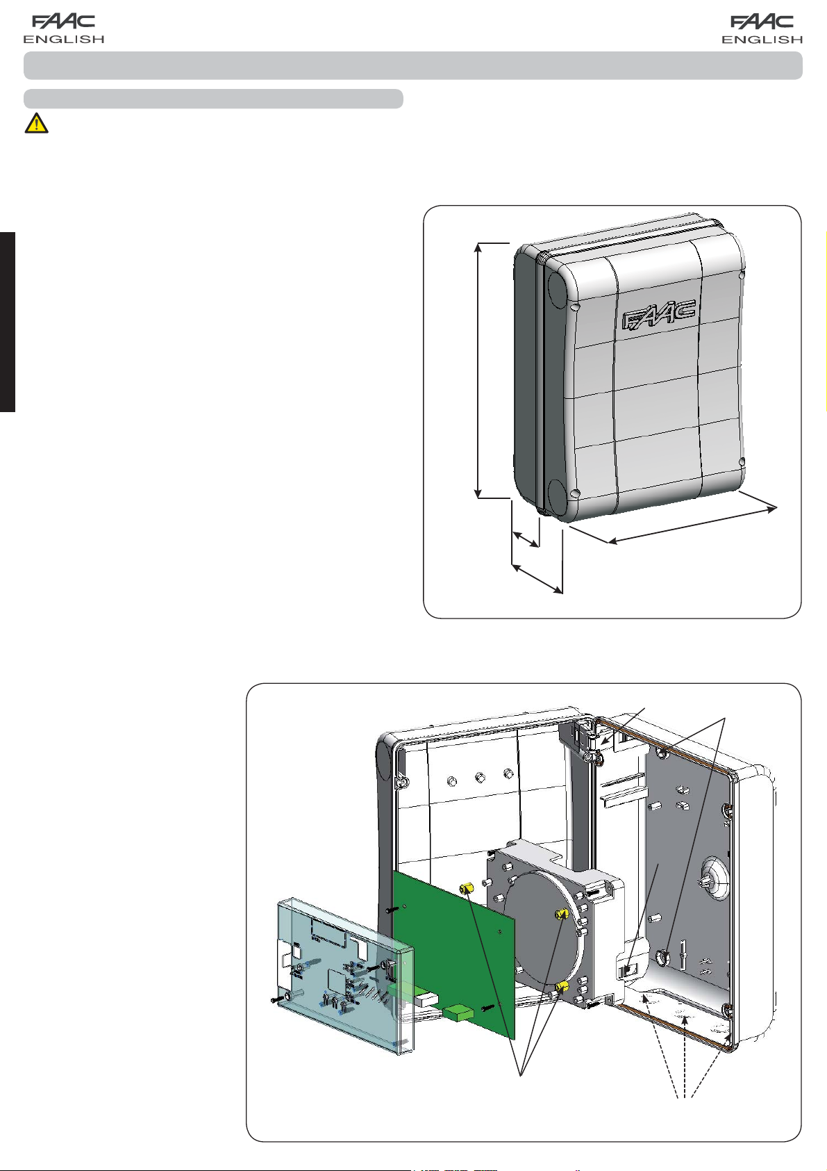
The dimensions of the box are shown in Fig. 1:
ENGLISH
306
Fig. 2 shows the four 5 mm diam.
holes for securing the box (ref.)
to the wall, the three fittings for
installing the cable grippers M16/
M20/M25 (ref. ) and the two lid
hinges (ref. ).
If it is necessary to remove and
re-position the E124 control board,
make sure that the spacers (ref.)
are fitted in the supports.
64
130
225
Dimensions in mm
Fig. 1
2
Fig. 2
Page 5
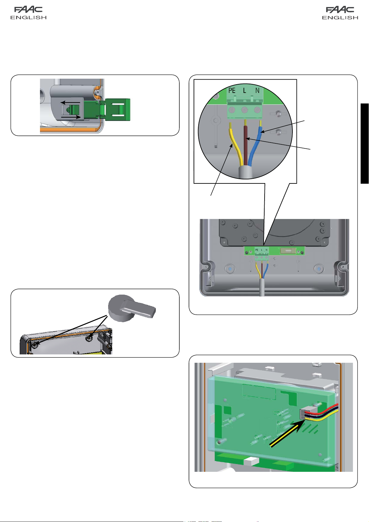
The lid hinges can be moved upward to allow opening the box
housing (Fig. 3): they can also be removed and re-positioned
in order to enable the lid to open to the right or left.
Fig. 3
Connect the power cable to the switching feeder as shown in
Fig.5, making sure that there is an adequate thermal breaker
upstream.
Neutral
Line
ENGLISH
Earth
When you have secured the box in the selected position, cover
the securing holes (Fig. 2 ref. ) and the screws with the supplied
plugs as shown in Fig. 4.
Fig. 4
Fig. 5
Then plug the connector of the transformer to connector J1 on
the board as indicated in fig.6.
Fig. 6
3
Page 6
+
+
2 WARNINGS
Attention: Before attempting any work on the control unit (connections, maintenance), always turn off power.
- Install, upstream of the system, a differential thermal breaker with adequate tripping threshold,
- Connect the earth cable to the relevant terminal (see fig.5).
- Always separate power cables from control and safety cables (push-button, receiver, photocells, etc.). To avoid any
electrical disturbance, use separate sheaths or a screened cable (with the screen earthed).
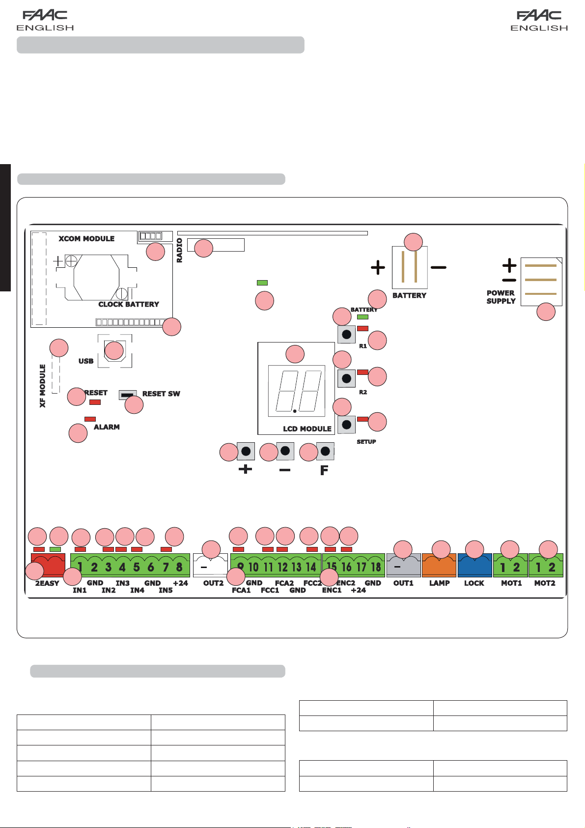
3 LAYOUT AND COMPONENTS OF E124
ENGLISH
J13
DL19
DL20
J15
SW7
M1A
M1A
J14
SW4
DL14
SW5
LCD
SW6
SW1
SW2
SW3
J2
DL15
J1
DL16
DL17
DL18
DL12
DL13
DL1
J3
J4
3.1 INPUTS DEFAULT SETTING
DL2
DL3
DL4
DL5
J5
J6
Terminal-board J4
IN1 OPEN A N.O. contact
IN2 OPEN B N.O. contact
IN3 STOP N.C. contact
IN4 FSW OP N.C. contact
IN5 FSW CL N.C. contact
DL8
DL7DL6
DL9
DL10
J7
DL11
J8 J9 J10 J11
J12
Fig. 7
Connector J13 – XF Module (OMNIDEC)
Channel 1 OPEN A
Channel 2 OPEN B
Connector J14 - Radio
Channel 1 RP OPEN A
Channel 2 RP2 OPEN B
4
Page 7
3.2 DESCRIPTION OF COMPONENTS
LCD SIGNALS AND PROGRAMMING DISPLAY
SW1 “R1” PROGRAMMING PUSH-BUTTON
SW2 “R2” PROGRAMMING PUSH-BUTTON
SW3 “SETUP” PUSH-BUTTON
SW4 “+” PROGRAMMING PUSH-BUTTON
SW5 “-” PROGRAMMING PUSH-BUTTON
SW6 “F” PROGRAMMING PUSH-BUTTON
SW7 “RESET SW” SOFTWARE RESET PUSH-BUTTON
DL1 INPUT STATUS CONTROL LED “IN1”
DL2 INPUT STATUS CONTROL LED “IN2”
DL3 INPUT STATUS CONTROL LED “IN3”
DL4 INPUT STATUS CONTROL LED “IN4”
DL5 INPUT STATUS CONTROL LED “IN5”
DL6 INPUT STATUS CONTROL LED “FCA1”
DL7 INPUT STATUS CONTROL LED “FCC1”
DL8
DL9 INPUT STATUS CONTROL LED “FCC2”
DL10 INPUT STATUS CONTROL LED “ENC1”
DL11 INPUT STATUS CONTROL LED “ENC2”
DL12 SIGNALLING LED FOR DEVICE BUS-2EASY ACTIVE
DL13 SIGNALLING LED FOR BUS 2-EASY DIAGNOSTICS
DL14
DL15 LED SIGNALLING SECONDARY POWER ON (See chap.9)
INPUT STATUS CONTROL LED “FCA2”
LED SIGNALLING PRIMARY POWER ON
DL16
DL17
DL18
DL19 PRESSURE SIGNALLING LED “RESET SW” PUSH-BUTTON
DL20 ALARM SIGNALLING LED “ALARM”
M1A MODULE X-COM CONNECTOR
SIGNALLING LED FOR “SW1” PUSH-BUTTON (R1 PUSH-BUTTON)
SIGNALLING LED FOR “SW2” PUSH-BUTTON (R2 PUSH-BUTTON)
SIGNALLING LED FOR “SW3” PUSH-BUTTON (SETUP PUSH-BUTTON)
J1
POWER FEEDER SWITCHING CONNECTOR (PRIMARY POWER)
J2 SECONDARY POWER SELECTOR
J3 CONNECTOR FOR CONNECTION TO BUS-2EASY DEVICES
J4
CONNECTOR FOR TERMINAL BOARD INPUTS (see chap.4.1)
J5 CONNECTOR FOR OUT2 OUTPUT (see 2nd level prog.)
J6 TRAVEL LIMITS CONNECTOR
J7 CONNECTOR FOR LEAF 1 AND LEAF 2 ENCODER INPUTS
J8 CONNECTOR FOR OUT1 OUTPUT (see 2nd level prog.)
J9 FLASHING LAMP OUTPUT CONNECTOR
J10 CONNECTOR FOR ELECTRICAL LOCK OUTPUT
J11 LEAF 1 MOTOR CONNECTOR
J12 LEAF 2 MOTOR CONNECTOR
J13 CONNECTOR FOR RECEIVER MODULE XF433/XF868
J14 CONNECTOR: DECODER / MINIDEC / RP RECEIVER
J15 USB CONNECTOR FOR PROGRAMMING FROM PC
Flashing LED ALARM indicates alarm in progress
(a situation which does not prejudice gate
operation)
ENGLISH
4 TECHNICAL SPECIFICATIONS
Primary power feed
from mains
Secondary power
feed
Power absorbed
from mains
Max. load
for motor
Power feed
for accessories
Accessories
max. current
Battery charge
current
Operating ambient
temperature
Protective fuses
for unit
Protective fuses for
power pack
with switching power feed
230/115 V~ - 50/60 Hz
(min. 20 Vdc. - max. 28 Vdc.)
BUS-2EASY max. 500 mA
24 Vdc - 16 A max.
stand-by = 4W
~ 400 W
max.
7 A
24 Vdc
24Vdc max. 500 mA
180 mA
(-20 - +55) °C
All self resetting
2.5 A
LED ALARM on steady light indicates error in
progress (a situation which blocks operation
until cause of error is eliminated)
Function logics Semiautomatic, Automatic,
“step-by-step” Semiautomatic, Automatic
with reverse during pause, Automatic
step-by-step, Safety devices automatic,
Safety devices step-by-step automatic,
“b” Semiautomatic, mixed logic “bC”,
Dead-man, Automatic with timer function
Work time
Pause time
Motor power
Motor speed
Connector inputs Switching feeder, Battery,
Terminal board inputs
Terminal board outputs
Programming
Programmable (from 0 to 9 min 50 sec)
Programmable (from 0 to 9 min 50 sec)
Programmable on 50 levels
Programmable on 10 levels
Decoder/Minidec/RP, X-COM, module
XF433/868, USB
BUS-2EASY, Inputs from IN1 to IN5 (see
par. 5), Travel limit device, Encoder.
Flashing lamp, Motors, Electrical lock,
OUT1, OUT2 (programmable), power feed
to accessories
1st and 2° lev. with 3 keys (+, -, F) and LCD
display.
3rd lev. with P.C. connected via USB or with
X-COM module.
5
Page 8
5 TERMINAL BOARDS, CONNECTORS, INPUTS AND SIGNALS
5.1
TERMINAL BOARD J3 – CONNECTION TO BUS-2EASY ACCESSORIES
Terminal for connection of BUS-2EASY accessories. see
par. 6.2
5.2 TERMINAL BOARD J4 – SIGNALS INPUTS
IN4 - Opening safety-devices contact (N.C. - terminal 5):
see paragraph 6.1.
To install several opening safety devices, connect
the N.C. contacts in series.
Other more detailed programming possibilities
are feasible by programming with a PC (see
dedicated instructions).
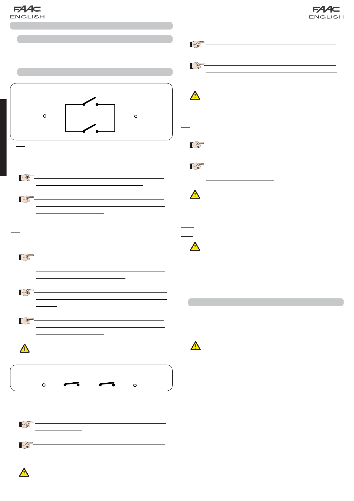
Connection of 2 N.O. contacts in parallel
Fig. 8
IN1 - OPEN A - “Opening” Command (N.O. - terminal 1):
this refers to any pulse generator (e.g.: push-button) which,
ENGLISH
by closing a contact, commands TOTAL OPENING.
To install several total opening pulse generators,
connect the N.O. contacts in parallel
Other more detailed programming possibilities
are feasible by programming with a PC (see
dedicated instructions).
IN2 - OPEN B - Partial Opening” command (N.O. - terminal 3):
this refers to any pulse generator (e.g.: push-button) which,
by closing a contact, commands PARTIAL OPENING.
For double leaf or single leaf systems, OPEN
B commands an opening of leaf 1 (motor 1)
corresponding to 50% of total opening (can
be modified by PC up to 100%)
If opening safety devices are not connected,
jumper connect terminals IN4 and GND, if the
FAIL-SAFE safety device is not active, otherwise
jumper connect IN4 and –OUT1.
IN5 - Closing safety-devices contact (N.C. -. terminal 7): see
paragraph 6.1.
To install several closing safety devices, connect
the N.C. contacts in series
Other more detailed programming possibilities
are feasible by programming with a PC (see
dedicated instructions).
If closing safety devices are not connected,
jumper connect terminals IN5 and GND, if the
FAIL-SAFE safety device is not active, otherwise
jumper connect IN5 and –OUT1.
GND - (terminals 2-6): Negative for powering accessories
+24 - (terminal 8): Positive to power feed accessories
The max. load of the accessories is 500mA,
subdivided among terminal boards J4 and J7.
To calculate maximum absorption, refer to the
instructions for individual accessories.
To install several partial opening pulse
generators, connect the N.O. contacts in
parallel
Other more detailed programming possibilities
are feasible by programming with a PC (see
dedicated instructions).
If you select one of the following logics (b, bC,
C) input IN2 automatically becomes CLOSE
(N.O).
Connection of 2 NC contacts in series
Fig. 9
IN3 - STOP contact command (N.C. - terminal 4): this refers to
any device (e.g.: push-button ) which, by opening a contact,
can stop the motion of the automated system.
To install several STOP devices, connect the N.C.
contacts in series.
Other more detailed programming possibilities
are feasible by programming with a PC (see
dedicated instructions).
5.3 TERMINAL BOARDS J5, J8 – OUT1 AND OUT2
The two outputs can be set in one of the functions described
in 2nd level programming (see par.7.2.). The default value is:
OUT1 = ALWAYS ACTIVE
OUT2 = INDICATOR LIGHT.
Maximum load applicable on every output:
24 Vdc with 100 mA.
If stop safety devices are not connected, jumper
connect the STOP and GND terminals.
6
Page 9
5.4
TERMINAL BOARD J6 – OPENING AND CLOSING TRAVEL LIMIT DEVICE
Terminal board for connection of the opening (FCA1 and FCA2)
and closing (FCC1 and FCC2) travel limit device.
The travel limit contacts FCC1, FCA1, FCC2
and FCA2 are all NC contacts. See 2nd level
programming for the various configurations
applicable to the travel limit inputs.
5.8 TERMINAL BOARD J11, J12 - MOTORS
J11 (MOT1): Connection of motor connected to leaf 1, i.e. the
leaf which opens first during an opening operation.
J12 (MOT2): Connection of the motor connected to leaf 2,
i.e. the leaf which opens second.
If only one motor is connected, it must be
connected to terminal J11 (MOT1).
If they are not used, do not jumper connect the contacts
of the limit switches FCC1, FCA1, FCC2, FCA2
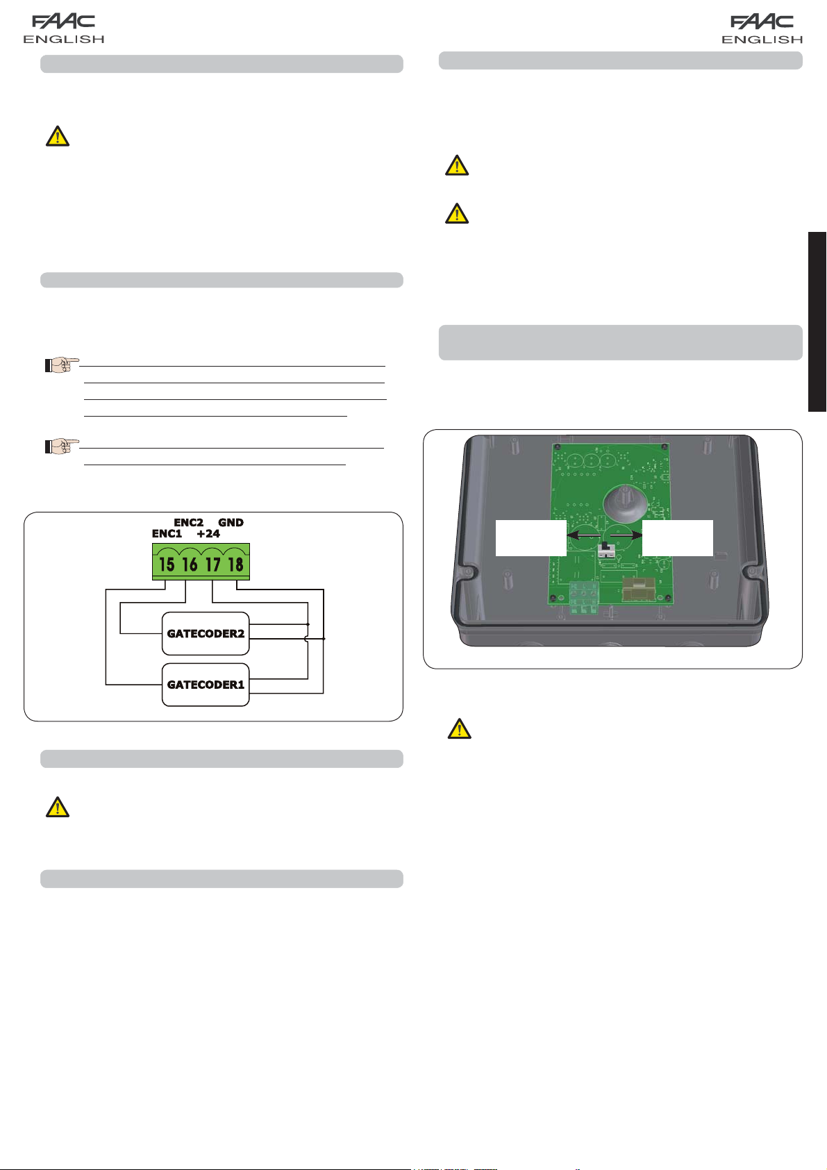
5.5 TERMINAL BOARDS J7 - ENCODERS
Encoders with an open collector signal referred to earth (e.g.
Gatecoder) can be connected to detect the leaf’s angular
position. For connections, see fig. 10.
The configuration indicated in the drawing is
the maximum one. Only 1 Gatecoder can be
used. In this case, the unused inputs do not
have to be jumper connected to earth
The default obstacle detection and stop point
times are 2 and 4 seconds respectively.
If, during the first movement of the SETUP
procedure, the leaves open instead of closing,
the motor connection cables must be changed
over.
5.9 CONNECTOR J1 - PRIMARY POWER FEED FROM
230/115 V MAINS
J1: Select the correct power feed, by turning the power switching
selector to its correct position (Default 230 Vac.)
115 Vac
230 Vac
ENGLISH
WHITE
WHITE
5.6 TERMINAL BOARD J9 – FLASHING LAMP
RED
BLACK
RED
BLACK
Output for 24Vdc flashing lamp
Maximum applicable load: 24 Vdc - 15 W
5.7 TERMINAL BOARD J10 – ELECTRIC LOCK
Output for 12V ac or 24V dc electric lock
Fig. 10
To ensure correct operation, the switching
feeder must be connected to the earth
conductor in the system. Install an adequate
differential thermal breaker upstream of the
system.
Fig. 11
7
Page 10
E124
J6
5.10 CONNECTOR J2 - SECONDARY POWER FEED
J2: In the absence of a primary feed from the mains, the
control unit can be fed by a secondary low voltage (24Vdc)
power feed. Power can be supplied by a pack of batteries,
recharged by a battery charger integrated in the board,
or by a stabilised power feeder. In both cases, the power
supply must have the following characteristics:
Voltage: (24 ± 4) Vdc
Current: 16 A max.
If you use an external stabilised feeder, you
must disable the “battery charger” function
via the PC (see dedicated instructions).
ENGLISH
5.11 CONNECTOR J13 – XF MODULE RAPID CONNECTION
The control unit has an integrated 2-channel decoding system
(DS, SLH, LC/RC) named OMNIDEC. This system makes it possible
to save – through an extra receiver module – F433 or XF868
(Fig.12 ref.) – radio commands of the same frequency, but
of a different type (DS, SLH, LC/RC). It is possible to save both
total opening (OPEN A) and partial opening (OPEN B) of the
automated system, up to a maximum of 256 channels.
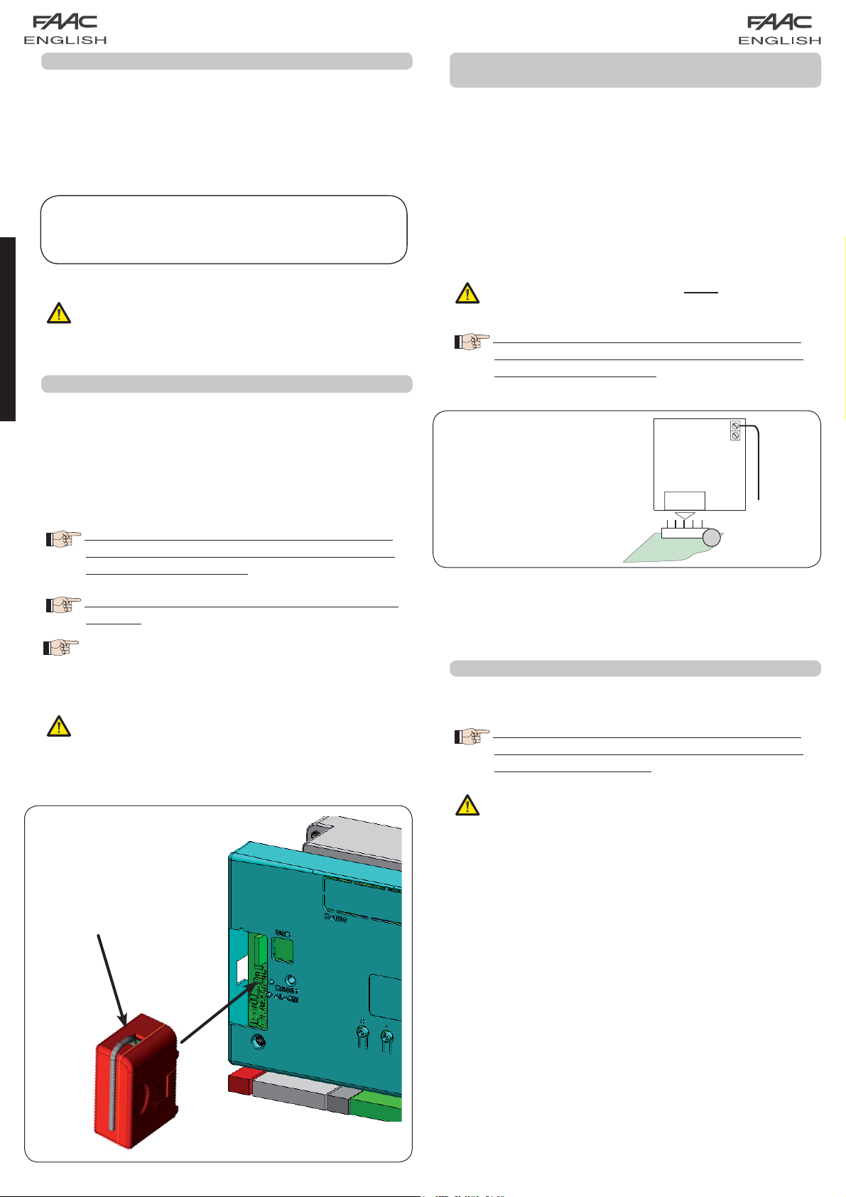
5.12 CONNECTOR J14- FOR RAPID CONNECTION OF MINIDEC,
DECODER AND RP
It is used for rapid connection of Minidecs, Decoders and RP/RP2
Receivers.
If you are using an RP2 twin-channel receiver, you will be able
to directly command two different radio channels, OPEN A
and OPEN B of the automated system from a twin-channel
radio control.
If using a single-channel Minidec, Decoder or RP, you can
command only one radio channel, OPEN A.
Fit the accessory with the components side directed toward
the board interior.
Insert and remove the boards ONLY after cutting
power.
Other more detailed programming possibilities
are feasible by programming with a PC (see
dedicated instructions).
An example of a radio
accessory connection
Other more detailed programming possibilities
are feasible by programming with a PC (see
dedicated instructions).
To save the radio commands, refer to
Chap.8.
The function of the 2nd channel (by default OPEN B)
can be changed if associated with the activation of
a programmable output.
(see 2ND LEVEL progr.
o1 and o2 parameter 14-15)
Insert and remove the boards only after cutting
power.
J14
5.13
CONNECTOR M1A – RAPID CONNECTION MODULE X-COM
Fig. 13
An X-COM module can be connected to this connector, used
for radio communication between board and PC.
Other more detailed programming possibilities
are feasible by programming with a PC (see
dedicated instructions.
Insert and remove the module only after
cutting power.
Fig. 12
8
Page 11

RX CL TX CL
+
+
J4
OUT1
6 ELECTRICAL CONNECTIONS
*
* *
To connect
the photocells
and safety
devices, consult
paragraph 6.1
Max load 24Vdc - 500mA
Enable in
nd
2
level
programming
LAMP
LOCK
ENGLISH
Use with motors
without a BUS-2EASY
encoder
(see par.5.5)
Fig. 14
With the E124 control unit, you can use both traditional
photocells (N.C. contact with relay) and/or photocells with
BUS-2EASY (open collector contact). The positioning of the
photocells and their operation is schematised in Fig. 15.
6.1 TRADITIONAL PHOTOCELLS
Before you connect the photocells we advise you to select
the type of operation according to the movement zone they
have to protect:
Closing safety devices:
automated system closing movement, and, therefore,
are suitable for protecting the closure zone against the
risk of impact
Opening safety devices: they are tripped only during the
automated system opening movement, and, therefore,
are suitable for protecting the opening zone against the
risk of impact
Opening /closing safety devices: they are tripped during the
automated system opening and closing movement, and,
therefore, are suitable for protecting the entire movement
zone against the risk of impact
.
.
they are tripped only during the
.
Connection of 1 pair of closure photocells
with FAIL-SAFE
Set o1 = 01 in the second programming level
Other safety devices
Connection of 1 pair of closure photocells
with FAIL-SAFE and STOP
activated
de-activated
OUT1
OUT1
Opening /closing safety devices
Closing safety devices
Fig. 15
Opening
safety devices
Other safety devices
Fig. 16
9
Page 12

RX CL1 TX CL1
RX CL2TX CL2
+
+
+
+
J4
Connection of 2 pairs of photocells
Connection of a pair of closing photocells, a pair of
opening photocells and a pair of opening/closing photocells
J4
Other safety
Fig. 17
ENGLISH
Other safety
devices
devices
Connection of 1 pair of opening photocells
J4
RX OP TX OP
+
TX CL
+
Fig. 18
+
RX OP/CLTX OP/CL
+
RX OP TX OP
+
Connection of a pair of opening
and a pair of closing photocells
J4
RX OP
TX OP
+
+
+
Fig. 21
Connection of one closing safety device and
one opening safety device
J4
Fig. 19
Connection of no safety device and stop
Fig. 20
If you do not use the FAILS-SAFE device, you
must connect the transmitters power feed to
terminals 6 and 8 of J4.
If you use the FAIL-SAFE device, connect the
transmitters power feed to OUT1 after you have
set it appropriately (see 2nd level programming
and fig. 16).
If you use the FAIL-SAFE device, the non-used
safety inputs too must be jumper connected
to the OUT1 negative (see Fig.16).
10
+
TX CL
+
Connection of a pair of closing
and a pair of opening/closing photocells
TX CL
+
RX OP/CLTX OP/CL
+
J4
+
+
Fig. 22
+
+
Fig. 23
Page 13

6.2 PHOTOCELLS BUS-2EASY
This board is supplied with a BUS-2EASY circuit enabling easy
connection of a high number of BUS-2EASY safety auxiliary
devices (e.g. up to 16 photocells pairs), appropriately
programmed, using only two cables without polarity.
Before connecting the photocells, we advise you to select the
type of operation (Fig.24) according to the movement zone
they must protect and position – both on the transmitter and
receiver - the dip-switches as shown in Tab.1:
Closing photocells:
they are tripped only during the
automated system closing movement, and, therefore,
are suitable for protecting the closure zone against the
risk of impact
.
If you have to connect two or more BUS-2EASY
closing photocells, choose different addresses
for each pair used.
Opening photocells:
they are tripped only during the
automated system opening movement, and,
therefore, are suitable for protecting the opening zone
against the risk of impact
.
If you have to connect two or more
BUS-2EASY opening photocells, choose
different addresses for each pair used.
Opening /Closing photocells:
they are tripped during the
automated system opening and closing movement,
and, therefore, are suitable for protecting the entire
movement zone against the risk of impact
.
If you have to connect two or more BUS-2EASY
closing photocells, choose different codes for
each pair used.
Fig. 24 shows a 2-swing leaf automated system indicating the
coverage beams of the photocells:
A: Photocells with OPENING and CLOSING action
B: Photocells with OPENING action
C: Photocells with OPENING action
D: Photocells with CLOSING action
6.2.1 ADDRESSING THE BUS-2EASY PHOTOCELLS
Important: the same address must be given
to both transmitter and receiver. (the same
DIP-SWITCH setting)
Make sure that there are not two or more
photocell pairs with the same address. (the
same DIP-SWITCH setting)
If you are not using any BUS-2EASY accessory,
leave free connector BUS-2EASY (J3- fig. 7).
DL1 = Alignment
RX TX
DL2 = BUS-2EASY/
power supply status
DS1 = Programming
1 2 3 4
DL2
ON
dip-switches
DS1
BUSBUS
Fig. 25
RX - TX
DL2
DL1
ON
1 2 3 4
DS1
BUSBUS
Table 1 shows the programming operations of the dip-switch
inside the transmitter and the BUS 2-EASY photocells receiver.
ENGLISH
Pulse generators: used as pulse generators to open the
automated system
.
A maximum of 16 pairs of BUS-2EASY photocells can be
connected to the board.
The photocells are split into groups:
Opening photocells: max 6
Closing photocells: max 7
Opening /Closing photocells: max 2
Photocell used as an OPEN pulse: max 1
Tab. 1 - Addressing the BUS-2EASY photocells
Dip1 Dip2 Dip3 Dip4 Ref. Type
OFF OFF OFF OFF
OFF OFF OFF ON
OFF OFF ON OFF
OFF OFF ON ON
OFF ON ON OFF
OFF ON ON ON
ON OFF OFF OFF
ON OFF OFF ON
ON OFF ON OFF
ON OFF ON ON
ON ON OFF OFF
ON ON OFF ON
ON ON ON OFF
OFF ON OFF OFF
OFF ON OFF ON
ON ON ON ON / OPEN PULSE
B - C OPENING
D CLOSING
A
OPENING
and CLOSING
Fig. 24
Other more detailed programming possibilities are feasible
by programming with a PC (see dedicated instructions).
11
Page 14

6.2.2 MEMORY STORAGE OF BUS-2EASY ACCESSORIES
You can add the BUS-2EASY accessories to the system at any
time, simply by memory-storing them on the board, observing
the following procedure:
Install and program the accessories using the required
1.
address (see parag. 6.2.1).
Cut power to the board.
2.
Connect the two cables of the BUS-2EASY accessories to
3.
the red terminal-board J3 (any polarity will do).
Power the board, taking care to first connect plug J1 of the
4.
main power supply (coming from the switching feeder) and
then, connector J2 of any batteries.
Quickly press once only the SETUP (SW3) push-button,
5.
to execute learning. Check operation of the installed
BUS-2EASY devices.
The board has memory stored the BUS-2EASY accessories.
ENGLISH
Follow the instructions in the table below to check if the
BUS-2EASY connection is correct.
Tab. 2 - Description of LED DL12 (RED)
6.2.3 ADDRESSING THE BUS-2EASY ENCODERS
Connection of the BUS-2EASY input in the control board is via
the bipolar cables which come out of the encoders.
Unlike the case of the photocell devices, the
polarity of the BUS-2EASY line connection
determines whether the encoder belongs to
one leaf rather than to the other.
This is why you must pay great attention to the indications of
the status LEDs on the body of each encoder (Fig. 26).
Below we list the functions of LEDs DL1, DL2, and DL3, and their
statuses:
Tab. 4 - Encoder connection and LED status
LED ON FLASHING OFF
Power ON and
BUS -2EASY
DL 1
communicating
Power ON but
BUS-2EASY not
communicating
No power to or
communication
with BUS-2EASY
with board
Leaf 1 encoder / Leaf 2 encoder
DL 2
Leaf not moving Pulses read while
DL 3
leaf moving
Leaf not moving
ON
OFF
Safety device engaged or pulse generator
active
NO safety device engaged and NO pulse
generator active
Tab. 3 - Description of LED DL13 (GREEN)
Steady light
OFF
Normal activity (LED Lighted even if no
photocells)
Line BUS-2EASY short circuiting (flash every
2.5 sec.)
Error detected in BUS-2EASY connection
error, repeat the acquisition procedure. If
Fast flashing
the error is repeated, make sure that there
is not more than one accessory with the
same address in the system (also see the
accessories instructions).
ENCODER WIRING FOR OPERATOR S700H
DL1 ON
TWO LEDs ON
LEAF 1*
DL 1 must always be lighted to guarantee correct
•
connection between encoder and board.
DL 2 determines the leaf on which the encoder is installed.
•
Providing the configuration is correct, the automated
system will show: an encoder with DL2 lighted in leaf
1, and an encoder with DL2 OFF in leaf 2. If there is an
incorrect connection, i.e. indicating two encoders with
the same status of the DL2 LEDs, during the learning
procedure of the BUS-2EASY accessories, the DL 1 LEDS
of both encoders show a FLASHING status. In this situation,
refer to the configuration in TAB.4 to define which encoder
connection to rotate.
DL 3 indicates, on a steady flashing beam, the reading
•
of the pulses while the leaf is moving. When the leaf is
motionless, DL 3 can be either lighted or OFF.
DL3 OFF
LEAF
2
DL2 OFF
ONE LED ON
Leaf 1 Leaf 2
DL2 ON
DL3 OFF
DL1 ON
LEAF 2
ONE LED ON
Leaf 2
DL3 OFF
*
LEAF 1 OPENS AS FIRST AND CLOSES AS SECOND.
IF NO REBATE IS PRESENT BETWEEN LEAF 1 AND
2, SET LEAF DELAY TO ZERO ON THE CONTROL
BOARD.
DL2 OFF
DL1 ON
DL2 ON
DL3 OFF
LEAF 1*
TWO LEDs ON
12
Leaf 1
DL1 ON
REVERSE THE ENCODER WIRES TO EXCHANGE
BETWEEN THE ENCODER ASSOCIATED WITH LEAF
1 AND THE ENCODER ASSOCIATED WITH LEAF 2
AND VICE VERSA
Fig. 26
Page 15

ENCODER WIRING FOR OPERATOR S450H
DL 1
DL 2
DL 3
DL 1
DL 2
DL 3
LEAF 1*
THROUGH THE BRACKET COVERING
HOUSING, MAKE SURE THAT LEDs DL1
AND DL2 ARE LIGHTED ON LEAF 1,
WHEN THE MOTOR IS AT REST
LEAF 1
TWO LEDs ON
LEAF 2
THROUGH THE BRACKET COVERING
HOUSING MAKE SURE THAT LED DL1 IS
LIGHTED ON LEAF 2, WHEN THE MOTOR
IS AT REST
LEAF 2
ONE LED ON
LEAF 2
THROUGH THE BRACKET COVERING
HOUSING MAKE SURE THAT LED DL1 IS
LIGHTED ON LEAF 2, WHEN THE MOTOR
IS AT REST
LEAF 2
ONE LED ON
LEAF 1*
THROUGH THE BRACKET COVERING
HOUSING, MAKE SURE THAT LEDs DL1
AND DL2 ARE LIGHTED ON LEAF 1,
WHEN THE MOTOR IS AT REST
LEAF 1
TWO LEDs ON
DL 1
DL 2
DL 3
DL 1
DL 2
DL 3
ENCODER WIRES REVERSING OPERATION
ENCODER
LEAF 1
*
LEAF 1 OPENS AS FIRST AND CLOSES AS SECOND.
IF THERE IS NO REBATE BETWEEN LEAF 1 AND 2,
SET THE LEAF DELAY TO ZERO ON THE CONTROL
BOARD.
REVERSE THE ENCODER WIRES TO EXCHANGE
BETWEEN THE ENCODER ASSOCIATED WITH LEAF
1 AND THE ENCODER ASSOCIATED WITH LEAF 2,
AND VICE VERSA
ENCODER
LEAF 2
ENGLISH
7. PROGRAMMING
To program the operation of the automated system, you must
access the “PROGRAMMING” mode.
Programming is in two parts: 1st LEVEL, 2nd LEVEL.
On activation of the board, the display shows
bo and, for 3 seconds, the fw version of the
board.
The status of the automated system is shown
on the display. If “PC” appears on the display
when the F push-button is pressed, this means
that programming with the PC is loaded on the
board. If no password was set, you can only
modify parameters
Lo-PA-Pb. To modify the
other programming parameters, reload the
default of the motor used (in this case the PC
programming will be replaced by the default
parameters of the board)
If dF appears on the display when you press
key F (and hold it down), this means that you
have entered 1st level programming (see
parag. 7.1).
Modification of the programming
parameters is immediately effective, whereas
definitive memory-storage occurs only on
exiting programming and returning to the
view of the inputs status. If you cut power to
the equipment before returning to view the
inputs status, all the modifications made will
be lost.
You can return to the inputs status display,
and save all the parameters modified up
till then, from any point of 1st and 2nd level
programming by simultaneously pressing keys
F and -.
To restore the default settings, recharge the
required default during the first passage of 1st
level programming.
7.1. 1ST LEVEL PROGRAMMING
If PC appears when you press any button on the display, this means that programming from the PC with a protection password
is loaded on the board. Nothing can be modified without the PC and relevant protection password. Connect the PC to the USB
to view and/or modify programming, using the dedicated instruction.
st
Press push-button F to access 1
If you press key F (and hold it down) the name of the function appears on the display.
•
If you release the push-button, the display shows the value of the function, which can be changed with keys + and -.
•
If you press F again (and hold it down), the display shows the name of the next function, etc.
•
When you have reached the last function, press key F to exit programming and save the parameters. The display resumes
•
level programming.
showing the automated system status.
13
Page 16

ST
1
LEVEL PROGRAMMING
Display Function
dF
DEFAULT:
0 Configures the parameters with DEFAULT values
1 Configures the parameters with DEFAULT values
2 Configures the parameters with DEFAULT values
3 Configures the parameters with DEFAULT values
ENGLISH
4 Configures the parameters with DEFAULT values
5 Configures the parameters with DEFAULT values
CU If the CU value appears when you release
corresponding to an installation with non-FAAC
operators. (see default column 0).
corresponding to an installation with operators
FAAC 412, 413/415, 770, 390 (see default
column 1).
corresponding to an installation with operators
FAAC 391 (see default column 2).
corresponding to an installation with operators
FAAC S700H (see default column 3
corresponding to an installation with operators
FAAC 418. (see column default 4).
corresponding to an installation with operators
FAAC S450H (see column default 5).
the F push-button, this means that a standard
configuration modified by push-buttons and
display was selected. If you wish to maintain this
programming, press push-button F again.
.
Default 0Default
0
1 2345
1
Default 2Default
3
Default 4Default
5
MO
LO
PC If the PC value appears when you release the F
push-button, this means that programming from
the PC was effected with the default password
(0000). By pressing the + and - keys, you can
load a default configuration from among
those listed above. If you wish to maintain
programming from the PC, press push-button F
again.
TYPE OF MOTOR:
00 non-FAAC operators.
1 operators FAAC 412, 413/415, 770, 390.
2 operators FAAC 391.
3 operators FAAC S700H.
04 operators FAAC 418
05 operators FAAC S450H
View only parameter, cannot be modified
FUNCTION LOGICS:
E Semi-automatic.
EP Semi-automatic “Step by step”.
S “Safety devices” automatic.
SA Automatic with in-pause reversing.
SP ”Step-by-step safety devices” automatic.
A1 Automatic 1.
A Automatic.
AP Automatic “Step-by-step”.
At Automatic with timer function.
b Semi-automatic “b”.
bC Mixed (OP at impulse/CL Dead-man).
C Dead-man.
CU Custom.
00 01 02 03 04 05
EEEEEE
Other more detailed programming
possibilities are feasible by programming
with a PC (see dedicated instructions).
14
Page 17

Display Function
PA
PAUSE TIME A:
Pause time following a TOTAL opening command. It has
only effect if a logic with pause time was selected. Can
be adjusted from 0 to 59 sec. in one-second steps.
Next, the viewing changes in minutes and ten seconds
(separated by a dot) and time is adjusted in 10-second
steps, up to the maximum value of
E.g.: if the display shows
min. and 50 sec.
PAUSE TIME B:
Pb
Pause time following a PARTIAL opening command. It has
only effect if a logic with pause time was selected. Can
be adjusted from 0 to 59 sec. in one-second steps.
Next, the viewing changes in minutes and ten seconds
(separated by a dot) and time is adjusted in 10-second
steps, up to the maximum value of
E.g.: if the display shows 2.5, the pause time will be 2
min. and 50 sec.
F1
MOTOR 1 POWER:
Adjusts the maximum power level of motor 1.
9.5 minutes.
2.5, the pause time will be 2
Other more detailed programming
possibilities are feasible by programming
with a PC (see dedicated instructions).
9.5 minutes.
Other more detailed programming possibilities
are feasible by PC programming (see
dedicated instructions).
Default
0
Default
1
Default 2Default 3Default 4Default
20 20 20 20 20 20
20 20 20 20 20 20
25 25 25 40 25 35
5
ENGLISH
F2
SP
MOTOR 2 POWER:
Adjusts the maximum power level of motor 2.
01 = minimum power
SPEED:
Adjusts the motion speed of the motors. There are 10
levels. The value is relative and not absolute, because
the speed value refers to the weight of the leaf measured
during the SETUP cycle
01 = minimum power
50 = maximum power
Other more detailed programming
possibilities are feasible by programming
with a PC (see dedicated instructions).
If the power value is changed, we
advise you to execute a new SETUP (see
parag.10.1)
50 = maximum power
Other more detailed programming
possibilities are feasible by programming
with a PC (see dedicated instructions).
If the power value is changed, we
advise you to execute a new SETUP (see
parag.10.1)
25 25 25 40 25 35
08 08 08 08 08 08
01 = minimum speed
10 = maximum speed
Other more detailed programming
possibilities are feasible by programming
with a PC (see dedicated instructions).
15
Page 18

Display Function
rL
St
DECELERATION:
Adjusts deceleration space as a percentage of the
total travel of the leaves. Adjustable from
in 1% steps.
00 = no deceleration
AUTOMATED SYSTEM STATUS:
Exit from programming, storage of data and return to the automated system status view
00 to 99 %.
01 = minimum deceleration space
99 = maximum deceleration space
Other more detailed programming
possibilities are feasible by PC programming
(see dedicated instructions).
Default
0
Default
1
Default 2Default 3Default 4Default
30 30 30 20 20 20
5
ENGLISH
00 = CLOSED
01 = OPEN
02 = Idle then “OPENS”
03 = Idle then “CLOSES”
04 = In “PAUSE”
05 = At opening stage
07 = FAIL SAFE in progress
08 = verification of BUS-2EASY devices in progress
09 = Pre-flashing then “OPENS”
10 = Pre-flashing then “CLOSES”
11 = Opening in EMERGENCY status
12 = Closing in EMERGENCY status
06 = At closing stage
7.2. 2nd LEVEL PROGRAMMING
To access 2ND LEVEL PROGRAMMING, press push-button F and, while holding it down, press push-button +:
if you release the + key, the display shows the name of the first second level function (if the
•
that programming was effected from the PC).
if you also release the F push-button, the display shows the value of the function, which can be changed with keys + and -.
•
•
if you press the F key (and hold it down), the display shows the name of the next function; if you release it, the values is
shown and can be modified with keys + and -.
•
when you reach the last function, press the F push-button to exit programming, and the display resumes showing the
automated system status.
If programming via the PC with personalised password was effected, you CANNOT enter 2nd level
programming.
2nd LEVEL PROGRAMMING
Display Function
bo
EL
MAXIMUM POWER AT THRUST:
The motors run at maximum power for the time set
(ignoring the selected power level F1 and F2) during
motion thrust.
Adjustable from
ELECTRIC LOCK ON LEAF 2:
The board has a terminal dedicated to the connection
of an electric lock. Normally the electric lock must be
connected to leaf 1. If the electric lock is located on
leaf 2, adjust the parameter.
00 to 06 seconds in 1-second steps.
Other more detailed programming
possibilities are feasible by PC programming
(see dedicated instructions).
Default
0
Default
1
Default
02 02 02 02 02 02
no no no no no no
dF value persists, this means
2
Default
3
Default
4
Default
5
cd
Y = electric lock on leaf 2
no = electric lock on leaf 1
LEAF DELAY AT CLOSING:
Adjusts leaf delay at closing.
Adjustable from 00 to 60 seconds in 1-second steps.
00 = no delay
01 = minimum delay
60 = maximum delay
16
05 05 05 05 05 05
Page 19

Display Function
od
LLEAF DELAY AT OPENING:
Opening of leaf 2 is delayed with respect to leaf 1,
avoiding thus interferences between the leaves.
Y = active
no = excluded
t
r8
WORK TIME (time-out):
We advise you to set a value longer than the time required by the gate to open and close completely.
Can be adjusted from
Next, the viewing changes in minutes and ten seconds
(separated by a dot) and time is adjusted in 10 second
steps, up to the maximum value of
SPACE OF TRAVEL STOP SEARCH:
The set level, from
search for the travel stop referred to total travel of the
leaves. For the default values
50 corresponds to 40% of total travel, whereas for the
default values
of total travel.
Leaves do not reverse in the space of the search for the
travel stop in the event of an obstacle.
cS
FINAL CLOSING THRUST:
The motors are run at maximum power to facilitate coupling with the electric lock (over pushing stroke).
Y = active
no = excluded
01 to 59 sec. in 1 second steps.
9.5 minutes.
01 to 50, adjusts the space of the
0-1-2-4, the value
3-5, the value 50 corresponds to 20%
Default
0
Default
1
Default 2Default 3Default 4Default
YYYYYY
4.1 4.1 4.1 4.1 4.1 4.1
20 20 20 08 20 08
no no no no no no
5
ENGLISH
rS
SF
PF
Other more detailed programming pos-
sibilities are feasible by programming with
a PC (see dedicated instructions).
REVERSING STROKE AT OPENING:
When the gate is closed before opening, the motors
push to close to facilitate uncoupling the electric clock
(reversing stroke).
SOFT TOUCH:
After touching the travel stop point, the leaves reverse
and then rest gently.
PRE-FLASHING:
Enables you to select 5 types of pre-flashings of 3 sec.
duration.
Y = active
no = excluded
Other more detailed programming pos-
sibilities are feasible by programming with
a PC (see dedicated instructions).
Y = active
no = excluded
This function can be useful to respect
the impact curve specified by current
standards.
Other more detailed programming
possibilities are feasible by PC programming
(see dedicated instructions).
no = no pre-flashing.
OC = pre-flashing before every movement.
CL = pre-flashing before a closing motion.
OP = pre-flashing before an opening motion.
PA = pre-flashing at end of pause only
no no no no no no
no no no no no no
no no no no no no
Other more detailed programming pos-
sibilities are feasible by programming with
a PC (see dedicated instructions).
17
Page 20

Display Function
Display Function
FA
TRAVEL-LIMIT STOP AT OPENING:
The use of travel limit stops at opening enables us to
indicate the point after which the equipment search for the
mechanical stop point (
the automated system (
00 = no travel limit device at opening for both leaves
01= searches for stop point of leaf 1 and 2
02 = searches for stop point of leaf 1
03 = searches for stop point of leaf 2
04 =
05 = stops movement of leaf 1
06 = stops movement of leaf 2
ENGLISH
FC
TRAVEL-LIMIT STOP AT CLOSING:
The use of travel limit stops at closing enables us to indicate the
point after which the equipment search for the mechanical stop
point (
system (
00 = no travel limit device at closing for both leaves
01= searches for stop point of leaf 1 and 2
02 = searches for stop point of leaf 1
03 = searches for stop point of leaf 2
04 =
05 = stops movement of leaf 1
06 = stops movement of leaf 2
01
, 02, 03) or to immediately stop
04, 05, 06
stops movement of leaf 1 and 2
By changing limit switches setting,
the letters
(DL18) LED flash on the display, to
indicate that the SETUP must be
executed when exiting the programming
menu. If the limit switch is used, the
SOFT-TOUCH function, if enabled, is not
carried out
01, 02, 03
04, 05, 06
stops movement of leaf 1 and 2
S0 together with the SETUP
.
) or to immediately stop the automated
):
):
0
Default
0
Default
Default
1
Default 1Default 2Default
Default 2Default 3Default 4Default
00 00 00 00 00 00
00 00 00 00 00 00
3
5
SE
US
By changing limit switches setting,
the letters
(DL18) LED flash on the display, to
indicate that the SETUP must be
executed when exiting the programming
menu. If the limit switch is used, the
SOFT-TOUCH function, if enabled, is not
carried out
OBSTACLE SENSITIVITY:
Change this parameter to set the time after which, in
the event of an obstacle, the board commands leaf
reversal, or leaf stop if the leaves are within the space
for the travel limit search (see parameter
The fourth consecutive obstacle detected in the same
direction is considered as the travel stop and the leaf
stops in that position.
S0 together with the SETUP
.
rB).
01 = minimum sensitivity
10 = maximum sensitivity
ULTRA-SENSITIVITY:
This function activates an obstacle detection system,
based on the control of the variation of the current
absorbed by the motor, causing immediate leaf
reversal.
10 08 08 07 08 07
no no no no no no
Y = active
no = excluded
18
Page 21

Display Function
Ph
Ad
ANTI WIND: (function only active with FAAC operators without
encoder)
Adjusts intervention time of the anti-wind function, which
enables the gate to operate even if there are gusts of
wind. After the set time, the board commands reverse
motion.
Can be adjusted from
Next, the viewing changes in minutes and ten seconds
(separated by a dot) and time is adjusted in 10 second
steps, up to the maximum value of
E.g.: if the display shows
be 1 min and 50 sec. If the selected time is
function is disabled.
00 = function disabled
2.0 = function active for maximum time
ADMAP FUNCTION:
This is used to activate operation according to French
regulations NFP 25/362.
Y = active
no = excluded
o1
OUT 1:
Used for setting the OUT1 output (open collector N.O.):
0 to 1 min. in one second steps.
2. 0 minutes.
1.5, the intervention time will
00 the
Default
0
Default
1
Default 2Default 3Default 4Default
no no no no no no
no no no no no no
00 00 00 00 00 00
5
ENGLISH
00 = Always active
01 = FAIL-SAFE
02 = INDICATOR LIGHT (off when closed, lighted during
opening and open/pause, flashes during closing)
03 = COURTESY LIGHT (see next parameter)
04 = ALARM on BATTERY operation
05 = gate OPEN or in PAUSE
06 = gate CLOSED
07 = gate MOVING
08 = gate in EMERGENCY status
09 = gate OPENING
10 = gate CLOSING
11 = ELECTRIC LOCK command before CLOSURE (you
have to interface with relay 24V – 100mA)
12 = safety device ACTIVE
13 =
‘TRAFFIC LIGHTS’ function (activates during OPENING
and when gate OPEN)
14 = timed output; it can be activated from the second
radio channel OMNIDEC (see next parameter)
15 = this output can be activated from the second
radio channel OMNIDEC (step-by-step function
)
16 = electric lock before an OPENING
Other more detailed programming
possibilities are feasible by programming
with a PC (see dedicated instructions).
t1
TIMING OUT 1 (only visible if at the previous step o1 the
item
03-11-14 -16 was selected):
Adjusts the timing of output OUT 1 if a timed function from
1 to 99 minutes in 1-minute step was selected for the
functions
step for the functions
03-14 and from 1 to 99 seconds in 1-second
11-16.
19
02 02 02 02 02 02
Page 22

Display Fucntion
o2
ENGLISH
OUT 2:
Used for setting the OUT1 output (open collector N.O.):
00 = Always active
01 = FAIL-SAFE
02 = INDICATOR LIGHT (off when closed, lighted during
opening and open/pause, flashes during closing)
03 = COURTESY LIGHT (see next parameter)
04 = ALARM on BATTERY operation
05 = gate OPEN or in PAUSE
06 = gate CLOSED
07 = gate MOVING
08 = gate in EMERGENCY status
09 = gate OPENING
10 = gate CLOSING
11 = ELECTRIC LOCK command before CLOSURE (you
have to interface with relay 24V – 100mA)
12 = safety device ACTIVE
13 =
‘TRAFFIC LIGHTS’ function (activates during OPENING
and when gate OPEN)
14 = timed output; it can be activated from the second
radio channel OMNIDEC (see next parameter)
15 = this output can be activated from the second
radio channel OMNIDEC (step-by-step function
)
16 = electric lock before an OPENING
Default
0
Default
1
Default 2Default 3Default 4Default
02 02 02 02 02 02
5
t2
X
Other more detailed programming pos-
sibilities are feasible by programming with
a PC (see dedicated instructions).
TIMING OUT 2 (only visible if at the previous step o2
the item
Adjusts the timing of output OUT 2 if a timed function from
03-11-14 -16 was selected):
1 to 99 minutes in 1-minute step was selected for the
functions
step for the functions
RESET and X-COM RADIO MODULE ACQUISITION:
The X-COM module is used for radio communication between
board and PC. Before enabling a communication, the X-COM
module must be configured.
If
no
the X-COM module has not yet been configured or fitted. To
start the configuration procedure, fit the module in the M1AXCOM connector on the board and hold down push-button +
for 5 sec.
operate. The configuration procedure must then be terminated
from the PC. If
that the X-COM module has been configured and is ready to
communicate. The X-COM module can be reset by holding
down the – key for 5 seconds.
03-14 and from 1 to 99 seconds in 1-second
11-16.
is displayed when entering this menu, this means that
Y
will appear on the display and the flashing light will
Y
is shown when you enter this menu, this means
02 02 02 02 02 02
no no no no no no
Y = X-COM module enabled to function.
no = no X-COM module fitted or configured.
20
Page 23

Display Function
AS
ASSISTANCE REQUEST – CYCLES COUNTER (coupled to
the next two functions):
Y = When the number of cycles settable with the
no
= the following functions
This function can be useful to set routine maintenance
or to check the effected work cycles.
CYCLE PROGRAMMING (THOUSANDS):
nc
If
AS = Y, the display indicates the number of the thou-
AS = no, the display indicates the number of the
If
following
facility pre-flashes for 8 sec. (in addition to the preflashing already set with the
every movement.
If, from the PC, an assistance request is
many cycles the system effected up to a maximum
displayable amount of 99.990.
If the number of effected cycles is greater
sands of cycles after which assistance is requested (settable from
thousands of effected cycles. The displayed value updates itself as the cycles follow, interacting
with the
nc and nd functions is reached, this
PF function) before
set, with a number of cycles greater than
99.990, the next two functions
will respectively show 99 and 99.
nc and nd
than 99.990, the next two functions
nd will respectively show 99 and
and
99.
nc and nd
indicate how
nc
0 to 99).
nd values.
Default
0
Default
1
Default 2Default 3Default 4Default
no no no no no no
00 00 00 00 00 00
5
ENGLISH
nd
M1
M2
St
If AS = no by pressing keys + and – for 5
sec., the cycles counter is reset.
CYCLE PROGRAMMING (TENS):
00 00 00 00 00 00
AS = Y, the display indicates the number of tens
If
of cycles after which assistance is requested
(settable from
AS = no, the display indicates the number of the tens
If
of effected cycles. The displayed value updates
itself as the cycles follow, interacting with the
values.
Example: If the system has performed 11.218,
nc = 11 and nd = 21 will be shown
MOTOR 1 DRIVE (dead-man function)
Hold down push-button + opening oP
Hold down push-button - closing cL
MOTOR 2 DRIVE (dead-man function)
Hold down push-button + opening oP
Hold down push-button - closing cL
AUTOMATED SYSTEM STATUS:
Exit from programming, storage of data and return to the automated system status view.
00 = CLOSED
01 = OPEN
02 = Idle then “OPENS”
03 = Idle then “CLOSES”
04 = In “PAUSE”
05 = At opening stage
06 = At closing stage
0 to 99).
nc
-- -- -- -- -- --
-- -- -- -- -- --
07 = FAIL SAFE in progress
08 = verification of BUS-2EASY devices in progress
09 = Pre-flashing then “OPENS”
10 = Pre-flashing then “CLOSES”
11 = Opening in EMERGENCY status
12 = Closing in EMERGENCY status
21
Page 24

7.3. PROGRAMMING FROM PC (3rd LEVEL)
To access PROGRAMMING FROM PC, use the X-COM module
or connect the USB cable to the dedicated connector and
consult the dedicated instructions.
8 SAVING THE RADIO CODE
The control unit has an integrated 2-channel decoding system
(DS, SLH, LC/RC) named OMNIDEC. This system makes it possible
to save both total opening (OPEN A) and partial opening OPEN
B) of the automated system - this is made possible by an
additional receiver module (fig.27 ref. ) and radio controls
on the same frequency.
The 3 types of radio codes (DS, LSH, LC/RC) can
coexist simultaneously on the two channels. Up
to 256 radio codes can be input, subdivided
ENGLISH
between OPEN A and OPEN B
To use various coding systems on the same
channel, you must finish the learning of each
system and then repeat the procedure for the
other.
Other programming possibilities of the radio
channels are feasible by programming with a
PC (see dedicated instructions). E.G.: you can
set an automatic OPEN command on the radio
channel, which commands an automatic
cycle (open-pause-close) irrespective
of the selected logic (see dedicated PC
instructions).
To add other different codes, repeat the procedure from
6.
point 1.
To add radio controls with the same code, copy the same
7.
ON-OFF combination on the other radio controls.
8.2 SAVING SLH RADIO CONTROLS
A maximum of 256 codes, subdivided between
OPEN A and OPEN B can be saved.
On the SLH radio control, simultaneously press and hold
1.
down push-buttons P1 and P2.
The radio control LED begins to flash.
2.
Release both push-buttons.
3.
Press push-button R1 (SW1) or R2 (SW2) to save respectively
4.
total opening (OPEN A) or partial opening (OPEN B). The
relevant LED starts to flash slowly for 5 sec.
Release the push-button.
5.
Within these 5 sec., while the radio control LED is still flashing,
6.
press and hold down the required push-button on the radio
control (the radio control LED lights up on steady beam).
The LED on the board lights steadily for 1 second and then
7.
goes OFF, indicating that storage was executed.
Release the radio control push-button.
8.
Quickly press twice the push-button of the saved radio
9.
control.
The automated system performs one opening
operation. Make sure that the automated
system is free of any obstacle created by
persons or things.
Fig. 27
8.1 SAVING DS RADIO CONTROLS
A maximum of 256 codes, subdivided between
OPEN A and OPEN B can be saved.
On the DS radio control, select the required ON-OFF
1.
combination for the 12 dip-switches.
Press push-button R1 (SW1) or (SW2) to save respectively total
2.
opening (OPEN A)or partial opening (OPEN B). The relevant
LED starts to flash slowly for 5 sec.
Release the push-button.
3.
Within these 5 sec., press the appropriate push-button on
4.
the radio control.
The relevant LED lights steadily for 1 second and then goes
5.
OFF, indicating that storage was executed.
To enable other radio controls with the same system code,
transfer the code of the memory-stored radio control
push-button to the relevant push-button of the radio controls
to be added, observing the following procedure:
On the memory stored radio control, simultaneously
a.
press and hold down push-buttons P1 and P2.
The radio control LED begins to flash.
b.
Release both push-buttons.
c.
Press the memory stored push-button and hold it down
d.
(the radio control LED lights up on steady beam).
Bring the radio controls near, press and hold down the
e.
push-button of the radio control to be added, releasing
it only after the double flash of the radio control LED,
which indicates memory storage executed.
Quickly press twice the push-button of the memory
f.
stored radio control.
The automated system performs one opening
operation. Make sure that the automated
system is free of any obstacle created by
persons or things.
22
Page 25

8.3 MEMORY STORAGE OF THE LC/RC RADIO CONTROLS (FOR
SOME MARKETS ONLY)
A maximum of 256 codes can be saved, split
between OPEN A and OPEN B.
•
Use LC/RC remote controls only with a 433 MHz receiver
module.
•
Press push-button R1 (SW1) or (SW2) to save respectively total
opening (OPEN A)or partial opening (OPEN B). The relevant
LED starts to flash slowly for 5 sec.
•
Release the push-button.
•
Within these 5 sec., press the appropriate push-button on
the LC/RC remote control.
•
The LED lights steadily for 1 second, indicating memory
storage executed, and then resumes flashing for another
5 sec., during which another radio control can be memory
stored.
•
When the 5 sec. have elapsed, the LED goes OFF indicating
the end of the procedure.
•
To add other radio controls, repeat the operation at point 1.
8.3.1 REMOTE SAVING OF LC/RC RADIO CONTROLS
Other radio controls can be remotely stored with the LC/RC
radio controls, i.e. without directly intervening on the board, by
using a previously stored radio control.
•
Obtain a radio control already stored on one of the 2
channels (OPEN A or OPEN B )
•
Press and hold down push-buttons P1 and P2 simultaneously
until both LEDs flash slowly for 5 sec.
•
Within 5 sec. press the push-button of the radio control
that had been memory stored to enable learning on the
selected channel.
•
The LED on the board relating to the channel being learned
flashes for 5 sec., within which time the code of another
radio control must be transmitted.
•
The LED lights steadily for 2 seconds, indicating memory
storage executed, and then resumes flashing for 5 sec.,
during which other radio controls can be memory stored,
and then goes OFF
9 CONNECTION TO EMERGENCY BATTERIES (OPTIONAL)
The emergency batteries will activate the automated system
also in the event of a power cut.
The batteries (Lead 12V- 4 Ah/90 x70 x 108 mm)
are normally charged by a battery charger
built into the board and start operating when
a mains power cut occurs.
The emergency batteries can be inserted inside the container
of the control board, laying them against a specific support.
Remove the container cover with a screwdriver.1.
ENGLISH
Fig. 28
Insert the support as shown in the figure below.2.
8.4 RADIO CONTROLS DELETION PROCEDURE
To delete ALL the input codes of the radio controls just press
push-button R1 (SW1) and R2 (SW2) for 10 sec.
•
The 2 LEDs DL16 and DL17 flash quickly for the following
10 sec.
•
Both LEDs light steadily for 2 sec and then go OFF (deletion
effected).
•
Release both push-buttons.
This operation is NOT reversible. All codes of
radio controls stored as OPEN A and OPEN B will
be deleted.
Fig. 29
Insert the batteries as shown in the figure below.3.
Fig. 30
23
Page 26

Connect the cables to the batteries, respecting polarity,
4.
and the connector to terminal J2 of the board, as shown
in the figure below.
Connect the connector to the batteries, only
after you have connected the primary power
supply connector to J1.
ENGLISH
To check correct battery charge, control the LED referring to
the secondary power supply DL15:
Tab. 5 - LED DL15 during operation on the mains supply:
LED on Battery charged
LED flashing Battery being recharged.
The LED continues to flash until the
battery has recharged sufficiently.
LED off Battery discharged
Tab. 6 - LED DL15 during operation on the battery:
LED on Battery charged
LED flashing Battery almost flat
LED off Battery discharged
10 START-UP
Re-fit the cover on the container.5.
When changing to battery operation, the
automated system operates in normal mode
up to the minimum reserve charge (16V dcbelow this threshold the board goes into “SLEEP”
function until mains voltage is restored). In this
condition the board operation is inhibited. The
“SLEEP” function is shown by the board with a
flashing every 4 seconds of the input LEDs and
with the display switching OFF.
At changeover to battery operation, the
flashing light flashes faster with respect to
operation on power from the mains.
Fig. 31
Fig. 32
10.1 LEDS CHECK
After you have made all the connections and powered up
the board, check with the table below the status of the LEDs
in relation to the status of the inputs (condition of automated
system closed and at rest in bold).
Check the status of the signalling LEDs as per table below
Note that: L
L
ED ON = contact closed
ED OFF = contact open
Tab. 7 - Operation of status signalling LEDs with
configuration
Other battery management programming
possibilities are feasible by programming with
a PC (see dedicated instructions).
LED
DL1
DL2
DL3
DL4
DL5
DL6
DL7
DL8
DL9
DL10
Description
IN1 OPEN A
IN2 OPEN B
IN3- STOP
IN4 - FSW OPSafety devices
IN5 - FSW CLSafety devices
FCA1
FCC1
FCA2
FCC2
ENC1 Flashing during operation
ON
(contact closed)
Command enabled
Command enabled
Command
disabled
disabled
disabled
Opening travel-limit
devices free
Closing travel-limit
devices free
Opening travel-limit
devices free
Closing travel-limit
devices free
OFF
(contact open)
Command disabled
Command disabled
Command enabled
Safety devices tripped
Safety devices tripped
Opening travel-limit
devices engaged
Closing travel-limit
devices engaged
Opening travel-limit
devices engaged
Closing travel-limit
devices engaged
Other battery management programming
possibilities are feasible by programming with
a PC (see dedicated instructions).
24
DL11
ENC2 Flashing during operation
Page 27

10.2 TIME LEARNING - SETUP
The opening and closing time is determined by a time learning
procedure (SETUP).
This procedure is the same for all selectable
defaults.
When the encoders (J3 or J7) are connected to the relevant
inputs, the board automatically recognises the presence of
these accessories.
By powering up the board if a SETUP was
never executed, or if the board requests it,
the letters
LED flash on the display, to indicate that the
SETUP must be executed.
S0 together with the SETUP (DL18)
Fig. 33
12 ALARM AND ERROR SIGNALS
If alarms (conditions not prejudicing gate operation) or errors
(conditions preventing the gate from operating), the display
shows the number referring to the condition.
Before performing the set-up phase, select the
type of motors used.
To execute time learning, follow the steps below:
Take the leaves to halfway their travel (very important
1.
for a successful SETUP).
Hold down the SETUP (SW3) push-button, until the SETUP
2.
(DL18) LED goes OFF and leaf 2 (if present) begins the
slowed down closing movement, stopping when it reaches
the mechanical stop point. At this stage,
display (setup: FIRST CLOSURE LEAF 2)
Leaf 1 starts the slowed down closing movement, stopping
3.
when it reaches the closing mechanical stop. At this stage,
S1 flashes on the
S2 flashes on the display (setup: FIRST CLOSURE LEAF 1)
Leaf 1 begins the slowed down opening movement,
4.
followed by leaf 2 (if present) also slowed down. At this
stage,
When the opening mechanical stop point is reached, both
5.
leaves stop and leaf 2 (if present) automatically restarts
to close at full speed, followed by leaf 1. At this stage,
flashes on the display (setup: FAST CLOSE).
When the closing mechanical stop point is reached, both
6.
leaves stop and leaf 1 restarts to open automatically at
full speed followed by leaf 2 (if present). At this stage,
flashes on the display (setup: FAST OPEN).
If an automatic logic was selected, the board counts the
7.
set pause and automatically closes the gate. Otherwise,
give an OPEN pulse to close the gate.
S4 flashes on the display (setup: OPEN)
S5
S6
These signals will disappear during the following
cycle only if the cause is removed.
12.1 ALARMS
When an ALARM occurs, LED DL20 starts to
flash. If you simultaneously press keys + and
– the display will show the number of the fault
in progress
All the alarms shown on the display are indicated in Tab.8.
Tab. 8 - Alarms
20
21
22
23
24
25
30
35
40
45
50
Obstacle on MOTOR 1
Obstacle on MOTOR 2
MOTOR 1 current limited
MOTOR 2 current limited
LAMP output short circuited
LOCK output short circuited
radio codes XF memory full
Timer function active
Service request
Battery operation
HOLD CLOSE function in operation (activated by
PC)
12.2 ERRORS
ENGLISH
When the SETUP procedure has been started,
if the leaves at point 2 and 3 open instead of
closing, the motor power supply cables must
be changed over.
11 AUTOMATED SYSTEM TEST
When you have finished installation and programming, check
if the system is operating correctly. In particular check if the
safety devices intervene correctly, and make sure that the
system satisfies current safety regulations. Close the cover in
its seat with a seal.
Next, tighten the four supplied screws to guarantee the degree
of protection against external agents (Fig. 33).
When an ERROR occurs, LED DL20 goes ON
at steady beam. If you simultaneously press
keys + and – the display will show the number
of the fault in progress
All the errors shown on the display are indicated in Tab.9.
Tab. 9 - Errors
01
02
03
04
08
10
11
15
17
18
19
25
Board failure
Thermal protection active (wait for reset)
Motor 1 failure
Motor 2 failue
BUS2EASY device error
Motor 1 limit switch error
Motor 2 limit switch error
Time-out elapsed
Motor 1 encoder faulty
Motor 2 encoder faulty
Incorrect memory data
Page 28

13 FUNCTION LOGICS
Tab. 10/a
LOGIC “E” PULSES
AUTOMATED SYSTEM STATUS
OPEN A OPEN B CLOSE STOP FSW OP FSW CL FSW CL/OP
CLOSE command can only be active from
PC
CLOSED
OPENING
OPEN
CLOSING
BLOCKED closes leaves closes leaves closes leaves
Tab. 10/b
ENGLISH
LOGIC “A” PULSES
AUTOMATED SYSTEM STATUS
CLOSED
OPENING no effect (1) no effect
OPEN IN PAUSE
CLOSING
BLOCKED closes leaves closes leaves closes leaves
Tab. 10/c
opens the leaves
stops operation
(1)
rerecloses
leaves
immediately (1)
reopens leaves
immediately
OPEN A OPEN B CLOS E STOP FSW OP FSW CL FSW CL/OP
opens and closes
after pause time
recharges
pause time (1)
reopens leaves
immediately
opens released
leaf
stops operation
rerecloses leaves
immediately
reopens leaves
immediately
opens released
leaf and closes
after pause time
recharges
pause time of
released leaf
reopens leaves
immediately
no effect
rerecloses
leaves
immediately
rerecloses
leaves
immediately
no effect stops operation n o effect
(1) if the cycle began with OPEN-B (released leaf), both leaves are activated at opening
no effect
recloses leaves
immediately
recloses leaves
immediately
no effect stops operation n o effect
(1) if the cycle began with OPEN-B (released leaf), both leaves are activated at opening
LOGIC “A1”
AUTOMATED SYSTEM STATUS
CLOSED
OPENING no effect (1) no effect
OPEN IN PAUSE
CLOSING
BLOCKED
OPEN A OPEN B CLOS E STOP FSW OP FSW CL FSW CL/OP
opens and closes
after pause time
opens the gate partially
and closes after pause
time
no effect
re-closes the gate
recharges
pause time (1)
re-opens the gate
r
recharges
pause time
B
re-opens the gate
re-closes the gate
no effect stops operation no effect
closes the gate closes the gate closes the gate
Tab. 10/d
LOGIC “EP” PULSES
AUTOMATED SYSTEM STATUS
OPEN A OPEN B CLOS E STOP FSW OP FSW CL FSW CL/OP
no effect
(OPEN disabled)
stops operation
no effect
(OPEN/CLOSE
disabled)
no effect
(OPEN/CLOSE
disabled)
no effect
(OPEN disabled)
stops operation
stops operation n o effect
no effect
(OPEN/CLOSE
disabled)
PULSES
no effect
(OPEN disabled)
stops operation
stops operation no effect
no effect
(OPEN/CLOSE
disabled)
(1) During the partial opening cycle an OPEN A pulse causes total opening
no effect
(OPEN disabled)
immediately
reverses at
closure
no effect
no effect
(OPEN disabled)
no effect
(OPEN disabled)
reverses at
closure
no effect
(OPEN disabled)
no effect
(OPEN disabled)
(see 2nd level
prog.)
no effect
(OPEN disabled)
no effect
no effect
no effect
(CLOSE disabled)
reverses at opening
(see 2nd level
prog.)
no effect
(CLOSE disabled)
no effect
no effect
recharges
pause time
(CLOSE disabled)
reverses at opening
(see 2nd level
prog.)
no effect
(CLOSE disabled)
no effect
continues to open
and recloses
immediately
stops and closes
immediately on release
reverses at opening
(see 2nd level
prog.)
no effect
(CLOSE disabled)
(OPEN disabled)
stops and opens at
release (OPEN stops
- saves CLOSE)
(OPEN/CLOSE
stops and opens at
release (OPEN stops
- saves CLOSE)
(OPEN stops saves CLOSE)
(OPEN disabled)
stops and opens
at release (saves
(CLOSE disabled)
stops and opens
at release (saves
(OPEN/CLOSE
(OPEN disabled)
stops and on release
opens, then closes
at the end of the pause,
stops and opens on
release, closes after
(OPEN/CLOSE
no effect
no effect
disabled)
no effect
no effect
CLOSE)
recharges
pause time
CLOSE)
no effect
disabled)
no effect
immediately
closes on release
pause time
no effect
disabled)
CLOSED
OPENING
OPEN
CLOSING stops operation stops operation n o effect stops operation no effect
BLOCKED
opens the leaves
stops operation
(1)
recloses leaves
immediately (1)
restarts moving in
opposite direction.
Always closes after
STOP
opens released
leaf
stops operation
recloses leaves
immediately
restarts moving in
opposite direction.
Always closes after
STOP
no effect
recloses leaves
immediately
recloses leaves
immediately
closes leaves
(1) if the cycle began with OPEN-B (released leaf), both leaves are activated at opening
no effect
(OPEN disabled)
stops operation
no effect
(OPEN/CLOSE
disabled)
no effect
(OPEN/CLOSE
disabled)
no effect
(OPEN disabled)
immediately
reverses at
closure
no effect
no effect
(OPEN disabled)
26
no effect
no effect
no effect
(CLOSE disabled)
reverses at opening
(see 2nd level
prog.)
no effect
(CLOSE disabled)
no effect
(OPEN disabled)
stops and opens
at release
(OPEN stops saves CLOSE)
no effect
(OPEN/CLOSE
disabled)
stops and opens
at release
(OPEN stops saves CLOSE)
no effect
(OPEN stops saves CLOSE)
Page 29

Tab. 10/e
LOGIC “SA” PULSES
AUTOMATED SYSTEM STATUS
CLOSED
OPENING no effect (1) no effect
OPEN IN PAUSE
CLOSING
BLOCKED closes leaves closes leaves closes leaves
Tab. 10/f
LOGIC “AP” PULSES
AUTOMATED SYSTEM STATUS
CLOSED
OPENING
OPEN IN PAUSE
CLOSING
BLOCKED closes leaves closes leaves closes leaves
Tab. 10/g
LOGIC “S” PULSES
AUTOMATED SYSTEM STATUS
CLOSED
OPENING
OPEN A OPEN B CLOS E STOP FSW OP FSW CL FSW CL/OP
opens and closes
after pause time
recloses leaves
immediately (1)
reopens leaves
immediately
OPEN A OPEN B CLOS E STOP FSW OP FSW CL FSW CL/OP
opens and closes
after pause time
stops operation
(1)
stops operation
(1)
reopens leaves
immediately
OPEN A OPEN B CLOS E STOP FSW OP FSW CL FSW CL/OP
opens and closes
after pause time
reverses at
closure
opens released
leaf and closes
after pause time
recloses leaves
immediately
reopens leaves
immediately
opens released
leaf and closes
after pause time
stops operation
stops operation
reopens leaves
immediately
opens released
leaf and closes
after pause time
reverses at
closure
no effect
recloses leaves
immediately
recloses leaves
immediately
no effect stops operation n o effect
(1) if the cycle began with OPEN-B (released leaf), both leaves are activated at opening
no effect
recloses leaves
immediately
recloses leaves
immediately
no effect stops operation n o effect
(1) if the cycle began with OPEN-B (released leaf), both leaves are activated at opening
no effect
recloses leaves
immediately
no effect
(OPEN disabled)
stops operation
stops operation n o effect
no effect
(OPEN/CLOSE
disabled)
no effect
(OPEN disabled)
stops operation
stops operation n o effect
no effect
(OPEN/CLOSE
disabled)
no effect
(OPEN disabled)
stops operation
no effect
(OPEN disabled)
reverses at
closure
no effect
(OPEN disabled)
no effect
(OPEN disabled)
reverses at
closure (saves
OPEN)
no effect
(OPEN disabled)
no effect
(OPEN disabled)
reverses at
closure
no effect
no effect
recharges
pause time
(CLOSE disabled)
reverses at opening
(see 2nd level
prog.)
no effect
(CLOSE disabled)
no effect
no effect
recharges
pause time
(CLOSE disabled)
reverses at opening
(see 2nd level
prog.)
no effect
(CLOSE disabled)
no effect
continues to open
and recloses
immediately
no effect
(OPEN disabled)
stops and opens
at release (saves
CLOSE)
recharges
pause time
(CLOSE disabled)
stops and opens
at release (saves
CLOSE)
no effect
(OPEN/CLOSE
disabled)
no effect
(OPEN disabled)
stops and opens
at release
(OPEN stops saves CLOSE)
recharges
pause time
(CLOSE disabled)
stops and opens
at release
(OPEN stops saves CLOSE)
no effect
(OPEN/CLOSE
disabled)
no effect
(OPEN disabled)
stops and opens
at release
(saves CLOSE)
ENGLISH
OPEN IN PAUSE
CLOSING
BLOCKED closes leaves closes leaves closes leaves
recloses leaves
immediately (1)
reopens leaves
immediately
Tab. 10/h
LOGIC “SP” PULSES
AUTOMATED SYSTEM STATUS
CLOSED
OPENING
OPEN IN PAUSE
CLOSING stops operation stops operation n o effect stops operation no effect
BLOCKED
OPEN A OPEN B CLOSE STOP FSW OP FSW CL FSW CL/OP
opens and closes
after pause time
stops operation
(1)
recloses leaves
immediately (1)
restarts moving in
opposite direction.
Always closes after
STOP
recloses leaves
immediately
reopens leaves
immediately
opens released
leaf and closes
after pause time
stops operation
recloses leaves
immediately
restarts moving in
opposite direction.
Always closes after
STOP
recloses leaves
immediately
no effect stops operation n o effect
(1) if the cycle began with OPEN-B (released leaf), both leaves are activated at opening
no effect
recloses leaves
immediately
recloses leaves
immediately
recloses leaves
immediately
stops operation n o effect
no effect
(OPEN/CLOSE
disabled)
no effect
(OPEN disabled)
stops operation
stops operation n o effect
no effect
(OPEN/CLOSE
disabled)
27
no effect
(OPEN disabled)
no effect
(OPEN disabled)
reverses at
closure
no effect
(OPEN disabled)
stops and, at
release, closes
reverses at opening
(see 2nd level
prog.)
and closes
immediately at end
no effect
(CLOSE disabled)
no effect
continues to open
and recloses
immediately
stops and, at
release, closes
reverses at opening
(see 2nd level
prog.)
no effect
(CLOSE disabled)
stops and, at
release, closes
stops and opens
after release and
closes immediately
at end
no effect
(OPEN/CLOSE
disabled)
no effect
(OPEN disabled)
stops and opens after
release and closes
immediately at end (OPEN
stops - saves CLOSE)
stops and, at
release, closes
stops and opens
at release (saves
CLOSE)
no effect
(OPEN/CLOSE
disabled)
Page 30

Tab. 10/i
LOGIC “B” PULSES
AUTOMATED SYSTEM STATUS
OPEN A OPEN B CLOSE STOP FSW OP FSW CL FSW CL/OP
CLOSED
OPENING no effect closes leaves closes leaves stops operation
OPEN no effect closes leaves closes leaves
CLOSING opens the leaves n o effect no effect stops operation no effect
BLOCKED opens the leaves closes leaves closes leaves
Tab. 10/l
LOGIC “bC
ENGLISH
AUTOMATED SYSTEM STATUS
CLOSED
OPENING no effect closes leaves closes leaves stops operation
OPEN no effect closes leaves closes leaves
CLOSING opens the leaves n o effect no effect stops operation no effect
BLOCKED opens the leaves closes leaves closes leaves
Tab. 10/m
LOGIC “C” MAINTAINED COMMANDS PULSES
AUTOMATED SYSTEM STATUS
opens the leaves n o effect no effect
(1) if the cycle began with OPEN-B (released leaf), both leaves are activated at opening
PULSES AT OPENING / COMMANDS MAINTAINED AT CLOSURE
OPEN A OPEN B CLOSE STOP FSW OP FSW CL FSW CL/OP
opens the leaves n o effect no effect
(1) if the cycle began with OPEN-B (released leaf), both leaves are activated at opening
OPEN A OPEN B CLOSE STOP FSW OP FSW CL FSW CL/OP
no effect
(OPEN disabled)
no effect
(OPEN/CLOSE
disabled)
no effect
(OPEN/CLOSE
disabled)
no effect
(OPEN disabled)
no effect
(OPEN/CLOSE
disabled)
no effect
(OPEN/CLOSE
disabled)
no effect
(OPEN disabled)
reverses at
closure
no effect
no effect
(OPEN disabled)
no effect
(OPEN disabled)
reverses at
closure
no effect
no effect
(OPEN disabled)
no effect
no effect
no effect
(CLOSE disabled)
reverses at opening
(see 2nd level
prog.)
no effect
(CLOSE disabled)
PULSES
no effect
no effect
no effect
(CLOSE disabled)
reverses at opening
(see 2nd level
prog.)
no effect
(CLOSE disabled)
(OPEN disabled)
stops and, at
release, closes
OPEN/CLOSE)
(OPEN/CLOSE
stops and opens
OPEN/CLOSE)
(OPEN/CLOSE
(OPEN disabled)
stops and, at
release, closes
OPEN/CLOSE)
(OPEN/CLOSE
stops and opens
OPEN/CLOSE)
(OPEN/CLOSE
no effect
(saves
no effect
disabled)
at release
(saves
no effect
disabled)
no effect
(saves
no effect
disabled)
at release
(saves
no effect
disabled)
CLOSED
OPENING no effect closes leaves closes leaves stops operation
OPEN no effect closes leaves closes leaves
CLOSING opens the leaves n o effect no effect stops operation no effect
BLOCKED opens the leaves closes leaves closes leaves
Tab. 10/n
LOGIC “At” (2) PULSES
AUTOMATED SYSTEM STATUS
CLOSED
OPENING no effect (1) no effect
OPEN IN PAUSE
CLOSING
BLOCKED closes leaves closes leaves closes leaves
(2) At power up, the board verifies the inputs, and if an OPEN A or B command is active, it opens the leaf or leaves – otherwise it closes.
opens the leaves n o effect no effect
(1) if the cycle began with OPEN-B (released leaf), both leaves are activated at opening
OPEN A OPEN B CLOS E STOP FSW OP FSW CL FSW CL/OP
opens and closes
after pause time
recharges
pause time (1)
reopens leaves
immediately
opens released
leaf and closes
after pause time
recharges
pause time
reopens leaves
immediately
no effect
recloses leaves
immediately
recloses leaves
immediately
no effect stops operation n o effect
no effect
(OPEN disabled)
no effect
(OPEN/CLOSE
disabled)
no effect
(OPEN/CLOSE
disabled)
no effect
(OPEN disabled)
stops operation
stops operation n o effect
no effect
(OPEN/CLOSE
disabled)
28
no effect
(OPEN disabled)
reverses at
closure
no effect
no effect
(OPEN disabled)
no effect
(OPEN disabled)
reverses at
closure
no effect
(OPEN disabled)
no effect
no effect
no effect
(CLOSE disabled)
reverses at opening
(see 2nd level
prog.)
no effect
(CLOSE disabled)
no effect
no effect
recharges
pause time
(CLOSE disabled)
reverses at opening
(see 2nd level
prog.)
no effect
(CLOSE disabled)
no effect
(OPEN disabled)
stops and, at
release, closes
(saves
OPEN/CLOSE)
no effect
(OPEN/CLOSE
disabled)
stops and opens
at release
(saves
OPEN/CLOSE)
no effect
(OPEN/CLOSE
disabled)
no effect
(OPEN disabled)
stops and opens
at release (saves
CLOSE)
recharges
pause time
(CLOSE disabled)
stops and opens
at release (saves
CLOSE)
no effect
(OPEN/CLOSE
disabled)
Page 31

Page 32

Le descrizioni e le illustrazioni del presente manuale non sono impegnative. La FAAC si riserva il diritto, lasciando inalterate le caratteristiche essenziali dell’apparecchiatura, di apportare in qualunque momento e senza impegnarsi
ad aggiornare la presente pubblicazione, le modifiche che essa ritiene convenienti per miglioramenti tecnici o per
qualsiasi altra esigenza di carattere costruttivo o commerciale.
The descriptions and illustrations contained in the present manual are not binding. FAAC reserves the right, whilst
leaving the main features of the equipments unaltered, to undertake any modifications it holds necessary for either
technical or commercial reasons, at any time and without revising the present publication.
Les descriptions et les illustrations du présent manuel sont fournies à titre indicatif. FAAC se réserve le droit d’apporter à
tout moment les modifications qu’elle jugera utiles sur ce produit tout en conservant les caractéristiques essentielles,
sans devoir pour autant mettre à jour cette publication.
Die Beschreibungen und Abbildungen in vorliegendem Handbuch sind unverbindlich. FAAC behält sich das Recht
vor, ohne die wesentlichen Eigenschaften dieses Gerätes zu verändern und ohne Verbindlichkeiten in Bezug auf die
Neufassung der vorliegenden Anleitungen, technisch bzw. konstruktiv/kommerziell bedingte Verbesserungen vorzunehmen.
Las descripciones y las ilustraciones de este manual no comportan compromiso alguno. FAAC se reserva el derecho,
dejando inmutadas las características esenciales de los aparatos, de aportar, en cualquier momento y sin comprometerse a poner al día la presente publicación, todas las modificaciones que considere oportunas para el perfeccionamiento técnico o para cualquier otro tipo de exigencia de carácter constructivo o comercial.
De beschrijvingen in deze handleiding zijn niet bindend. FAAC behoudt zich het recht voor op elk willekeurig moment de
veranderingen aan te brengen die het bedrijf nuttig acht met het oog op technische verbeteringen of alle mogelijke
andere productie- of commerciële eisen, waarbij de fundamentele eigenschappen van de apparaat gehandhaafd
blijven, zonder zich daardoor te verplichten deze publicatie bij te werken.
FAAC S.p.A.
Via Calari, 10
40069 Zola Predosa (BO) - ITALIA
Tel. 0039.051.61724 - Fax. 0039.051.758518
www.faac.it
www.faacgroup.com
732557 - Rev. B
 Loading...