

Page 1

voor de natuur
100% kringlooppapier
para la naturaleza
100% papel reciclado
724D - 24V
724D - 24V
ISTRUZIONI PER L’USO - NORME DI INSTALLAZIONE
ist umweltfreundlich
100% Altpapier
INSTRUCCIONES PARA EL USO - NORMAS PARA LA INSTALACION
pour la nature
papier recyclé 100%
for nature
recycled paper 100%
INSTRUCTIONS FOR USE - DIRECTIONS FOR INSTALLATION
INSTRUCTIONS - REGLES D’INSTALLATION
GEBRAUCHSANLEITUNG - ANWEISUNGEN ZUR INSTALLATION
GEBRUIKSAANWIJZINGEN – INSTALLATIEVOORSCHRIFTEN
per la natura
carta riciclata 100%
Page 2
EC DECLARATION OF CONFORMITY
Manufacturer : FAAC S.p.A.
Address: Via Benini, 1 - 40069 Zola Predosa BOLOGNA - ITALY
Declares that: 724D control board,
• conforms to the essential safety requirements of the following directives:
73/23/EEC and subsequent amendment 93/68/EEC.
89/336/EEC and subsequent amendment 92/31/EEC and 93/68/EEC
Additional note:
This product underwent tests in a typical uniform configuration
(all products manufactured by FAAC S.p.A.).
Bologna, 01 January 2004
WARNINGS FOR THE INSTALLER
GENERAL SAFETY OBLIGATIONS
1) ATTENTION! To ensure the safety of people, it is important that
you read all the following instructions. Incorrect installation or
incorrect use of the product could cause serious harm to
people.
2) Carefully read the instructions before beginning to install the
product.
3) Do not leave packing materials (plastic, polystyrene, etc.)
within reach of children as such materials are potential
sources of danger.
4) Store these instructions for future reference.
5) This product was designed and built strictly for the use
indicated in this documentation. Any other use, not expressly
indicated here, could compromise the good condition/
operation of the product and/or be a source of danger.
6) FAAC declines all liability caused by improper use or use other
than that for which the automated system was intended.
7) Do not install the equipment in an explosive atmosphere: the
presence of inflammable gas or fumes is a serious danger
to safety.
8) The mechanical parts must conform to the provisions of
Standards EN 12604 and EN 12605.
For non-EU countries, to obtain an adequate level of safety,
the Standards mentioned above must be observed, in
addition to national legal regulations.
9) FAAC is not responsible for failure to observe Good Technique
in the construction of the closing elements to be motorised,
or for any deformation that may occur during use.
10 ) The installation must conform to Standards EN 12453 and EN
12445.
For non-EU countries, to obtain an adequate level of safety,
the Standards mentioned above must be observed, in
addition to national legal regulations.
11 ) Before attempting any job on the system, cut out electrical
power and disconnect the batteries (if provided).
12 ) The mains power supply of the automated system must be
fitted with an all-pole switch with contact opening distance
of 3mm or greater. Use of a 6A thermal breaker with all-pole
circuit break is recommended.
13 ) Make sure that a differential switch with threshold of 0.03 A
is fitted upstream of the system.
14 ) Make sure that the earthing system is perfectly constructed,
and connect metal parts of the means of the closure to it.
The Managing Director
A. Bassi
15 ) The automated system is supplied with an intrinsic anti-
crushing safety device consisting of a torque control.
Nevertheless, its tripping threshold must be checked as
specified in the Standards indicated at point 10.
16 ) The safety devices (EN 12978 standard) protect any danger
areas against mechanical movement Risks, such as crushing,
dragging, and shearing.
17 ) Use of at least one indicator-light (e.g. FAACLIGHT 12VDC)
is recommended for every system, as well as a warning sign
adequately secured to the frame structure, in addition to the
devices mentioned at point “16”.
18) FAAC declines all liability as concerns safety and efficient
operation of the automated system, if system components
not produced by FAAC are used.
19) For maintenance, strictly use original parts by FAAC.
20 ) Do not in any way modify the components of the automated
system.
21 ) The installer shall supply all information concerning manual
operation of the system in case of an emergency, and shall
hand over to the user the warnings handbook supplied with
the product.
22 ) Do not allow children or adults to stay near the product while
it is operating.
23 ) Keep remote controls or other pulse generators away from
children, to prevent the automated system from being
activated involuntarily.
24 ) Transit is permitted only when the automated system is idle.
25 ) The user must not attempt any kind of repair or direct action
whatever and contact qualified personnel only.
26 ) Do not short-circuit the poles of the batteries and do not try
to recharge the batteries with power supply units other than
those provided with the equipment (if provided).
27 ) Do not throw exhausted batteries into containers for other
waste but dispose of them in the appropriate containers to
enable them to be recycled. Disposal costs have already
been paid for by the manufacturer (if provided).
28 ) Maintenance: check at least every 6 months the efficiency
of the system, particularly the efficiency of the safety devices
(including, where foreseen, the operator thrust force) and of
the release devices.
29 ) Anything not expressly specified in these instructions is not
permitted.
9
Page 3
724D ELECTRONIC CONTROL UNIT FOR 24 Vdc SLIDING GATES WITH ENCODER AND
LIMIT-SWITCH
USE INSTRUCTIONS - INSTALLATION INSTRUCTIONS
1. GENERAL CHARACTERISTICS
This control unit for 24 Vdc sliding gates with encoder offers high performance and a wide range of adjustments: opening and closing
decelerations, motor control and a facility for managing the opening and closing limit-switches.
A sophisticated electronic control constantly monitors the power circuit and disables the control unit in the event of malfunctions that
could impair efficiency of the electronic clutch.
The parameter settings and the operating logic are shown on a handy display, which, indicates gate status during normal operation.
The 24V operators 740 are designed to directly house 2 12Vdc-1,2Ah buffer batteries (optional). Alternatively, 2 larger external
12Vdc-4Ah batteries (optional) can be used with support for fastening in suitable enclosure.
2. TECHNICAL SPECIFICATIONS
remrofsnartfoegatlovylppuS .zH06/05-)%01-6+(~V032/511
rewopdebrosbA W3
daolxamrotoM W07
sesufnoitcetorP 3
scigolnoitcnuF
emitesuaP gnimmargorpgnirudgninrael-fleshguorhT
ecroftsurhT yalpsidnoelbatsujdaslevelruoF
snoitareleceD gnisolcdnagninepognirudgninrael-fleshguorhT
rotcennocoidaR rotcennocnip-5dipaR
snoisnemiddraoB .mm541x721
Attention: different output values on voltage 24V~ are possible according to the mains voltage. Before starting, always check the
transformer output voltage. It shall not exceed 26V~ both for the 230V~ power supply and 115V~ power supply. Voltage is to be
measured loadless, i.e. when the transformer is supplied with power but disconnected from the board.
tinulortnocfoegatlovylppuS .zH06/05-)%01-6+(~V42
daolxamseirosseccA Am005cdV42
daol.xampmalgnihsalF .xamW51cdV42
erutarepmettneibmagnitarepO C°05+C°02-
emitgnisolc/gninepO gnimmargorpgnirudgninrael-fleshguorhT
stupnidraoblanimreT
stuptuodraoblanimreT
remrofsnartladiorot~V032foscitsiretcarahC AV08/~V22.ces-~V032.mirp
remrofsnartladiorot~V511foscitsiretcarahC AV08/~V02.ces-~V511.mirp
seirettabroodnilanoitpofoscitsiretcarahC .mm05x64x69.snemid/hA2.1-V21
seirettabroodtuolanoitpofoscitsiretcarahC .mm801x07x09.snemid/hA4-V21
erusolcneroodtuofoscitsiretcarahC 55PI-.mm521x522x503
/citamotuaimeS
epytodnoC
hctiws-timilgnisolc-gninepO
cdV42
deppetS/citamotuaimeS/citamotuAdeppetS/citamotuA
/gninepolatoT/redocnE/ylppusyrettaB/~V22ylppusrewoP
/potS/secivedytefasgnisolc-gninepO/gnineponairtsedeP
pmalgnihsalF/rotoMcdV42/seirosseccaotylppusrewopcdV42
Attention: To ensure people's safety, all warnings and instructions in this booklet must be carefully observed. Incorrect installation or
incorrect use of the product could cause serious harm to people.
Make sure there is an adequate differential switch upstream of the system as specified by current laws, and install a thermal breaker with
all-pole switching on the electrical supply line.
To lay electric cables, use adequate rigid and/or flexible pipes. Always separate the connection cables of low voltage accessories from
the 115/230 V~ power cables.
In the version with control unit installed on the gearmotor, some connections and installations described in
these instructions (motor, transformer, encoder, etc) are factory wired.
In the version with control unit in the watertight outdoor enclosure, maximum length of connection cables
between control unit and motor/encoder must not exceed 3 m., using 2x2.5mm² cables for the motor and
3x0.5mm² cables for the encoder and for the limit-switches (optional).
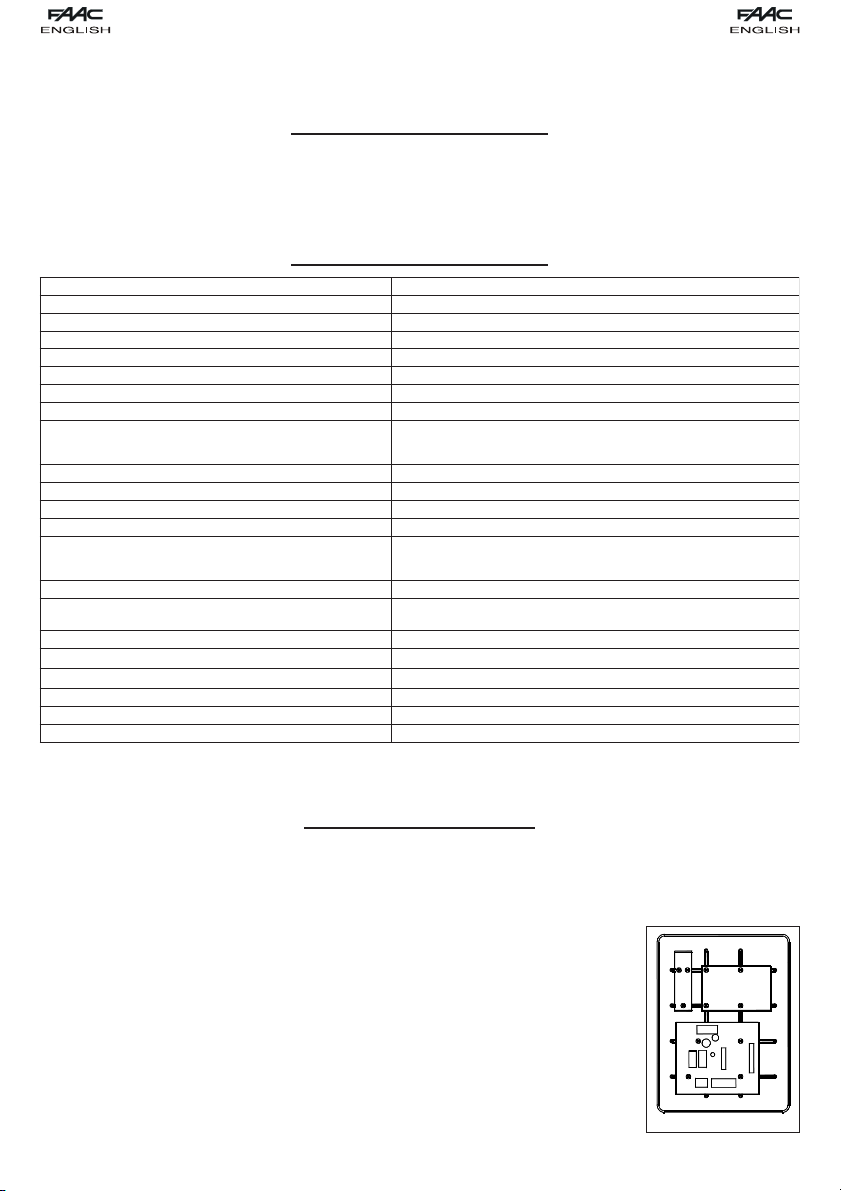
Procedure for securing components in the waterproof enclosure, referring to fig. 1:
1) Secure the support for the toroidal transformer in position A, using 3 Ø4.2x13 self-tapping screws (supplied),
placing the spacers between the support and the guides of the watertight enclosure.
NB.: the support is sized to house a transformer with the characteristics and dimensions specified on the
table in paragraph 2.
2) Secure the transformer to the support with 2 clamps (supplied).
3) If using buffer batteries, secure the relevant support in position B with 4 Ø3.5x9.5 self-tapping screws
(supplied) in the crossover holes of the guides of the watertight enclosure.
NB.: the support is sized to house 2 batteries (not supplied) with the characteristics and dimensions
specified on the table in paragraph 2.
$%
&
Fig. 1
10
3. PRELIMINARY SETTING-UP
Page 4

4) Position the batteries on the support.
5) Secure the control unit in position C with 4 Ø4.2x13 self-tapping screws (supplied), placing the spacers between the board and the
guides of the watertight enclosure.
4. CONNECTIONS AND OPERATION
4.1. TERMINAL BOARD M1
4.1.1 Open A
Terminals OPEN A - COM 2. Normally open contact. Connect, to these terminals, any device (push-button, key selector, etc.) that
commands total opening of the gate. The operation of this contact is defined by parameter D.
NB.:
An OPEN A pulse, total opening, always has priority on OPEN B, partial opening.
To install several pulse generators, connect the contacts in parallel.
4.1.2 Open B
Terminals OPEN B - COM 2. Normally open contact. Connect, to these terminals, any device (push-button, key selector, etc.) that must
command partial opening of the leaf. Partial opening is non-adjustable and equals 30% of the memory-stored total opening.
NB.:
An OPEN A pulse, total opening, always has priority on OPEN B, partial opening.
To install several pulse generators, connect the contacts in parallel.
4.1.3 STOP command
Terminals STOP - COM 2. Normally closed contact. Connect, to these terminals, any safety device (push-button, key selector, etc.) that
must stop gate movement. The status of this input is signalled by LED DL2 STOP.
NB.:
If no STOP devices are connected, jumper connect the input.
To install several STOP devices, connect the normally closed contacts in series.
4.1.4 Closing safety devices
Terminals FSW CL - COM 2. Normally closed contact. Connect, to these terminals, any safety device (photocells, safety edge, etc.) that
must control gate closing motion by reversing gate movement up to the maximum memory-stored opening. The status of this input is
signalled by LED DL3 FSW-CL.
NB.:
If no closing safety devices are connected to the closing motion, jumper connect the input.
To install several safety devices on the closing motion, connect the normally closed contacts in series.
4.1.5 Opening safety devices
Terminals FSW OP - COM 2. Normally closed contact. Connect, to these terminals, any safety device (photocells, safety edge, etc.) that
must control gate opening motion by stopping its movement. When the safety device is released, motion will resume normally, executing
the memory-stored cycle. The status of this input is signalled by LED DL4 FSW-OP.
NB.:
If no safety devices are connected to the opening motion, jumper connect the input:
To install several safety devices on the opening motion, connect the normally closed contacts in series.
4.2 M2 TERMINAL BOARD
4.2.1 Encoder
Terminals SIG. - -ENC - +ENC. Use the encoder supplied with the control unit. On the SIG terminal: connect the return signal from
encoder terminal S11; connect encoder terminal -12 to the -ENC terminal; connect encoder terminal +13 to terminal +ENC.
NB.:
The encoder must be used for operation of the control unit
For encoder operation, observe the connection between terminals as described above.
4.2.2 Closing limit switch (optional)
Terminals COMF - FCC. Normally closed contact. Connect the closing limit-switch, if any, to these terminals. The switch operates by
stopping the gate closing motion. The status of this input is signalled by LED DL5 FCC.
NB.:
If no closing limit-switch is used, the input must be jumper connected.
4.2.3 Opening limit switch (optional)
Terminals COMF - FCA. Normally closed contact. Connect the opening limit-switch, if any, to these terminals. The switch operates by
stopping the gate opening motion. The status of this input is signalled by LED DL6 FCA.
NB.:
If no opening limit-switch is used, the input must be jumper connected.
4.3 M3 TERMINAL BOARD
4.3.1 Flashing Lamp
Terminals LAMP - LAMP. Use a flashing-lamp with steady light (flashing is produced by the control unit) on operating voltage of 24 Vdc
15W max. It is recommended to connect the flashing lamp before programming the control unit, because its phases are displayed. A 1.5
sec. pre-flashing steady light goes on during both opening and closing. When the gate is open, the flashing-lamp is OFF, and only flashes
when the closing safety devices are engaged for a maximum time of 10 sec, signalling that one is operating in the gate movement area,
after which the flashing-lamp goes OFF even with the closing safety devices still engaged.
4.3.2 Motor
Terminals CHM1 - APM1. Connect, to these terminals, the motor with a power supply of 24Vdc 70W max.
4.4 TERMINAL BOARD M4
4.4.1 Power supply
Terminals VAC - VAC. Connect, to these terminals, the secondary winding wires arriving from the toroidal transformer with voltage of
22V~ 50 Hz. Power ON is indicated by the lighting up of LED DL1 POWER.
4.4.2 Batteries (optional)
Terminals +BAT - - BAT. Connect the 2 buffer batteries (optional) to these terminals. When the control unit is powered, it will keep the
batteries charged. The batteries come into operation when the transformer does not supply power.
11
Page 5

NB.:
For battery dimensions and characteristics, refer to the descriptions on the table in paragraph 2.
Power supply provided by the batteries should be considered an emergency situation. The number of possible manoeuvres depends
on the quality of the batteries, the gate's structure (weight, length, general conditions, etc.), and on the time since power was cut,
etc, etc.
Observe the battery supply polarity.
4.4.3 Accessories
Terminals +24 - -24. Output for power supply to 24Vdc outside accessories.
NB.:
Maximum load of accessories is 500 mA.
4.4.4 Earthing
An appropriate earthing terminal or cable. Earth connect the mains supplying 230V~.
NB.:
The connection is essential for correct operation of the control unit.
5. INSTALLING A RECEIVER CARD FOR REMOTE-CONTROL
The control unit is designed to house a 5-pin radio-receiver module. To install, cut out power and fit the module in the appropriate M5
connector inside the control unit.
ATTENTION: To avoid damaging the receiver and thus irreparably impairing its operation, the receiver must be installed while observing
the fitting direction specified in paragraph 12 (Connection lay-out).
This done, observe the radio-receiver instructions for memory-storing the remote control. When the remote control has been stored, it
controls START just like any command device.
6. CONTROL LEDS
DELNOFFO
1LD REWOP- remrofsnartybdeilppustinulortnoC
2LD POTS- evitcanidnammoC delbanednammoC
3LD LC-WSF- eerfecivedytefaS degagnesecivedytefaS
4LD PO-WSF- eerfecivedytefaS degagnesecivedytefaS
5LD CCF-eerfhctiwstimilgnisolC degagnehctiwstimilgnisolC
6LD ACF- eerfhctiwstimilgninepO degagnehctiwstimilgninepO
NB.:
Indicated in bold: status of LEDs with the gate closed, control unit supplied by transformer, and limit-switches connected.
If the limit-switches are not used, the relevant contacts must be jumper connected and the DL5 and DL6 LEDs must always be ON.
seirettabreffubehtyb
7. OPERATION OF DISPLAY
The control unit has a handy display for viewing and programming the operating parameters. Furthermore, it constantly shows gate status
during normal operation.
When parameters are being displayed and adjusted, the display shows the selected parameter on the
left, and the relevant value on the right. Fig. 2 shows a display example of parameter A at value 2.
deilppustinulortnocro,deilppusrewopoN
Fig. 2
During normal operation, the display shows gate status. The displayed values are indicated on the following table:
EULAVYALPSID SUTATSETAG
tsertaetaG
gninepoetaG
.)hpargaraptxenees-delbaneerusolc-ercitamotuahtiwylnO(sutatsesuapninepoetaG
gnisolcetaG
During programming, the display shows value for the whole time.
8. ADJUSTING THE OPERATING PARAMETERS
When you have made all the necessary connections, power up the system and check if all the signalling LEDs are in the condition
specified in paragraph 6.
To access parameter adjustment, follow the instructions below:
Display shows value .
Press and hold down key P2 until the display shows the name of the first parameter.
Press push-button P1 to change the value of the parameter.
To move on to the next parameter, press push-button P2 again..
When 60 seconds have elapsed without any key being touched, the control unit exits the adjustment mode. You can manually exit
the adjustment mode by scrolling all the parameters. When the displays show , you have returned to normal operation.
The following table summarises the different parameters and the assignable values.
12
Page 6

YALPSID NOITPIRCSED
ecrofrotomwoL
ecrofrotomwol-muideM
ecrofrotomhgih-muideM
ecrofrotomhgiH
:erusolc-ercitamotuA .gnisolcetagcitamotuaselbasidroselbanenoitcnufsiht
delbasiD
delbanE
:dnammocANEPOfonoitarepO .nottub-hsup)gninepolatot(ANEPOehtforuoivahebehtsenimretednoitcnufsiht
snepO/sesolC/snepO
spotS/sesolC/spotS/snepO
:gnisolcretfaekortsgnisreveR swollasihT.gnisolcretfa,ekortsgninepostiflahtuobatceffelliwetageht,delbanesinoitcnufsihtfi
delbasiD
delbanE
:noitcnufodnoC .detibihnisidnammocnepoeht,denepogniebsietagehtelihwdelbanesinoitcnufsihtfi
delbasiD
delbanE
.seulav
.seulavowt
woL
hgiH
:egatnecreptniopnoitareleceD tesowtehtmorftignitceles,noitcesdetarelecedehtfohtgnelehttesotdesusiretemarapsiht
gninepoderots-yromemmumixamfo%02
gninepoderots-yromemmumixamfo%01
:esahpdetarelecedgniruddeepS ehtmorftignitceles,esahpdetarelecedehtgniruddeepsrotomtesotdesusiretemarapsiht
ylnoredocnehtiW
hctiws-timildnaredocnE
.ecrofrotomdnahctulccinortcelefotnemtsujdaytivitisneS
.noitarepoelbissopstignitatilicaf,ecivedesaelerehteveilerot
.desugnieboslaerasehctiws-timilehtfiylnodelbaneebtsumnoitcnufsiht:sehctiwstimilhtiwnoitarepO
During the programming procedure, the control unit memory-stores the mechanical stop points during opening, closing, and any
pause time. To carry out the programming procedure, follow these instructions:
Release the gearmotor, take the gate to halfway its opening stroke, and them re-lock the gearmotor.
Power up the control unit and check if value is shown on the display.
Hold down key P2 for about 5 seconds - the control unit shows the value of the first parameter.
Give an OPEN A pulse, using a push-button and any other device commanding total gate opening, the display shows value , and
the gate begins a closing manoeuvre up to the mechanical closing stop, or up to the closing limit-switch, if supplied and enabled (see
previous paragraph).
Attention: if, during programming, the operator's first manoeuvre is opening, cut power and change over the wires connected to
terminals CHM1 - APM1. Repeat the programming procedure from the first point.
After a pause of about 2 seconds, the gate carries out a total opening either up to the opening mechanical stop point or to the relevant
limit-switch.
If automatic closing is not enabled, this means programming has finished and the display shows value . Vice versa, the control
unit begins counting pause time.
When the required time has elapsed, give another OPEN A command, and the gate will begin to close.
When closing has finished, programming has terminated too, and the display shows value .
13
9. PROGRAMMING
Page 7

N.B.:
The display shows value during the entire programming procedure.
The flashing lamp stays lighted on a steady light during the entire programming time.
Gate motion is decelerated during programming.
10. OPERATION OF ELECTRONIC CLUTCH
A very important device for reasons of safety. Its setting stays unchanged long-term, without wear or any setting changes.
It is active during both closing and opening. When it operates, it reverses movement without disabling automatic closing if enabled.
If it operates twice consecutively, it goes into STOP status, disabling any automatic command. This is because, as the clutch operates
twice, it means that the obstacle remains and it could be dangerous to perform any further manoeuvre, therefore forcing the user to give
an opening or closing command.
If the clutch operates for more than 90 consecutive seconds, the control unit performs an EMERGENCY procedure and will carry out a
complete opening in decelerated mode up to the opening stop-point, and then will close automatically so that stop-points are
independently re-synchronised.
11. PROTECTION FUSES
ESUFNOITCETORPESUFNOITCETORPESUFNOITCETORP
02x5-V052/A01T=1FV22ylppusrewoP
-V052/A5.0T=2F
02x5
otylppuS
dnaseirossecca
regrahc-yrettab
-V052/A5.0R=3F
02x5
pmalgnihsalF
tuptuo
12. CONNECTION LAY-OUT
&2'
3
',63/$<
3
5(6(7
)$
32:(5
'/-03
5HFHLYHUFRQQHFWRU
5HFHLYHU
2WKHURSHQLQJVDIHW\GHYLFHV
Other closing safety devices
2WKHUFORVLQJVDIHW\GHYLFHV
Other opening safety devices
&ORVLQJSKRWRFHOOV
2SHQLQJDQGFORVLQJSKRWRFHOOV
2SHQLQJSKRWRFHOOV
1
(
$
3
2
5;&/
7;23&/
5;23
)$
0
)6:
)6:
6723
23
&/
/
/
/
'
'
'
1
(
3
2
0
3
%
2
7
6
)6:
2
3
/
*
,
&
&
2
6
0
)&$
)&&
'/
'/
)
&
&
0
&
1
1
2
(
&
(
&
)
0
3
3
0
$
&
)
0
0
0
+
3
$
$
$
/
/
&
0
7
&
&
$
$
$
%
9
9
0
9a
0
0RWRU
9a
+]
7RURLGDO
WUDQVIRUPHU
7;&/
7;23&/
7;23
(QFRGHU
)ODVKLQJODPS
2WKHURSHQLQJDQG
FORVLQJVDIHW\GHYLFHV
)$
7
9
9
$
%
3RZHUVXSSO\IRU
H[WHUQDODFFHVVRULHV
%DWWHULHV
(DUWKLQJ
14
Page 8

emitesuaptesnehwsesolc
no,dnagnisolc-erselbasiD
sahemitesuapfisdnoces
-erti,asrev-eciV.despale
5retfasesolc-er,esaeler
dnanoitarepospotS
dnanoitarepospotS
esaelernosesrever
despalesah
esaelernosemuser
emitesuaptesnehwsesolc
no,dnagnisolc-erselbasiD
sahemitesuapfisdnoces
-erti,asrev-eciV.despale
5retfasesolc-er,esaeler
dnanoitarepospotS
dnanoitarepospotS
esaelernosesrever
despalesah
esaelernosemuser
13. FUNCTION LOGICS
emitesuaptesnehwsesolc
no,dnagnisolc-erselbasiD
sahemitesuapfisdnoces
-erti,asrev-eciV.despale
5retfasesolc-er,esaeler
despalesah
sdnammocNEPOselbasiDtceffeoNsdnammocNEPOselbasiD
0=F0=d1=Ccigol"A"citamotuA
)delbasidNEPO(
tceffeoN
gninepolaitrapfaelsetucexE
esuapretfasesolc-erdna
noitarepospotStceffeoN
etagehtsesolc-eR
yletaidemmi
emit
tceffeoN
dnanoitarepospotS
esaelernosemuser
0=F1=d1=Ccigol"PA"citamotuAdeppetS
sdnammocNEPOselbasiDtceffeoNsdnammocNEPOselbasiD
)delbasidNEPO(
tceffeoN
gninepolaitrapfaelsetucexE
esuapretfasesolc-erdna
emit
emitesuaptesnehwsesolc
no,dnagnisolc-erselbasiD
sahemitesuapfisdnoces
-erti,asrev-eciV.despale
5retfasesolc-er,esaeler
despalesah
noitarepospotStceffeoN
etagehtsesolc-eR
yletaidemmi
tceffeoN
dnanoitarepospotS
esaelernosemuser
tceffeoNnoitarepospotStceffeoNnoitomsesreveR
tceffeoNnoitarepospotS
-erdnafaelehtsnepO
emitesuapretfasesolc
AnepOBnepOpotSsecivedytefasgninepOsecivedytefasgnisolCecivedytefasLC/PO
sutatsetaG sesluP
desolC
esuapnonepO emitesuapsdaoleR
gninepO noitometagsesreveRtceffeoNnoitarepospotS
gnisolC noitometagsesreveRtceffeoNnoitarepospotStceffeoNnoitomsesreveR
sutatsetaG sesluP
-erdnafaelehtsnepO
emitesuapretfasesolc
AnepOBnepOpotSsecivedytefasgninepOsecivedytefasgnisolCecivedytefasLC/PO
desolC
dnanoitometagspotS
dnanoitometagspotS
esluptxennosnepo
esluptxennosesolc
esuapnonepO emitesuapsdaoleR
gninepO
gnisolC
15
Page 9

ti,asrev-eciV.despalesah
sesolc-er,esaelerno,dna
dnammocNEPOselbasiD
dnanoitarepospotS
dnanoitarepospotS
esaelernosemuser
esaelernosesrever
..ces5retfa
tceffeoN
sesolc-er,esaelerno,dna
dnammocNEPOselbasiD
dnanoitarepospotS
dnanoitarepospotS
esaelernosesrever
..ces5retfa
esaelernosemuser
tceffeoN
retfasesolc-er,esaelerno
,dnagnisolc-erselbasiD
esuaptesnehwsesolc-er
emitesuapfisdnoces5
retfasesolc-er,esaelerno
,dnagnisolc-erselbasiD
emitesuapfisdnoces5
dnanoitarepospotS
dnanoitarepospotS
esaelernosesrever
despalesahemit
ti,asrev-eciV.despalesah
esuaptesnehwsesolc-er
despalesahemit
esaelernosemuser
tceffeoN
sdnammocNEPOselbasiDtceffeoNsdnammocNEPOselbasiD
sdnammocNEPOselbasiDdnammocNEPOselbasiD
0=F0=d0=Ccigol"E"citamotua-imeS
)delbasidNEPO(
)delbasidNEPO(
tceffeoN
tceffeoN
AnepOBnepOpotSsecivedytefasgninepOsecivedytefasgnisolCecivedytefasLC/PO
dnanoitarepospotS
esaelernosemuser
0=F1=d0=Ccigol"PE"citamotua-imeSdeppetS
sdnammocNEPOselbasiDtceffeoNsdnammocNEPOselbasiD
sdnammocNEPOselbasiDdnammocNEPOselbasiD
)delbasidNEPO(
)delbasidNEPO(
tceffeoN
tceffeoN
AnepOBnepOpotSsecivedytefasgninepOsecivedytefasgnisolCecivedytefasLC/PO
dnanoitarepospotS
esaelernosemuser
1=F0=d1=Ccigol"D"odnoC
tceffeoNnoitarepospotStceffeoNnoitometagsesreveR
tceffeoNnoitarepospotS
dnanoitarepoetagspotS
dnanoitometagspotS
esluptxennosnepo
esluptxennosesolc
sdnammocNEPOselbasiDtceffeoNsdnammocNEPOselbasiD
)delbasidNEPO(
tceffeoN
sesolc-erdnagninepo
laitrapfaelsetucexE
-erdnafaelehtsnepO
emitesuapretfasesolc
AnepOBnepOpotSsecivedytefasgninepOsecivedytefasgnisolCecivedytefasLC/PO
noitarepospotStceffeoN
etagehtsesolc-eR
emitesuapretfa
yletaidemmi
dnanoitarepospotS
esaelernosemuser
sutatsetaG sesluP
desolC faelehtsnepOgninepolaitrapsetucexE
gnisolC noitometagsesreveRtceffeoNnoitarepospotStceffeoNnoitometagsesreveR
nepO sesolCetagehtsesolC
sutatsetaG sesluP
gninepO noitometagsesreveRtceffeoNnoitarepospotS
desolC faelehtsnepOgninepolaitrapsetucexE
gnisolC
nepO sesolCetagehtsesolC
sutatsetaG sesluP
gninepO
desolC
esuapnonepO emitesuapsdaoleR
gninepO tceffeoNtceffeoNnoitarepospotS
gnisolC noitometagsesreveRtceffeoNnoitarepospotStceffeoNnoitomsesreveR
16
Page 10

Le descrizioni e le illustrazioni del presente manuale non sono impegnative. La FAAC si riserva il diritto, lasciando
inalterate le caratteristiche essenziali dell’apparecchiatura, di apportare in qualunque momento e senza
impegnarsi ad aggiornare la presente pubblicazione, le modifiche che essa ritiene convenienti per miglioramenti
tecnici o per qualsiasi altra esigenza di carattere costruttivo o commerciale.
The descriptions and illustrations contained in the present manual are not binding. FAAC reserves the right, whilst
leaving the main features of the equipments unaltered, to undertake any modifications it holds necessary for either
technical or commercial reasons, at any time and without revising the present publication.
Les descriptions et les illustrations du présent manuel sont fournies à titre indicatif. FAAC se réserve le droit
d’apporter à tout moment les modifications qu’elle jugera utiles sur ce produit tout en conservant les caractéristiques
essentielles, sans devoir pour autant mettre à jour cette publication.
Die Beschreibungen und Abbildungen in vorliegendem Handbuch sind unverbindlich. FAAC behält sich das Recht
vor, ohne die wesentlichen Eigenschaften dieses Gerätes zu verändern und ohne Verbindlichkeiten in Bezug auf
die Neufassung der vorliegenden Anleitungen, technisch bzw. konstruktiv/kommerziell bedingte Verbesserungen
vorzunehmen.
Las descripciones y las ilustraciones de este manual no comportan compromiso alguno. FAAC se reserva el
derecho, dejando inmutadas las características esenciales de los aparatos, de aportar, en cualquier momento
y sin comprometerse a poner al día la presente publicación, todas las modificaciones que considere oportunas
para el perfeccionamiento técnico o para cualquier otro tipo de exigencia de carácter constructivo o comercial.
De beschrijvingen in deze handleiding zijn niet bindend. FAAC behoudt zich het recht voor op elk willekeurig
moment de veranderingen aan te brengen die het bedrijf nuttig acht met het oog op technische verbeteringen
of alle mogelijke andere productie- of commerciële eisen, waarbij de fundamentele eigenschappen van de
apparaat gehandhaafd blijven, zonder zich daardoor te verplichten deze publicatie bij te werken.
FAAC per la natura
• La presente istruzione è realizzata al 100% in carta riciclata.
• Non disperdete nell'ambiente gli imballaggi dei componenti dell'automazione bensì selezionate
i vari materiali (es. cartone, polistirolo) secondo prescrizioni locali per lo smaltimento rifiuti e le
norme vigenti.
FAAC for the environment
• The present manual is produced in 100% recycled paper
• Respect the environment. Dispose of each type of product packaging material (card, polystyrene)
in accordance with the provisions for waste disposal as specified in the country of installation.
FAAC écologique
• La présente notice a été réalisée 100% avec du papier recyclé.
• Ne pas jeter dans la nature les emballages des composants de l’automatisme, mais sélectionner
les différents matériaux (ex.: carton, polystyrène) selon la législation locale pour l’élimination des
déchets et les normes en vigueur.
FAAC der Umwelt zuliebe
• Vorliegende Anleitungen sind auf 100% Altpapier gedruckt.
• Verpackungsstoffe der Antriebskomponenten (z.B. Pappe, Styropor) nach den einschlägigen
Normen der Abfallwirtschaft sortenrein sammeln.
FAAC por la naturaleza.
• El presente manual de instrucciones se ha realizado, al 100%, en papel reciclado.
• Los materiales utilizados para el embalaje de las distintas partes del sistema automático (cartón,
poliestireno) no deben tirarse al medio ambiente, sino seleccionarse conforme a las prescripciones
locales y las normas vigentes para el desecho de residuos sólidos.
FAAC voor de natuur
• Deze gebruiksaanwijzing is gedrukt op 100% kringlooppapier.
• Laat de verpakkingen van de componenten van het automatische systeem niet in het milieu
achter, maar scheidt de verschillende materialen (b.v. karton, polystyreen) volgens de plaatselijke
voorschriften op de afvalverwerkingen en de geldende normen.
voor de natuur
100% kringlooppapier
para la naturaleza
100% papel reciclado
ist umweltfreundlich
100% Altpapier
pour la nature
papier recyclé 100%
FAAC S.p.A.
Via Benini, 1
40069 Zola Predosa (BO) - ITALIA
Tel.: 051/61724 - Fax: 051/758518
www.faacgroup.com
Timbro del Rivenditore:/Distributor’s Stamp:/Timbre de l’Agent:/ Fachhändlerstempel:/Sello del Revendedor:/Stempel van de dealer:
for nature
recycled paper 100%
per la natura
carta riciclata 100%
732489 - Rev. A -
 Loading...