


 Loading...
User Guide
Switchers
MPS 409
Media Presentation Switcher
68-1833-01 Rev. A
07 10

Precautions
Safety Instructions • English
This symbol is intended to alert the user of important operating and maintenance (servicing) instructions in the literature provided with the equipment.
This symbol is intended to alert the user of the presence of uninsulated dangerous voltage within the product’s enclosure that may present a risk of electric shock.
Caution
Read Instructions • Read and understand all safety and operating instructions before using the equipment. Retain Instructions • The safety instructions should be kept for future reference.
Follow Warnings • Follow all warnings and instructions marked on the equipment or in the user information.
Avoid Attachments • Do not use tools or attachments that are not recommended by the equipment manufacturer because they may be hazardous.
Consignes de Sécurité • Français
Ce symbole sert à avertir l’utilisateur que la documentation fournie avec le matériel contient des instructions importantes concernant l’exploitation et la maintenance (réparation).
Ce symbole sert à avertir l’utilisateur de la présence dans le boîtier de l’appareil de tensions dangereuses non isolées posant des risques d’électrocution.
Attention
Lire les instructions• Prendre connaissance de toutes les consignes de sécurité et d’exploitation avant d’utiliser le matériel.
Conserver les instructions• Ranger les consignes de sécurité afin de pouvoir les consulter à l’avenir.
Respecter les avertissements • Observer tous les avertissements et consignes marqués sur le matériel ou présentés dans la documentation utilisateur.
Sicherheitsanleitungen • Deutsch
Dieses Symbol soll dem Benutzer in der im Lieferumfang enthaltenen Dokumentation besonders wichtige Hinweise zur Bedienung und Wartung (Instandhaltung) geben.
Dieses Symbol soll den Benutzer darauf aufmerksam machen, daß im Inneren des Gehäuses dieses Produktes gefährliche Spannungen, die nicht isoliert sind und die einen elektrischen Schock verursachen können, herrschen.
Achtung
Lesen der Anleitungen • Bevor Sie das Gerät zum ersten Mal verwenden, sollten Sie alle Sicherheits-und Bedienungsanleitungen genau durchlesen und verstehen.
Aufbewahren der Anleitungen • Die Hinweise zur elektrischen Sicherheit des Produktes sollten Sie aufbewahren, damit Sie im Bedarfsfall darauf zurückgreifen können.
Befolgen der Warnhinweise • Befolgen Sie alle Warnhinweise und Anleitungen auf dem Gerät oder in der Benutzerdokumentation.
Keine Zusatzgeräte • Verwenden Sie keine Werkzeuge oder Zusatzgeräte, die nicht ausdrücklich vom Hersteller empfohlen wurden, da diese eine Gefahrenquelle darstellen können.
Instrucciones de seguridad • Español
Este símbolo se utiliza para advertir al usuario sobre instrucciones importantes de operación y mantenimiento (o cambio de partes) que se desean destacar en el contenido de la documentación suministrada con los equipos.
Este símbolo se utiliza para advertir al usuario sobre la presencia de elementos con voltaje peligroso sin protección aislante, que puedan encontrarse dentro de la caja o alojamiento del producto, y que puedan representar riesgo de electrocución.
Precaucion
Leer las instrucciones • Leer y analizar todas las instrucciones de operación y seguridad, antes de usar el equipo.
Conservar las instrucciones • Conservar las instrucciones de seguridad para futura consulta.
Obedecer las advertencias • Todas las advertencias e instrucciones marcadas en el equipo o en la documentación del usuario, deben ser obedecidas.
•


••
••
Warning
Power sources • This equipment should be operated only from the power source indicated on the product. This equipment is intended to be used with a main power system with a grounded (neutral) conductor. The third (grounding) pin is a safety feature, do not attempt to bypass or disable it.
Power disconnection • To remove power from the equipment safely, remove all power cords from the rear of the equipment, or the desktop power module (if detachable), or from the power source receptacle (wall plug).
Power cord protection • Power cords should be routed so that they are not likely to be stepped on or pinched by items placed upon or against them.
Servicing • Refer all servicing to qualified service personnel. There are no user-serviceable parts inside. To prevent the risk of shock, do not attempt to service this equipment yourself because opening or removing covers may expose you to dangerous voltage or other hazards.
Slots and openings • If the equipment has slots or holes in the enclosure, these are provided to prevent overheating of sensitive components inside. These openings must never be blocked by other objects.
Lithium battery • There is a danger of explosion if battery is incorrectly replaced. Replace it only with the same or equivalent type recommended by the manufacturer. Dispose of used batteries according to the manufacturer’s instructions.
Eviter les pièces de fixation • Ne pas utiliser de pièces de fixation ni d’outils non recommandés par le fabricant du matériel car cela risquerait de poser certains dangers.
Avertissement
Alimentations • Ne faire fonctionner ce matériel qu’avec la source d’alimentation indiquée sur l’appareil. Ce matériel doit être utilisé avec une alimentation principale comportant un fil de terre (neutre). Le troisième contact (de mise à la terre) constitue un dispositif de sécurité : n’essayez pas de la contourner ni de la désactiver.
Déconnexion de l’alimentation• Pour mettre le matériel hors tension sans danger, déconnectez tous les cordons d’alimentation de l’arrière de l’appareil ou du module d’alimentation de bureau (s’il est amovible) ou encore de la prise secteur.
Protection du cordon d’alimentation • Acheminer les cordons d’alimentation de manière à ce que personne ne risque de marcher dessus et à ce qu’ils ne soient pas écrasés ou pincés par des objets.
Réparation-maintenance • Faire exécuter toutes les interventions de réparation-maintenance par un technicien qualifié. Aucun des éléments internes ne peut être réparé par l’utilisateur. Afin d’éviter tout danger d’électrocution, l’utilisateur ne doit pas essayer de procéder lui-même à ces opérations car l’ouverture ou le retrait des couvercles risquent de l’exposer à de hautes tensions et autres dangers.
Fentes et orifices • Si le boîtier de l’appareil comporte des fentes ou des orifices, ceux-ci servent à empêcher les composants internes sensibles de surchauffer. Ces ouvertures ne doivent jamais être bloquées par des objets.
Lithium Batterie • Il a danger d’explosion s’ll y a remplacment incorrect de la batterie. Remplacer uniquement avec une batterie du meme type ou d’un ype equivalent recommande par le constructeur. Mettre au reut les batteries usagees conformement aux instructions du fabricant.
Vorsicht
Stromquellen • Dieses Gerät sollte nur über die auf dem Produkt angegebene Stromquelle betrieben werden. Dieses Gerät wurde für eine Verwendung mit einer Hauptstromleitung mit einem geerdeten (neutralen) Leiter konzipiert. Der dritte Kontakt ist für einen Erdanschluß, und stellt eine Sicherheitsfunktion dar. Diese sollte nicht umgangen oder außer Betrieb gesetzt werden.
Stromunterbrechung • Um das Gerät auf sichere Weise vom Netz zu trennen, sollten Sie alle Netzkabel aus der Rückseite des Gerätes, aus der externen Stomversorgung (falls dies möglich ist) oder aus der Wandsteckdose ziehen.
Schutz des Netzkabels • Netzkabel sollten stets so verlegt werden, daß sie nicht im Weg liegen und niemand darauf treten kann oder Objekte daraufoder unmittelbar dagegengestellt werden können.
Wartung • Alle Wartungsmaßnahmen sollten nur von qualifiziertem Servicepersonal durchgeführt werden. Die internen Komponenten des Gerätes sind wartungsfrei. Zur Vermeidung eines elektrischen Schocks
versuchen Sie in keinem Fall, dieses Gerät selbst öffnen, da beim Entfernen der Abdeckungen die Gefahr eines elektrischen Schlags und/oder andere Gefahren bestehen.
Schlitze und Öffnungen • Wenn das Gerät Schlitze oder Löcher im Gehäuse aufweist, dienen diese zur Vermeidung einer Überhitzung der empfindlichen Teile im Inneren. Diese Öffnungen dürfen niemals von anderen Objekten blockiert werden.
Litium-Batterie • Explosionsgefahr, falls die Batterie nicht richtig ersetzt wird. Ersetzen Sie verbrauchte Batterien nur durch den gleichen oder einen vergleichbaren Batterietyp, der auch vom Hersteller empfohlen wird. Entsorgen Sie verbrauchte Batterien bitte gemäß den Herstelleranweisungen.
Evitar el uso de accesorios • No usar herramientas o accesorios que no sean especificamente recomendados por el fabricante, ya que podrian implicar riesgos.
Advertencia
Alimentación eléctrica • Este equipo debe conectarse únicamente a la fuente/tipo de alimentación eléctrica indicada en el mismo. La alimentación eléctrica de este equipo debe provenir de un sistema de distribución general con conductor neutro a tierra. La tercera pata (puesta a tierra) es una medida de seguridad, no puentearia ni eliminaria.
Desconexión de alimentación eléctrica • Para desconectar con seguridad la acometida de alimentación eléctrica al equipo, desenchufar todos los cables de alimentación en el panel trasero del equipo, o desenchufar el módulo de alimentación (si fuera independiente), o desenchufar el cable del receptáculo de la pared.
Protección del cables de alimentación • Los cables de alimentación eléctrica se deben instalar en lugares donde no sean pisados ni apretados por objetos que se puedan apoyar sobre ellos.
Reparaciones/mantenimiento • Solicitar siempre los servicios técnicos de personal calificado. En el interior no hay partes a las que el usuario deba acceder. Para evitar riesgo de electrocución, no intentar personalmente la reparación/mantenimiento de este equipo, ya que al abrir o extraer las tapas puede quedar expuesto a voltajes peligrosos u otros riesgos.
Ranuras y aberturas • Si el equipo posee ranuras o orificios en su caja/alojamiento, es para evitar el sobrecalientamiento de componentes internos sensibles. Estas aberturas nunca se deben obstruir con otros objetos.
Batería de litio • Existe riesgo de explosión si esta batería se coloca en la posición incorrecta. Cambiar esta batería únicamente con el mismo tipo (o su equivalente) recomendado por el fabricante. Desachar las baterías usadas siguiendo las instrucciones del fabricante.
•
•
•
•
•
•

FCC Class A Notice
This equipment has been tested and found to comply with the limits for a Class A digital device, pursuant to part 15 of the FCC Rules. Operation is subject to the following two conditions:
1.This device may not cause harmful interference.
2.This device must accept any interference received, including interference that may cause undesired operation.
The Class A limits are designed to provide reasonable protection against harmful interference when the equipment is operated in a commercial environment. This equipment generates, uses, and can radiate radio frequency energy and, if not installed and used in accordance with the instruction manual, may cause harmful interference to radio communications. Operation of this equipment in a residential area is likely to cause harmful interference, in which case the user will be required to correct the interference at his own expense.
NOTE: This unit was tested with shielded cables on the peripheral devices. Shielded cables must be used with the |
unit to ensure compliance with FCC emissions limits. |
Notes, Tips, Cautions, and Warnings
 NOTE: Notes call attention to information that may be of special importance.
 TIP: Tips provide technical information that may be helpful during
installation, for performing a procedure or adjustment, or in the operation of the USB Extenders.
CAUTION: Indicates a potential hazard to equipment or data may exist.
 WARNING: Indicates a potential hazard to personal safety exists.
Copyright
© 2010 Extron Electronics. All rights reserved.
Trademarks
All trademarks mentioned in this manual are the properties of their respective owners.


Contents |
|
Introduction ............................................ |
1 |
About this Manual........................................... |
1 |
About the MPS 409.......................................... |
1 |
Features........................................................... |
1 |
Installation .............................................. |
4 |
Mounting the Switcher..................................... |
4 |
UL Rack Mounting Guidelines....................... |
4 |
Rear Panel Connections.................................... |
6 |
Cabling the MPS 409 Switcher......................... |
9 |
Operation ............................................... |
10 |
Front Panel Features....................................... |
10 |
Video/Audio Group Buttons........................ |
10 |
Microphone and Program Audio Controls... |
11 |
Switcher Mode Control............................... |
11 |
Front Panel Operation..................................... |
12 |
Switcher Operating Modes......................... |
12 |
View Mode................................................. |
12 |
Input Selection — Single Switcher Mode.... |
13 |
Input Selection — Separate Switcher |
|
Mode........................................................ |
13 |
Program Audio Breakaway.......................... |
13 |
Combine Mode.......................................... |
14 |
Front Panel Security Lockout....................... |
14 |
Program Audio............................................... |
15 |
Program Audio Selection............................ |
15 |
Program Audio Breakaway.......................... |
15 |
Program Audio Volume Control .............. |
15 |
Program Audio Mute.................................. |
15 |
Audio Gain and Attenuation Adjustments.. 16 |
|
Microphone Controls.................................. |
17 |
EDID Minder................................................... |
18 |
HDCP............................................................. |
19 |
SIS Programming and Control .............. |
20 |
Connection Options....................................... |
20 |
Remote Control Port (RS-232)..................... |
20 |
USB Configuration Port.............................. |
21 |
Host-to-MPS Communications........................ |
21 |
MPS Switcher-initiated Messages................ |
21 |
MPS Switcher Error Responses.................... |
21 |
Command/Response Table.............................. |
22 |
Using the Command/Response Table.......... |
22 |
Updating Firmware......................................... |
28 |
Reference Information .......................... |
29 |
Specifications................................................. |
29 |
Part Numbers and Accessories........................ |
34 |
Included Parts............................................. |
34 |
Optional Accessories................................... |
34 |
Cables and Connectors................................... |
35 |
Pre-cut Cables............................................ |
35 |
Bulk Cable.................................................. |
35 |
Assorted Connectors.................................. |
36 |
MPS 409 Switcher • Contents |
v |

MPS 409 Switcher • Contents |
vi |

Introduction
•About this User Guide
•About the MPS 409
•Features
About this User Guide
This guide contains information to install, configure, and operate the Extron Electronics
MPS 409, Media Presentation Switcher.
In this guide, the MPS 409 may be referred to as “MPS”, “MPS 409” or “switcher”.
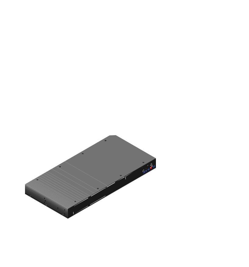
About the MPS 409
The Extron MPS 409 is a multi video format Media Presentation Switcher for small presentation systems. The MPS 409 integrates several video switchers into one product. The MPS 409 is a 2x1 VGA and audio switcher, a 2x1 DVI-D video and audio switcher, a 3x1 HDMI and audio switcher, and a 2x1 composite video and audio switcher. The MPS 409 can also function as a 9x1 video switcher and includes a mic/line input with phantom power, mic audio ducking (talkover), executive front panel lockout, and a program audio output. In addition it has the ability to combine DVI & HDMI inputs to create a 5x1 DVI/HDMI video and audio switcher. The switcher includes EDID Minder® and provides HDCP compliance.
Features
•Multiple video inputs — Nine inputs include two VGA (or SVGA, UXGA, RGBHV, RGBS, RGsB, or RsGsBs) inputs on 15-pin HD female connectors, two DVI (DVI-D only), three HDMI, and two composite video.
•Multiple video outputs — Four outputs for simultaneous (in Separate mode), or one at a time (in Single mode) display on VGA, DVI, HDMI, or composite video devices.
•EDID Minder — Automatically manages EDID – Extended Display Identification Data communication between the display and connected DVI, and VGA input sources. EDID Minder ensures that all sources power up correctly, whether or not they are actively connected to the display device through the switcher output.
•HDCP compliance — Ensures display of content protected media and interoperability with other HDCP compliant devices.
•Multiple audio inputs — Seven 3.5 mm female stereo input connectors include two in the VGA group, two in the DVI group, and three in the HDMI group corresponding to the video inputs. The composite video group includes two stereo RCA inputs corresponding to the two composite video inputs.
•Multiple audio outputs — One 3.5 mm stereo output for each VGA, DVI, and HDMI group, and one stereo RCA output for the composite video group, plus one 5-pole captive screw connector for Program Audio Out.
MPS 409 • Introduction |
1 |

•Program audio switcher — A four input, one output stereo audio switcher allows the audio input of any video group to be selected for the program audio output, with volume and mute control. The MPS 409 features balanced/unbalanced program audio output on a 5-pole captive screw connector.
•Microphone/line input — One 3.5 mm captive screw connector is used for a balanced/unbalanced Mic or Line level input. The input has an adjustment range of -66 dB to +12 dB. The microphone input includes a Mute button for "talk over", with adjustable threshold and volume control.
•Front panel security lockout (Executive mode) — Prevents unauthorized use in non-secure environments. Locks out all front panel functions except input selection and program volume control to prevent unauthorized changes.
•RS-232 remote control — A rear panel RS-232 port enables control via a control system. Extron Electronics Simple Instruction Set™ (SIS™) allows for quick and easy programming.
•Rack-mountable — The 1U high, full rack width, metal enclosure is rack mountable, with supplied rack mounting brackets.
•Multiple switcher modes — Multiple switcher modes provide flexible signal routing capabilities to address the varying system switching environments. Users can choose among four switcher modes: Single, Separate, Single-combine, and Separate combine.
оо Single switcher mode — Allows one-touch switching. When one of the nine inputs is selected, video and associated audio input signals are routed to the outputs of its group; the selected audio is also routed to the program audio output. In this mode, outputs of the other groups are muted.
оо Separate switcher mode — Allows independent switching of any given group. This effectively segregates switching operations so that the MPS 409 becomes four separate video switchers. While operating in separate switcher mode the program audio can be output from any group, while cueing up for another group, without interruption.
оо Combine switcher mode – Allows up to five HDMI and DVI source devices to be routed to a single HDMI-enabled digital display. Audio from the corresponding digital input, connected through the 3.5 mm stereo jack, is routed to the local and
program audio outputs. This mode can be used when the switcher is in Separate or Single switcher mode.
•Front-panel Mic and Program Audio output volume controls — To streamline audio setup, the MPS 409 features front-panel Mic and program audio output volume controls which allow for easy and separate adjustment of Mic and program audio volumes. This eliminates the need for audio preamplifiers in many system designs.
•Audio input gain and attenuation — Allows users to set the level of audio gain and attenuation for each input channel so that there are no noticeable volume differences when switching between sources.
•Mic talk over — The talk over feature automatically reduces program audio when it detects a microphone signal. This eliminates the need for a separate stand-alone audio ducking processor. The talk over level is adjustable via the RS-232 control.
•HDMI 1.3 compatible — Supports HDMI 1.3 specification features, including data rates up to 6.75 Gbps, deep color, auto-lip sync, and HD lossless audio formats.
•Audio breakaway — Provides the capability to break an audio signal away from its corresponding video signal and route to the program audio output, allowing the audio channels to be operated as a separate switcher.
MPS 409 • Introduction |
2 |
•+48V phantom microphone power — Powers a condenser microphone.
•Provides +5 VDC, 250 mA power on the HDMI and DVI outputs for external peripheral devices
•Internal universal power supply — The 100-240 VAC, 50-60 Hz, international power supply provides worldwide power compatibility.
|
|
Extron |
|
|
MLC 226 IP |
|
|
Y |
|
|
DISPLA |
|
|
Composite |
Projector |
HDMI |
Microphone |
DVI |
|
|
|
|
|
|
VGA |
|
|
|
RS-232 |
|
M |
PROGRA |
|
AUDI |
R- |
OUT |
|
+ |
|
L - |
|
+ |
|
R
Extron
SI 28
Surface-mount
Speakers
|
|
|
Composite |
Extron |
Extron |
|
|
|
|
|
|
|
XPA 1002 |
|
MPS 409 |
|
|
|
Power |
Digital Media |
DVI |
HDMI |
Document |
Ampli er |
Presentation |
|
Camera |
|
|
|
|
|
||
Switcher |
VGA |
|
Blu-ray Player |
|
|
|
|
Laptop
PC
with DVI Output
Figure 1. MPS 409 Application Diagram
MPS 409 • Introduction |
3 |
Installation
This section describes the installation and the operation of the MPS 409, including:
•Mounting the Switcher
•Rear Panel Connections
•Cabling the MPS 409 Switcher
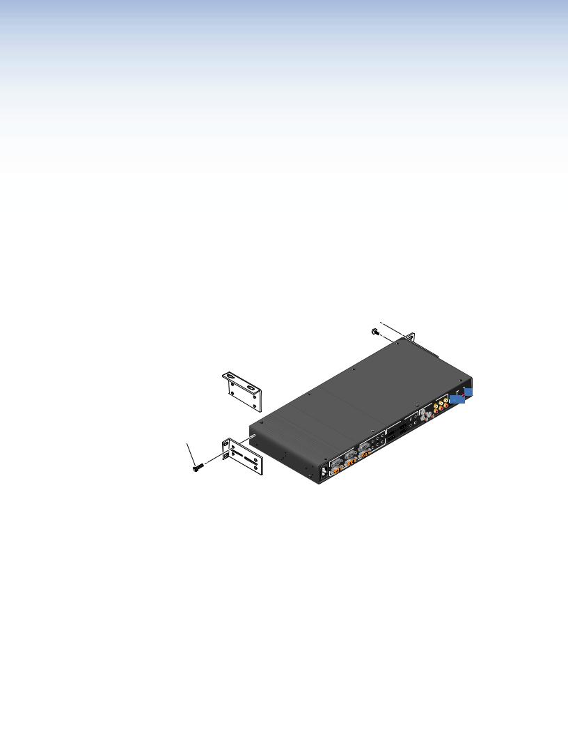
Mounting the Switcher
The MPS 409 is housed in 1U, full rack width metal enclosure rackor desk-mountable. The MBD 149 1U through-desk and rack mounting kit (#70-077-03) is included with the
switchers. The switchers may also be surface mounted under a table, desk, or podium, or on a wall, using the optional MBU 149 1U under-desk mounting kit (#70-222-01).
Mounting Screws (2 Plcs) 
Each Side 
Optional Furniture Mounting Bracket
-or-
#8 Screw (4 Plcs)
Each Side
Supplied Rack Mounting Bracket
1
 .2A
.2A
-240V 100
Hz 50/60
VIDEO1
|
|
L |
|
1 |
|
|
OUTPUT |
R |
|
3 |
|
|
1 |
|
HDMI |
2 |
|
3 |
OUTPUT |
|
|
|
|
|
2 |
|
|
1 |
OUTPUT |
|
OUTPUT |
|
2 |
2 |
|
|
1 |
OUTPUT |
OUTPUT |
VGA/YUV |
2 |
|
1 |
2 |
|
D |
|
MIC/LINE |
LINE |
ON |
|
OUTPUT |
OFF MIC |
2 |
L |
|
L
R
R
-232 RS
Figure 2. Mounting the MPS switcher
UL Rack Mounting Guidelines
The following Underwriters Laboratories (UL) guidelines pertain to the safe installation of the MPS 409 in a rack.
1.Elevated operating ambient temperature — If installed in a closed or multi-unit rack assembly, the operating ambient temperature of the rack environment may be greater than room ambient temperature. Therefore, install the device in an environment compatible with the maximum ambient temperature (Tma = +122 °F, +50 °C) specified by Extron.
2.Reduced air flow — Install the equipment in a rack so that the amount of air flow required for safe operation of the equipment is not compromised.
MPS 409 • Installation |
4 |
3.Mechanical loading — Mount the equipment in the rack so that a hazardous condition is not achieved due to uneven mechanical loading.
4.Circuit overloading — Connect the equipment to the supply circuit and consider the effect that circuit overloading might have on overcurrent protection and supply wiring. Appropriate consideration of equipment nameplate ratings should be used when addressing this concern.
5.Reliable earthing (grounding) — Maintain reliable grounding of rack-mounted equipment. Pay particular attention to supply connections other than direct connections to the branch circuit (e.g. use of power strips).
MPS 409 • Installation |
5 |
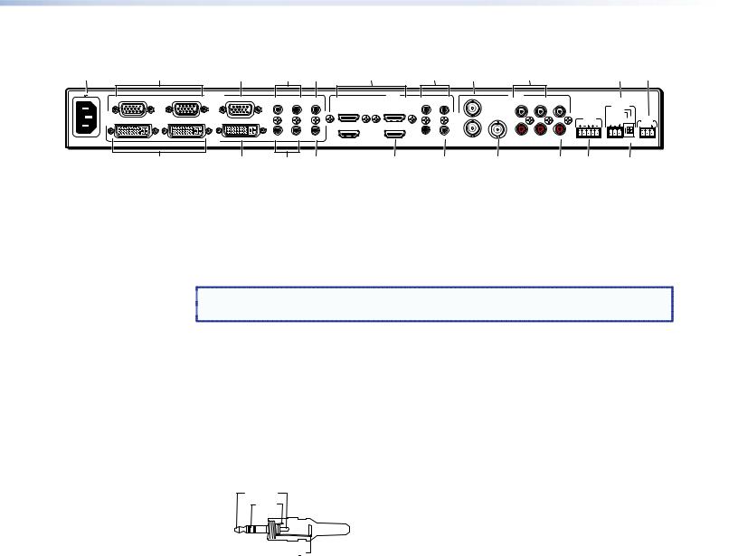
Rear Panel Connections
a |
b |
|
|
c |
|
d e |
f |
g h |
|
|
i |
|
|
j k |
|||||
100-240V 0.4A MAX |
1 |
2 |
VGA/YUV |
OUTPUT |
|
|
|
HDMI |
|
1 |
|
VIDEO |
|
|
|
|
|
|
|
|
|
1 |
2 |
OUTPUT |
1 |
3 |
|
|
1 |
2 |
OUTPUT |
|
|
|
|
|
|||
|
|
|
|
|
|
|
|
MIC/LINE |
|
|
|||||||||
|
|
|
|
|
|
|
|
|
|
|
|
L |
|
|
|
|
|
||
|
|
|
|
|
|
|
1 |
3 |
|
|
|
L |
L |
|
LEVEL |
|
|
|
|
|
|
|
|
|
|
|
|
|
|
|
+48V |
|
|
|
|||||
|
|
|
|
|
|
|
|
|
|
|
OUTPUT |
|
|
|
PROGRAM |
|
|
LINE |
|
|
1 |
2 |
|
OUTPUT |
|
|
|
|
|
|
|
|
|
AUDIO |
MIC/LINE |
ON |
RS-232 |
||
|
|
|
|
|
OUTPUT |
|
|
|
R |
|
R |
L OUT R |
IN |
ON |
|
Tx Rx |
|||
|
|
|
|
|
|
|
2 |
|
|
|
R |
|
|
|
|||||
|
|
|
|
|
|
|
|
|
|
|
|
|
|
|
|||||
|
|
|
|
|
1 |
2 |
OUTPUT |
2 |
OUTPUT |
|
|
|
|
|
|
|
1 |
2 |
|
50/60 Hz |
|
|
DVI-D |
|
2 |
|
|
|
|
|
|
OFF |
MIC |
|
|||||
|
|
|
|
|
|
|
|
|
|
|
|
|
|
|
|||||
|
l |
|
|
m |
|
n |
o |
p |
q |
|
r |
|
|
s |
t |
|
u |
|
|
Figure 3. MPS 409 rear panel
a b
AC power — Connect to standard AC power: 100-240 VAC, at 50-60 Hz
VGA video input group — Two female 15-pin HD connectors for VGA input (numbered 1 and 2). The connectors accept VGA or YUV signals. For YUV signals, red color channels are used for R-Y (Pr), blue color channels are used for B-Y (Pb), and green color channels are used for Y.
 NOTE: The MPS 409 does not scale or convert video. The input signal format will also
  be the output format.
cVGA video output — One 15-pin HD connector with the selected VGA/YUV video output.
dVGA audio inputs — Two 3.5 mm stereo audio connectors corresponding to the VGA video inputs. Each audio input can be adjusted from -18 dB to +24 dB.
Connecting the 3.5 mm mini-plugs
1.Use pre-made Extron 3.5 mm stereo audio cables (see www.extron.com), or
cut bulk audio cable and solder a 3.5 mm mini-plug to the cable as shown.
Tip (L+)
Ring
(R+)
 Sleeve (
 )
)
3.5 mm Stereo Plug Connector
(unbalanced)
Figure 4. 3.5 mm, mini-plug audio connector
2. Plug the connector into the MPS 409.
eVGA audio output — One 3.5 mm stereo audio output connector with audio output from the selected VGA input. Connect to the audio input of an audio amplifier. See figure 4 above for wiring.
fHDMI video input group — Three HDMI connectors for HDMI compliant video input (numbered 1 through 3). Connect to any HDMI source device using standard HDMI cable.
g h i
HDMI audio inputs — Three 3.5 mm stereo audio connectors corresponding to the HDMI video input sources. See Figure 4 above for wiring.
Composite video input group — Two BNC connectors for composite video (numbered 1 and 2) from any composite video source device.
Composite audio inputs — Four RCA connectors for two stereo audio inputs corresponding to the two composite video sources.
MPS 409 • Installation |
6 |
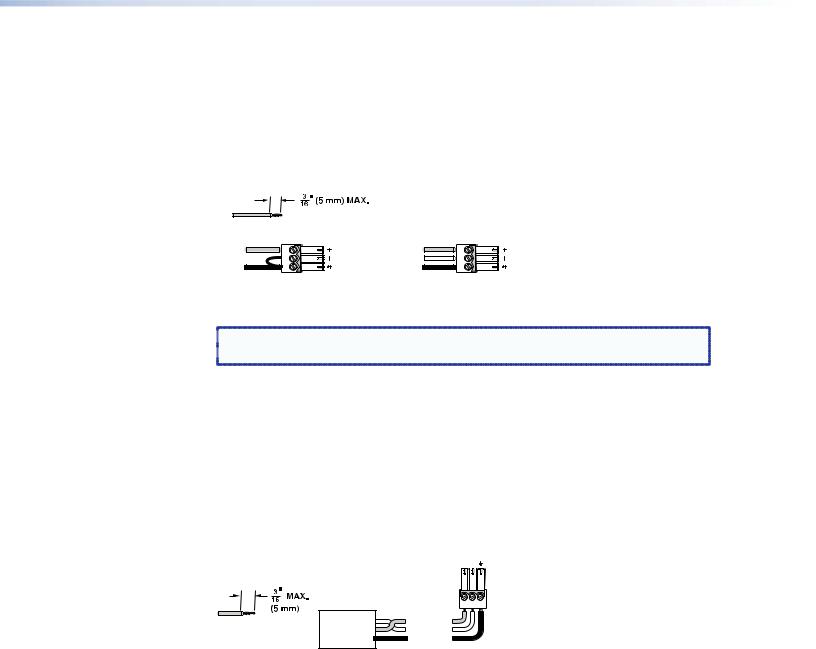
jMic/Line input — One 3-pole captive screw connector switchable between mic and line level inputs. A two position DIP switch (u) selects mic or line input level.
Connecting the 3-pole captive screw microphone connector
1.Use a pre-made 3-pole captive screw microphone cable, or
cut bulk microphone cable, and attach the 3-pole captive screw connector to the cable.
Do not tin the wires!
Tip |
Tip |
|
Ring |
Sleeve |
Sleeve |
Unbalanced Mic Input Balanced Mic Input
Figure 5. 3.5 mm, 3-pole captive screw microphone connector
 NOTE: Do not tin the mic wire leads before installing into the connector. Tinned
  wires are not as secure in the connector and could be pulled out.
2. Plug the 3-pole captive screw connector into the MPS 409.
kRS-232 remote — One female 9-pin D connector for a host computer or a controller using Simple Instruction Set (SIS) or Windows-based control software.
Connecting the 3-pole captive screw RS-232 connector
For RS-232 control, use a control cable with only pins 2, 3, and 5 connected. See SIS Programming and Control on page 20 for SIS commands definitions and details on how to install and use the control software.
The RS-232 input uses a 3-pole captive screw connector wired as shown:
Tx Rx
|
RS-232 |
|
|
|
Device |
Bidirectional |
|
|
|
||
Do not tin |
Transmit (Tx) |
Transmit (Tx) |
|
the wires! |
Receive (Rx) |
Receive (Rx) |
|
Ground ( _ ) |
Ground ( _ ) |
||
|
Figure 6. RS-232 Captive screw connector wiring
See Remote Control Port (RS-232) on page 20 for additional wiring details.
lDVI-D video input group — Two female DVI connectors for DVI-D signals only (numbered 1 and 2). Connect DVI-D sources to either or both connectors.
m DVI-D video output — Connect a DVI-D display device to this connector.
nDVI audio inputs — Two 3.5 mm stereo audio connectors corresponding to the DVI video inputs. Connect to the audio output of the corresponding DVI-D video input. See figure 4 for wiring.
oDVI audio output — 3.5 mm stereo audio output connector with audio output from the selected DVI input. Connect to the audio input of an audio amplifier. See figure 4 for wiring.
pHDMI video output — Connect an HDMI display device for output from the selected HDMI input.
MPS 409 • Installation |
7 |
Loading...