


 Loading...
MVX Plus 128 VGA A
Computer video (VGA) and Audio Matrix Switcher
68-521-30 Rev. B
04 07
Precautions
Safety Instructions • English
This symbol is intended to alert the user of important operating and maintenance (servicing) instructions in the literature provided with the equipment.
This symbol is intended to alert the user of the presence of uninsulated dangerous voltage within the product’s enclosure that may present a risk of electric shock.
Caution
Read Instructions • Read and understand all safety and operating instructions before using the equipment.
Retain Instructions • The safety instructions should be kept for future reference.
Follow Warnings • Follow all warnings and instructions marked on the equipment or in the user information.
Avoid Attachments • Do not use tools or attachments that are not recommended by the equipment manufacturer because they may be hazardous.
Consignes de Sécurité • Français
Ce symbole sert à avertir l’utilisateur que la documentation fournie avec le matériel contient des instructions importantes concernant l’exploitation et la maintenance (réparation).
Ce symbole sert à avertir l’utilisateur de la présence dans le boîtier de l’appareil de tensions dangereuses non isolées posant des risques d’électrocution.
Attention
Lire les instructions• Prendre connaissance de toutes les consignes de sécurité et d’exploitation avant d’utiliser le matériel.
Conserver les instructions• Ranger les consignes de sécurité afin de pouvoir les consulter à l’avenir.
Respecter les avertissements • Observer tous les avertissements et consignes marqués sur le matériel ou présentés dans la documentation utilisateur.
Eviter les pièces de fixation • Ne pas utiliser de pièces de fixation ni d’outils non recommandés par le fabricant du matériel car cela risquerait de poser certains dangers.
Sicherheitsanleitungen • Deutsch
Dieses Symbol soll dem Benutzer in der im Lieferumfang enthaltenen Dokumentation besonders wichtige Hinweise zur Bedienung und Wartung (Instandhaltung) geben.
Dieses Symbol soll den Benutzer darauf aufmerksam machen, daß im Inneren des Gehäuses dieses Produktes gefährliche Spannungen, die nicht isoliert sind und die einen elektrischen Schock verursachen können, herrschen.
Achtung
Lesen der Anleitungen • Bevor Sie das Gerät zum ersten Mal verwenden, sollten Sie alle Sicherheits-und Bedienungsanleitungen genau durchlesen und verstehen.
Aufbewahren der Anleitungen • Die Hinweise zur elektrischen Sicherheit des Produktes sollten Sie aufbewahren, damit Sie im Bedarfsfall darauf zurückgreifen können.
Befolgen der Warnhinweise • Befolgen Sie alle Warnhinweise und Anleitungen auf dem Gerät oder in der Benutzerdokumentation.
Keine Zusatzgeräte • Verwenden Sie keine Werkzeuge oder Zusatzgeräte, die nicht ausdrücklich vom Hersteller empfohlen wurden, da diese eine Gefahrenquelle darstellen können.
Instrucciones de seguridad • Español
Este símbolo se utiliza para advertir al usuario sobre instrucciones importantes de operación y mantenimiento (o cambio de partes) que se desean destacar en el contenido de la documentación suministrada con los equipos.
Este símbolo se utiliza para advertir al usuario sobre la presencia de elementos con voltaje peligroso sin protección aislante, que puedan encontrarse dentro de la caja o alojamiento del producto, y que puedan representar riesgo de electrocución.
Precaucion
Leer las instrucciones • Leer y analizar todas las instrucciones de operación y seguridad, antes de usar el equipo.
Conservar las instrucciones • Conservar las instrucciones de seguridad para futura consulta.
Obedecer las advertencias • Todas las advertencias e instrucciones marcadas en el equipo o en la documentación del usuario, deben ser obedecidas.
Evitar el uso de accesorios • No usar herramientas o accesorios que no sean especificamente recomendados por el fabricante, ya que podrian implicar riesgos.
•
••
••
Warning
Power sources • This equipment should be operated only from the power source indicated on the product. This equipment is intended to be used with a main power system with a grounded (neutral) conductor. The third (grounding) pin is a safety feature, do not attempt to bypass or disable it.
Power disconnection • To remove power from the equipment safely, remove all power cords from the rear of the equipment, or the desktop power module (if detachable), or from the power source receptacle (wall plug).
Power cord protection • Power cords should be routed so that they are not likely to be stepped on or pinched by items placed upon or against them.
Servicing • Refer all servicing to qualified service personnel. There are no user-serviceable parts inside. To prevent the risk of shock, do not attempt to service this equipment yourself because opening or removing covers may expose you to dangerous voltage or other hazards.
Slots and openings • If the equipment has slots or holes in the enclosure, these are provided to prevent overheating of sensitive components inside. These openings must never be blocked by other objects.
Lithium battery • There is a danger of explosion if battery is incorrectly replaced. Replace it only with the same or equivalent type recommended by the manufacturer. Dispose of used batteries according to the manufacturer’s instructions.
Avertissement
Alimentations• Ne faire fonctionner ce matériel qu’avec la source d’alimentation indiquée sur l’appareil. Ce matériel doit être utilisé avec une alimentation principale comportant un fil de terre (neutre). Le troisième contact (de mise à la terre) constitue un dispositif de sécurité : n’essayez pas de la contourner ni de la désactiver.
Déconnexion de l’alimentation• Pour mettre le matériel hors tension sans danger, déconnectez tous les cordons d’alimentation de l’arrière de l’appareil ou du module d’alimentation de bureau (s’il est amovible) ou encore de la prise secteur.
Protection du cordon d’alimentation • Acheminer les cordons d’alimentation de manière à ce que personne ne risque de marcher dessus et à ce qu’ils ne soient pas écrasés ou pincés par des objets.
Réparation-maintenance • Faire exécuter toutes les interventions de réparation-maintenance par un technicien qualifié. Aucun des éléments internes ne peut être réparé par l’utilisateur. Afin d’éviter tout danger d’électrocution, l’utilisateur ne doit pas essayer de procéder lui-même à ces opérations car l’ouverture ou le retrait des couvercles risquent de l’exposer à de hautes tensions et autres dangers.
Fentes et orifices • Si le boîtier de l’appareil comporte des fentes ou des orifices, ceux-ci servent à empêcher les composants internes sensibles de surchauffer. Ces ouvertures ne doivent jamais être bloquées par des objets.
Lithium Batterie • Il a danger d’explosion s’ll y a remplacment incorrect de la batterie. Remplacer uniquement avec une batterie du meme type ou d’un ype equivalent recommande par le constructeur. Mettre au reut les batteries usagees conformement aux instructions du fabricant.
Vorsicht
Stromquellen • Dieses Gerät sollte nur über die auf dem Produkt angegebene Stromquelle betrieben werden. Dieses Gerät wurde für eine Verwendung mit einer Hauptstromleitung mit einem geerdeten (neutralen) Leiter konzipiert. Der dritte Kontakt ist für einen Erdanschluß, und stellt eine Sicherheitsfunktion dar. Diese sollte nicht umgangen oder außer Betrieb gesetzt werden.
Stromunterbrechung • Um das Gerät auf sichere Weise vom Netz zu trennen, sollten Sie alle Netzkabel aus der Rückseite des Gerätes, aus der externen Stomversorgung (falls dies möglich ist) oder aus der Wandsteckdose ziehen.
Schutz des Netzkabels • Netzkabel sollten stets so verlegt werden, daß sie nicht im Weg liegen und niemand darauf treten kann oder Objekte daraufoder unmittelbar dagegengestellt werden können.
Wartung • Alle Wartungsmaßnahmen sollten nur von qualifiziertem Servicepersonal durchgeführt werden. Die internen Komponenten des Gerätes sind wartungsfrei. Zur Vermeidung eines elektrischen Schocks versuchen Sie in keinem Fall, dieses Gerät selbst öffnen, da beim Entfernen der Abdeckungen die Gefahr eines elektrischen Schlags und/oder andere Gefahren bestehen.
Schlitze und Öffnungen • Wenn das Gerät Schlitze oder Löcher im Gehäuse aufweist, dienen diese zur Vermeidung einer Überhitzung der empfindlichen Teile im Inneren. Diese Öffnungen dürfen niemals von anderen Objekten blockiert werden.
Litium-Batterie • Explosionsgefahr, falls die Batterie nicht richtig ersetzt wird. Ersetzen Sie verbrauchte Batterien nur durch den gleichen oder einen vergleichbaren Batterietyp, der auch vom Hersteller empfohlen wird. Entsorgen Sie verbrauchte Batterien bitte gemäß den Herstelleranweisungen.
Advertencia
Alimentación eléctrica • Este equipo debe conectarse únicamente a la fuente/tipo de alimentación eléctrica indicada en el mismo. La alimentación eléctrica de este equipo debe provenir de un sistema de distribución general con conductor neutro a tierra. La tercera pata (puesta a tierra) es una medida de seguridad, no puentearia ni eliminaria.
Desconexión de alimentación eléctrica • Para desconectar con seguridad la acometida de alimentación eléctrica al equipo, desenchufar todos los cables de alimentación en el panel trasero del equipo, o desenchufar el módulo de alimentación (si fuera independiente), o desenchufar el cable del receptáculo de la pared.
Protección del cables de alimentación • Los cables de alimentación eléctrica se deben instalar en lugares donde no sean pisados ni apretados por objetos que se puedan apoyar sobre ellos.
Reparaciones/mantenimiento • Solicitar siempre los servicios técnicos de personal calificado. En el interior no hay partes a las que el usuario deba acceder. Para evitar riesgo de electrocución, no intentar personalmente la reparación/mantenimiento de este equipo, ya que al abrir o extraer las tapas puede quedar expuesto a voltajes peligrosos u otros riesgos.
Ranuras y aberturas • Si el equipo posee ranuras o orificios en su caja/alojamiento, es para evitar el sobrecalientamiento de componentes internos sensibles. Estas aberturas nunca se deben obstruir con otros objetos.
Batería de litio • Existe riesgo de explosión si esta batería se coloca en la posición incorrecta. Cambiar esta batería únicamente con el mismo tipo (o su equivalente) recomendado por el fabricante. Desachar las baterías usadas siguiendo las instrucciones del fabricante.
• |
|
|
|
|
|
• |
|
|
• |
|
|
• |
|
|
• |
|
|
• |
|
|

FCC Class A Notice
NThis equipment has been tested and found to comply with the limits for a ClassAdigital device, pursuant to part 15 of the FCC Rules. These limits are designedtoprovidereasonableprotectionagainstharmfulinterferencewhen the equipment is operated in a commercial environment. This equipment generates, uses and can radiate radio frequency energy and, if not installed and used in accordance with the instruction manual, may cause harmful interference to radio communications. Operation of this equipment in a residential area is likely to cause harmful interference, in which case the user will be required to correct the interference at his own expense.
NThisunitwastestedwithshieldedcablesontheperipheraldevices. Shielded cables must be used with the unit to ensure compliance.
This device complies with Part 15 of the FCC Rules. Operation is subject to the following two conditions: (1) this device may not cause harmful interference, and (2) this device must accept any interference received, including interference that may cause undesired operation
Quick Start — MVX Plus 128 VGA A Matrix Switcher
Installation
Step 1
Turn off power to the input and output devices, and disconnect the power cords.
Step 2 — Inputs
a. Connect up to 12 high resolution video inputs to the 15-pin HD input connectors.
b. Connect up to 12 stereo or mono audio inputs to the 5-pin captive screw connectors.
Tip |
Tip |
L |
|
Sleeve |
Ring |
||
|
|||
|
Sleeve (s) |
|
|
Tip |
Tip |
R |
|
Sleeve |
Ring |
||
|
Unbalanced Input |
Balanced Input |
(high impedance) |
(high impedance) |
Step 3 — Outputs
a. Connect up to 8 high resolution video devices to the 15-pin HD output connectors.
b. Connect up to 8 balanced or unbalanced stereo audio or mono audio devices to the 5-pin captive screw connectors.
Tip |
Tip |
L |
|
NO GROUND HERE. |
Ring |
||
|
|||
Sleeve(s) |
Sleeve(s) |
|
|
Tip |
Tip |
R |
|
NO GROUND HERE. |
Ring |
||
|
Unbalanced Output |
Balanced Output |
CAUTION Connect the sleeve to ground. Connecting the sleeve to a negative (-) terminal will damage the audio output circuits.
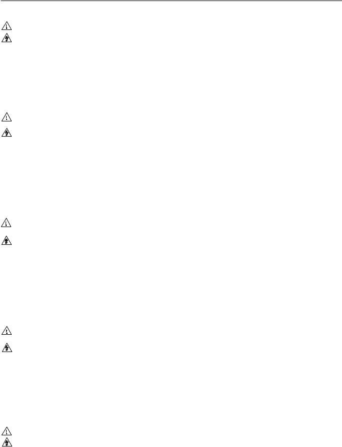
Step 4 — RS-232/RS-422
If desired, connect a control system or computer to the Remote RS-232/RS-422 port.
|
|
Pin RS-232 Function |
RS-422 Function |
|||
|
|
1 |
— |
Not used |
— |
Not used |
|
|
2 |
TX |
Transmit |
TX– |
Transmit (–) |
1 |
6 |
3 |
RX |
Receive |
RX– |
Receive (–) |
|
|
4 |
— |
Not used |
— |
Not used |
5 |
9 |
5 |
Gnd |
Ground |
Gnd |
Ground |
6 |
— |
Not used |
— |
Not used |
||
|
|
7 |
— |
Not used |
RX+ |
Receive (+) |
|
|
8 |
— |
Not used |
TX+ |
Transmit (+) |
|
|
9 |
— |
Not used |
— |
Not used |
Step 5
If desired, connect a control system or computer to the front panel Configuration (RS-232) port. Use an optional 9-pin D to 2.5 mm mini jack TRS RS-232 cable, part #70-335-01.
Step 6 — Ethernet
If desired, connect a network WAN or LAN hub, a control system, or computer to the Ethernet RJ-45 port. See chapter 2, “Installation”, for details.
•Network connection — Wire as a patch (straight) cable.
•Computer or control system connection —
Wire the interface cable as a crossover cable.
Step 7 — Power
Plug the switcher into a grounded AC source.
Definitions
Tie — An input-to-output connection
Set of ties — An input tied to 2 or more outputs
Configuration — One or more ties or sets of ties
Current configuration — The currently active configuration (also called configuration 0)
Global preset — A configuration that has been stored. One global preset can be assigned to each input button. When a global preset is retrieved from memory, it becomes the current configuration.
Front Panel Controls
Input and output buttons select inputs and outputs. Output buttons light amber to indicate video and audio ties. The buttons light green to indicate video-only ties. The buttons light red to indicate audio-only ties. Input and output buttons also select presets.
The output buttons also display the selected input’s audio level.
The input buttons also display the selected output’s volume level.
Enter button saves changes.
Preset button saves a configuration as a preset or recalls a previously-defined preset.
View button selects a view-only mode that prevents inadvertent configuration changes. On audio models, View decrements the level and volume. See “Viewing and adjusting the audio level” on page QS-2.
PRELIMINARY
MVX Plus 128 VGA A Matrix Switcher • Quick Start QS-1
PRELIMINARY
Quick Start —
MVX Plus 128 VGA A Matrix Switcher, continued
Esc button cancels selections in progress and resets the front panel button indications. The Esc button does not reset the current configuration, the RGBHV and audio selection, any presets, or any audio level or volume settings. On audio models, Esc increments the level and volume. See
“Viewing and adjusting the audio level” in the next column.
RGBHV and Audio buttons select/deselect video and/or audio. The Audio button blinks to indicate audio breakaway. The Audio button also selects the audio level/adjust mode. See “Viewing and adjusting the audio level” in the next column.
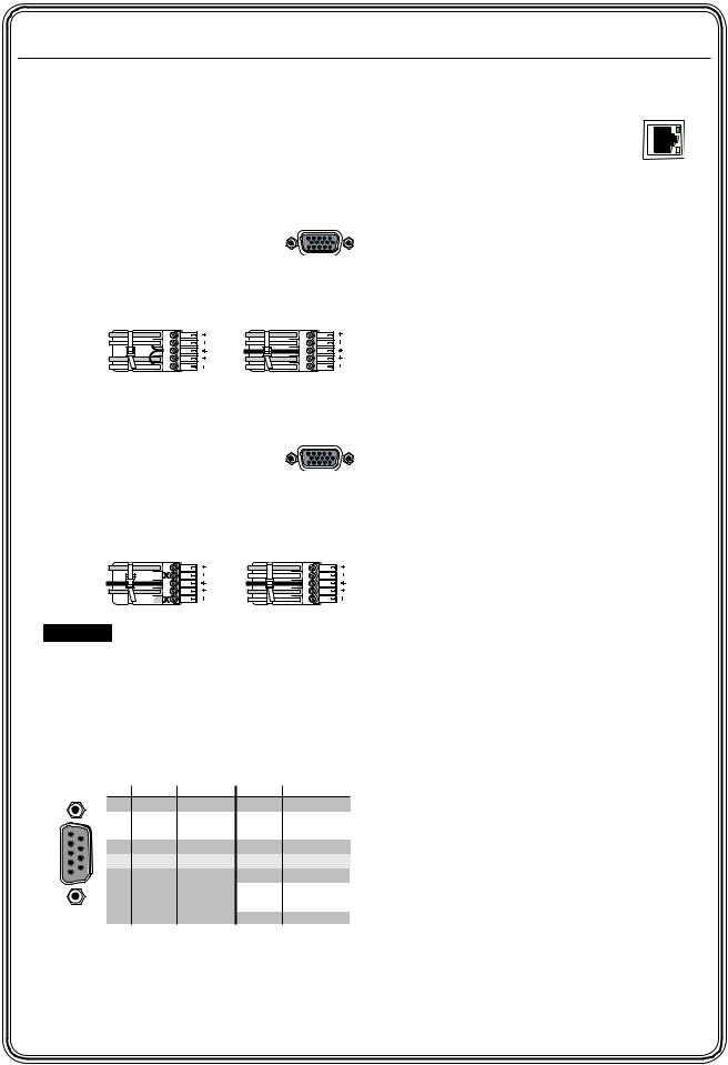
Creating a tie
1. Press and release the RGBHV and/or Audio I/O button(s) to select or deselect video and/ or audio as desired.
I / O
RGBHV AUDIO
Green when selected. Red when selected.
Off when deselected. Off when deselected.
2. Press and release the desired input button.
The button lights to indicate the selection.
 5
5 
3. Press and release the desired output button(s).
Amber indicates RGBHV/video and audio tie.
Green indicates RGBHV/video only tie.
Red indicates audio only tie.
3 |
4 |
8 |
ENTER |
|
Green indicates the need to confirm the change.
4. Press and release the Enter button.
Saving or recalling a preset
1. Save a preset — Press and hold the Preset button for 2 seconds.
Recall a preset — Press and release the Preset button.
Save a |
PRESET 2 seconds |
PRESET |
preset |
||
|
Press and hold. |
Preset button blinks. |
Recall a |
PRESET |
PRESET |
preset |
||
|
Press and release. |
Preset button lights. |
All input and output buttons with assigned presets light red.
The configuration data at assigned preset locations will be overwritten.
|
|
|
|
|
INPUTS |
1 |
2 |
3 |
4 |
5 |
6 |
2. Press and release the desired input or output button.
The button blinks red to indicate that this preset is selected to save or recall.
1 |
ENTER |
The Enter button blinks |
|
green to indicate the need |
|||
|
|||
|
|
to activate the save or recall. |
3. Press and release the Enter button.
Viewing and adjusting the audio level
1. Press and hold the Audio button.
AUDIO |
2 seconds |
AUDIO |
|
|
|
||
Press and |
Audio button blinks. |
||
hold |
|
|
|
2. Press an input or output button. See chapter 3, “Operation” to read the displayed value.
5 |
Press an Input button to adjust gain/attenuation. |
|
|
Press an Output button to adjust volume. |
|
1 |
2 |
Output buttons display gain/attenuation. |
Input buttons display volume. |
||
3. Increase and decrease the gain/attenuation or volume level by pressing the Esc (>) and View (<) buttons.
4. Press and release the Audio button to exit.
 button decreases
  button increases the level or volume. the level or volume.
VIEW ESC
QS-2 MVX Plus 128 VGA A Matrix Switcher • Quick Start

Table of Contents
Chapter One • Introduction ....................................................................................................... |
1-1 |
About this Manual...................................................................................................................... |
1-2 |
About the MVX Plus 128 VGA A Matrix Switcher................................................... |
1-2 |
Definitions....................................................................................................................................... |
1-3 |
Features............................................................................................................................................. |
1-4 |
Chapter Two • Installation........................................................................................................... |
2-1 |
Mounting the Switcher........................................................................................................... |
2-2 |
UL requirements ................................................................................................................... |
2-2 |
Mounting ins tructions .......................................................................................................... |
2-2 |
Rear Panel Cabling and Views............................................................................................ |
2-3 |
Video connections ...................................................................................................................... |
2-3 |
Audio connections ..................................................................................................................... |
2-4 |
RS-232/RS-422 connection......................................................................................................... |
2-5 |
Ethernet connection.................................................................................................................. |
2-6 |
Cabling.and.RJ-45 connector wiring................................................................................... |
2-6 |
Res et button............................................................................................................................... |
2-7 |
Power connection..................................................................................................................... |
2-7 |
Front Panel Configuration Port.......................................................................................... |
2-8 |
Chapter Three • Operation ......................................................................................................... |
3-1 |
Front Panel Controls and Indicators................................................................................ |
3-2 |
Definitions ................................................................................................................................... |
3-2 |
Input and output.buttons ......................................................................................................... |
3-3 |
Control buttons .......................................................................................................................... |
3-4 |
I/O controls .................................................................................................................................. |
3-7 |
Button icons ................................................................................................................................ |
3-8 |
Front Panel Operations............................................................................................................ |
3-8 |
Front panel s ecurity lockouts ................................................................................................... |
3-8 |
Power........................................................................................................................................... |
3-8 |
Creating a configuration.......................................................................................................... |
3-9 |
Example 1:.Creating a s et.of.video.and audio ties ........................................................... |
3-10 |
Example 2: Adding a tie to a s et of video and audio ties ................................................ |
3-12 |
Example 3: Removing a tie from a s et of video and audio ties ....................................... |
3-14 |
Viewing a configuration......................................................................................................... |
3-16 |
Example 4: Viewing video and audio,.audio.only,.and video only ties ........................... |
3-17 |
I/O grouping............................................................................................................................. |
3-19 |
Example 5: Grouping inputs .and outputs ......................................................................... |
3-21 |
Setting RGB delay.................................................................................................................... |
3-23 |
Example 6: Setting the RGB delay for.an.output............................................................. |
3-24 |
Us ing pres ets ............................................................................................................................. |
3-26 |
Example 7: Saving a pres et................................................................................................ |
3-27 |
Example.8:.Recalling a pres et............................................................................................ |
3-28 |
Muting and unmuting video and/or audio outputs ........................................................... |
3-29 |
Example 9: Muting.and.unmuting.an.output.................................................................. |
3-29 |
PRELIMINARY
MVX Plus 128 VGA A Matrix Switcher • Table of Contents

PRELIMINARY
Table of Contents, cont’d
Viewing and adjus ting the input audio level...................................................................... |
3-32 |
Example.10:.Viewing.and.adjus ting.an.input.audio.level............................................... |
3-34 |
Viewing and adjus ting the output volume.......................................................................... |
3-36 |
Reading.the.dis played.volume.......................................................................................... |
3-37 |
Example.11:.Viewing.and.adjus ting.an.output.volume.level.......................................... |
3-39 |
Setting the front panel locks (Executive modes ) ................................................................. |
3-41 |
Selecting.Lock.mode.2.or.toggling.between.mode.2.and.mode.0................................. |
3-41 |
Selecting.Lock.mode.2.or.toggling.between.mode.2.and.mode.1................................. |
3-42 |
Performing a s ys tem res et from the front panel................................................................ |
3-42 |
Background illumination........................................................................................................ |
3-43 |
Selecting the rear panel Remote port protocol and baud rate........................................ |
3-43 |
Rear Panel Operations............................................................................................................ |
3-44 |
Performing s oft s ys tem res ets ................................................................................................ |
3-45 |
Performing a hard res et.......................................................................................................... |
3-46 |
Optimizing the Audio............................................................................................................. |
3-47 |
Troubleshooting......................................................................................................................... |
3-47 |
Configuration Worksheets.................................................................................................. |
3-48 |
Works heet example 1: Sys tem equipment........................................................................... |
3-48 |
Works heet example 2: Daily configuration......................................................................... |
3-49 |
Works heet example 3: Tes t configuration........................................................................... |
3-50 |
Configuration works heet........................................................................................................ |
3-51 |
Chapter Four • Programmer’s Guide................................................................................... |
4-1 |
Serial Ports...................................................................................................................................... |
4-2 |
Rear panel Remote port............................................................................................................ |
4-2 |
Front panel Configuration port............................................................................................... |
4-3 |
Ethernet Link................................................................................................................................. |
4-4 |
Ethernet connection.................................................................................................................. |
4-4 |
Default IP addresss es ................................................................................................................... |
4-4 |
Host-to-Switcher Instructions.............................................................................................. |
4-5 |
Switcher-Initiated Messages................................................................................................ |
4-5 |
Switcher Error Responses...................................................................................................... |
4-6 |
Using the Command/Response Tables............................................................................ |
4-6 |
Command/Response Table for SIS™ Commands....................................................... |
4-7 |
Symbol definitions ..................................................................................................................... |
4-7 |
Command/res pons e table for SIS commands ......................................................................... |
4-8 |
Command/Response Table for IP SIS Commands.................................................. |
4-17 |
Symbol definitions ................................................................................................................... |
4-17 |
Command/res pons e table for IP SIS commands ................................................................... |
4-18 |
Special Characters.................................................................................................................... |
4-19 |
ii MVX Plus 128 VGA A Matrix Switcher • Table of Contents

Chapter Five • Matrix Software.............................................................................................. |
5-1 |
Matrix Switchers Control Program.................................................................................. |
5-2 |
Ins talling the s oftware.............................................................................................................. |
5-2 |
Software operation via Ethernet............................................................................................. |
5-3 |
Ethernet.protocol.s ettings ................................................................................................... |
5-3 |
Us ing the Matrix Switcher Control s oftware......................................................................... |
5-4 |
IP Settings /Options .window..................................................................................................... |
5-6 |
Matrix.IP.Addres s .field......................................................................................................... |
5-7 |
Extron.Name/Des criptor.field.............................................................................................. |
5-8 |
Gateway.IP.addres s .field...................................................................................................... |
5-8 |
Subnet.Mas k.field................................................................................................................. |
5-8 |
Hardware.Addres s .field....................................................................................................... |
5-8 |
Us e.DHCP.checkbox.............................................................................................................. |
5-9 |
Date.field.............................................................................................................................. |
5-9 |
Time (local) .field................................................................................................................... |
5-9 |
Sync Time.to.PC.button........................................................................................................ |
5-9 |
GMT (offs et) .field................................................................................................................. |
5-9 |
Us e Daylight.Savings .checkbox.......................................................................................... |
5-10 |
Adminis trator Pas s word.field............................................................................................ |
5-10 |
Us er Pas s word.field............................................................................................................ |
5-10 |
Mail Server.IP.Addres s .field............................................................................................... |
5-11 |
Mail Server.Domain.Name.field........................................................................................ |
5-11 |
E-mail.Addres s ee.fields ...................................................................................................... |
5-12 |
Updating firmware.................................................................................................................. |
5-13 |
Ethernet-connected.firmware.upload.............................................................................. |
5-14 |
Serial-port-connected.firmware.upload........................................................................... |
5-15 |
Uploading HTML files .............................................................................................................. |
5-17 |
Windows .buttons , drop boxes , and tras hcan...................................................................... |
5-18 |
Windows .menus ....................................................................................................................... |
5-18 |
File menu............................................................................................................................ |
5-18 |
Tools .menu.......................................................................................................................... |
5-19 |
Preferences .menu............................................................................................................... |
5-20 |
Master-Reset s election........................................................................................................ |
5-22 |
Us ing Emulation mode.......................................................................................................... |
5-22 |
Us ing the help s ys tem............................................................................................................. |
5-22 |
Special Characters.................................................................................................................... |
5-22 |
Button-Label Generator Program................................................................................... |
5-23 |
Us ing the Button-Label Generator s oftware....................................................................... |
5-24 |
PRELIMINARY
MVX Plus 128 VGA A Matrix Switcher • Table of Contents |
iii |

PRELIMINARY
Table of Contents, cont’d
Chapter 6 • HTML Operation.................................................................................................... |
5-25 |
Download the Startup Page................................................................................................. |
6-2 |
System Status Page................................................................................................................... |
6-3 |
DSVP page................................................................................................................................... |
6-4 |
System Configuration Page.................................................................................................. |
6-5 |
IP Settings .fields ......................................................................................................................... |
6-6 |
Unit Name field.................................................................................................................... |
6-6 |
DHCP radio buttons .............................................................................................................. |
6-6 |
IP Address .field..................................................................................................................... |
6-6 |
Gateway IP Address .field..................................................................................................... |
6-6 |
Subnet Mas k field................................................................................................................. |
6-6 |
MAC Address .field................................................................................................................ |
6-6 |
Firmware field...................................................................................................................... |
6-6 |
Model field........................................................................................................................... |
6-6 |
Part Number field................................................................................................................. |
6-7 |
Date/Time Settings .fields .......................................................................................................... |
6-7 |
Passs words .page.......................................................................................................................... |
6-8 |
Email Settings .page................................................................................................................... |
6-9 |
Mail IP.Addres s .field............................................................................................................. |
6-9 |
Domain.Name.field.............................................................................................................. |
6-9 |
Email addres s .fields ............................................................................................................ |
6-10 |
Firmware Upgrade page......................................................................................................... |
6-10 |
File Management Page.......................................................................................................... |
6-11 |
Set and View Ties Page.......................................................................................................... |
6-12 |
Creating a tie............................................................................................................................ |
6-13 |
RGB and Audio Settings .page................................................................................................ |
6-13 |
Changing.the.input.gain.and attenuation....................................................................... |
6-14 |
Muting and unmuting one or all outputs ........................................................................ |
6-15 |
Changing the RGB delay.................................................................................................... |
6-16 |
Changing.the.output.volume.level................................................................................... |
6-17 |
Global Pres ets .page................................................................................................................. |
6-19 |
Saving a pres et................................................................................................................... |
6-19 |
Recalling a.pres et............................................................................................................... |
6-19 |
Special Characters.................................................................................................................... |
6-20 |
iv MVX Plus 128 VGA A Matrix Switcher • Table of Contents
Appendix A • Ethernet Connection..................................................................................... |
A-1 |
Ethernet Link................................................................................................................................ |
A-2 |
Ethernet connection................................................................................................................. |
A-2 |
Default addres s ......................................................................................................................... |
A-2 |
Pinging to determine.Extron.IP.addres s ............................................................................ |
A-3 |
Pinging to determine.Web.IP.addres s ................................................................................ |
A-3 |
Connecting as .a Telnet client.................................................................................................. |
A-4 |
Telnet tips ............................................................................................................................. |
A-4 |
Open............................................................................................................................... |
A-4 |
Es cape.character and Es c key........................................................................................ |
A-5 |
Local echo....................................................................................................................... |
A-5 |
Set.carriage.return-line feed......................................................................................... |
A-5 |
Close ............................................................................................................................... |
A-5 |
Help................................................................................................................................ |
A-5 |
Quit................................................................................................................................. |
A-5 |
Subnetting — A Primer........................................................................................................... |
A-6 |
Gateways .................................................................................................................................... |
A-6 |
Local and remote devices ......................................................................................................... |
A-6 |
IP addresss es .and octets ............................................................................................................. |
A-6 |
Subnet mas ks .and octets .......................................................................................................... |
A-6 |
Determining whether devices .are on.the.s ame s ubnet...................................................... |
A-7 |
Appendix B • Specifications, Part Numbers, Accessories................................... |
B-1 |
Specifications................................................................................................................................ |
B-2 |
Part Numbers and Accessories............................................................................................ |
B-5 |
Included parts ............................................................................................................................. |
B-5 |
Accesss ories .................................................................................................................................. |
B-5 |
Cables ........................................................................................................................................... |
B-6 |
Button Labels................................................................................................................................. |
B-7 |
Ins talling labels .in.the matrix s witcher’s .buttons .................................................................. |
B-7 |
Button label blanks .................................................................................................................... |
B-9 |
MVX Plus 128 VGA A Matrix Switcher • Table of Contents
PRELIMINARY

Table of Contents, cont’d
PRELIMINARY
68-521-30 B
04 07
All trademarks mentioned in this manual are the properties of their respective owners.
vi MVX Plus 128 VGA A Matrix Switcher • Table of Contents


 MVX Plus 128 VGA A Matrix Switcher
Chapter1One
Introduction
PRELIMINARY
About this .Manual
About the MVX Plus .128 VGA A Matrix Switcher
Definitions
Features

PRELIMINARY
Introduction
About this Manual
This manual contains installation, configuration, and operating information for the Extron MVX Plus 128 VGA A 12-input by 8-output wideband computer video (VGA) and audio (A) matrix switcher.
About the MVX Plus 128 VGA A Matrix Switcher
The MVX matrix switcher distributes any of 12 inputs to any combination of
8 outputs. The matrix switcher can route multiple input/output configurations simultaneously.
The matrix switcher is a single box solution to complex wideband video and/or audio routing applications (figure 1-1). Each input and output is individually isolated and buffered, and any input(s) can be switched to any one or all outputs with virtually no crosstalk or signal noise between channels.
Extron
VSC 500
Video Scan Converter
Audio In
Laptop
|
Extron |
|
MVX Series |
|
VGA & Audio |
Extron |
Matrix Switcher |
DVS 304 |
|
Digital Video Scaler |
|
3 |
1 |
4 |
2 |
2
1 |
11 |
|
|
|
9 |
12 |
|
INP |
UTS |
|
12 |
|
|
7 |
10 |
11 |
|
|
|
|
10 |
5 |
|
8 |
|
9 |
|
|
8 |
6 |
INP |
UTS |
7 |
||
|
6 |
|
|
5 |
|
4 |
|
|
3 |
|
|
OU |
TP |
UTS |
|
||
|
|
5 |
3 |
6 |
1 |
4 |
|
|
UTP |
UTS |
2 |
O |
5 |
|
|
|
||
|
4 |
|
|
|
3 |
|
|
|
2 |
|
|
1 |
Audio Out
Audio In 
7 |
8 |
7 6
REMOTE |
RS232/RS422 |
8 |
LAN |
LCD |
|
Projector |
||
|
||
Ethernet |
|
Control System
Sound System
Figure 1-1 — Typical MVX Plus 128 VGA A matrix switcher application
1-2 MVX Plus 128 VGA A Matrix Switcher • Introduction

The MVX Plus 128 VGA A switcher inputs and outputs VGA video on 15-pin HD connectors and audio on 3.5 mm, 5-pole captive screw terminals.
The audio switching can either be linked with the video (audio follow) or be independent of the video (audio breakaway). Adjustable input audio gain and attenuation compensates for level differences between audio inputs.
The matrix switcher can be remotely controlled via its LAN port, its rear panel RS-232/RS-422 Remote port, and its front panel Configuration (RS-232) port using either Extron’s Windows®-based Matrix Switchers Control Program or the Simple Instruction Set (SIS™). The SIS is a set of basic ASCII code commands that provide simple control through a control system or PC without programming long, obscure strings of code. SIS commands can be entered via either the Ethernet link or the RS-232/RS-422 link.
The LAN port can be connected through a local area network (LAN) or wide area network (WAN).
The MVX Plus 128 VGA A features e-mail notification of maintenance or other details concerning the status of the power supplies and the loss or resumption of sync on individual inputs to concerned personnel.
The LAN port and both serial ports can be connected to and operated from:
•A control system
•A PC
•An Extron MKP 2000 remote control panel
•An Extron MKP 3000 remote control panel
•An Extron MCP 1000 remote control panel and/or MKP 1000 remote keypad
The matrix switcher is housed in a rack-mountable, 2U high metal enclosure with mounting flanges for a standard 19" rack. The appropriate rack mounting kit is included with the switcher.
The switchers have an internal 100 VAC to 240 VAC, 50/60 Hz, 30 watts autoswitchable power supply that provides worldwide power compatibility.
The MVX Plus 128 VGA A switcher has a minimum bandwidth of 300 MHz (-3 dB). It can also switch RGBS, RGsB, RsGsBs, HDTV, component video, S-video, and composite video.
Definitions
The following terms are used throughout this manual:
Tie — An input-to-output connection.
Set of ties — An input tied to two or more outputs. (An output can never be tied to more than one input.)
Configuration — One or more ties or one or more sets of ties.
Current configuration — The configuration that is currently active in the switcher (also called configuration 0)
Global memory preset — A configuration that has been stored. Up to 32 global memory presets can be stored in memory. Preset locations are assigned
to the input buttons and output buttons. When a preset is retrieved from memory, it becomes the current configuration.
The switcher has 32 presets. Up to 20 presets can be selected from the front panel for either saving or retrieving. Preset numbers larger than 20 are accessible via serial port or Ethernet control.
MVX Plus 128 VGA A Matrix Switcher • Introduction 1-3
PRELIMINARY
PRELIMINARY
Introduction, cont’d
Features
Video — The switcher inputs and outputs RGBHV or RGBS (VGA) video on 15-pin HD connectors. It can also switch RGsB, RsGsBs, component/HDTV, S-video, or composite video.
Bandwidth — The MVX Plus 128 VGA A switcher provides a minimum of 300 MHz (-3 dB) video bandwidth, fully loaded.
Audio inputs — Input and output stereo audio, balanced or unbalanced, is provided on 3.5 mm, 5-pole captive screw terminals.
Audio input gain/attenuation — Individual input audio levels can be adjusted so there are no noticeable volume differences between sources. You can set the input level of audio gain or attenuation (-18 dB to +24 dB) via the Ethernet link, either serial port, or the front panel.
Audio output volume — The audio volume of each output can be displayed and adjusted through a range of full output to completely silent, from the front panel or via serial port or Ethernet control.
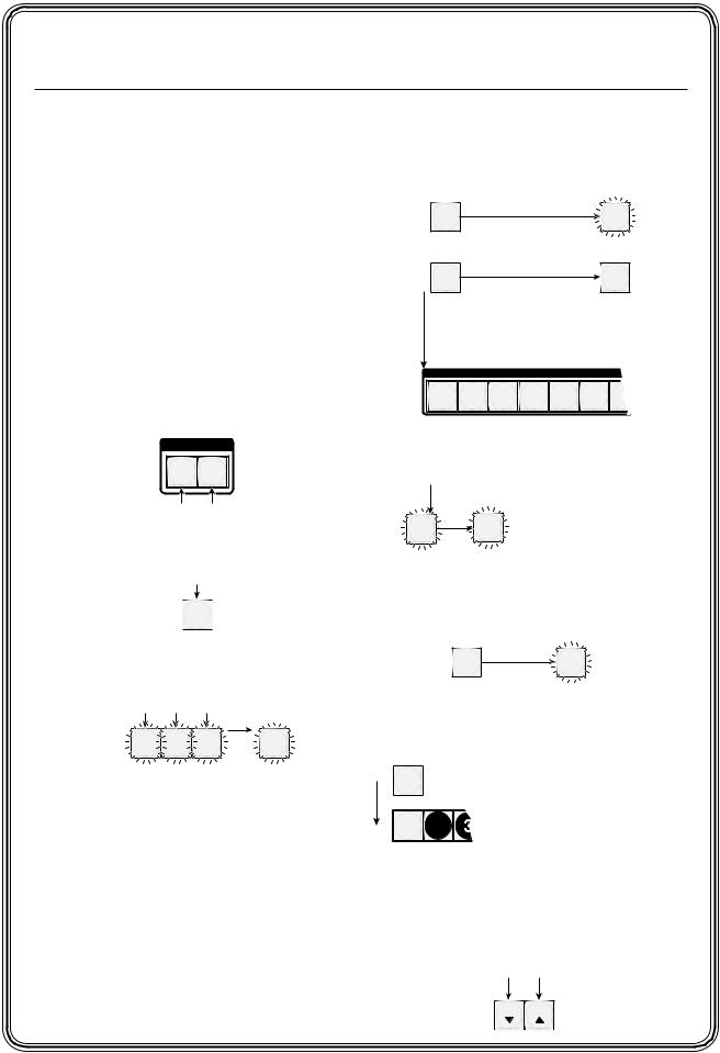
Digital Sync Validation Processing (DSVP™) — In critical environments or unmanned, remote locations, it may be vital to know that sources are active and switching. Extron’s DSVP confirms that input sources are active by scanning all sync inputs for active signals. DSVP provides instantaneous frequency feedback for composite sync or separate horizontal and vertical sync signals via the switchers’ serial port or LAN port. The frequency information can be displayed on any control system or in a Windows®-based control program on a local-area network (LAN) or Internet (IP) connection (figure 1-2).
Input # 01
|
|
Signal: PRESENT |
MATRIX INPUT STATUS |
|||
|
|
Sync Type: H&V |
|
|
|
|
|
|
Vertical Freq.: 60 Hz |
Input # 01 |
Input # 02 |
Input # 03 |
Input # 04 |
|
|
Horz Freq.: 31.5 kHz |
Signal: PRESENT |
Signal: PRESENT |
Signal: PRESENT |
Signal: PRESENT |
|
|
Vertical Freq.: 60 Hz |
Vertical Freq.: 60 Hz |
Vertical Freq.: 60 Hz |
Vertical Freq.: 60 Hz |
|
|
|
|
Sync Type: H&V |
Sync Type: H&V |
Sync Type: H&V |
Sync Type: H&V |
|
|
|
Horz Freq.: 31.5 kHz |
Horz Freq.: 31.5 kHz |
Horz Freq.: 31.5 kHz |
Horz Freq.: 31.5 kHz |
|
|
|
Input # 05 |
Input # 06 |
Input # 07 |
Input # 08 |
|
|
|
Signal: PRESENT |
Signal: PRESENT |
Signal: PRESENT |
Signal: PRESENT |
|
|
|
Sync Type: H&V |
Sync Type: H&V |
Sync Type: H&V |
Sync Type: H&V |
|
|
|
Vertical Freq.: 60 Hz |
Vertical Freq.: 60 Hz |
Vertical Freq.: 60 Hz |
Vertical Freq.: 60 Hz |
|
|
|
Horz Freq.: 31.5 kHz |
Horz Freq.: 31.5 kHz |
Horz Freq.: 31.5 kHz |
Horz Freq.: 31.5 kHz |
Input |
Horz. |
Vert. |
Input # 09 |
Input # 10 |
Input # 11 |
Input # 12 |
01 |
31.50 |
60.00 |
Signal: PRESENT |
Signal: PRESENT |
Signal: PRESENT |
Signal: PRESENT |
Horz Freq.: 31.5 kHz |
Horz Freq.: 31.5 kHz |
Horz Freq.: 31.5 kHz |
Horz Freq.: 31.5 kHz |
|||
|
|
|
Sync Type: H&V |
Sync Type: H&V |
Sync Type: H&V |
Sync Type: H&V |
|
|
|
Vertical Freq.: 60 Hz |
Vertical Freq.: 60 Hz |
Vertical Freq.: 60 Hz |
Vertical Freq.: 60 Hz |
02 |
31.50 |
60.00 |
|
|
|
|
03 |
31.50 |
60.00 |
|
|
|
|
04 |
48.01 |
67.50 |
Sample control system panel |
|||
05 |
48.01 |
67.50 |
|
OR |
|
|
06 |
48.01 |
67.50 |
|
|
|
|
07 |
48.01 |
67.50 |
|
|
|
|
08 |
61.55 |
72.00 |
|
|
|
|
09 |
61.55 |
72.00 |
|
|
|
|
10 |
61.55 |
72.00 |
|
|
|
|
11 |
61.55 |
72.00 |
|
|
|
|
12 |
61.55 |
72.00 |
|
|
|
|
Windows-based control program
Figure 1-2 — DSVP data display
1-4 MVX Plus 128 VGA A Matrix Switcher • Introduction

Rooming — The switcher can be programmed to group multiple outputs to specific “rooms”, allowing them to have their own presets.
Switching flexibility — Provides individually buffered, independent matrix switched outputs with audio follow and audio breakaway for audio models.
•Tie any input to any or all outputs.
•Quick multiple tie — Multiple inputs can be switched to multiple outputs simultaneously. This allows all displays (outputs) to change from source to source at the same time.
•Audio follow — Audio can be switched with its corresponding video input via front panel control or under Ethernet or serial port remote control.
•Audio breakaway — Audio can be broken away from its corresponding video signal. This feature allows any audio signal to be selected with any video signal simultaneously to one or all outputs in any combination. Audio breakaway switching can be done via front panel control or under Ethernet or serial port remote control.
Operational flexibility — Operations such as input/output selection, setting of presets, and adjustment of audio levels can be performed on the front panel or via the Ethernet or either serial port link. The serial ports allow remote control via a PC or a control system. The Ethernet link allows multiple remote links with two levels of password protection.
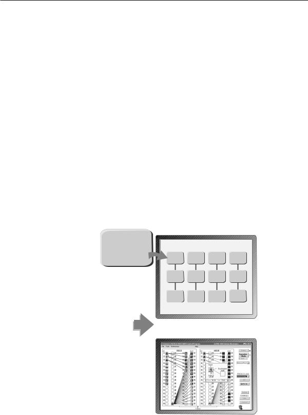
•Front Panel Controller — The front panel controller supports input and output selection, I/O grouping, preset creation and selection, RGB delay, and audio gain and attenuation, and volume control (audio models). The front panel features illuminated pushbuttons that can be labeled with text or graphics.
•Windows-based control program — For Ethernet or serial port remote control from a PC, the Extron Windows-based control software provides a graphical interface and drag-and-drop/point-and-click operation. The
Windows-based control program also has an emulation mode that lets you create a switcher configuration file at the home office and then download it for use by the switcher on site.
•Simple Instruction Set (SIS™) — The remote control protocol uses Extron’s SIS for easy programming and operation.
•Remote control panels and keypads — The matrix switchers are remote controllable, using the optional MKP 2000 and MKP 3000 remote control keypads. The remote control devices are easy to use and provide tactile buttons for quick selection. Each MKP can be used for input-to-output switching, one-touch switching for a particular output. The MKP 3000 also can be used for selection of global presets.
Upgradeable firmware — The firmware that controls all switcher operation can be upgraded in the field via RS-232/RS-422 or Ethernet, without taking the switcher out of service. Firmware upgrades are available for download on the Extron Web site, www.extron.com, and can be installed using the Windows-based control program or the built-in HTML pages.
Labeling — Extron’s included button label software lets you create labels to place in the front panel I/O buttons, with names, alphanumeric characters, or color bitmaps for easy and intuitive input and output selection. Alternatively, labels can be made with any Brother™ P-Touch™ or comparable labeler.
PRELIMINARY
MVX Plus 128 VGA A Matrix Switcher • Introduction 1-5

PRELIMINARY
Introduction, cont’d
Global memory presets — Input/output configurations can be stored in any of 32 global memory presets. You can then recall those configurations, when needed, with a few simple steps using the front panel. For the
MVX Plus 128 VGA A, 20 global memory presets are available from the front panel; the remaining presets are available via serial port control.
Rack mounting — Rack mountable in any conventional 19" wide rack
Three front panel security lockout modes (Executive modes) — If a matrix switcher is installed in an open area, where operation by unauthorized personnel may be a problem, either of two security lockout modes can be implemented (the third mode is unlocked). When a front panel locked mode is enabled, a special button combination or SIS command is required to unlock the front panel controller and make the front panel fully operational.
I/O grouping — This feature allows the matrix to be virtually divided into smaller sub-switchers, making installation and control easier. I/O grouping allows specific inputs and outputs, such as those designated for a specific purpose, to be grouped together. I/O grouping limits the selection of inputs and outputs to members of the same group.
Power — The matrix switcher’s 100 VAC to 240 VAC, autoswitchable, internal power supply provides worldwide power compatibility.
1-6 MVX Plus 128 VGA A Matrix Switcher • Introduction


 MVX Plus 128 VGA A Matrix Switcher
Chapter2Two
Installation
PRELIMINARY
Mounting the Switcher
Rear Panel Cabling and Views
Front Panel Configuration Port

PRELIMINARY
Installation
Mounting the Switcher
UL requirements
The following Underwriters Laboratories (UL) requirements pertain to the installation of the MVX Plus 128 VGA A into a rack.
1.Elevated operating ambient temperature — If the equipment installed in a closed or multi-unit rack assembly, the operating ambient temperature of the rack environment may be greater than room ambient temperature. Therefore, install the MVX Plus in an environment compatible with the maximum ambient temperature (Tma = +122 °F, +50 °C) specified by Extron.
2.Reduced air flow — Install the equipment in a rack so that the amount of air flow required for safe operation of the equipment is not compromised.
3.Mechanical loading — Mount the equipment in the rack so that a hazardous condition is not achieved due to uneven mechanical loading.
4.Circuit overloading — Connect the equipment to the supply circuit and consider the effect that circuit overloading might have on overcurrent protection and supply wiring. Appropriate consideration of equipment nameplate ratings should be used when addressing this concern.
5.Reliable earthing (grounding) — Maintain reliable grounding of rackmounted equipment. Pay particular attention to supply connections other than direct connections to the branch circuit (e.g. use of power strips).
Mounting instructions
The matrix switcher is housed in rack-mountable, 2U high metal enclosure with mounting flanges for a standard 19" rack. If desired, rack mount the switcher as follows:
1. |
Insert the switcher into the rack, aligning the holes in the mounting bracket |
|
with those in the rack. |
2. |
Secure the switcher to the rack using the supplied bolts. |
2-2 MVX Plus 128 VGA A Matrix Switcher • Installation
Rear Panel Cabling and Views
Figure 2-1 shows the MVX Plus 128 VGA A.
1 |
2 |
|
|
|
|
COMPUTER IN |
|
|
|
|
|
|
|
|
|
|
COMPUTER OUT |
|
|
|
|
|
|
|
|
1 |
3 |
|
5 |
|
7 |
|
9 |
|
11 |
|
|
|
1 |
3 |
|
|
5 |
|
7 |
|
|
RESET |
7 |
|
|
|
|
|
|
|
|
|
|
|
|
|
|
|
|
|
|
|
|
|
|
6 |
|
2 |
4 |
|
6 |
|
8 |
|
10 |
|
12 |
|
|
|
2 |
4 |
|
|
6 |
|
8 |
|
LAN |
|
|
LISTED |
|
|
|
|
|
|
|
|
|
|
|
|
|
|
|
|
|
|
|
|
|
|
|
1T23 |
|
|
|
|
|
|
|
|
|
|
|
|
|
|
|
|
|
|
|
|
|
|
|
I.T.E. |
|
|
|
|
|
|
|
|
|
|
|
|
|
|
|
|
|
|
|
|
REMOTE |
RS232/RS422 |
|
|
|
|
|
|
|
INPUTS |
|
|
|
|
|
|
|
|
OUTPUTS |
|
|
|
|
|
5 |
||
1 |
2 |
3 |
4 |
5 |
6 |
7 |
8 |
9 |
10 |
11 |
12 |
1 |
2 |
3 |
4 |
5 |
6 |
7 |
|
8 |
|
|
|
8 |
3 |
4 |
Figure 2-1 — MVX Plus 128 VGA A video and audio matrix switcher
CUse Electrostatic discharge precautions (be electrically grounded) when making connections. Electrostatic discharge (ESD) can damage equipment, even if you cannot feel, see, or hear it.
C Remove system power before making all connections.
Video connections
NThe switcher does not alter the video signal in any way. The signal output by the switcher is in the same format as the input.
NThe MVX Plus 128 switcher can also switch RGBS, RGsB, RsGsBs, component video, S-video, or composite video by using the appropriate adapters.
A |
RGB video inputs — Connect the analog computer-video sources to these |
|
15-pin HD female connectors. |
NMost laptop or notebook computers have an external video port, but they require special commands to output the video to that connector. Also, a laptop’s screen shuts off once the external video port is activated. See the computer’s user’s guide for details, or contact Extron for a list of common laptop keyboard commands.
B |
RGB video outputs — Connect RGBHV video displays to these 15-pin HD |
|
female connectors for each output. |
PRELIMINARY
MVX Plus 128 VGA A Matrix Switcher • Installation 2-3
PRELIMINARY
Installation, cont’d
Audio connections
By default, the audio ties follow the video ties. Audio breakaway, which can be activated via the front panel or under Ethernet or serial port control, allows you to select from any one of the audio input sources and route it separately from its
corresponding video source. See chapter 3, “Operation”, chapter 4, “Programmer’s Guide”, chapter 5, “Matrix Software”, and chapter 6, “HTML Operation” for details.
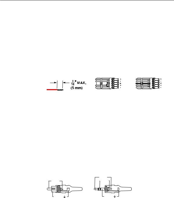
C |
Connections for balanced and unbalanced audio inputs — Each input has |
|
a 3.5 mm, 5-pole captive screw connector for balanced or unbalanced stereo |
|
audio input. Connectors are included with each switcher, but you must |
|
supply the audio cable. See figure 2-2 to wire a connector for the appropriate |
|
input type and impedance level. Use the supplied tie-wrap to strap the audio |
|
cable to the extended tail of the connector. High impedance is generally over |
|
800 ohms. |
Tip |
L |
Tip |
L |
|
Sleeve |
Ring |
|||
|
|
|||
|
|
Sleeve (s) |
|
|
Tip |
R |
Tip |
R |
|
Sleeve |
Ring |
|||
|
|
Do not tin the wires! |
Unbalanced Stereo Input |
Balanced Stereo Input |
|
(high impedance) |
(high impedance) |
||
|
Figure 2-2 — Captive screw connector wiring for audio inputs
CThe length of the exposed (stripped) portion of the copper wires is important. The ideal length is 3/16” (5 mm). Longer bare wires can short together. Shorter bare wires are not as secure in the direct insertion connectors and could be pulled out.
CThe captive screw audio connector can easily be inadvertently plugged partially into one receptacle and partially into an adjacent receptacle. This misconnection could damage the audio output circuits. Ensure that the connector is plugged fully and only into the desired input or output.
NSee figure 2-3 to identify the tip, ring, and sleeve parts of the connector when you are making connections for the switcher from existing audio cables. A mono audio connector consists of a tip and sleeve. A stereo audio connector consists of a tip, ring and sleeve. The ring, tip, and sleeve wires are also shown on the captive screw audio connector diagrams, figure 2-2 and figure 2-4.
|
Tip (+) |
|
Tip (+) |
Ring (-) |
|
Sleeve ( ) |
Sleeve ( ) |
|
RCA Connector |
3.5 mm Stereo Plug Connector |
|
(balanced) |
||
|
Figure 2-3 — Typical audio connectors
The audio level for each input can be individually set via the front panel or Ethernet or RS-232/RS-422 control to ensure that the level on the output does not vary from input to input. See chapter 3, “Operation”, chapter 4,
“Programmer’s Guide”, chapter 5, “Matrix Software”, and chapter 6, “HTML Operation” for details.
2-4 MVX Plus 128 VGA A Matrix Switcher • Installation
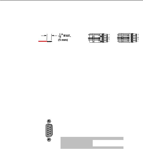
D |
Connections for balanced and unbalanced audio outputs — These |
|
3.5 mm, 5-pole captive screw connectors output the selected unamplified, |
|
line level audio. Connect audio devices, such as an audio amplifier or |
|
powered speakers. See figure 2-4 to properly wire an output connector. Use |
|
the supplied tie-wrap to strap the audio cable to the extended tail of the |
|
connector. |
Tip |
Tip |
L |
|
NO GROUND HERE. |
Ring |
||
|
|||
Sleeve(s) |
Sleeve(s) |
|
|
Tip |
Tip |
R |
|
NO GROUND HERE. |
Ring |
||
|
Do not tin the wires! |
Unbalanced Stereo Output |
Balanced Stereo Output |
Figure 2-4 — Captive screw connector wiring for audio output
CConnect the sleeve to ground (Gnd). Connecting the sleeve to a negative (-) terminal will damage the audio output circuits.
CThe length of the exposed (stripped) portion of the copper wires is important. The ideal length is 3/16” (5 mm). Longer bare wires can short together. Shorter bare wires are not as secure in the direct insertion connectors and could be pulled out.
The volume level for each output can be individually set via the front panel or Ethernet or serial port control. See chapter 3, “Operation”, chapter 4, “Programmer’s Guide”, chapter 5, “Matrix Software”, and chapter 6, “HTML Operation” for details.
RS-232/RS-422 connection
E |
RS-232/RS-422 connector — Connect a host device, such as a computer, |
|
touch panel control, or RS-232 capable PDA to the switcher via this 9-pin D |
|
connector for serial RS-232/RS-422 control (figure 2-5). |
REMOTE
1 |
6 |
RS232/RS422 |
|
||
|
|
5 |
9 |
|
Pin |
RS-232 |
Function |
RS-422 |
Function |
1 |
— |
Not used |
— |
Not used |
2 |
TX |
Transmit data |
TX– |
Transmit data (–) |
3 |
RX |
Receive data |
RX– |
Receive data (–) |
4 |
— |
Not used |
— |
Not used |
5 |
Gnd |
Signal ground |
Gnd |
Signal ground |
6 |
— |
Not used |
— |
Not used |
7 |
— |
Not used |
RX+ |
Receive data (+) |
8 |
— |
Not used |
TX+ |
Transmit data (+) |
9 |
— |
Not used |
— |
Not used |
Figure 2-5 — RS-232/RS-422 connector
See chapter 4, “Programmer’s Guide”, for definitions of the SIS commands (serial commands to control the switcher via this connector) and chapter 5, “Matrix Software”, for details on how to install and use the control software.
NThe switcher can support either the RS-232 or RS-422 serial communication protocol, and can operate at 9600, 19200, 38400, or 115200 baud rates.
See “Selecting the rear panel Remote port protocol and baud rate” in chapter 3, “Operation”, to configure the RS-232/RS-422 port from the front panel.
If desired, connect an MKP 2000 or MKP 3000 remote control panel to the switcher’s RS-232/RS-422 connector. Refer to the MKP 2000 Remote Control Panel User’s Manual and the MKP 3000 User’s Manual for details.
PRELIMINARY
MVX Plus 128 VGA A Matrix Switcher • Installation 2-5

PRELIMINARY
Installation, cont’d
Ethernet connection
F LAN port
 Activity Link
— If desired, for IP control of the system, connect the matrix
LED |
switcher to a PC or to an Ethernet LAN, via this RJ-45 connector. |
|
You can use a PC to control the networked switcher with SIS |
||
|
||
LED |
commands from anywhere in the world. You can also control |
|
the switcher from a PC that is running Extron’s Windows-based |
||
|
||
|
control program or has downloaded HTML pages from the |
|
|
switcher. |
Ethernet connection indicators — The Link and Act LEDs indicate the status of the Ethernet connection. The Link LED indicates that the switcher is properly connected to an Ethernet LAN. This LED should light steadily. The Act LED indicates transmission of data packets on the RJ-45 connector. This LED should flicker as the switcher communicates.
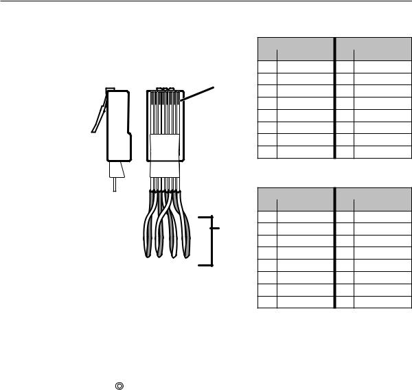
Cabling and RJ-45 connector wiring
It is vital that your Ethernet cables be the correct cable type, and that they be properly terminated with the correct pinout. Ethernet links use Category (CAT) 5e or CAT 6, unshielded twisted pair (UTP) or shielded twisted pair (STP) cables, terminated with RJ-45 connectors. Ethernet cables are limited to a length of 328’ (100 m).
NDo not use standard telephone cables. Telephone cables do not support Ethernet or Fast Ethernet.
Do not stretch or bend cables. Transmission errors can occur.
The cable used depends on your network speed. The switcher supports both 10 Mbps (10Base-T — Ethernet) and 100 Mbps (100Base-T — Fast Ethernet), half-duplex and full-duplex Ethernet connections.
•10Base-T Ethernet requires CAT 3 UTP or STP cable at minimum.
•100Base-T Fast Ethernet requires CAT 5e UTP or STP cable at minimum.
The Ethernet cable can be terminated as a straight-through cable or a crossover cable and must be properly terminated for your application (figure 2-6).
•Crossover cable — Direct connection between the computer and the MVX Plus 128 VGA A switcher
•Patch (straight) cable — Connection of the MVX Plus 128 VGA A switcher to an Ethernet LAN
2-6 MVX Plus 128 VGA A Matrix Switcher • Installation
Patch (straight) cable
|
|
|
|
|
Side 1 |
|
Side 2 |
|
|
|
|
|
Pin |
Wire color |
Pin |
Wire color |
|
|
|
|
|
1 |
White-orange |
1 |
White-orange |
|
Side |
Clip Down |
|
2 |
Orange |
2 |
Orange |
||
Pins |
12345678 |
RJ-45 |
||||||
3 |
White-green |
3 |
White-green |
|||||
|
|
|
||||||
|
|
|
connector |
|||||
|
|
|
|
4 |
Blue |
4 |
Blue |
|
|
|
|
|
5 |
White-blue |
5 |
White-blue |
|
|
|
|
|
6 |
Green |
6 |
Green |
|
|
|
|
|
7 |
White-brown |
7 |
White-brown |
|
|
|
|
|
8 |
Brown |
8 |
Brown |
|
|
|
12345678 |
|
|
Crossover cable |
|||
|
|
|
|
|
||||
|
|
|
|
|
Side 1 |
|
Side 2 |
|
|
|
|
|
Pin |
Wire color |
Pin |
Wire color |
|
|
|
|
|
1 |
White-orange |
1 |
White-green |
|
|
|
|
Twisted |
2 |
Orange |
2 |
Green |
|
|
|
|
Pairs |
3 |
White-green |
3 |
White-orange |
|
|
|
|
|
|||||
1&2 |
|
|
7&8 |
4 |
Blue |
4 |
Blue |
|
|
|
3&6 4&5 |
|
5 |
White-blue |
5 |
White-blue |
|
|
|
|
|
|||||
|
|
|
|
6 |
Green |
6 |
Orange |
|
|
|
|
|
7 |
White-brown |
7 |
White-brown |
|
|
|
|
|
8 |
Brown |
8 |
Brown |
|
Figure 2-6 — RJ-45 connector and pinout tables
Reset button
G Reset button — The Reset button initiates four levels of reset to the matrix |
|
RESET |
switcher. For two different reset levels, press and hold the button while |
|
the switcher is running or while you power up the switcher. |
See “Rear Panel Controls” in chapter 3, “Operation”, for details.
•Events (mode 3) reset — Hold Reset for 3 seconds, then release it and push it again to toggle events monitoring on and off.
•IP settings (mode 4) reset — Hold Reset for 6 seconds, then release it and push it again to reset the switcher’s IP functions.
N The IP settings reset does not replace any user-installed firmware.
•Absolute (mode 5) reset — Hold Reset for 9, seconds then release it and push it again to restore the switcher to the default factory conditions.
•Hard reset — Hold Reset while powering up the switcher to restore the switcher to the default factory conditions.
N Hard reset does not clear the current configuration.
Power connection
H |
AC power connector — Plug a standard IEC power cord into this connector to |
|
connect the switcher to a 100 VAC to 240 VAC, 50 or 60 Hz power source. |
MVX Plus 128 VGA A Matrix Switcher • Installation 2-7
PRELIMINARY
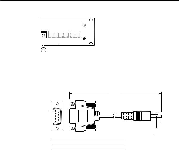
PRELIMINARY
Installation, cont’d
Front Panel Configuration Port
CONFIG |
CONTROL |
|
|
I/O |
|
ENTER |
PRESET |
VIEW |
ESC |
VIDEO |
AUDIO |
MVX PLUS SERIES
VGA MATRIX SWITCHER WITH IP LINK™
9
Figure 2-7 — Front panel configuration port
I |
Configuration port — This 2.5 mm mini stereo jack serves the same serial |
|||
|
communications function as the rear panel Remote port, but is easier to access |
|||
|
than the rear port after the matrix switcher has been installed and cabled. |
|||
|
The optional 9-pin D to 2.5 mm mini jack TRS RS-232 cable, part #70-335-01 |
|||
|
(figure 2-8), can be used for this connection. |
|
||
|
|
|
6 feet |
|
|
|
|
(1.8 m) |
|
|
1 |
6 |
Part #70-335-01 |
|
|
|
|
||
|
|
|
|
|
|
5 |
9 |
|
|
|
|
|
Tip |
|
|
|
|
|
|
|
|
|
|
Ring |
|
9-pin D |
Connection |
TRS Plug |
Sleeve (Gnd) |
|
|
|||
|
Pin 2 |
Computer's RX line |
Tip |
|
|
Pin 3 |
Computer's TX line |
Ring |
|
|
Pin 5 Computer's signal ground |
Sleeve |
|
|
Figure 2-8 — Optional 9-pin TRS RS-232 cable
NThis port is independent of the rear panel Remote port and is not affected by changes to the rear panel port’s protocol. This front panel port’s protocol can be changed, under SIS command control only. See the Command/Response table for IP SIS commands, in chapter 4, “Programmer’s Guide”, to configure all ports under SIS control.
NA front panel Configuration port connection and a rear panel Remote port connection can both be active at the same time.
The Configuration port is RS-232 only, with its default protocols as follows:
• |
9600 baud |
• |
no parity |
• 8 data bits |
• |
1 stop bit |
• |
no flow control |
|
NThe maximum distances from the matrix switcher to the controlling device can vary up to 200 feet (61 m). Factors such as cable gauge, baud rates, environment, and output levels (from the switcher and the controlling device) all affect transmission distance. Distances of about 50 feet (15 m) are typically not a problem. In some cases the matrix switcher may be capable of serial communications via RS-232 up to 250 feet (76 m) away.
2-8 MVX Plus 128 VGA A Matrix Switcher • Installation


 MVX Plus 128 VGA A Matrix Switcher
Chapter3Three
Operation
PRELIMINARY
Front Panel Controls .and Indicators
Front Panel Operations
Rear Panel Operations
Optimizing the Audio
Troubles hooting
Configuration Works heets
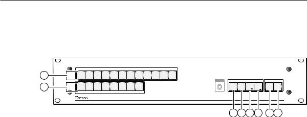
PRELIMINARY
Operation
Front Panel Controls and Indicators
The front panel controls (figure 3-1) are grouped into two sets. The input and output buttons are grouped on the left side of the control panel. The control buttons and video/audio (I/O) selection buttons are grouped on the right side of the panel.
|
|
|
|
|
|
INPUTS |
|
|
|
|
|
|
|
1 |
1 |
2 |
3 |
4 |
5 |
6 |
7 |
8 |
9 |
10 11 12 |
|
|
|
2 |
1 |
2 |
3 |
4 |
5 |
6 |
7 |
8 |
|
CONFIG |
CONTROL |
|
I/O |
|
ENTER |
PRESET VIEW |
ESC |
VIDEO AUDIO |
|||||||||
|
|
|
|
OUTPUTS |
|
|
|
|
|
|
|
|
|
|
|
|
|
|
|
|
|
|
|
|
|
|
MVX PLUS SERIES |
|
|
|
|
|
|
|
|
|
|
|
|
VGA MATRIX SWITCHER WITH IP LINK™ |
|
3 4 5 6 7 8
Figure 3-1 — Front panel, MVX Plus 128 VGA A
The large, illuminated pushbuttons can be labeled with text and/or graphics. The buttons can be set to provide amber background illumination all the time or the background illumination can be turned off (see “Background illumination”, on page 3-43. The buttons blink or are lit at full intensity (depending on the operation) when selected.
Definitions
The following terms, which apply to Extron matrix switchers, are used throughout this manual:
Tie — An input-to-output connection.
Set of ties — An input tied to two or more outputs. (An output can never be tied to more than one input.)
Configuration — One or more ties or one or more sets of ties.
Current configuration — The configuration that is currently active in the switcher (also called configuration 0)
Global memory preset — A configuration that has been stored. Up to 32 global memory presets can be stored in memory. Preset locations are assigned to the input buttons and output buttons. When a preset is retrieved from memory, it becomes the current configuration.
The switchers have 32 presets. Up to 20 presets can be selected from the front panel for either saving or retrieving. Preset numbers larger than 20 are accessible via serial port or LAN port control.
Room — A subset of outputs that are logically related to each other, as determined by the operator. The switchers support up to 10 rooms, each of which can consist of from 1 to 16 outputs.
Room memory preset — A configuration consisting of outputs in a single room that has been stored. When a room preset is retrieved from memory, it becomes the current configuration.
3-2 MVX Plus 128 VGA A Matrix Switcher • Operation

Input and output buttons
A |
Input buttons — The input buttons have two primary functions (•) and five |
|
|
secondary functions ( ): |
|
|
• |
Select an input. |
|
• |
Identify the selected input. |
|
|
(Input 1 only) With the Output 1 button, select I/O Group mode. See |
|
|
“I/O grouping” on page 3-19. |
|
|
Select a preset. See “Using presets” on page 3-26. |
|
|
Display the RGB delay. See “Setting RGB delay” on page 3-23. |
|
|
Display the output volume level. See “Viewing and adjusting the output |
|
|
volume” on page 3-36. |
|
|
(Input 1 and Input 2 only) Toggle background illumination of the buttons |
|
|
on and off. See “Background illumination” on page 3-43. |
B |
Output buttons — The output buttons have two primary functions (•) and |
|
|
four secondary functions ( ): |
|
|
• |
Select output(s). |
|
• |
Identify the selected output(s). |
|
|
(Output 1 only) With the Input 1 button, select I/O Group mode. See |
|
|
“I/O grouping” on page 3-19. |
|
|
Select a preset. See “Using presets” on page 3-26. |
|
|
Mute the output. See “Muting and unmuting video and/or audio |
|
|
outputs” on page 3-29. |
|
|
Display the audio level of the selected input. See “Viewing and adjusting |
|
|
the input audio level” on page 3-32. |
PRELIMINARY
MVX Plus 128 VGA A Matrix Switcher • Operation 3-3

PRELIMINARY
Operation, cont’d
Control buttons
C Enter button — The Enter button has three primary functions (•) and six secondary functions ( ):
|
• |
Save changes that you make on the front panel. To create a simple |
|
|
configuration: |
|
|
Specify RGBHV, audio, or both (see I/O selection buttons [G] and |
|
|
[H]). |
|
|
Press the desired input button (A). |
|
|
Press the desired output button(s) (B). |
|
|
Press the Enter button. |
|
• |
Indicate that a potential tie has been created but not saved. |
|
• |
Indicate that a global preset has been selected to be saved or recalled but |
|
|
that the preset action has not been accomplished. |
|
|
In the I/O Group mode, select group 1. See “I/O grouping” on page 3-19. |
|
|
In the I/O Group mode, indicate that group 1 is selected. See “I/O |
|
|
grouping” on page 3-19. |
|
|
With the Preset, View, and Esc buttons, select Serial Port Configuration |
|
|
mode. See “Selecting the rear panel Remote port protocol and baud rate” |
|
|
on page 3-43. |
|
|
Select 9600 baud for the RS-232/RS-422 port in Serial Port Configuration |
|
|
mode. See “Selecting the rear panel Remote port protocol and baud rate” |
|
|
on page 3-43. |
|
|
Indicate that the RS-232/RS-422 port is set to 9600 baud in Serial Port |
|
|
Configuration mode. See “Selecting the rear panel Remote port protocol |
|
|
and baud rate” on page 3-43. |
|
|
With the RGBHV and Audio buttons, select front panel security Lock |
|
|
mode 2 or toggle between mode 0 (unlocked) and mode 2. See “Setting |
|
|
the front panel locks (Executive modes)” on page 3-41. |
D |
Preset button — The Preset button has two primary functions (•) and five |
|
|
secondary functions ( ): |
|
|
• |
Activates Save Preset mode to save a configuration as a preset and Recall |
|
|
Preset mode to activate a previously-defined preset. |
|
• |
Blinks when Save Preset mode is active and lights steadily when Recall |
|
|
Preset mode is active. |
|
|
In the I/O Group mode, select group 2. See “I/O grouping” on page 3-19. |
|
|
In the I/O Group mode, indicate that group 2 is selected. See “I/O |
|
|
grouping” on page 3-19. |
|
|
With the Enter, View, and Esc buttons, select Serial Port Configuration |
|
|
mode. See “Selecting the rear panel Remote port protocol and baud rate” |
|
|
on page 3-43. |
|
|
Select 19200 baud for the RS-232/RS-422 port in Serial Port Configuration |
|
|
mode. See “Selecting the rear panel Remote port protocol and baud rate” |
|
|
on page 3-43. |
|
|
Indicate that the RS-232/RS-422 port is set to 19200 baud in Serial Port |
|
|
Configuration mode. See “Selecting the rear panel Remote port protocol |
|
|
and baud rate” on page 3-43. |
3-4 MVX Plus 128 VGA A Matrix Switcher • Operation
Loading...