


DVS 204
Digital Video Scaler series DVS 204, DVS 204 D, DVS 204 12V, DVS 204 D 12V
68-605-01 Rev. C
01 05
Precautions
Safety Instructions • English
This symbol is intended to alert the user of important operating and maintenance (servicing) instructions in the literature provided with the equipment.
This symbol is intended to alert the user of the presence of uninsulated dangerous voltage within the product's enclosure that may present a risk of electric shock.
Caution
Read Instructions • Read and understand all safety and operating instructions before using the equipment.
Retain Instructions • The safety instructions should be kept for future reference.
Follow Warnings • Follow all warnings and instructions marked on the equipment or in the user information.
Avoid Attachments • Do not use tools or attachments that are not recommended by the equipment manufacturer because they may be hazardous.
Consignes de Sécurité • Français
Ce symbole sert à avertir l’utilisateur que la documentation fournie avec le matériel contient des instructions importantes concernant l’exploitation et la maintenance (réparation).
Ce symbole sert à avertir l’utilisateur de la présence dans le boîtier de l’appareil de tensions dangereuses non isolées posant des risques d’électrocution.
Attention
Lire les instructions• Prendre connaissance de toutes les consignes de sécurité et d’exploitation avant d’utiliser le matériel.
Conserver les instructions• Ranger les consignes de sécurité afin de pouvoir les consulter à l’avenir.
Respecter les avertissements • Observer tous les avertissements et consignes marqués sur le matériel ou présentés dans la documentation utilisateur.
Eviter les pièces de fixation • Ne pas utiliser de pièces de fixation ni d’outils non recommandés par le fabricant du matériel car cela risquerait de poser certains dangers.
Sicherheitsanleitungen • Deutsch
Dieses Symbol soll dem Benutzer in der im Lieferumfang enthaltenen Dokumentation besonders wichtige Hinweise zur Bedienung und Wartung (Instandhaltung) geben.
Dieses Symbol soll den Benutzer darauf aufmerksam machen, daß im Inneren des Gehäuses dieses Produktes gefährliche Spannungen, die nicht isoliert sind und die einen elektrischen Schock verursachen können, herrschen.
Achtung
Lesen der Anleitungen • Bevor Sie das Gerät zum ersten Mal verwenden, sollten Sie alle Sicherheits-und Bedienungsanleitungen genau durchlesen und verstehen.
Aufbewahren der Anleitungen • Die Hinweise zur elektrischen Sicherheit des Produktes sollten Sie aufbewahren, damit Sie im Bedarfsfall darauf zurückgreifen können.
Befolgen der Warnhinweise • Befolgen Sie alle Warnhinweise und Anleitungen auf dem Gerät oder in der Benutzerdokumentation.
Keine Zusatzgeräte • Verwenden Sie keine Werkzeuge oder Zusatzgeräte, die nicht ausdrücklich vom Hersteller empfohlen wurden, da diese eine Gefahrenquelle darstellen können.
Warning
Power sources • This equipment should be operated only from the power source indicated on the product. This equipment is intended to be used with a main power system with a grounded (neutral) conductor. The third (grounding) pin is a safety feature, do not attempt to bypass or disable it.
Power disconnection • To remove power from the equipment safely, remove all power cords from the rear of the equipment, or the desktop power module (if detachable), or from the power source receptacle (wall plug).
Power cord protection • Power cords should be routed so that they are not likely to be stepped on or pinched by items placed upon or against them.
Servicing • Refer all servicing to qualified service personnel. There are no user-serviceable parts inside. To prevent the risk of shock, do not attempt to service this equipment yourself because opening or removing covers may expose you to dangerous voltage or other hazards.
Slots and openings • If the equipment has slots or holes in the enclosure, these are provided to prevent overheating of sensitive components inside. These openings must never be blocked by other objects.
Lithium battery • There is a danger of explosion if battery is incorrectly replaced. Replace it only with the same or equivalent type recommended by the manufacturer. Dispose of used batteries according to the manufacturer's instructions.
Avertissement
Alimentations• Ne faire fonctionner ce matériel qu’avec la source d’alimentation indiquée sur l’appareil. Ce matériel doit être utilisé avec une alimentation principale comportant un fil de terre (neutre). Le troisième contact (de mise à la terre) constitue un dispositif de sécurité : n’essayez pas de la contourner ni de la désactiver.
Déconnexion de l’alimentation• Pour mettre le matériel hors tension sans danger, déconnectez tous les cordons d’alimentation de l’arrière de l’appareil ou du module d’alimentation de bureau (s’il est amovible) ou encore de la prise secteur.
Protection du cordon d’alimentation • Acheminer les cordons d’alimentation de manière à ce que personne ne risque de marcher dessus et à ce qu’ils ne soient pas écrasés ou pincés par des objets.
Réparation-maintenance • Faire exécuter toutes les interventions de réparation-maintenance par un technicien qualifié. Aucun des éléments internes ne peut être réparé par l’utilisateur. Afin d’éviter tout danger d’électrocution, l’utilisateur ne doit pas essayer de procéder lui-même à ces opérations car l’ouverture ou le retrait des couvercles risquent de l’exposer à de hautes tensions et autres dangers.
Fentes et orifices • Si le boîtier de l’appareil comporte des fentes ou des orifices, ceux-ci servent à empêcher les composants internes sensibles de surchauffer. Ces ouvertures ne doivent jamais être bloquées par des objets.
Lithium Batterie • Il a danger d'explosion s'll y a remplacment incorrect de la batterie. Remplacer uniquement avec une batterie du meme type ou d'un ype equivalent recommande par le constructeur. Mettre au reut les batteries usagees conformement aux instructions du fabricant.
Vorsicht
Stromquellen • Dieses Gerät sollte nur über die auf dem Produkt angegebene Stromquelle betrieben werden. Dieses Gerät wurde für eine Verwendung mit einer Hauptstromleitung mit einem geerdeten (neutralen) Leiter konzipiert. Der dritte Kontakt ist für einen Erdanschluß, und stellt eine Sicherheitsfunktion dar. Diese sollte nicht umgangen oder außer Betrieb gesetzt werden.
Stromunterbrechung • Um das Gerät auf sichere Weise vom Netz zu trennen, sollten Sie alle Netzkabel aus der Rückseite des Gerätes, aus der externen Stomversorgung (falls dies möglich ist) oder aus der Wandsteckdose ziehen.
Schutz des Netzkabels • Netzkabel sollten stets so verlegt werden, daß sie nicht im Weg liegen und niemand darauf treten kann oder Objekte daraufoder unmittelbar dagegengestellt werden können.
Wartung • Alle Wartungsmaßnahmen sollten nur von qualifiziertem Servicepersonal durchgeführt werden. Die internen Komponenten des Gerätes sind wartungsfrei. Zur Vermeidung eines elektrischen Schocks versuchen Sie in keinem Fall, dieses Gerät selbst öffnen, da beim Entfernen der Abdeckungen die Gefahr eines elektrischen Schlags und/oder andere Gefahren bestehen.
Schlitze und Öffnungen • Wenn das Gerät Schlitze oder Löcher im Gehäuse aufweist, dienen diese zur Vermeidung einer Überhitzung der empfindlichen Teile im Inneren. Diese Öffnungen dürfen niemals von anderen Objekten blockiert werden.
Litium-Batterie • Explosionsgefahr, falls die Batterie nicht richtig ersetzt wird. Ersetzen Sie verbrauchte Batterien nur durch den gleichen oder einen vergleichbaren Batterietyp, der auch vom Hersteller empfohlen wird. Entsorgen Sie verbrauchte Batterien bitte gemäß den Herstelleranweisungen.
Instrucciones de seguridad • Español
Este símbolo se utiliza para advertir al usuario sobre instrucciones importantes de operación y mantenimiento (o cambio de partes) que se desean destacar en el contenido de la documentación suministrada con los equipos.
Este símbolo se utiliza para advertir al usuario sobre la presencia de elementos con voltaje peligroso sin protección aislante, que puedan encontrarse dentro de la caja o alojamiento del producto, y que puedan representar riesgo de electrocución.
Precaucion
Leer las instrucciones • Leer y analizar todas las instrucciones de operación y seguridad, antes de usar el equipo.
Conservar las instrucciones • Conservar las instrucciones de seguridad para futura consulta.
Obedecer las advertencias • Todas las advertencias e instrucciones marcadas en el equipo o en la documentación del usuario, deben ser obedecidas.
Evitar el uso de accesorios • No usar herramientas o accesorios que no sean especificamente recomendados por el fabricante, ya que podrian implicar riesgos.
Advertencia
Alimentación eléctrica • Este equipo debe conectarse únicamente a la fuente/tipo de alimentación eléctrica indicada en el mismo. La alimentación eléctrica de este equipo debe provenir de un sistema de distribución general con conductor neutro a tierra. La tercera pata (puesta a tierra) es una medida de seguridad, no puentearia ni eliminaria.
Desconexión de alimentación eléctrica • Para desconectar con seguridad la acometida de alimentación eléctrica al equipo, desenchufar todos los cables de alimentación en el panel trasero del equipo, o desenchufar el módulo de alimentación (si fuera independiente), o desenchufar el cable del receptáculo de la pared.
Protección del cables de alimentación • Los cables de alimentación eléctrica se deben instalar en lugares donde no sean pisados ni apretados por objetos que se puedan apoyar sobre ellos.
Reparaciones/mantenimiento • Solicitar siempre los servicios técnicos de personal calificado. En el interior no hay partes a las que el usuario deba acceder. Para evitar riesgo de electrocución, no intentar personalmente la reparación/mantenimiento de este equipo, ya que al abrir o extraer las tapas puede quedar expuesto a voltajes peligrosos u otros riesgos.
Ranuras y aberturas • Si el equipo posee ranuras o orificios en su caja/alojamiento, es para evitar el sobrecalientamiento de componentes internos sensibles. Estas aberturas nunca se deben obstruir con otros objetos.
Batería de litio • Existe riesgo de explosión si esta batería se coloca en la posición incorrecta. Cambiar esta batería únicamente con el mismo tipo (o su equivalente) recomendado por el fabricante. Desachar las baterías usadas siguiendo las instrucciones del fabricante.

Quick Start — DVS 204
Installation
Step 1
Refer to the application examples at the end of this page. Turn off power to the scaler and input and output devices, and remove power cords from them.
Step 2
Install the four rubber feet on the bottom of the DVS 204 scaler, or mount the scaler in a rack.
Step 3
Attach input devices to the scaler.
Rear panel video inputs
Input 1: Composite video |
VIDEO |
|
|
|
1 |
Input 2: Composite/S-video/Component |
||
Composite Video |
S-video (Y/C) |
Component Video (R-Y, Y, B-Y) |
|
B-Y |
|
B-Y |
|
/C |
|
/C |
R-Y |
Y |
R-Y |
Y |
|
/VID |
|
/VID |
|
2 |
|
2 |
Input 3: S-video |
S-VIDEO |
|
3 |
Input 4: RGB pass-through/RGBS/ RGBcS
SDI input
Attach an SDI source to this BNC (204 D model only).
|
B-Y |
|
/C |
R-Y |
Y |
|
/VID |
|
2 |
RGB
PASS - THRU/
RGBS/RGBcvS
4
SDI
Step 4
Attach output devices to the scaler.
Rear panel video outputs
Output BNC connectors
|
RGBHV |
|
|
RGBS |
|
R |
OUTPUTS |
B |
R |
OUTPUTS |
B |
G |
G |
||||
/R-Y |
/Y |
/B-Y |
/R-Y |
/Y |
/B-Y |
H |
V |
S |
H |
V |
S |
R |
OUTPUTS |
B |
OUTPUTS |
B |
|
G |
R |
G |
|||
/R-Y |
/Y |
/B-Y |
/R-Y |
/Y |
/B-Y |
|
V |
S |
H |
V |
S |
|
RGsB |
|
Component Video (R-Y, Y, B-Y) |
||
Output 15-pin HD connector |
RGB/R-Y,Y,B-Y |
Step 5
Plug the DVS 204, and input and output devices into a grounded AC source, and turn on the input and output devices.
Step 6
Use the LCD menu screens or RS-232 programming to configure the scaler. See chapter two for installation and operation procedures, and see chapter three for programming information.
Application examples
DVS 204 D |
|
|
|
|
|
||
100-240V |
0.3A |
VIDEO |
|
SDI |
INPUTS |
OUTPUTS |
REMOTE |
|
|
B-Y |
R |
G |
B |
||
|
|
|
|
/R-Y |
/Y |
/B-Y |
|
|
|
|
/C |
|
|
|
|
|
|
|
|
|
RGB |
|
|
|
|
1 |
|
S-VIDEO |
PASS - THRU |
|
|
|
|
R-Y |
Y |
RGBcvS |
V |
RGB/R-Y,Y,B-Y |
|
|
|
|
H |
S |
|||
|
|
|
/VID |
|
|
|
|
50/60 Hz |
|
2 |
3 |
4 |
|
|
|
RS-232 Control
LCD Projector
DVD Player
VCR
Laptop Computer Plasma Display
Document Camera
DVS 204 D 12V |
|
|
|
|
|||
|
VIDEO |
|
|
INPUTS |
R |
OUTPUTS |
REMOTE |
|
B-Y |
|
SDI |
G |
B |
||
|
|
|
|
/R-Y |
/Y |
/B-Y |
|
|
|
/C |
|
|
|
|
|
|
1 |
|
|
RGB |
|
|
|
POWER |
|
S-VIDEO |
PASS - THRU |
|
|
RGB/R-Y,Y,B-Y |
|
12V 1.5A DC |
R-Y |
Y |
RGBS/RGBcvS |
H |
V |
||
|
|
|
S |
||||
|
|
/VID |
|
|
|
|
|
|
|
2 |
3 |
|
4 |
|
|
RS-232 Control
|
|
LCD Projector |
DVD Player |
|
|
VCR |
|
|
Power Supply |
Laptop Computer |
Monitor |
|
||
Document Camera |
|
|
You can connect both outputs simultaneously to two different displays. The sync format is the same for both outputs.

Quick Start — DVS 204, cont’d

Table of Contents
Chapter 1 • Introduction ...................................................................................................... |
1-1 |
About this Manual ............................................................................................................ |
1-2 |
About the DVS 204 ........................................................................................................... |
1-2 |
What is the DVS 204? ....................................................................................................... |
1-2 |
Controlling the DVS 204 digital video scaler ................................................................ |
1-2 |
Features and Options ...................................................................................................... |
1-2 |
Features .............................................................................................................................. |
1-2 |
Options and accessories ................................................................................................... |
1-3 |
Chapter 2 • Installation and Operation...................................................................... |
2-1 |
Mounting the Scaler ........................................................................................................ |
2-2 |
Tabletop/desktop placement ........................................................................................... |
2-2 |
Rack mounting .................................................................................................................. |
2-2 |
Application diagram ........................................................................................................ |
2-3 |
Rear Panel Features .......................................................................................................... |
2-4 |
Front Panel Features ........................................................................................................ |
2-7 |
Input selection buttons .................................................................................................... |
2-7 |
Picture adjustment buttons ............................................................................................. |
2-7 |
Menu button ..................................................................................................................... |
2-8 |
Next button ....................................................................................................................... |
2-8 |
LCD menu display and controls ...................................................................................... |
2-8 |
Optimizing the System for a DVD ........................................................................... |
2-8 |
Setting up a DVD source .................................................................................................. |
2-8 |
Menus, Configuration, and Adjustments ............................................................ |
2-9 |
Moving through menus by using front panel controls ............................................... |
2-9 |
Menu overview ................................................................................................................. |
2-9 |
Input Configuration ....................................................................................................... |
2-10 |
Input 2 Video Type............................................................................................................. |
2-11 |
Input 4 Video Type............................................................................................................. |
2-11 |
SDI Input (SDI IN) ............................................................................................................... |
2-11 |
Output Configuration .................................................................................................... |
2-11 |
Resolution and refresh rates ............................................................................................ |
2-12 |
Output Signal ..................................................................................................................... |
2-12 |
Sync Polarity ...................................................................................................................... |
2-12 |
H Format............................................................................................................................ |
2-13 |
Blanking Configuration ................................................................................................. |
2-13 |
Top and bottom blanking ................................................................................................. |
2-13 |
Memory Preset ................................................................................................................ |
2-13 |
Save (SAVE) memory preset ............................................................................................. |
2-14 |
Clear (CLR) memory preset ............................................................................................... |
2-14 |
Recalling a preset .............................................................................................................. |
2-15 |
Advanced Configuration ................................................................................................ |
2-15 |
Detail control ..................................................................................................................... |
2-15 |
Filter mode ........................................................................................................................ |
2-15 |
Blue mode .......................................................................................................................... |
2-16 |
DVS 204 • Table of Contents |
i |

Table of Contents, cont’d
Autoswitch (Autosw) mode .............................................................................................. |
2-16 |
Enhanced (Enh) mode ....................................................................................................... |
2-16 |
2:2 Pulldown detection (PAL Film mode detect) submenu ............................................. |
2-16 |
RGB delay (Triple Action Switching).................................................................................. |
2-16 |
Exit Menu ........................................................................................................................ |
2-17 |
Image Adjustments ........................................................................................................ |
2-17 |
Color, tint, brightness, contrast, centering, sizing ..................................................... |
2-17 |
Input Reset .......................................................................................................................... |
2-18 |
System Reset ...................................................................................................................... |
2-18 |
Front Panel Security Lockout (Executive Mode) ............................................ |
2-19 |
IR 901 Infrared Remote Control .............................................................................. |
2-20 |
Aspect ratio presets ........................................................................................................ |
2-20 |
Freezing an input ........................................................................................................... |
2-20 |
Selecting an input .......................................................................................................... |
2-20 |
Size and center ............................................................................................................... |
2-20 |
Image adjustments ......................................................................................................... |
2-20 |
Troubleshooting ............................................................................................................... |
2-21 |
Operating problems ....................................................................................................... |
2-21 |
Chapter 3 • Serial Communication ................................................................................ |
3-1 |
RS-232 Programmer’s Guide ........................................................................................ |
3-2 |
Host-to-scaler communications ....................................................................................... |
3-2 |
Scaler-initiated messages ................................................................................................... |
3-2 |
Error responses ................................................................................................................... |
3-2 |
Using the command/response tables ................................................................................. |
3-3 |
Command/response table for SIS commands..................................................................... |
3-4 |
Command/response table for special function SIS commands .......................................... |
3-7 |
Control Software for Windows ................................................................................. |
3-8 |
Installing the software ..................................................................................................... |
3-8 |
Using the control program .............................................................................................. |
3-8 |
Using the help program ................................................................................................... |
3-9 |
Appendix A • Appendix........................................................................................................ |
A-1 |
Specifications ..................................................................................................................... |
A-2 |
Part Numbers and Accessories ................................................................................. |
A-4 |
Included parts .................................................................................................................. |
A-4 |
Accessories ........................................................................................................................ |
A-4 |
Firmware Upgrade Installation................................................................................. |
A-5 |
Serial Digital Interface (SDI) Card Installation ............................................... |
A-7 |
All trademarks mentioned in this manual are the properties of their respective owners.
68-605-01 Rev. C
01 05
ii DVS 204 • Table of Contents


 DVS 204
Chapter1One
Introduction
About this Manual
About the DVS 204
Features and Options

Introduction
About this Manual
This manual discusses how to install, configure, and operate the Extron DVS 204 digital video scaler and how to operate the optional IR 901 infrared remote control (part #70-152-01).
Throughout this manual the terms “DVS”, “digital video scaler”, and “scaler” are used interchangeably to refer to the same product.
About the DVS 204
What is the DVS 204?
The DVS is a series of high performance digital video scalers that offers 56 output rates, including HDTV, and provides scaling solutions for boardrooms, conference rooms, and home theaters, as well as rental and staging applications.
The scalers come in four models, two of which offer a serial digital interface (SDI) input connector: DVS 204 (no SDI), DVS 204 D (SDI), DVS 204 12V (12 volt external power supply, no SDI), and DVS 204 D 12V (12 volt external power supply, SDI).
To enable superior scaling performance, the DVS 204 features several of Extron’s patented and patent-pending technologies, including Dynamic Motion Interpolation (DMI™) technology, and 3:2 and 2:2 pulldown detection. DMI is an advanced motion detection and compensation method that enables image enhancement with no loss of image fidelity.
The DVS 204 scales composite video, S-video, and component video up to computer-video (RGBHV/RGBS/RGsB) or HD component, which can be output to two display devices via individually buffered BNC and 15-pin HD connectors.
Controlling the DVS 204 digital video scaler
The DVS 204 can be controlled using one or more of the following methods:
•The front panel controls.
•A computer, a touch screen panel, or any other device that can send and receive the serial communications through the RS-232 port. Extron’s Simple Instruction Set (SIS™) is a set of simple keystroke commands that can be used with any such devices, and Extron’s control software for Windows provides a graphical interface for controlling the scaler from a computer.
•The optional IR 901 remote control, which has most of the front panel controls.
Features and Options
Features
Four video inputs
•Input 1 — One BNC connector on the rear panel accepts composite video.
•Input 2 — Three BNC connectors on the rear panel accept composite, component, or S-video.
•Inputs 3 — One 4-pin DIN connector accepts an S-video signal.
•Input 4 — One 15-pin HD connector accepts an RGB pass-through (RGBHV, RGBS, RGsB), RGBS, or RGBcvS video signal.
SDI video input (optional) — One BNC connector on the rear panel accepts SDI video.
1-2 DVS 204 • Introduction

Buffered video outputs — Six rear-panel BNC connectors and one VGA-type 15-pin HD connector provide connections for RGB output. Both outputs (the BNCs or the 15-pin HD connector) are active at all times for simultaneous output.
Three ways to control the scaler — The scaler’s front panel, a computer or other RS-232 control device, or the optional IR 901 remote control can all be used to control the scaler.
Scaled outputs — The DVS 204 offers 59 different output rates.
RS-232 configuration — The DVS 204 can be configured by using the Extron control software for Windows, or by using a third party control system.
Accu-RATE Frame Lock™ — The Extron Accu-RATE Frame Lock™ eliminates artifacts from scaled motion video by eliminating frame rate conversion. It locks the output frame rate to the input frame rate of the active input. The result is a switching system that eliminates image tears and other artifacts from motion video.
Dynamic Motion Interpolation™ (DMI™) — This video processing technique is an advanced motion prediction and compensation method that treats motion content and still content with different algorithms to yield high fidelity images.
3:2 pulldown detection for NTSC and 2:2 film detection for PAL video sources
— These advanced film mode processing features help maximize image detail and sharpness for video sources that originated from film. When film is converted to NTSC video, the film frame rate has to be matched to the video frame rate in a process called 3:2 pulldown. Jaggies and other image artifacts can result if conventional deinterlacing techniques are used on film-source video. The DVS 204’s advanced film mode processing recognizes signals that originated from film. The DVS 204 then applies video processing algorithms that optimize the conversion of video that was made with the 3:2 pulldown process. This results in richly detailed images with sharply defined lines. A similar process is used for PAL film-source video.
Versatile mounting options — The DVS 204 is 1U high, and a half rack wide. It is rack mountable, or it can be placed on a table or other furniture. Rubber feet are included.
Options and accessories
The DVS 204’s optional equipment includes:
•IR 901 remote control — Extron’s IR 901 (part #70-152-01) is an infrared remote control which replicates all of the front panel controls of the DVS 204 except the Menu and Next buttons.
•SDI input card — Serial digital interface (SDI) input can be added to the DVS 204 model by the installation of an SDI input card (part #70-168-01).
•Rack shelf mounting kit — The 1U high, half rack width DVS 204 can be rack mounted using the rack shelf mounting kit (part #60-190-01).
DVS 204 • Introduction |
1-3 |

Introduction, cont’d
1-4 DVS 204 • Introduction

 DVS 204
Chapter2Two
Installation and Operation
Mounting the Scaler
Rear Panel Features
Front Panel Features
Optimizing the System for a DVD
Menus, Configuration, and Adjustments
Image Adjustments
Input Reset
System Reset
Front Panel Security Lockout (Executive Mode)
IR 901 Infrared Remote Control
Troubleshooting
Installation and Operation
Mounting the Scaler
Tabletop/desktop placement
For tabletop or desktop placement only, install the self-adhesive rubber feet/pads (provided) onto the four corners of the bottom of the enclosure.
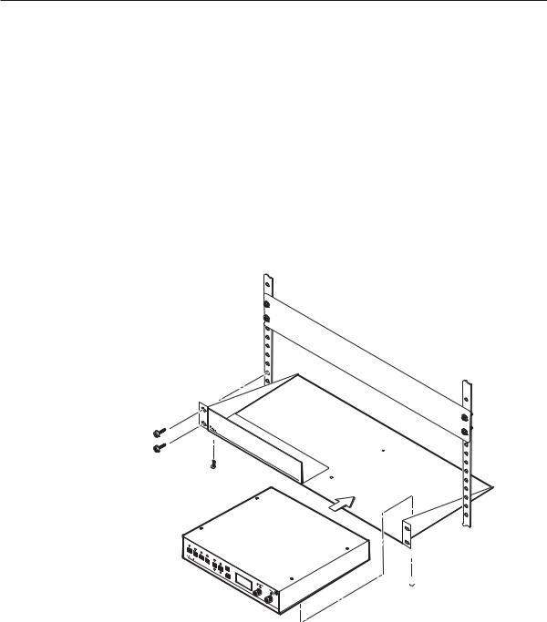
Rack mounting
1. If feet were installed on the bottom of the DVS 204, remove them.
2. Place the DVS 204 on one half of the 1U (one unit high, one unit wide) rack shelf (part #60-190-01). Align the front of the DVS 204 with the front of the shelf, and align the threaded holes on the bottom of the DVS 204 with the holes in the rack shelf.
3. Attach the DVS to the rack shelf with the two provided 4-40 x 3/16" machine screws. Insert the screws from the underside of the shelf, and securely fasten them into diagonally-opposite corners.
False front panel uses 2 front holes.
1 |
|
|
|
|
2 |
|
|
COMPOSITE |
3 |
|
|
4 |
|
|
|
|
YUV |
COL/TNT |
|
|
S-V |
CENTER |
|
|
IDEO |
|
|
|
RGB |
|
MENU |
|
|
BRT/C |
|
|
|
ONT |
SIZE |
|
|
|
|
|
|
|
NEXT |
ADJ |
|
|
|
UST |
|
|
|
|
|
|
IR |
DIG |
DVS |
|
|
ITAL V |
204 |
||
|
IDEO |
|
|
|
|
SCALER |
|
Rack mounting the DVS 204
 (2) 4-40 x 3/16" Screws
Use 2 mounting holes on opposite corners.
4. Attach the false front panel (provided with the rack shelf) to the unoccupied side of the rack (as shown above), or install a second half- rack-width device in that side by repeating steps 1–3.
5. Attach the rack shelf to the rack using four 10-32 x ¾" bolts (provided). Insert the bolts through #10 beveled washers, then through the holes in the rack ears and rack, as shown above.
2-2 DVS 204 • Installation and Operation
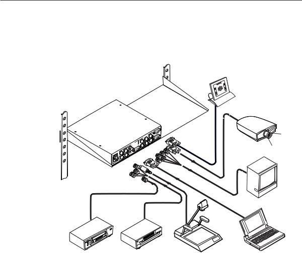
Application diagram
The diagram shown below is an example of a typical DVS 204 application with cable connections.
RS-232 Control
|
S |
|
OUTPUT |
|
G |
|
R |
TS |
V |
INPU |
|
SDI |
H |
|
B-Y |
|
/C |
VIDEO |
|
|
Y |
1 |
3 |
R-Y |
2 |
B
S
LCD Projector
DVS 204
Monitor
VCR |
DVD Player |
Document Camera Laptop Computer |
Application diagram example of the DVS 204
DVS 204 • Installation and Operation |
2-3 |
Installation and Operation
Rear Panel Features
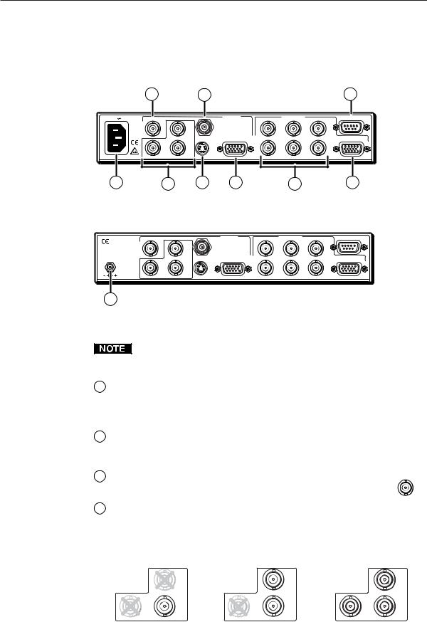
The rear panels of the DVS 204 D and DVS 204 D 12V models, as shown below, contain all of the possible connectors available on the DVS 204 series of scalers (the DVS 204 and DVS 12V models do not come with an SDI input connector).
|
2 |
5 |
|
|
9 |
100-240V 0.3A |
VIDEO |
SDI |
INPUTS |
OUTPUTS |
REMOTE |
R |
G |
B |
|||
|
|
B-Y |
/R-Y |
/Y |
/B-Y |
|
|
/C |
|||
|
|
|
|
|
|
|
1 |
|
RGB |
|
|
|
S-VIDEO |
PASS - THRU/ |
|
RGB/R-Y,Y,B-Y |
|
|
R-Y |
RGBS/RGBcvS |
V |
||
|
Y |
H |
S |
||
|
|
/VID |
|
|
|
50/60 Hz |
2 |
|
3 |
4 |
|
1 |
3 |
4 |
6 |
7 |
8 |
DVS 204 D rear panel connectors
|
VIDEO |
|
|
INPUTS |
R |
OUTPUTS |
REMOTE |
|
B-Y |
|
SDI |
G |
B |
||
|
|
|
|
/R-Y |
/Y |
/B-Y |
|
|
|
/C |
|
|
|||
|
|
|
|
|
|
|
|
|
1 |
|
|
RGB |
|
|
|
POWER |
|
S-VIDEO |
PASS - THRU |
|
|
RGB/R-Y,Y,B-Y |
|
12V 1.5A DC |
R-Y |
Y |
RGBS/RGBcvS |
H |
V |
||
|
|
|
S |
||||
|
|
/VID |
|
|
|
|
|
|
|
2 |
3 |
|
4 |
|
|
1a
DVS 204 D 12V rear panel power connector
The rear panel connectors of the 12V DC models are identical to those of the
AC models, except for the 12 volt power input connector.
1AC power connector — Plug a standard IEC power cord into this connector to connect the scaler to a 100 to 240 VAC, 50 Hz or 60 Hz power source. The front panel control and input selection LEDs will light during power-up.
1a 12V DC power connector — Plug the included 12 V power supply into this input jack (DVS 204 12V and DVS 204 D 12V models only). The front panel control and input selection LEDs will light during power-up.
2
3
Video input 1: Composite video — A composite video signal is |
VIDEO |
input through the female BNC connector. |
|
1
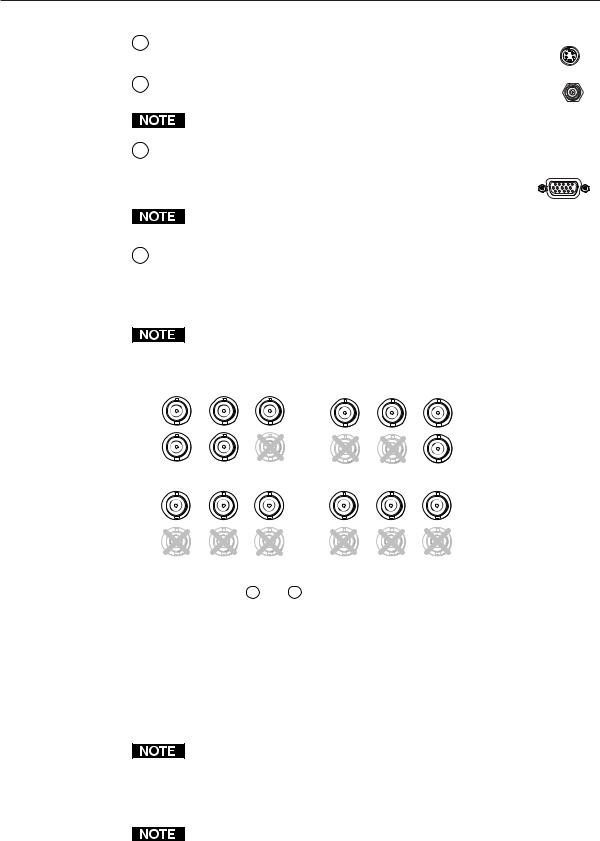
Video input 2: Composite/S-video/Component — This input, consisting of 3 female BNC connectors, accepts composite video, S-video, and component video signals. Connect cables for the appropriate signal type, as shown here.
Composite Video |
S-video (Y/C) |
|
Component Video (R-Y, Y, B-Y) |
||
|
B-Y |
|
B-Y |
|
B-Y |
|
/C |
|
/C |
|
/C |
R-Y |
Y |
R-Y |
Y |
R-Y |
Y |
|
/VID |
|
/VID |
|
/VID |
|
2 |
|
2 |
|
2 |
2-4 DVS 204 • Installation and Operation
4Video input 3: S-video — Connect an S-video signal to this 4-pin mini-DIN female connector.
5SDI (serial digital interface) input connector — Connect an SDI signal to this female BNC connector.
S-VIDEO
3
SDI
Only the DVS 204 D and DVS 204 D 12V models have an SDI connector.
6Video input 4: RGB pass-through, RGBS, or RGBcvS —
Connect an RGB pass-through (RGBHV, RGBS, RGsB), RGBS, or RGBcvS video signal to this 15-pin HD connector. The pass-through signals are not scalable.
Equipment following the SCART interconnection standard may be connected to the RGBcvS input cabling configuration.
RGB
PASS - THRU/ RGBS/RGBcvS
4
7RGB (RGBHV, RGBS, RGsB) or HD component (R-Y, Y, B-Y) video BNC output — Connect coaxial cables from a display device to these BNCs for a scaled or pass-through RGB or a scaled component video output. The output can be scaled to 56 different output rates. The scaled inputs (1-3) are output, as shown below.
The default for the “H” BNC connector is always horizontal sync. See the following section “RGB pass-through”, for the only exception to this rule.
|
RGBHV* |
|
|
RGBS |
|
|
OUTPUTS |
B |
R |
OUTPUTS |
B |
|
G |
G |
|||
/R-Y |
/Y |
/B-Y |
/R-Y |
/Y |
/B-Y |
|
V |
S |
H |
V |
S |
|
OUTPUTS |
B |
OUTPUTS |
B |
|
|
G |
R |
G |
||
/R-Y |
/Y |
/B-Y |
/R-Y |
/Y |
/B-Y |
|
V |
S |
H |
V |
S |
|
RGsB |
Component Video (R-Y, Y, B-Y) |
|
Outputs 7 and 8 |
are both buffered and can be connected simultaneously |
|
to two different displays. For RGB inputs, the output signal’s sync format is based on the format of the incoming RGB signal. For all other types of inputs, the user selects the output sync format. The sync format will be the same for both outputs.
RGB pass-through — An RGB pass-through signal with composite sync (“RGB” is selected for input 4; see the Input Configuration section in this chapter) will always output composite sync through the “H” BNC output connector, as shown in the following illustration.
If both an RGB pass-through signal with composite sync and a scaled video input (1-3) are output as RGBS, the H Format must be set to “HV” (composite sync). This will cause the scaled video input to output composite sync on the same connector (the “H” BNC) as the pass-through signal instead of the “S” BNC. See the H Format section in this chapter.
For scaled inputs on input 4 (RGBS or RGBcvS), the H Format will not have to be set to “HV” since those inputs will be output like inputs 1-3, as shown in the previous connection diagram.
DVS 204 • Installation and Operation |
2-5 |

Installation and Operation, cont’d
RGBS from RGBS pass-through input
OUTPUTS
R |
G |
B |
/R-Y |
/Y |
/B-Y |
H |
V |
S |
8RGB or HD component (R-Y, Y, B-Y) 15-pin HD video output — Connect an RGB video display or HD component video display to this connector.
9Remote (RS-232/contact closure) 9-pin port — This connector provides for two-way RS-232 communication and contact closure control. See chapter three, “Serial Communication”, for information on how to install and use the control software and SIS commands.
The default protocol is 9600 baud, 1 stop bit, no parity, and no flow control.
The rear panel RS-232 9-pin D female connector has the following pin assignments:
Pin |
RS-232 function |
Description |
1 |
Input #1 |
Contact closure |
2 |
Tx |
Transmit data |
3 |
Rx |
Receive data |
4 |
Input #2 |
Contact closure |
5 |
Gnd |
Signal ground |
|
|
|
6 |
Input #3 |
Contact closure |
7 |
Input #4 |
Contact closure |
8 |
– |
No connection |
9 |
Hardwired IR |
IR input |
The Remote connector also provides a way to select an input using a remote contact closure device. Contact closure control uses pins on the Remote connector that are not used by the RS-232 interface (see preceding table).
To select a different input number using a contact closure device, momentarily short the pin for the desired input number to logic ground (pin 5). To force one of the inputs to be always selected, leave the short to logic ground in place. The short overrides front panel input selections.
2-6 DVS 204 • Installation and Operation
 Loading...