


 Loading...
User Guide
DVI and HDMI®
HDMI DA2
Distribution Amplifier
68-1844-01 Rev. A
05 12

Safety Instructions • English
This symbol is intended to alert the user of important operating and maintenance (servicing) instructions in the literature provided with the equipment.
This symbol is intended to alert the user of the presence of uninsulated dangerous voltage within the product enclosure that may present a risk of electric shock.
Caution
Read Instructions • Read and understand all safety and operating instructions before using the equipment. Retain Instructions • The safety instructions should be kept for future reference.
Follow Warnings • Follow all warnings and instructions marked on the equipment or in the user information.
Avoid Attachments • Do not use tools or attachments that are not recommended by the equipment manufacturer because they may be hazardous.
Consignes de Sécurité • Français
Ce symbole sert à avertir l’utilisateur que la documentation fournie avec le matériel contient des instructions importantes concernant l’exploitation et la maintenance (réparation).
Ce symbole sert à avertir l’utilisateur de la présence dans le boîtier de l’appareil de tensions dangereuses non isolées posant des risques d’électrocution.
Attention
Lire les instructions• Prendre connaissance de toutes les consignes de sécurité et d’exploitation avant d’utiliser le matériel.
Conserver les instructions• Ranger les consignes de sécurité afin de pouvoir les consulter à l’avenir.
Respecter les avertissements • Observer tous les avertissements et consignes marqués sur le matériel ou présentés dans la documentation utilisateur.
Eviter les pièces de fixation • Ne pas utiliser de pièces de fixation ni d’outils non recommandés par le fabricant du matériel car cela risquerait de poser certains dangers.
Warning
Power sources • This equipment should be operated only from the power source indicated on the product. This equipment is intended to be used with a main power system with a grounded (neutral) conductor. The third (grounding) pin is a safety feature, do not attempt to bypass or disable it.
Power disconnection • To remove power from the equipment safely, remove all power cords from the rear of the equipment, or the desktop power module (if detachable), or from the power source receptacle (wall plug).
Power cord protection • Power cords should be routed so that they are not likely to be stepped on or pinched by items placed upon or against them.
Servicing • Refer all servicing to qualified service personnel. There are no user-serviceable parts inside. To prevent the risk of shock, do not attempt to service this equipment yourself because opening or removing covers may expose you to dangerous voltage or other hazards.
Slots and openings • If the equipment has slots or holes in the enclosure, these are provided to prevent overheating of sensitive components inside. These openings must never be blocked by other objects.
Lithium battery • There is a danger of explosion if battery is incorrectly replaced. Replace it only with the same or equivalent type recommended by the manufacturer. Dispose of used batteries according to the instructions of the manufacturer.
Avertissement
Alimentations • Ne faire fonctionner ce matériel qu’avec la source d’alimentation indiquée sur l’appareil. Ce matériel doit être utilisé avec une alimentation principale comportant un fil de terre (neutre). Le troisième contact (de mise à la terre) constitue un dispositif de sécurité : n’essayez pas de la contourner ni de la désactiver.
Déconnexion de l’alimentation• Pour mettre le matériel hors tension sans danger, déconnectez tous les cordons d’alimentation de l’arrière de l’appareil ou du module d’alimentation de bureau (s’il est amovible) ou encore de la prise secteur.
Protection du cordon d’alimentation • Acheminer les cordons d’alimentation de manière à ce que personne ne risque de marcher dessus et à ce qu’ils ne soient pas écrasés ou pincés par des objets.
Réparation-maintenance • Faire exécuter toutes les interventions de réparation-maintenance par un technicien qualifié. Aucun des éléments internes ne peut être réparé par l’utilisateur. Afin d’éviter tout danger d’électrocution, l’utilisateur ne doit pas essayer de procéder lui-même à ces opérations car l’ouverture ou le retrait des couvercles risquent de l’exposer à de hautes tensions et autres dangers.
Fentes et orifices • Si le boîtier de l’appareil comporte des fentes ou des orifices, ceux-ci servent à empêcher les composants internes sensibles de surchauffer. Ces ouvertures ne doivent jamais être bloquées par des objets.
Lithium Batterie • Il a danger d’explosion s’il y a remplacment incorrect de la batterie. Remplacer uniquement avec une batterie du meme type ou d’un type equivalent recommande par le constructeur. Mettre au reut les batteries usagees conformement aux instructions du fabricant.
Sicherheitsanleitungen • Deutsch
Dieses Symbol soll dem Benutzer in der im Lieferumfang enthaltenen Dokumentation besonders wichtige Hinweise zur Bedienung und Wartung (Instandhaltung) geben.
Dieses Symbol soll den Benutzer darauf aufmerksam machen, daß im Inneren des Gehäuses dieses Produktes gefährliche Spannungen, die nicht isoliert sind und die einen elektrischen Schock verursachen können, herrschen.
Achtung
Lesen der Anleitungen • Bevor Sie das Gerät zum ersten Mal verwenden, sollten Sie alle Sicherheits-und Bedienungsanleitungen genau durchlesen und verstehen.
Aufbewahren der Anleitungen • Die Hinweise zur elektrischen Sicherheit des Produktes sollten Sie aufbewahren, damit Sie im Bedarfsfall darauf zurückgreifen können.
Befolgen der Warnhinweise • Befolgen Sie alle Warnhinweise und Anleitungen auf dem Gerät oder in der Benutzerdokumentation.
Keine Zusatzgeräte • Verwenden Sie keine Werkzeuge oder Zusatzgeräte, die nicht ausdrücklich vom Hersteller empfohlen wurden, da diese eine Gefahrenquelle darstellen können.
Vorsicht
Stromquellen • Dieses Gerät sollte nur über die auf dem Produkt angegebene Stromquelle betrieben werden. Dieses Gerät wurde für eine Verwendung mit einer Hauptstromleitung mit einem geerdeten (neutralen) Leiter konzipiert. Der dritte Kontakt ist für einen Erdanschluß, und stellt eine Sicherheitsfunktion dar. Diese sollte nicht umgangen oder außer Betrieb gesetzt werden.
Stromunterbrechung • Um das Gerät auf sichere Weise vom Netz zu trennen, sollten Sie alle Netzkabel aus der Rückseite des Gerätes, aus der externen Stomversorgung (falls dies möglich ist) oder aus der Wandsteckdose ziehen.
Schutz des Netzkabels • Netzkabel sollten stets so verlegt werden, daß sie nicht im Weg liegen und niemand darauf treten kann oder Objekte daraufoder unmittelbar dagegengestellt werden können.
Wartung • Alle Wartungsmaßnahmen sollten nur von qualifiziertem Servicepersonal durchgeführt werden. Die internen Komponenten des Gerätes sind wartungsfrei. Zur Vermeidung eines elektrischen Schocks versuchen Sie in keinem Fall, dieses Gerät selbst öffnen, da beim Entfernen der Abdeckungen die Gefahr eines elektrischen Schlags und/oder andere Gefahren bestehen.
Schlitze und Öffnungen • Wenn das Gerät Schlitze oder Löcher im Gehäuse aufweist, dienen diese zur Vermeidung einer Überhitzung der empfindlichen Teile im Inneren. Diese Öffnungen dürfen niemals von anderen Objekten blockiert werden.
Litium-Batterie • Explosionsgefahr, falls die Batterie nicht richtig ersetzt wird. Ersetzen Sie verbrauchte Batterien nur durch den gleichen oder einen vergleichbaren Batterietyp, der auch vom Hersteller empfohlen wird. Entsorgen Sie verbrauchte Batterien bitte gemäß den Herstelleranweisungen.
Instrucciones de seguridad • Español
Este símbolo se utiliza para advertir al usuario sobre instrucciones
importantes de operación y mantenimiento (o cambio de partes) que se desean destacar en el contenido de la documentación suministrada con los equipos.
Este símbolo se utiliza para advertir al usuario sobre la presencia de elementos con voltaje peligroso sin protección aislante, que puedan encontrarse dentro de la caja o alojamiento del producto, y que puedan representar riesgo de electrocución.
Precaucion
Leer las instrucciones • Leer y analizar todas las instrucciones de operación y seguridad, antes de usar el equipo.
Conservar las instrucciones • Conservar las instrucciones de seguridad para futura consulta.
Obedecer las advertencias • Todas las advertencias e instrucciones marcadas en el equipo o en la documentación del usuario, deben ser obedecidas.
Evitar el uso de accesorios • No usar herramientas o accesorios que no sean especificamente recomendados por el fabricante, ya que podrian implicar riesgos.
Advertencia
Alimentación eléctrica • Este equipo debe conectarse únicamente a la fuente/tipo de alimentación eléctrica indicada en el mismo. La alimentación eléctrica de este equipo debe provenir de un sistema de distribución general con conductor neutro a tierra. La tercera pata (puesta a tierra) es una medida de seguridad, no puentearia ni eliminaria.
Desconexión de alimentación eléctrica • Para desconectar con seguridad la acometida de alimentación eléctrica al equipo, desenchufar todos los cables de alimentación en el panel trasero del equipo, o desenchufar el módulo de alimentación (si fuera independiente), o desenchufar el cable del receptáculo de la pared.
Protección del cables de alimentación • Los cables de alimentación eléctrica se deben instalar en lugares donde no sean pisados ni apretados por objetos que se puedan apoyar sobre ellos.
Reparaciones/mantenimiento • Solicitar siempre los servicios técnicos de personal calificado. En el interior no hay partes a las que el usuario deba acceder. Para evitar riesgo de electrocución, no intentar personalmente la reparación/mantenimiento de este equipo, ya que al abrir o extraer las tapas puede quedar expuesto a voltajes peligrosos u otros riesgos.
Ranuras y aberturas • Si el equipo posee ranuras o orificios en su caja/alojamiento, es para evitar el sobrecalientamiento de componentes internos sensibles. Estas aberturas nunca se deben obstruir con otros objetos.
Batería de litio • Existe riesgo de explosión si esta batería se coloca en la posición incorrecta. Cambiar esta batería únicamente con el mismo tipo (o su equivalente) recomendado por el fabricante. Desachar las baterías usadas siguiendo las instrucciones del fabricante.
•


••
••
•
•
•
•
•
•

FCC Class A Notice
This equipment has been tested and found to comply with the limits for a Class A digital device, pursuant to part 15 of the FCC rules. The Class A limits provide reasonable protection against harmful interference when the equipment is operated in a commercial environment. This equipment generates, uses, and can radiate radio frequency energy and, if not installed and used in accordance with the instruction manual, may cause harmful interference to radio communications. Operation of this equipment in a residential area is likely to cause interference; the user must correct the interference at his own expense.
NOTE: This unit was tested with shielded I/O cables on the peripheral devices. Shielded cables must be used to ensure compliance with FCC emissions limits.
For more information on safety guidelines, regulatory compliances, EMI/EMF compatibility, accessibility, and related topics, see the “Extron Safety and Regulatory Compliance Guide” on the Extron website.
Copyright
© 2012 Extron Electronics. All rights reserved.
Trademarks
All trademarks mentioned in this guide are the properties of their respective owners.
Conventions Used in this Guide
Notifications
DANGER: Danger indicates a situation that will result in death or severe injury.
WARNING: A warning indicates a situation that has the potential to result in death or severe injury.
CAUTION: A caution indicates a situation that may result in minor injury.
ATTENTION: Attention indicates a situation that may damage or destroy the product or associated equipment.
NOTE: A note draws attention to important information.
TIP: A tip provides a suggestion to make working with the application easier.
Software Commands
Commands are written in the fonts shown here:
^AR Merge Scene,,Op1 scene 1,1 ^B 51 ^W^C [01]R000400300004000080000600[02]35[17][03]
EX!*X1&*X2)*X2#*X2!CE}
NOTE: For commands and examples of computer or device responses mentioned in this guide, the character “0” is used for the number zero and “O” represents the capital letter “o.”
Computer responses and directory paths that do not have variables are written in the font shown here:
Reply from 208.132.180.48: bytes=32 times=2ms TTL=32 C:\Program Files\Extron
Variables are written in slanted form as shown here: ping xxx.xxx.xxx.xxx —t
SOH R Data STX Command ETB ETX
Selectable items, such as menu names, menu options, buttons, tabs, and field names are written in the font shown here:
From the File menu, select New. Click the OK button.

Contents
Introduction............................................. |
1 |
About the HDMI DA2....................................... |
1 |
HDMI DA2 Features.......................................... |
1 |
HDMI DA2 Application Diagram....................... |
2 |
Installation............................................... |
3 |
Installation Overview........................................ |
3 |
Rear Panel Features.......................................... |
3 |
Connecting the Power Supply........................... |
4 |
Connecting the Input Source............................ |
5 |
Connecting the Output Displays....................... |
5 |
Wiring for RS-232 Control (Optional)................ |
6 |
Connecting to the USB Port.............................. |
7 |
Operation................................................. |
9 |
HDMI DA2 Front Panel Features........................ |
9 |
Power Status LED......................................... |
9 |
USB Config Port........................................... |
9 |
Signal Status LEDs...................................... |
10 |
EDID LED.................................................... |
10 |
EDID Minder................................................... |
11 |
Automatic Mode........................................ |
11 |
User Assigned Mode................................... |
11 |
HDMI DA2 Memory Locations.................... |
12 |
Reference Information........................... |
14 |
HDMI DA2 Specifications................................ |
14 |
Accessories and Part Numbers........................ |
15 |
Included Parts............................................. |
15 |
Optional Parts............................................. |
16 |
SIS Commands........................................ |
17 |
Introduction to SIS ......................................... |
17 |
Symbols Used in this Guide............................. |
18 |
Error Messages........................................... |
18 |
Command and Response Table for |
|
SIS Commands.............................................. |
19 |
Updating Firmware................................ |
21 |
Downloading and Installing Firmware Loader.. 21 |
|
Downloading HDMI DA2 Firmware................. |
22 |
Loading the Firmware to the HDMI DA2......... |
23 |
Mounting................................................ |
27 |
Desktop Placement......................................... |
27 |
Rack Mounting............................................... |
27 |
UL Guidelines for Rack Mounting............... |
27 |
Rack Mounting Procedure........................... |
27 |
Under-desk Mounting..................................... |
27 |
HDMI DA2 • Contents |
v |

HDMI DA2 • Contents |
vi |

Introduction
This guide describes the function, installation, and operation of the Extron HDMI DA2 distribution amplifier. Unless otherwise stated, the terms “distribution amplifier” or “DA” refer to the HDMI DA2.
This section provides the following information: zz About the HDMI DA2
zz HDMI DA2 Features
zz HDMI DA2 Application Diagram
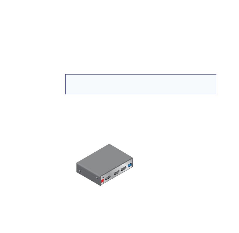
About the HDMI DA2
The Extron HDMI DA2 distribution amplifier distributes one HDMI input signal to two outputs simultaneously. It is fully High-bandwidth Digital Content Protection (HDCP) compliant.
The HDMI DA2 supports data rates up to 6.75 Gbps (2.25 Gbps per color) with up to 12-bit deep color and uses the EDID Minder® feature for EDID management.
The automatic output compatibility correction feature scans each output device to ensure that the output signal is compatible with the audio capabilities, color depth, and format requirements of the device. Each output is adjusted independently.
HDMI DA2 Features
HDMI signal distribution — The HDMI DA2 accepts one HDMI input and provides two HDMI outputs.
Key Minder® — Key Minder authenticates and maintains continuous HDCP encryption between the input and output devices to enable simultaneous distribution of a single encrypted source to two displays.
Signal Status LEDs — Front panel signal status LEDs indicate TMDS and HDCP status for the input and each output.
EDID Minder — This feature allows the user to choose from a list of 46 factory loaded EDID files, to import EDID information from either of the display devices, or to import and save an EDID file from a PC. EDID Minder has two modes of operation that can be selected and configured using SIS commands:
zz Automatic: EDID from the display connected to output 1 is read and stored at the input automatically (default mode). Use SIS commands to read and store EDID from output 2.
zz User assigned: EDID can be manually assigned from the internal factory EDID table, which contains 46 unique EDID files categorized by native resolution and audio support. Additionally, there are four user slots available to store and recall EDID from connected displays.
HDMI DA2 • Introduction |
1 |
Output Compatibility Correction — The HDMI DA2 monitors the EDID of each connected display to ensure it is compatible with the current input signal. The following adjustments are made for each output independently:
zz Interface format: If the connected display is DVI and the input signal is HDMI, the signal is reformatted to DVI. If the output is HDMI and the input is DVI, no reformatting is needed because HDMI is backwards compatible with DVI.
zz Video color bit depth: If the connected output device does not support the color bit depth of the input signal, it is truncated down to the next level that is supported
(12 bit > 10-bit > 8-bit). The signal can be forced to always truncate to 8-bit via Simple
Instruction Set (SIS™) commands, disabling deep color.
zz Audio: If the connected output device does not support the audio format of the input signal, audio is muted.
NOTE: These adjustments do not affect the actual video or audio data (there is no video scaling or audio decoding or mixing). It is up to the user or installer to ensure that the connected display device is compatible with the video resolution of the input signal.
Easy mounting options — The HDMI DA2 is a quarter rack wide, 1 inch high, and 3 inches deep, which allows the unit to be conveniently mounted in a rack or under furniture.
HDMI DA2 Application Diagram
TouchLink™
Control
System
TCP/IP
Extron
HDMI DA2
Distribution
Ampli er
TE
REMO
Tx
S
OUTPUT
POWERX |
|
12V |
MA |
0.4A |
INPUT |
|
|
HDMI Cables
 RS-232
HD Display
HD Display
Blu-ray Disc Player
Figure 1. HDMI DA2 Application Diagram
HDMI DA2 • Introduction |
2 |
Installation
This section of the guide describes the following topics concerned with the installation and setup of the HDMI DA2 distribution amplifier.
zz Installation Overview
zz Rear Panel Features
zz Connecting the Power Supply
zz Connecting the Input Source
zz Connecting Output Displays zz Wiring for RS-232 Control zz Connecting to the USB Port
Installation Overview
To install and set up the HDMI DA2, follow these instructions:
1.Mount the HDMI DA2 in a suitable location (see page 27).
2.Connect the provided 12 VDC power supply to the power connector. Be sure to read all attention points, notes, and warnings in this section before powering up the HDMI DA2
(see page 4).
3.Connect the display devices to the HDMI DA2 and power them on (see page 5).
The distribution amplifier automatically reads and stores EDID from the display connected to output 1.
4.If necessary, connect a control PC to the rear panel captive screw connector (see page 6) or the front panel USB port (see page 7).
5.Configure the HDMI DA2, using SIS commands (see page 17).
6.Connect and power on the input device (see page 5).
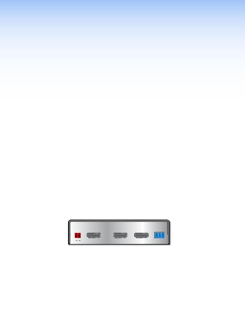
Rear Panel Features
POWER |
|
|
REMOTE |
||
12V |
|
|
|
||
0.4A MAX |
|
|
|
||
|
|
|
|
|
|
|
|
|
|
|
|
|
|
INPUT |
|
OUTPUTS |
|
|
a b |
c |
|
d |
|
Figure 2. HDMI DA2 Rear Panel
A B C D
Power supply connector
HDMI input connector
HDMI output connectors
RS-232 connectors
HDMI DA2 • Installation |
3 |
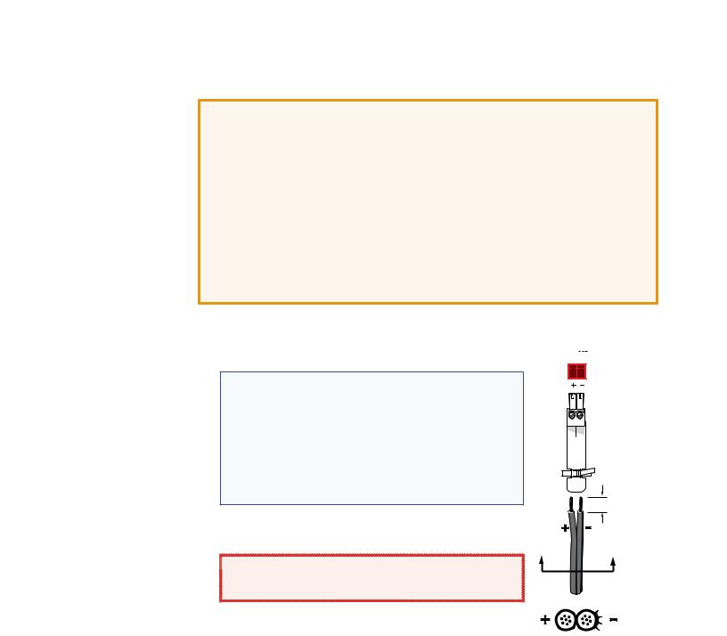
Connecting the Power Supply
Connect the provided 12 VDC, 1 A power supply to the HDMI DA2 by following these instructions:
ATTENTION: • This product is intended to be supplied by a Listed Power Unit marked “Class 2” or “LPS,” rated 12 VDC, maximum 1.0 A. Always use a power supply supplied or specified by Extron. Use of an unauthorized power supply voids all regulatory compliance certification and may cause damage to the supply and the end product.
•Unless otherwise stated, the AC/DC adapters are not suitable for use in air handling spaces or in wall cavities. The power supply is to be located within the same vicinity as the Extron AV processing equipment in an ordinary location, Pollution Degree 2, secured to the equipment rack within the dedicated closet, podium, or desk.
•The installation must always be in accordance with the applicable provisions of National Electrical Code ANSI/NFPA 70, article 75, and the Canadian Electrical Code part 1, section 16. The power supply shall not be permanently fixed to building structure or similar structure.
1.Cut the DC output cord to the length needed.
2.Strip the jacket to expose 3/16 inch (5 mm) of the conductor wire.
NOTES: • The length of the exposed wires in the stripping process is critical. The ideal length is 3/16 inches (5 mm). If the exposed section is longer, the exposed wires may touch, causing a short circuit between them. If it is shorter, the wires can be easily pulled out, even if tightly fastened by the captive screws.
• Do not tin the wires. Tinned wire does not hold its shape and can become loose over time.
3.Strip the jacket to expose 3/16 inch (5 mm) of the conductor wire.
 WARNING: Remove power before wiring. The two
power cord wires must be kept separate while the power supply is plugged in.
POWER 12V
0.4A MAX
|
3/16" |
|
(5 mm) Max. |
A |
A |
4.Verify the polarity of the wires.
5.Slide the exposed end into the captive screw connector and secure by tightening the screw.
Smooth Ridges
SECTION A–A
6. Use the supplied tie wrap to strap the power cord to the extended tail of the connector.
HDMI DA2 • Installation |
4 |
Connecting the Input Source
Use a HDMI cable to connect the input source to the female HDMI socket on the rear panel (B in figure 2).
The connectors are fully HDCP compliant. With cables up to 25 feet (7.6 m) they support resolutions of up to 1080p @ 60 Hz with 12-bit color. With cables up to 50 feet (15.2 m) they support 1080p or 1920x1200 @ 60 Hz with 8-bit color.
Follow these instructions to secure the input and output
HDMI connectors to the HDMI DA2 with the LockIt™ HDMI lacing bracket provided:
1. |
Plug the HDMI cable into the panel connection. |
1 |
2 |
|
|
||
2. |
Loosen the HDMI connection mounting screw from |
|
|
|
the panel enough to allow the LockIt lacing bracket |
|
|
|
to be placed over it. The screw does not have to be |
|
|
|
removed. |
3 |
|
3. Place the LockIt lacing bracket on the screw and against the HDMI connector, then tighten the screw to secure the bracket.
ATTENTION: Do not overtighten the HDMI connection mounting screw. The 4 shield it fastens to is very thin
and can easily be stripped.
4. Loosely place the included tie wrap around the HDMI connector and the LockIt lacing bracket as shown.
5.While holding the connector securely against the lacing bracket, tighten the tie wrap, then remove any excess length.
Connecting the Output Displays
Use a HDMI cable to connect up to two output displays to the female HDMI sockets on the rear panel (C in figure 2 on page 3).
NOTE: Secure the input and output HDMI connectors to the HDMI DA2 with the provided
LockIt™ HDMI lacing bracket (see Connecting the Input Source).
Connect the primary display to output 1 since EDID from output 1 is read and stored automatically. If necessary, EDID can be configured using SIS commands (see page 17).
The HDMI DA2 monitors the EDID of each connected display to ensure it is compatible with the current input signal. The following adjustments are made for each output independently:
zz Interface format: If the connected display is DVI and the input signal is HDMI, the signal is reformatted to DVI. If the output is HDMI and the input is DVI, no reformatting is needed because HDMI is backwards compatible with DVI.
zz Video color bit depth: If the connected output device does not support the color bit depth of the input signal, it is truncated down to the next level that is supported
(12 bit > 10-bit > 8-bit). The signal can be forced to always truncate to 8-bit via SIS commands, disabling deep color.
zz Audio: If the connected output device does not support the audio format of the input signal, audio is muted.
If the source requires HDCP encryption and the display is not HDCP compliant, that output channel outputs a green screen.
Both outputs carry +5 VDC and up to 250 mA on pin 18, regulated by a current limiting circuit.
HDMI DA2 • Installation |
5 |
Loading...