


 Loading...
ExtremeSwitching and
Summit Switches: Hardware
Installation Guide
for Switches Using ExtremeXOS 21 or Later
121137-04
Published August 2017
Copyright © 2017 Extreme Networks, Inc. All rights reserved.
Legal Notice
Extreme Networks, Inc. reserves the right to make changes in specifications and other information contained in this document and its website without prior notice. The reader should in all cases consult representatives of Extreme Networks to determine whether any such changes have been made.
The hardware, firmware, software or any specifications described or referred to in this document are subject to change without notice.
Trademarks
Extreme Networks and the Extreme Networks logo are trademarks or registered trademarks of Extreme Networks, Inc. in the United States and/or other countries.
All other names (including any product names) mentioned in this document are the property of their respective owners and may be trademarks or registered trademarks of their respective companies/owners.
For additional information on Extreme Networks trademarks, please see: www.extremenetworks.com/company/legal/trademarks
Software Licensing
Some software files have been licensed under certain open source or third-party licenses. Enduser license agreements and open source declarations can be found at: www.extremenetworks.com/support/policies/software-licensing
Support
For product support, phone the Global Technical Assistance Center (GTAC) at 1-800-998-2408 (toll-free in U.S. and Canada) or +1-408-579-2826. For the support phone number in other countries, visit: http://www.extremenetworks.com/support/contact/
For product documentation online, visit: https://www.extremenetworks.com/documentation/

Table of Contents |
|
Preface......................................................................................................................................... |
6 |
Audience................................................................................................................................................................................... |
6 |
Conventions............................................................................................................................................................................. |
6 |
Providing Feedback to Us................................................................................................................................................. |
7 |
Getting Help............................................................................................................................................................................. |
8 |
Related Publications............................................................................................................................................................ |
8 |
Chapter 1: ExtremeSwitching and Summit Switches............................................................ |
9 |
Overview of the Switches............................................................................................................................................... |
10 |
ExtremeSwitching X440-G2 Series Switches......................................................................................................... |
11 |
Summit X450-G2 Series Switches............................................................................................................................. |
27 |
ExtremeSwitching and Summit X460-G2 Series Switches........................................................................... |
38 |
ExtremeSwitching X620 Series Switches.............................................................................................................. |
54 |
Summit X670-G2 Series Switches.............................................................................................................................. |
61 |
ExtremeSwitching X690 Series Switches.............................................................................................................. |
65 |
Summit X770 Series Switches...................................................................................................................................... |
72 |
ExtremeSwitching X870 Series Switches............................................................................................................... |
76 |
Pluggable Interfaces for ExtremeSwitching and Summit Switches........................................................... |
81 |
Chapter 2: Power supplies...................................................................................................... |
83 |
External Power Supplies................................................................................................................................................. |
83 |
Replaceable Internal Power Supplies....................................................................................................................... |
93 |
Chapter 3: Option Cards and Versatile Interface Modules................................................ |
99 |
Optional Ports for the X460-G2 Series Switches............................................................................................... |
99 |
Chapter 4: Site Preparation.................................................................................................. |
104 |
Planning Your Site............................................................................................................................................................ |
104 |
Operating Environment Requirements.................................................................................................................. |
105 |
Rack Specifications and Recommendations....................................................................................................... |
108 |
Evaluating and Meeting Cable Requirements...................................................................................................... |
110 |
Meeting Power Requirements...................................................................................................................................... |
116 |
Following Applicable Industry Standards.............................................................................................................. |
119 |
Chapter 5: Building Stacks.................................................................................................... |
120 |
Introduction to Stacking............................................................................................................................................... |
120 |
Planning to Create Your Stack.................................................................................................................................... |
132 |
Setting up the Physical Stack..................................................................................................................................... |
150 |
Chapter 6: Installing ExtremeSwitching and Summit Switches...................................... |
159 |
Safety Considerations for Installing Switches.................................................................................................... |
160 |
Pre-installation Requirements.................................................................................................................................... |
160 |
Attaching the Switch to a Rack or Cabinet........................................................................................................... |
161 |
Installing Optional Components................................................................................................................................ |
165 |
Installing Internal Power Supplies............................................................................................................................. |
165 |
Connecting Power to the Switch................................................................................................................................ |
191 |
Connecting Network Interface Cables..................................................................................................................... |
191 |
Performing Initial Management Tasks..................................................................................................................... |
192 |
Chapter 7: Installing Summit External Power Supplies.................................................... |
196 |
ExtremeSwitching and Summit Switches: Hardware Installation Guide |
3 |

Table of Contents
Safety Considerations for Installing Power Supplies....................................................................................... |
196 |
Pre-installation Requirements..................................................................................................................................... |
197 |
Installing an EPS-C2 Power Supply.......................................................................................................................... |
197 |
Installing an STK-RPS-150PS Redundant Power Supply.............................................................................. |
205 |
Installing an RPS-150XT Redundant Power Supply......................................................................................... |
210 |
Installing an RPS-500p Redundant Power Supply........................................................................................... |
214 |
Installing an STK-RPS-1005PS Redundant Power Supply............................................................................ |
217 |
Chapter 8: Installing Port Option Cards and VIMs............................................................ |
222 |
Installing a Versatile Interface Module or Clock Module in a Summit X460-G2 Series Switch..222 |
|
Chapter 9: Replacing AC Power Supplies.......................................................................... |
224 |
Replacing a Summit 300 W AC Power Supply................................................................................................. |
224 |
Replacing a Summit 350 W or 715 W AC Power Supply............................................................................. |
226 |
Replacing a Summit 550 W AC Power Supply................................................................................................. |
228 |
Replacing a Summit 750 W AC Power Supply................................................................................................. |
230 |
Replacing a Summit 770 W AC Power Supply................................................................................................. |
234 |
Replacing a Summit 1100 W AC Power Supply................................................................................................ |
236 |
Removing an STK-RPS-150PS Redundant Power Supply............................................................................ |
238 |
Removing an RPS-150XT Redundant Power Supply...................................................................................... |
238 |
Removing an RPS-500p Redundant Power Supply....................................................................................... |
238 |
Removing an STK-RPS-1005PS Redundant Power Supply........................................................................ |
239 |
Chapter 10: Replacing DC Power Supplies........................................................................ |
240 |
Replacing a Summit 300 W DC Power Supply................................................................................................ |
240 |
Replacing a Summit 550 W DC Power Supply................................................................................................. |
247 |
Replacing a Summit 1100 W DC Power Supply................................................................................................ |
253 |
Chapter 11: Replacing Fan Modules..................................................................................... |
259 |
Pre-Installation Requirements................................................................................................................................... |
259 |
Airflow Direction Requirements............................................................................................................................... |
259 |
Replacing a Fan Module............................................................................................................................................... |
259 |
Chapter 12: Replacing Port Option Cards and VIMs......................................................... |
261 |
Replacing a Versatile Interface Module or Clock Module in a Summit X460-G2 Series |
|
Switch..................................................................................................................................................................................... |
261 |
Chapter 13: Removing ExtremeSwitching and Summit Switches................................... |
263 |
Removing an AC Power Supply................................................................................................................................ |
263 |
Removing a DC Power Supply.................................................................................................................................. |
264 |
Removing a Switch from a Rack.............................................................................................................................. |
265 |
Appendix A: Safety Information.......................................................................................... |
267 |
Considerations Before Installing............................................................................................................................... |
267 |
General Safety Precautions......................................................................................................................................... |
268 |
Maintenance Safety........................................................................................................................................................ |
269 |
Cable Routing for LAN Systems............................................................................................................................... |
269 |
Installing Power Supply Units and Connecting Power.................................................................................. |
270 |
Selecting Power Supply Cords................................................................................................................................... |
271 |
Battery Replacement and Disposal......................................................................................................................... |
272 |
Battery Warning - Taiwan............................................................................................................................................. |
272 |
Fiber Optic Ports and Optical Safety..................................................................................................................... |
272 |
Sicherheitshinweise......................................................................................................................................................... |
273 |
ExtremeSwitching and Summit Switches: Hardware Installation Guide |
4 |

Table of Contents
Überlegungen vor der Installation........................................................................................................................... |
274 |
Allgemeine Sicherheitshinweise............................................................................................................................... |
274 |
Sicherheit bei Wartungsarbeiten.............................................................................................................................. |
275 |
Kabelverlegung für LAN-Systeme........................................................................................................................... |
275 |
Installation der Netzteile und Netzanschluss..................................................................................................... |
276 |
Auswahl der Netzkabel................................................................................................................................................. |
278 |
Wechseln und Entsorgen der Batterie.................................................................................................................. |
278 |
LWL-Ports und optische Sicherheit........................................................................................................................ |
278 |
Konformität von GBIC, SFP (Mini-GBIC), QSFP+, XENPAK und XFP.................................................... |
279 |
Mögliche Netzanschlussgerätund Lüftereinsatz-Konfigurationen für X770-32q......................... |
280 |
Appendix B: Technical Specifications................................................................................. |
282 |
ExtremeSwitching X440-G2 Series Switches Technical Specifications................................................ |
282 |
Summit X450-G2 Series Switches Technical Specifications...................................................................... |
288 |
ExtremeSwitching and Summit X460-G2 Series Switches Technical Specifications.................... |
294 |
ExtremeSwitching X620 Series Switches Technical Specifications....................................................... |
303 |
Summit X670-G2 Series Switches Technical Specifications...................................................................... |
309 |
ExtremeSwitching X690 Series Switches Technical Specifications......................................................... |
313 |
Summit X770 Series Switches Technical Specifications................................................................................ |
317 |
ExtremeSwitching X870 Series Switches Technical Specifications......................................................... |
321 |
Summit 300 W Power Supplies Technical Specifications........................................................................... |
324 |
Summit 350 W Power Supplies Technical Specifications............................................................................ |
326 |
Summit 550 W Power Supplies Technical Specifications............................................................................ |
327 |
Summit 715 W Power Supplies Technical Specifications.............................................................................. |
328 |
Summit 750 W Power Supplies Technical Specifications............................................................................ |
329 |
Summit 770 W Power Supplies Technical Specifications............................................................................ |
330 |
Summit 1100 W Power Supplies Technical Specifications............................................................................ |
331 |
EPS-C2 Redundant Power Supply Technical Specifications...................................................................... |
333 |
RPS-90 Redundant Power Supply Technical Specifications...................................................................... |
333 |
STK-RPS-150PS and RPS Shelves Technical Specifications....................................................................... |
334 |
RPS-150XT Redundant Power Supply Technical Specifications............................................................... |
335 |
RPS-500p Redundant Power Supply Technical Specifications................................................................ |
337 |
STK-RPS-1005PS Redundant Power Supply Technical Specifications.................................................. |
339 |
Power Cord Requirements for AC-Powered Switches and AC Power Supplies.............................. |
340 |
Console Connector Pinouts......................................................................................................................................... |
341 |
Taiwan Warnings.............................................................................................................................................................. |
343 |
Japan (VCCI Class A)..................................................................................................................................................... |
343 |
Korea EMC Statement................................................................................................................................................... |
344 |
Glossary......................................................................................................................................... |
345 |
Index........................................................................................................................................ |
359 |
ExtremeSwitching and Summit Switches: Hardware Installation Guide |
5 |

Preface
This guide provides the instructions and supporting information needed to install the following Extreme Networks® ExtremeSwitching® andSummit® family switches:
•
•
•
•
•
•
•
•
ExtremeSwitching X440-G2 Series Switches on page 11 Summit X450-G2 Series Switches on page 27
ExtremeSwitching and Summit X460-G2 Series Switches on page 38 ExtremeSwitching X620 Series Switches on page 54
Summit X670-G2 Series Switches on page 61 ExtremeSwitching X690 Series Switches on page 65 Summit X770 Series Switches on page 72 ExtremeSwitching X870 Series Switches on page 76
The guide includes information about site preparation, switch functionality, and switch operation.
Audience
This guide is intended for use by network administrators responsible for installing and setting up network equipment. It assumes a basic working knowledge of:
•
•
•
•
•
•
Local area networks (LANs) Ethernet concepts
Ethernet switching and bridging concepts Routing concepts
SNMP (Simple Network Management Protocol)
Basic equipment installation procedures
See the ExtremeXOS 22.3 User Guide and the ExtremeXOS 22.3 Command Reference Guide for information about configuring ExtremeSwitching and Summit switches.
Note
If the information in an installation note or release note shipped with your Extreme Networks equipment differs from the information in this guide, follow the installation or release note.
Conventions
This section discusses the conventions used in this guide.
Text Conventions
The following tables list text conventions that are used throughout this guide.
ExtremeSwitching and Summit Switches: Hardware Installation Guide |
6 |

Preface
Table 1: Notice Icons
Icon |
Notice Type |
Alerts you to... |
|
|
|
|
General Notice |
Helpful tips and notices for using the product. |
|
|
|
|
Note |
Important features or instructions. |
|
|
|
|
Caution |
Risk of personal injury, system damage, or loss of data. |
|
|
|
|
Warning |
Risk of severe personal injury. |
|
|
|
|
New |
This command or section is new for this release. |
|
|
|
Table 2: Text Conventions
Convention |
Description |
|
|
Screen displays |
This typeface indicates command syntax, or represents information as it appears on the |
|
screen. |
|
|
The words enter and |
When you see the word “enter” in this guide, you must type something, and then press |
type |
the Return or Enter key. Do not press the Return or Enter key when an instruction |
|
simply says “type.” |
|
|
[Key] names |
Key names are written with brackets, such as [Return] or [Esc]. If you must press two |
|
or more keys simultaneously, the key names are linked with a plus sign (+). Example: |
|
Press [Ctrl]+[Alt]+[Del] |
|
|
Words in italicized type |
Italics emphasize a point or denote new terms at the place where they are defined in |
|
the text. Italics are also used when referring to publication titles. |
|
|
Terminology
When features, functionality, or operation is specific to a switch family, such as ExtremeSwitching™ or Summit®, the family name is used. Explanations about features and operations that are the same across all product families simply refer to the product as the switch.
Providing Feedback to Us
We are always striving to improve our documentation and help you work better, so we want to hear from you! We welcome all feedback but especially want to know about:
•Content errors or confusing or conflicting information.
•Ideas for improvements to our documentation so you can find the information you need faster.
•Broken links or usability issues.
ExtremeSwitching and Summit Switches: Hardware Installation Guide |
7 |

Preface
If you would like to provide feedback to the Extreme Networks Information Development team about this document, please contact us using our short online feedback form. You can also email us directly at internalinfodev@extremenetworks.com.
Getting Help
If you require assistance, contact Extreme Networks using one of the following methods:
•GTAC (Global Technical Assistance Center) for Immediate Support
•Phone: 1-800-998-2408 (toll-free in U.S. and Canada) or +1 408-579-2826. For the support phone number in your country, visit: www.extremenetworks.com/support/contact
•Email: support@extremenetworks.com. To expedite your message, enter the product name or model number in the subject line.
•GTAC Knowledge — Get on-demand and tested resolutions from the GTAC Knowledgebase, or create a help case if you need more guidance.
•The Hub — A forum for Extreme customers to connect with one another, get questions answered, share ideas and feedback, and get problems solved. This community is monitored by Extreme Networks employees, but is not intended to replace specific guidance from GTAC.
•Support Portal — Manage cases, downloads, service contracts, product licensing, and training and certifications.
Before contacting Extreme Networks for technical support, have the following information ready:
•Your Extreme Networks service contract number and/or serial numbers for all involved Extreme Networks products
•A description of the failure
•A description of any action(s) already taken to resolve the problem
•A description of your network environment (such as layout, cable type, other relevant environmental information)
•Network load at the time of trouble (if known)
•The device history (for example, if you have returned the device before, or if this is a recurring problem)
•Any related RMA (Return Material Authorization) numbers
Related Publications
ExtremeSwitching X8, ExtremeSwitching, and E4G Hardware
Documentation
•Extreme Hardware/Software Compatibility and Recommendation Matrices
•Extreme Networks Pluggable Transceivers Installation Guide
•ExtremeXOS 22.3 User Guide
•ExtremeXOS 22.3 Command Reference Guide
•ExtremeSwitching and Summit Switches: Hardware Installation Guide for Switches Using ExtremeXOS 16 or Earlier
•Environmental Guidelines for ExtremeSwitching Products
ExtremeSwitching and Summit Switches: Hardware Installation Guide |
8 |

1 ExtremeSwitching and Summit
Switches
Overview of the Switches
ExtremeSwitching X440-G2 Series Switches
Summit X450-G2 Series Switches
ExtremeSwitching and Summit X460-G2 Series Switches
ExtremeSwitching X620 Series Switches
Summit X670-G2 Series Switches
ExtremeSwitching X690 Series Switches
Summit X770 Series Switches
ExtremeSwitching X870 Series Switches
Pluggable Interfaces for ExtremeSwitching and Summit Switches
The ExtremeSwitching and Summit switches are compact enclosures 1.75 inches high (1 U). Each switch model provides between 8 and 72 high-density copper or fiber optic ports operating at speeds up to 40 Gbps. Many models also provide combination copper/fiber uplink ports. PoE (Power over Ethernet) connections and options for adding 10-Gbps or 40-Gbps uplink connections are available on some models.
Many ExtremeSwitching and Summit switches include high-speed stacking interfaces that allow you to connect up to eight switches into a single SummitStack management entity. Models are available for AC or DC power connection; all switches make provision for redundant power supplies. Most models have connections for optional external redundant power supplies: the X450-G2 (PoE models), X460-G2, X620 (16-port models), X670-G2, and X770 switches provide two bays for pluggable power supplies.
This document describes switches that are supported on ExtremeXOS version 21.1 or later versions. For information about other Summit switches, refer to the ExtremeSwitching and Summit Switches: Hardware Installation Guide for Switches Using ExtremeXOS 16 or Earlier.
The following sections contain general information about the switches:
•
•
•
•
•
•
•
•
ExtremeSwitching X440-G2 Series Switches on page 11 Summit X450-G2 Series Switches on page 27
ExtremeSwitching and Summit X460-G2 Series Switches on page 38 ExtremeSwitching X620 Series Switches on page 54
Summit X670-G2 Series Switches on page 61 ExtremeSwitching X690 Series Switches on page 65 Summit X770 Series Switches on page 72 ExtremeSwitching X870 Series Switches on page 76
ExtremeSwitching and Summit Switches: Hardware Installation Guide |
9 |

ExtremeSwitching and Summit Switches
Overview of the Switches
The following sections describe the ExtremeSwitching and Summit switches and summarize the features available in each series.
Model numbers for the switches are in the following format:
<Series>-<number of front-panel I/O ports><port type><internal power supply type>
•The number of ports ranges from 8 to 72.
•The port type can be t (copper), p (copper providing PoE), q (QSFP+), or x (fiber).
•For models with integral power supplies, the power supply type can be AC (no designation) or DC.
Models with pluggable power supplies can accommodate either AC or DC supplies and have no power designation in their model numbers.
Note
See the ExtremeXOS 22.3 User Guide and the ExtremeXOS 22.3 Command Reference Guide for feature-specific information about the Summit switches and for information regarding switch configuration.
Combination Ports and Failover
ExtremeSwitching and Summit switches provide 2, 4, or 12 uplink ports implemented as combination ports that pair a copper port using RJ45 connectors with an optical port using LC connectors.
The copper port operates as an autonegotiating 10/100/1000BASE-T port. The optical port allows Gigabit Ethernet uplink connections through Extreme Networks small form factor pluggable (SFP) interface modules. See the individual switch descriptions for the port numbers of the combination ports on each switch model.
ExtremeSwitching and Summit switches support automatic failover from an active fiber port to a copper backup or from an active copper port to a fiber port. If one of the uplink connections fails, the Summit uplink connection automatically fails over to the second connection. To set up a redundant link on a combination port, connect the active 1000BASE-T and fiber links to both the RJ45 and SFP interfaces of that port.
Gigabit Ethernet uplink redundancy on the ExtremeSwitching and Summit switches follows these rules:
•With both the SFP and 1000BASE-T interfaces connected on a combination port, only one interface can be activated. The other is inactive.
•If only one interface is connected, the switch activates the connected interface.
•The switch determines whether the port uses the fiber or copper connection based on the order in which the connectors are inserted into the switch. When the switch senses that an SFP and a copper connector are inserted, the switch enables the uplink redundancy feature. For example, if you first connect copper ports x and y on a switch, and then insert SFPs into ports x and y, the switch assigns the copper ports as active ports and the fiber ports as redundant ports.
Hardware identifies when a link is lost and responds by swapping the primary and redundant ports to maintain stability. After a failover occurs, the switch keeps the current port assignment until another
ExtremeSwitching and Summit Switches: Hardware Installation Guide |
10 |
ExtremeSwitching and Summit Switches
failure occurs or a user changes the assignment using the CLI. For more information about configuring automatic failover on combination ports, see the ExtremeXOS 22.3 User Guide.
Port Partitioning
On some ExtremeSwitching and Summit switch models, you can configure QSFP28 and QSFP+ ports either as single ports or as multiple, partitioned ports. In a partitioned port, with appropriate cabling, the original physical port can accommodate multiple data lanes at lower bandwidths.
The following partitioning options are available:
Table 3: QSFP28 and QSFP+ Port Partitioning
Switch Model |
Port Bandwidth |
Each Physical Port Can Operate as.... |
|
|
|
X670-G2-48x-4q |
40 Gb |
One 40 Gb port or |
QSFP+ |
|
Four 10 Gb ports |
|
|
|
X770 (all models) |
40 Gb |
One 40 Gb port or |
QSFP+ |
|
Four 10 Gb ports |
|
|
|
X690 (all models) |
100 Gb |
One 100 Gb port or |
QSFP28 and QSFP+ |
|
Two 50 Gb ports or |
|
|
Four 25 Gb ports |
|
|
|
|
40 Gb |
One 40 Gb port or |
|
|
Four 10 Gb ports |
|
|
|
X870 (all models) |
100 Gb |
One 100 Gb port or |
QSFP28 and QSFP+ |
|
Two 50 Gb ports or |
|
|
Four 25 Gb ports |
|
|
Note: On X870-96x-8c series switches, an optional Switch |
|
|
Port Speed License is required to increase the data rate to |
|
|
100 Gb on physical ports 1 through 24. No license is required |
|
|
for 100 Gb capability on physical ports 25 through 32. |
|
|
|
|
40 Gb |
One 40 Gb port or |
|
|
Four 10 Gb ports |
|
|
|
For information about configuring partitioned ports, see the ExtremeXOS 22.3 Command Reference Guide.
ExtremeSwitching X440-G2 Series Switches
The ExtremeSwitching X440-G2 switches are cost-effective campus edge switches. They provide 12, 24, or 48 Ethernet ports that deliver high-density fast Ethernet or Gigabit Ethernet connectivity using fixed 10/100/1000BASE-T ports or 100/1000 BASE-X ports. In addition, some models offer IEEE 802.3at PoE + ports.
Note
An extended-temperature model, 24fx-GE4, provides 24 ports of 100Base-FX. Another extended-temperature model, 12t8fx-GE4, provides 12 ports of 10/100/1000BASE-T and eight ports of 100Base-FX.
ExtremeSwitching and Summit Switches: Hardware Installation Guide |
11 |

ExtremeSwitching and Summit Switches
The ExtremeSwitching X440-G2 series switches include the following base models:
•ExtremeSwitching X440-G2-12t-10GE4 switch
•ExtremeSwitching X440-G2-12p-10GE4 switch
•ExtremeSwitching X440-G2-24t-10GE4 switch
•ExtremeSwitching X440-G2-24x-10GE4 switch
•ExtremeSwitching X440-G2-24p-10GE4 switch
•ExtremeSwitching X440-G2-48t-10GE4 switch
•ExtremeSwitching X440-G2-48p-10GE4 switch
•ExtremeSwitching X440-G2-24t-10GE4-DC switch
•ExtremeSwitching X440-G2-48t-10GE4-DC switch
•ExtremeSwitching X440-G2-12t8fx-GE4 switch
•ExtremeSwitching X440-G2-24fx-GE4 switch
•ExtremeSwitching X440-G2-24t-GE4 switch
Most X440-G2 switches support both half-duplex and full-duplex communication over 10/100/1000BASE-T ports. For details, see the "Switch Ports and Slots" topics for the individual base models.
All models come equipped with four ports of SFP 1 GbE resident on either the faceplate or rear panel. On the 12-port, 24-port, and 48-port 10/100/1000 models, except for the extended-temperature models, these 1 GbE ports can be upgraded to 10 Gb SFP+ Ethernet through software licensing. The 24and 48-port 10/100/1000 models (except the X440-G2-24t-GE4) have four 1 GbE SFP combination ports on the front panel.
ExtremeSwitching X440-G2 series switches require ExtremeXOS version 21.1.1 or later.
Security
These switches provide comprehensive security management:
•User policy and host integrity enforcement, and identity management
•Universal Port Dynamic Security Profiles to provide fine granular security policies in the network
•Threat detection and response instrumentation to react to network intrusion with CLEAR-Flow Security Rules Engine
•Denial of Service (DoS) protection and IP security against man-in-the-middle and DoS attacks to harden the network infrastructure
Stacking
Up to eight X440-G2 switches can be stacked using SummitStack-V. Each X440-G2 unit (except the extended temperature range switches) comes equipped with two stacking ports using an SFP+ interface. Standard 10 Gb Ethernet Optics and passive and active cables can be used in the SFP+ ports for stacking X440-G2s together using SummitStack-V.
ExtremeXOS supports the SummitStack-V capability using two SFP+ ports as stacking ports, enabling the use of standard cabling and optics technologies used for 10 GbE SFP+. SummitStack-V provides long-distance stacking connectivity of up to 40 km while reducing the cable complexity of
ExtremeSwitching and Summit Switches: Hardware Installation Guide |
12 |

ExtremeSwitching and Summit Switches
implementing a stacking solution. For a list of X440-G2 ports that can be used with SummitStack-V, see ExtremeSwitching X440-G2 Stacking on page 134.
On X440-G2 switches, SummitStack-V is compatible with X450-G2 and X460-G2 switches with 10 Gb uplinks and with X620, X670-G2, and X770 switches running the same version of ExtremeXOS. SummitStack-V enabled 10 GbE ports must be physically direct-connected.
Note
The SFP+ stacking ports on the base X440-G2 switches are 1 Gb Ethernet ports, not 10 Gb Ethernet ports. The switches run a 10 Gb stacking protocol by default, but they do not run the 10 Gb Ethernet protocol without licensed entitlement. Twoand four-port licenses are available to enable the ports to run the 10 Gb Ethernet protocol.
Note
SummitStack-V is not supported on the following extended temperature range switch models:
• X440-G2-12t8fx-GE4
•X440-G2-24fx-GE4
•X440-G2-24t-GE4
Operating Temperatures
Most X440-G2 switch models support an operating range from 0°C to 50°C. The following models extend the operating range from 0°C to 60°C:
•
•
•
X440-G2-12t8fx-GE4
X440-G2-24fx-GE4
X440-G2-24t-GE4
Additional Features
For all models, a serial console port on the front panel allows you to connect a terminal and perform local management. An Ethernet management port can be used to connect the system to a parallel management network for administration. Alternatively, you can use an Ethernet cable to connect this port directly to a laptop to view and locally manage the switch configurations.
The rear panel provides an AC power input socket or DC input connector, along with a redundant power connector. The switch automatically adjusts to the supply voltage. The redundant power connector allows you to connect the switch to either a standalone external redundant power supply or the EPS-C2 external power system. When a compatible external power supply is used with the ExtremeSwitching X440-G2 switch, the internal and external power supplies are fully fault tolerant. If one power supply fails, the other power supply will provide suŠcient power to operate the switch.
All X440-G2 switches support external redundant power options. For details, refer to Table 26 on page 83.
ExtremeSwitching and Summit Switches: Hardware Installation Guide |
13 |
ExtremeSwitching and Summit Switches
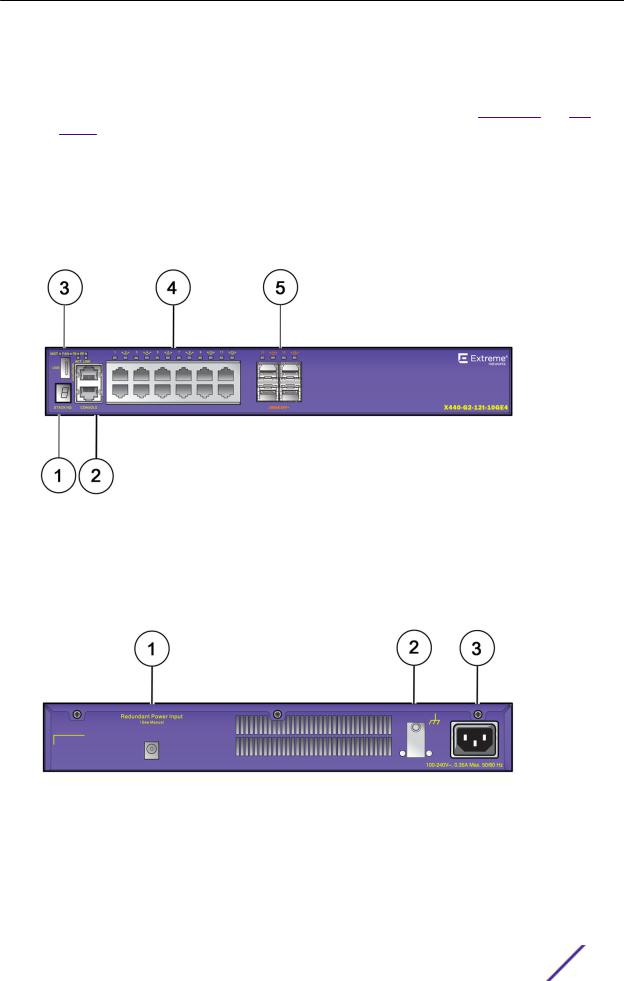
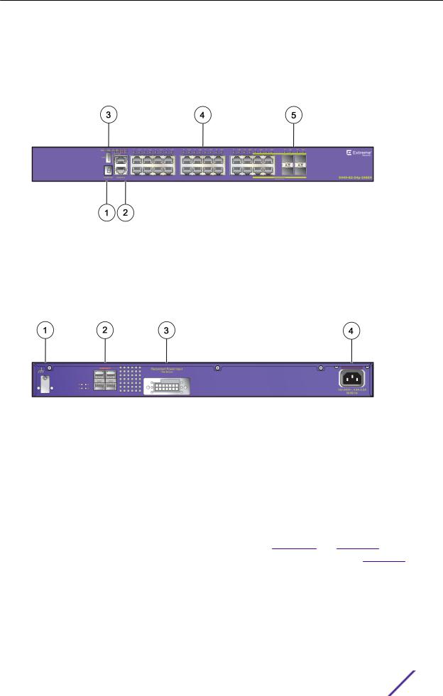
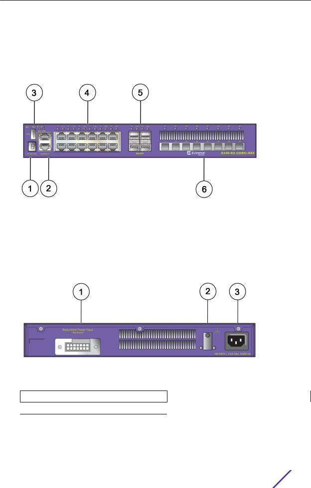
ExtremeSwitching X440-G2-12t-10GE4 Switch Ports and Slots
The ExtremeSwitching X440-G2-12t-10GE4 switch ports and slots include:
•12 front panel 10/100/1000BASE-T ports (RJ45), all of which support both half-duplex and fullduplex communication.
•Four unpopulated 1GBASE-X SFP ports that can be upgraded to 10Gb Ethernet.
•Ethernet management port (10/100/1000BASE-T).
•Serial console port implemented as an RJ45 connector used to connect a terminal and perform local management.
•One front panel USB 2.0 port, operational on switches running ExtremeXOS version 22.2 or later.
•One rear redundant power supply connector (coaxial barrel connector).
Figure 1: ExtremeSwitching X440-G2-12t-10GE4 Front Panel
1 = Stack number indicator |
4 = 10/100/1000BASE-T copper ports |
|
|
2 = Console port/Ethernet management port |
5 = SFP+ Ports upgradeable to 10GBASE-X |
|
|
3 = USB port (active with ExtremeXOS version 22.2 or later) |
|
|
|
Figure 2: ExtremeSwitching X440-G2-12t-10GE4 Rear Panel
1 = Redundant power input |
3 = AC power input socket |
|
|
2 = Grounding lug |
|
|
|
ExtremeSwitching and Summit Switches: Hardware Installation Guide |
14 |
ExtremeSwitching and Summit Switches
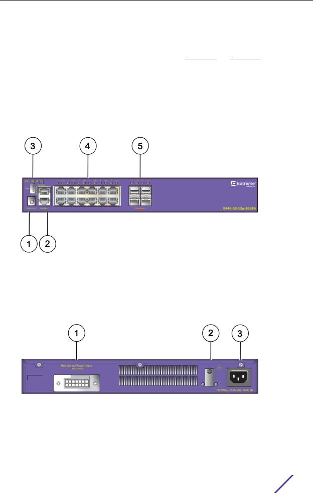
ExtremeSwitching X440-G2-12p-10GE4 Switch Ports and Slots
The ExtremeSwitching X440-G2-12p-10GE4 switch ports and slots include:
•12 front panel PoE+ ports of 10/100/1000BASE-T. Both half-duplex and full-duplex communication are supported on all 12 ports.
•Four unpopulated 1GBASE-X SFP ports that can be upgraded to 10Gb Ethernet.
•Ethernet management port (10/100/1000BASE-T).
•Serial console port implemented as an RJ45 connector used to connect a terminal and perform local management.
•One front panel USB 2.0 port, operational on switches running ExtremeXOS version 22.2 or later.
•One rear redundant power supply connector.
Figure 3: ExtremeSwitching X440-G2-12p-10GE4 Front Panel
1 = Stack number indicator |
4 = 10/100/1000BASE-T copper ports |
|
|
2 = Console port/Ethernet management port |
5 = SFP+ Ports upgradeable to 10GBASE-X |
|
|
3 = USB port (active with ExtremeXOS version 22.2 or later) |
|
|
|
Figure 4: ExtremeSwitching X440-G2-12p-10GE4 Rear Panel
1 = Redundant power input |
3 = AC power input socket |
|
|
2 = Grounding lug |
|
|
|
ExtremeSwitching and Summit Switches: Hardware Installation Guide |
15 |
ExtremeSwitching and Summit Switches
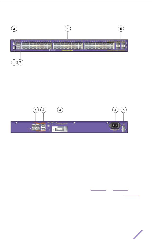
ExtremeSwitching X440-G2-24t-10GE4 Switch Ports and Slots
The ExtremeSwitching X440-G2-24t-10GE4 switch ports and slots include:
•24 front panel ports of 10/100/1000BASE-T (RJ45). Both half-duplex and full-duplex communication are supported on ports 1 through 16. Ports 17 through 24 are full-duplex only.
•Four unpopulated front panel 1GBASE-X SFP combination ports.
•Four unpopulated rear panel 1GBASE-X SFP ports that can be upgraded to 10Gb Ethernet.
•Ethernet management port (10/100/1000BASE-T).
•Serial console port implemented as an RJ45 connector used to connect a terminal and perform local management.
•One front panel USB 2.0 port, operational on switches running ExtremeXOS version 22.2 or later.
•One rear redundant power supply connector.
Figure 5: ExtremeSwitching X440-G2-24t-10GE4 Front Panel
1 = Stack number indicator |
4 = 10/100/1000BASE-T copper ports |
|
|
|
|
2 |
= Console port/Ethernet management port |
5 = 1000BASE-X SFP combination ports |
|
|
|
3 |
= USB port (active with ExtremeXOS version 22.2 or later) |
|
|
|
|
Figure 6: ExtremeSwitching X440-G2-24t-10GE4 Rear Panel
1 = Grounding lug |
3 = Redundant power input |
|
|
2 = SFP+ Ports upgradeable to 10GBASE-X |
4 = AC power input socket |
|
|
ExtremeSwitching X440-G2-24x-10GE4 Switch Ports and Slots
The ExtremeSwitching X440-G2-24x-10GE4 switch ports and slots include:
ExtremeSwitching and Summit Switches: Hardware Installation Guide |
16 |
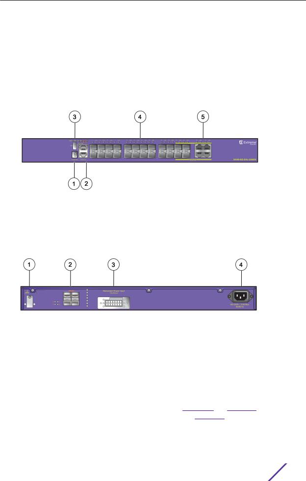
ExtremeSwitching and Summit Switches
•24 front panel 1GBASE-X SFP ports.
•Four unpopulated front panel 10/100/1000BASE-T (RJ45) ports.
•Four unpopulated rear panel 1GBASE-X SFP ports that can be upgraded to 10Gb Ethernet.
•Ethernet management port (10/100/1000BASE-T).
•Serial console port implemented as an RJ45 connector used to connect a terminal and perform local management.
•One front panel USB 2.0 port, operational on switches running ExtremeXOS version 22.2 or later.
•One rear redundant power supply connector.
Figure 7: ExtremeSwitching X440-G2-24x-10GE4 Front Panel
1 = Stack number indicator |
4 = 1GBASE-X SFP ports |
|
|
2 = Console port/Ethernet management port |
5 = 10/100/1000BASE-T combination ports |
|
|
3 = USB port (active with ExtremeXOS version 22.2 or later) |
|
|
|
Figure 8: ExtremeSwitching X440-G2-24x-10GE4 Rear Panel
1 = Grounding lug |
3 = Redundant power input |
|
|
2 = SFP+ Ports upgradeable to 10GBASE-X |
4 = AC power input socket |
|
|
ExtremeSwitching X440-G2-24p-10GE4 Switch Ports and Slots
The ExtremeSwitching X440-G2-24p-10GE4 switch ports and slots include:
•24 front panel PoE+ ports of 10/100/1000BASE-T. Both half-duplex and full-duplex communication are supported on ports 1 through 16. Ports 17 through 24 are full-duplex only.
•Four unpopulated front panel 1GBASE-X SFP combination ports.
•Four unpopulated rear panel 1GBASE-X SFP ports that can be upgraded to 10Gb Ethernet.
•Ethernet management port (10/100/1000BASE-T).
ExtremeSwitching and Summit Switches: Hardware Installation Guide |
17 |
ExtremeSwitching and Summit Switches
•Serial console port implemented as an RJ45 connector used to connect a terminal and perform local management.
•One front panel USB 2.0 port, operational on switches running ExtremeXOS version 22.2 or later.
•One rear redundant power supply connector.
Figure 9: ExtremeSwitching X440-G2-24p-10GE4 Front Panel
1 = Stack number indicator |
4 = 10/100/1000BASE-T copper ports |
|
|
2 = Console port/Ethernet management port |
5 = 1GBASE-X SFP combination ports |
|
|
3 = USB port (active with ExtremeXOS version 22.2 or later) |
|
|
|
Figure 10: ExtremeSwitching X440-G2-24p-10GE4 Rear Panel
1 = Grounding lug |
3 = Redundant power input |
|
|
2 = SFP+ Ports upgradeable to 10GBASE-X |
4 = AC power input socket |
|
|
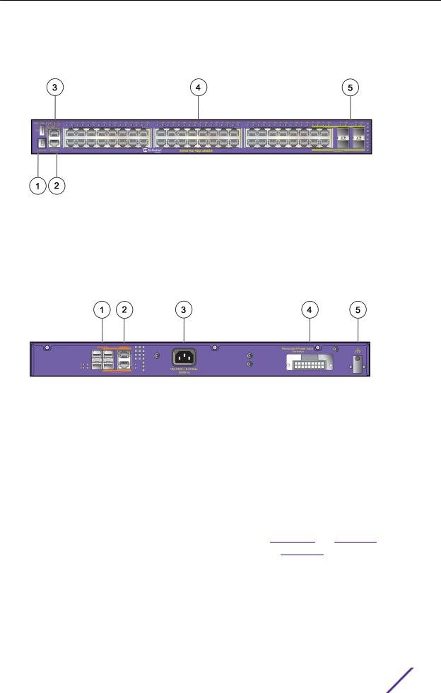
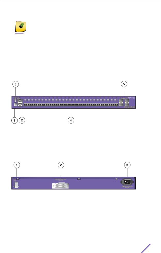
ExtremeSwitching X440-G2-48t-10GE4 Switch Ports and Slots
The ExtremeSwitching X440-G2-48t-10GE4 switch ports and slots include:
•48 front panel ports of 10/100/1000BASE-T (RJ45). Both half-duplex and full-duplex communication are supported on ports 1 through 16 and 25 through 40. The rest of the ports are full-duplex only.
•Four unpopulated front panel 1GBASE-X SFP combination ports.
•Four unpopulated rear panel 1GBASE-X SFP ports that can be upgraded to 10Gb Ethernet.
•Two 1GbE copper combination ports that can be upgraded to 10Gb Ethernet.
•Ethernet management port (10/100/1000BASE-T).
•Serial console port implemented as an RJ45 connector used to connect a terminal and perform local management.
ExtremeSwitching and Summit Switches: Hardware Installation Guide |
18 |
ExtremeSwitching and Summit Switches
•One front panel USB 2.0 port, operational on switches running ExtremeXOS version 22.2 or later.
•One rear redundant power supply connector.
Figure 11: ExtremeSwitching X440-G2-48t-10GE4 Front Panel
1 = Stack number indicator |
4 = 10/100/1000BASE-T ports |
|
|
2 = Console port/Ethernet management port |
5 = 1GBASE-X SFP combination ports |
|
|
3 = USB port (active with ExtremeXOS version 22.2 or later) |
|
|
|
Figure 12: ExtremeSwitching X440-G2-48t-10GE4 Rear Panel
1 = SFP+ ports upgradeable to 10GBASE-X |
4 = AC power input socket |
|
|
|
|
2 |
= 1GBASE-T combination ports upgradeable to 10GBASE-T |
5 = Grounding lug |
|
|
|
3 |
= Redundant power input |
|
|
|
|
ExtremeSwitching X440-G2-48p-10GE4 Switch Ports and Slots
The ExtremeSwitching X440-G2-48p-10GE4 switch ports and slots include:
•48 front panel PoE+ ports of 10/100/1000BASE-T. Both half-duplex and full-duplex communication are supported on ports 1 through 16 and 25 through 40. The rest of the ports are full-duplex only.
•Four unpopulated front panel 1GBASE-X SFP combination ports.
•Four unpopulated rear panel 1GBASE-X SFP ports that can be upgraded to 10Gb Ethernet.
•Two 1GbE copper combination ports that can be upgraded to 10Gb Ethernet.
•Ethernet management port (10/100/1000BASE-T).
•Serial console port implemented as an RJ45 connector used to connect a terminal and perform local management.
ExtremeSwitching and Summit Switches: Hardware Installation Guide |
19 |
ExtremeSwitching and Summit Switches
•One front panel USB 2.0 port, operational on switches running ExtremeXOS version 22.2 or later.
•One rear redundant power supply connector.
Figure 13: ExtremeSwitching X440-G2-48p-10GE4 Front Panel
1 = Stack number indicator |
4 = 10/100/1000BASE-T ports |
|
|
2 = Console port/Ethernet management port |
5 = 1GBASE-X SFP combination ports |
|
|
3 = USB port (active with ExtremeXOS version 22.2 or later) |
|
|
|
Figure 14: ExtremeSwitching X440-G2-48p-10GE4 Rear Panel
1 = SFP+ Ports upgradeable to 10GBASE-X |
4 = Redundant power input |
|
|
|
|
2 |
= 1GBASE-T combination ports upgradeable to 10GBASE-T |
5 = Grounding lug |
|
|
|
3 |
= AC power input socket |
|
|
|
|
ExtremeSwitching X440-G2-24t-10GE4-DC Switch Ports and Slots
The ExtremeSwitching X440-G2-24t-10GE4-DC switch ports and slots include:
•24 front panel ports of 10/100/1000BASE-T (RJ45). Both half-duplex and full-duplex communication are supported on ports 1 through 16. Ports 17 through 24 are full-duplex only.
•Four unpopulated front panel 1GBASE-X SFP combination ports.
•Four unpopulated rear panel 1GBASE-X SFP ports that can be upgraded to 10Gb Ethernet.
•Ethernet management port (10/100/1000BASE-T).
•Serial console port implemented as an RJ45 connector used to connect a terminal and perform local management.
ExtremeSwitching and Summit Switches: Hardware Installation Guide |
20 |
ExtremeSwitching and Summit Switches
•One front panel USB 2.0 port, operational on switches running ExtremeXOS version 22.2 or later.
•One rear redundant power supply connector.
Figure 15: ExtremeSwitching X440-G2-24t-10GE4-DC Front Panel
1 = Stack number indicator |
4 = 10/100/1000BASE-T ports |
|
|
|
|
2 |
= Console port/Ethernet management port |
5 = 1GBASE-X SFP combination ports |
|
|
|
3 |
= USB port (active with ExtremeXOS version 22.2 or later) |
|
|
|
|
Figure 16: ExtremeSwitching X440-G2-24t-10GE4-DC Rear Panel
1 = Grounding lug |
3 = Redundant power input |
|
|
2 = SFP+ Ports upgradeable to 10GBASE-X |
4 = DC power connector panel |
|
|
ExtremeSwitching X440-G2-48t-10GE4-DC Switch Ports and Slots
The ExtremeSwitching X440-G2-48t-10GE4-DC switch ports and slots include:
•48 front panel ports of 10/100/1000BASE-T (RJ45). Both half-duplex and full-duplex communication are supported on ports 1 through 16 and 25 through 40. The rest of the ports are full-duplex only.
•Four unpopulated front panel 1GBASE-X SFP combination ports.
•Four unpopulated rear panel 1GBASE-X SFP ports that can be upgraded to 10Gb Ethernet.
•Two 1GbE copper combination ports that can be upgraded to 10Gb Ethernet.
•Ethernet management port (10/100/1000BASE-T).
•Serial console port implemented as an RJ45 connector used to connect a terminal and perform local management.
ExtremeSwitching and Summit Switches: Hardware Installation Guide |
21 |
ExtremeSwitching and Summit Switches
•One front panel USB 2.0 port, operational on switches running ExtremeXOS version 22.2 or later.
•One rear redundant power supply connector.
Figure 17: ExtremeSwitching X440-G2-48t-10GE4-DC Front Panel
1 = Stack number indicator |
4 = 10/100/1000BASE-T ports |
|
|
|
|
2 |
= Console port/Ethernet management port |
5 = 1GBASE-X SFP combination ports |
|
|
|
3 |
= USB port (active with ExtremeXOS version 22.2 or later) |
|
|
|
|
Figure 18: ExtremeSwitching X440-G2-48t-10GE4-DC Rear Panel
1 = SFP+ Ports upgradeable to 10GBASE-X |
4 = DC power connector panel |
|
|
2 = 1GBASE-T combination ports upgradeable to 10GBASE-T |
5 = Grounding lug |
|
|
3 = Redundant power input |
|
|
|
ExtremeSwitching X440-G2-12t8fx-GE4 Switch Ports and Slots
The ExtremeSwitching X440-G2-12t8fx-GE4 switch ports and slots include:
•12 front panel 10/100/1000BASE-T ports, all of which support both half-duplex and full-duplex communication.
•Four unpopulated front panel 1GBASE-X SFP ports.
•Eight 100BASE-FX LC connectors.
Note
The LC connectors are transceivers with an LC interface.
• Ethernet management port (10/100/1000BASE-T).
ExtremeSwitching and Summit Switches: Hardware Installation Guide |
22 |
ExtremeSwitching and Summit Switches
•Serial console port implemented as an RJ45 connector used to connect a terminal and perform local management.
•One front panel USB 2.0 port, operational on switches running ExtremeXOS version 22.2 or later.
•One rear redundant power supply connector.
The X440-G2 12t8fx-GE4 switch supports an operating range from 0°C to 60°C.
Figure 19: ExtremeSwitching X440-G2-12t8fx-GE4 Front Panel
1 = Stack number indicator |
4 = 10/100/1000BASE-T ports |
|
|
|
|
2 |
= Console port/Ethernet management port |
5 = 1GBASE-X SFP ports |
|
|
|
3 |
= USB port (active with ExtremeXOS version 22.2 or later) |
6 = 100BASE-FX LC connectors |
|
|
|
Figure 20: ExtremeSwitching X440-G2-12t8fx-GE4 Rear Panel
1 = Redundant power input |
3 = AC power input socket |
2 = Grounding lug
ExtremeSwitching X440-G2-24fx-GE4 Switch Ports and Slots
The ExtremeSwitching X440-G2-24fx-GE4 switch ports and slots include:
ExtremeSwitching and Summit Switches: Hardware Installation Guide |
23 |
ExtremeSwitching and Summit Switches
• 24 front panel 100BASE-FX LC connectors.
Note
The LC connectors are transceivers with an LC interface.
•Four unpopulated front panel 1GBASE-X SFP ports.
•Ethernet management port (10/100/1000BASE-T).
•Serial console port implemented as an RJ45 connector used to connect a terminal and perform local management.
•One front panel USB 2.0 port, operational on switches running ExtremeXOS version 22.2 or later.
•One rear redundant power supply connector.
The X440-G2 24fx-GE4 switch supports an operating range from 0°C to 60°C.
Figure 21: ExtremeSwitching X440-G2-24fx-GE4 Front Panel
1 = Stack number indicator |
4 = 100BASE-FX LC connectors |
|
|
|
|
2 |
= Console port/Ethernet management port |
5 = 1GBASE-X SFP ports |
|
|
|
3 |
= USB port (active with ExtremeXOS version 22.2 or later) |
|
|
|
|
Figure 22: ExtremeSwitching X440-G2-24fx-GE4 Rear Panel
1 = Grounding lug |
3 = AC power input socket |
|
|
2 = Redundant power input |
|
|
|
ExtremeSwitching and Summit Switches: Hardware Installation Guide |
24 |
ExtremeSwitching and Summit Switches
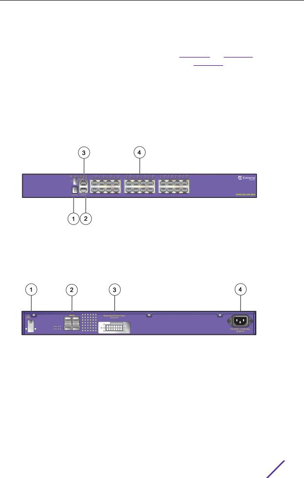
ExtremeSwitching X440-G2-24t-GE4 Switch Ports and Slots
The ExtremeSwitching X440-G2-24t-GE4 switch ports and slots include:
•24 front panel 10/100/1000BASE-T ports (RJ45). Both half-duplex and full-duplex communication are supported on ports 1 through 16. Ports 17 through 24 are full-duplex only.
•Four unpopulated front panel 1GBASE-X SFP ports.
•Ethernet management port (10/100/1000BASE-T).
•Serial console port implemented as an RJ45 connector used to connect a terminal and perform local management.
•One front panel USB 2.0 port, operational on switches running ExtremeXOS version 22.2 or later.
•One rear redundant power supply connector.
The X440-G2 24t-GE4 switch supports an operating range from 0°C to 60°C.
Figure 23: ExtremeSwitching X440-G2-24t-GE4 Front Panel
1 = Stack number indicator |
3 = USB port (active with ExtremeXOS version 22.2 or later) |
|
|
2 = Console port/Ethernet management port |
4 = 10/100/1000BASE-T ports |
|
|
Figure 24: ExtremeSwitching X440-G2-24t-GE4 Rear Panel
1 = Grounding lug |
3 = Redundant power input |
|
|
2 = 1GBASE-X SFP ports |
4 = AC power input socket |
|
|
ExtremeSwitching X440-G2 Series Switch LEDs
The following sections describe the meanings of the LEDs on the ExtremeSwitching X440-G2 series switches.
ExtremeSwitching and Summit Switches: Hardware Installation Guide |
25 |

ExtremeSwitching and Summit Switches
Table 4: X440-G2 Front Panel LEDs
Label or Type |
Color/State |
Meaning |
|
|
|
|
|
M (Management) |
Slow blinking green (1 Hz) |
Normal operation |
|
|
|
|
|
|
Fast blinking green (2 Hz) |
Power-on self test (POST) in progress |
|
|
|
or |
|
|
|
Switch diagnostics are running |
|
|
|
|
|
|
Steady green |
POST passed: system is booting image |
|
|
|
|
|
|
Blinking amber |
System is disabled: POST failed or system |
|
|
|
overheated |
|
|
|
|
|
|
Off |
No external power is attached |
|
|
|
|
|
S1, S2 (Stack Management) |
Steady green |
Link OK on the indicated stacking port |
|
|
|
|
|
|
Blinking green |
Activity on the indicated stacking port |
|
|
|
|
|
FAN |
Steady green |
Normal operation |
|
|
|
|
|
|
Blinking amber |
Failure |
|
|
|
|
|
|
Off |
No power |
|
|
|
|
|
Power Supply Unit (PSU) |
Steady green |
Normal operation |
|
|
|
|
|
|
Blinking amber |
Input or output power failure |
|
|
|
|
|
|
Off |
No board power |
|
|
|
|
|
Redundant Power Supply |
Steady green |
Normal operation |
|
(RPS) |
|
|
|
Blinking amber |
Power failure |
||
|
|||
|
|
When RPS is present, no supply from PSU |
|
|
|
|
|
|
Off |
No RPS PSU is attached |
|
|
|
|
|
Ethernet Management Port |
Blinking green (left) |
Activity on the indicated port |
|
|
|
Link OK |
|
|
|
|
|
|
Off (left) |
Activity on the indicated port |
|
|
|
|
|
|
Steady green (right) |
Link OK |
|
|
|
|
|
|
Off (right) |
No link, or port disabled |
|
|
|
|
|
Other ports |
Steady green |
Link OK |
|
|
|
|
|
|
Blinking green |
Activity on the indicated port |
|
|
|
|
|
|
Off |
No link, or port disabled |
|
|
|
|
ExtremeSwitching and Summit Switches: Hardware Installation Guide |
26 |

ExtremeSwitching and Summit Switches
Table 5: Additional Port LED Meanings for PoE Switches: X440-G2-12p-10GE4, X440- G2-24p-10GE4, and X440-G2-48p-10GE4
Label or Type |
Color/State |
Meaning |
|
|
|
All front panel ports |
Steady green |
Link is OK; port is not powered |
|
|
|
|
Steady amber |
Link is OK; port is powered; no traŠc |
|
|
|
|
Blinking green |
Link is OK and transmitting packets; port is not |
|
|
powered |
|
|
|
|
Blinking amber |
Link is OK and transmitting packets; port is |
|
|
powered |
|
|
|
|
Slow blinking amber |
No link, or disabled port; port is powered |
|
|
|
|
Alternating amber and green |
Port has a power fault |
|
|
|
|
Off |
Port is not powered, has no link, or is disabled |
|
|
|
Table 6: ExtremeSwitching X440-G2 2-digit Stack Number Indicator
Label or Type |
Color/State |
Meaning |
|
|
|
Left digit (1) |
Reserved for future use |
|
|
|
|
Right digit (1 – 8) |
Indicates the position of this switch in the ExtremeSwitching stack configuration |
|
|
|
|
|
Upper half blinking |
This switch is the stack master node |
|
|
|
|
Lower half blinking |
This switch is the stack backup node |
|
|
|
|
Lit steadily |
This switch is a standby node in the stack |
|
|
|
Summit X450-G2 Series Switches
The Summit X450-G2 series switches provide 24 or 48 Ethernet ports that deliver high-density fast Ethernet or Gigabit Ethernet connectivity using fixed 10/100/1000BASE-T ports. In addition, some models offer either 24 or 48 PoE+ ports. The X450-G2 series switches also provide four ports of SFP + 10 Gb Ethernet or four ports of SFP 1 Gb Ethernet on the front panel. Each model includes two dedicated stacking ports on the rear panel.
All X450-G2 ports are full-duplex. They do not support half-duplex operation.
The Summit X450-G2 series switches include the following base models:
•
•
•
•
•
•
•
•
Summit X450-G2-24t-GE4 switch Summit X450-G2-24t-10GE4 switch Summit X450-G2-48t-GE4 switch Summit X450-G2-48t-10GE4 switch Summit X450-G2-24p-GE4 switch Summit X450-G2-24p-10GE4 switch Summit X450-G2-48p-GE4 switch Summit X450-G2-48p-10GE4 switch
ExtremeSwitching and Summit Switches: Hardware Installation Guide |
27 |

ExtremeSwitching and Summit Switches
Each base model supports front-to-back cooling only. Switch cooling is provided by a replaceable fan module.
Note
The fan module must be ordered separately.
A serial console port on the front panel of the Summit X450-G2 series switch allows you to connect a terminal and perform local management. An Ethernet management port can be used to connect the system to a parallel management network for administration. Alternatively, you can use an Ethernet cable to connect this port directly to a laptop to view and locally manage the switch configuration. The Ethernet management port supports 10/100/1000 Mbps speeds.
The non-PoE+ switches (that is, the 24t and 48t models) have a fixed, internal power supply. The PoE+ switches (that is, the 24p and 48p models) have two power supply bays to accommodate AC power supplies. Power supplies have integrated cooling fans that operate independently of the switch fans.
For more information about the power supplies used in the Summit X450-G2 switches, see Replaceable Internal Power Supplies on page 93.
Note
Summit X450-G2 series switches do not support back-to-front (BF) power supplies, and the switches do not support the back-to-front fan module.
Summit X450-G2 series switches require ExtremeXOS version 16.1.1 or later, or version 21.1.1 or later.
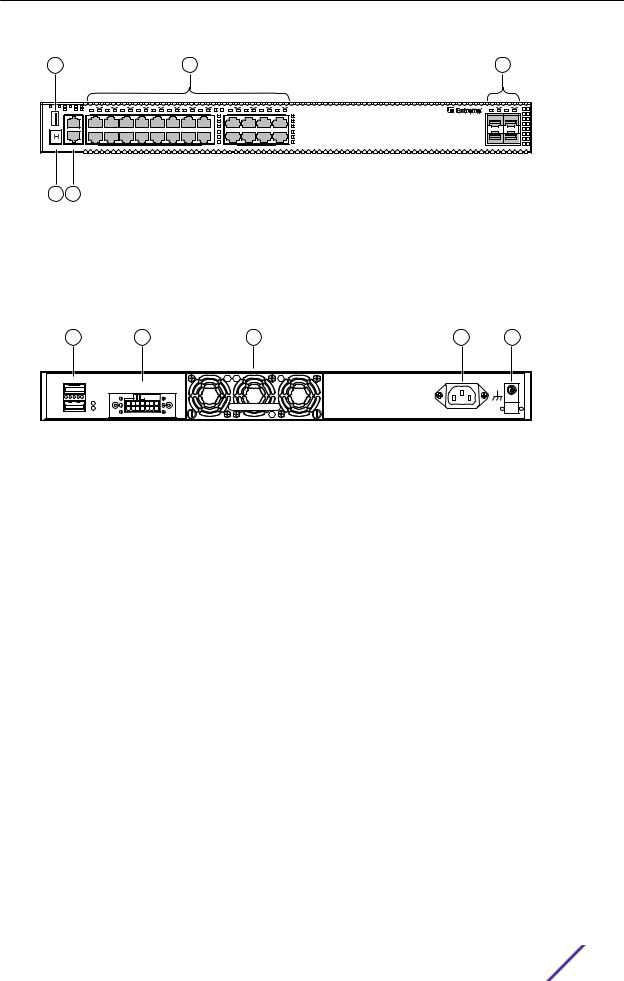
Summit X450-G2-24t-GE4 Switch Ports and Slots
The Summit X450-G2-24t-GE4 switch ports and slots include:
•24 front panel ports of 10/100/1000BASE-T (ports 1–24).
•Four front panel ports of 1GBASE-X SFP (ports 25–28).
•One front panel USB port.
•Ethernet management port 1 x 10/100/1000BASE-T.
•Serial console port implemented as an RJ45 connector used to connect a terminal and perform local management.
•One fixed power supply.
•One rear redundant power supply connector.
•One rear slot for fan module with front-to-back airflow.
•Two dedicated QSFP-form factor 21 Gb stacking ports on the rear panel.
ExtremeSwitching and Summit Switches: Hardware Installation Guide |
28 |

ExtremeSwitching and Summit Switches
3 |
4 |
5 |
MGT |
FAN |
P1 |
P2 |
S S2 |
1 |
2 |
3 |
4 |
5 |
6 |
7 |
8 |
9 |
10 |
11 |
12 |
13 |
14 |
15 |
16 |
17 |
18 |
19 |
20 |
21 |
22 |
23 |
24 |
25 |
26 |
27 |
28 |
|
|
CLK |
ACT LINK |
|
|
|
|
|
|
|
|
|
|
|
|
|
|
|
|
|
|
|
|
|
|
|
|
|
|
|
|
|
|
|
Management |
|
|
|
|
|
|
|
|
|
|
|
|
|
|
|
|
|
|
|
|
|
|
|
|
|
|
|
|
|
|
|
STACK NO. |
CONSOLE |
|
|
|
|
|
|
|
|
|
|
|
|
|
|
|
|
|
|
|
|
|
|
|
|
Summit™ X450-G2-24t-GE4 |
GbE S FP |
|
|||
1 2
Figure 25: Summit X450-G2-24t-GE4 Front Panel
1 = Stack number indicator |
|
4 = 10/100/1000BASE-T ports |
|||
|
|
|
|||
2 |
= Console port/Ethernet management port |
5 = SFP 1GBASE-X ports |
|||
|
|
|
|
|
|
3 |
= USB port |
|
|
|
|
|
|
|
|
|
|
|
1 |
2 |
3 |
4 |
5 |
SummitStack-V84 |
Redundant Power Input |
! See Manual |
1 |
2 |
Figure 26: Summit X450-G2-24t-GE4 Rear Panel
1 = 21 Gb stacking ports (QSFP+) |
4 = AC power input connector |
|
|
2 = Redundant power supply (RPS) connector |
5 = Grounding screw |
|
|
3 = Front-to-back fan module slot |
|
|
|
Summit X450-G2-24t-10GE4 Switch Ports and Slots
The Summit X450-G2-24t-10GE4 switch ports and slots include:
•24 front panel ports of 10/100/1000BASE-T (ports 1–24).
•Four front panel ports of 10GBASE-X SFP+ (ports 25–28, with ports 27 and 28 configurable to be stacking ports). The SFP+ ports are dual speed (1 Gb/10 Gb).
•Front panel USB port.
•Ethernet management port 1 x 10/100/1000BASE-T.
•Serial console port implemented as an RJ45 connector used to connect a terminal and perform local management.
•One fixed power supply.
•One rear redundant power supply connector.
•One rear slot for fan module with front-to-back airflow.
•Two dedicated QSFP-form factor 21 Gb stacking ports on the rear panel.
ExtremeSwitching and Summit Switches: Hardware Installation Guide |
29 |
ExtremeSwitching and Summit Switches
3 |
|
|
|
|
|
|
|
|
|
|
|
|
4 |
|
|
|
|
|
|
|
|
|
5 |
|
MGT FAN P1 P2 |
S S2 |
1 |
2 |
3 |
4 |
5 |
6 |
7 |
8 |
9 |
10 |
11 12 |
13 14 |
15 |
16 |
17 18 |
19 20 |
21 22 |
23 |
24 |
25 |
26 |
27 |
28 |
CLK |
ACT LINK |
|
|
|
|
|
|
|
|
|
|
|
|
|
|
|
|
|
|
|
|
|
|
|
Management |
|
|
|
|
|
|
|
|
|
|
|
|
|
|
|
|
|
|
|
|
|
|
|
|
STACK NO. |
CONSOLE |
Summit™ X450-G2-24t-10GE4 |
10GbES FP+ |
1 2
Figure 27: Summit X450-G2-24t-10GE4 Front Panel
1 = Stack number indicator |
|
4 = 10/100/1000BASE-T ports |
||
|
|
|||
2 = Console port/Ethernet management port |
5 = SFP+ 10GBASE-X ports |
|||
|
|
|
|
|
3 = USB port |
|
|
|
|
|
|
|
|
|
1 |
2 |
3 |
4 |
5 |
SummitStack-V84 |
Redundant Power Input |
! See Manual |
1 |
2 |
Figure 28: Summit X450-G2-24t-10GE4 Rear Panel
1 = 21 Gb stacking ports (QSFP+) |
4 = AC power input connector |
|
|
2 = Redundant power supply (RPS) connector |
5 = Grounding screw |
|
|
3 = Front-to-back fan module slot |
|
|
|
Summit X450-G2-48t-GE4 Switch Ports and Slots
The Summit X450-G2-48t-GE4 switch ports and slots include:
•48 front panel ports of 10/100/1000BASE-T (ports 1–48).
•Four front panel ports of 1GBASE-X SFP (ports 49–52).
•One front panel USB port.
•Ethernet management port 1 x 10/100/1000BASE-T.
•Serial console port implemented as an RJ45 connector used to connect a terminal and perform local management.
•One fixed power supply.
•One rear redundant power supply connector.
•One rear slot for fan module with front-to-back airflow.
•Two dedicated QSFP-form factor 21 Gb stacking ports on the rear panel.
ExtremeSwitching and Summit Switches: Hardware Installation Guide |
30 |
Loading...