


 Loading...
ExtremeWireless™
AP3935i & AP3935e Installation Guide
P/N 9034915
December 2015
Copyright © 2015 Extreme Networks, Inc. All Rights Reserved.
Legal Notices
Extreme Networks, Inc. reserves the right to make changes in specifications and other information contained in this document and its website without prior notice. The reader should in all cases consult representatives of Extreme Networks to determine whether any such changes have been made.
The hardware, firmware, software or any specifications described or referred to in this document are subject to change without notice.
Trademarks
Extreme Networks and the Extreme Networks logo are trademarks or registered trademarks of Extreme Networks, Inc. in the United States and/or other countries.
All other names (including any product names) mentioned in this document are the property of their respective owners and may be trademarks or registered trademarks of their respective companies/owners.
For additional information about Extreme Networks trademarks, go to: www.extremenetworks.com/company/legal/trademarks/
Support
For product support, including documentation, visit: www.extremenetworks.com/support/
Contact
Extreme Networks, Inc.
145 Rio Robles
San Jose, CA 95134
Tel: +1 408-579-2800
Toll-free: +1 888-257-3000

|
Contents |
About This Guide |
|
Who Should Use This Guide .............................................................................................................................. |
v |
How to Use This Guide ....................................................................................................................................... |
v |
Related Documents ........................................................................................................................................... |
vi |
Typographical Conventions ............................................................................................................................... |
vi |
Getting Help ...................................................................................................................................................... |
vii |
Chapter 1: Introduction |
|
About the AP3935i and AP3935e ...................................................................................................................... |
1 |
AP3935 Overview .............................................................................................................................................. |
2 |
AP3935 LED Indicators ............................................................................................................................... |
4 |
Architectural Features ....................................................................................................................................... |
5 |
Console Port ............................................................................................................................................... |
5 |
LAN Port ...................................................................................................................................................... |
5 |
Reset Switch ............................................................................................................................................... |
5 |
Kensington Lock Slot .................................................................................................................................. |
6 |
Chapter 2: Installation |
|
Unpacking the AP3935 ...................................................................................................................................... |
7 |
Accessories ....................................................................................................................................................... |
7 |
Access Point Installation Procedures ................................................................................................................ |
8 |
Mounting the AP3935 to a Drop Ceiling ...................................................................................................... |
8 |
Mounting the AP3935 to a Wall ................................................................................................................... |
9 |
Mounting the AP using the Optional Mounting Bracket ............................................................................. |
10 |
LAN/Console Connections ........................................................................................................................ |
11 |
Connecting an External DC Power Supply to the AP3935 ........................................................................ |
11 |
Configuring AP3935e Channel Settings .......................................................................................................... |
12 |
Determine the Antenna Model .................................................................................................................. |
12 |
Configure Radio RF Port ........................................................................................................................... |
12 |
Configure Radio Channel .......................................................................................................................... |
14 |
Configure Radio Transmit (Tx) Power ....................................................................................................... |
16 |
Appendix A: Specifications |
|
External Power Supplies ................................................................................................................................. |
19 |
Internal Antenna APs ....................................................................................................................................... |
20 |
Internal Antenna Access Points ................................................................................................................ |
20 |
Horizontal Radiation Pattern 2.4 GHz (XZ Plane) ..................................................................................... |
21 |
Vertical Radiation Pattern 2.4 GHz (XY Plane) ......................................................................................... |
21 |
Vertical Radiation Pattern 2.4 GHz (YZ Plane) ......................................................................................... |
22 |
Horizontal Radiation Pattern 5 GHz (XZ Plane) ........................................................................................ |
22 |
Vertical Radiation Pattern 5 GHz (XY Plane) ............................................................................................ |
23 |
Vertical Radiation Pattern 5 GHz (YZ Plane) ............................................................................................ |
23 |
External Antennas ........................................................................................................................................... |
24 |
Appendix B: Regulatory Information |
|
ExtremeWireless AP3935i and AP3935e ........................................................................................................ |
25 |
United States ............................................................................................................................................. |
25 |
FCC Declaration of Conformity Statement .......................................................................................... |
25 |
USA Conformance Standards ............................................................................................................. |
26 |
FCC RF Radiation Exposure Statement.............................................................................................. |
27 |
ExtremeWireless™ AP3935 Installation Guide i
|
Canada ...................................................................................................................................................... |
27 |
|
Industry Canada Compliance Statement............................................................................................. |
27 |
|
Canada Conformance Standards ........................................................................................................ |
28 |
|
European Community ............................................................................................................................... |
29 |
|
Declaration of Conformity in Languages of the European Community................................................ |
29 |
|
European Conformance Standards ..................................................................................................... |
30 |
|
Conditions of use in the European Community ................................................................................... |
31 |
|
European Spectrum Usage Rules ....................................................................................................... |
32 |
|
Certifications of Other Countries ............................................................................................................... |
33 |
Tables |
|
|
3-1 |
Typographical Conventions ................................................................................................................... |
vi |
1-1 |
AP3935 LED Indications........................................................................................................................ |
4 |
2-1 |
AP3935 Package Contents ................................................................................................................... |
7 |
A-1 |
Specifications for the AP3935i and AP3935e...................................................................................... |
19 |
A-2 |
Universal Specifications for an External Power Supply....................................................................... |
20 |
A-3 |
AP3935i Internal Antennas.................................................................................................................. |
20 |
A-4 |
Certified External Antennas for AP3935e............................................................................................ |
24 |
B-1 |
European Spectrum Usage Rules ....................................................................................................... |
32 |
Figures |
|
|
1-1 |
ExtremeWireless AP3935i top view....................................................................................................... |
2 |
1-2 |
ExtremeWireless AP3935e top view ..................................................................................................... |
3 |
1-3 |
AP3935 bottom view.............................................................................................................................. |
3 |
1-4 |
AP3935 LEDs ........................................................................................................................................ |
4 |
1-5 |
Kensington Lock slot ............................................................................................................................. |
6 |
2-1 |
Attaching Mount Bracket to the Access Point........................................................................................ |
8 |
2-2 |
Attaching the AP3935i on a drop ceiling T-bar rail ................................................................................ |
9 |
2-3 |
Mounting the AP3935 to a Flat Wall. ................................................................................................... |
10 |
2-4 |
Mounting sequence with mounting bracket (30513, WS-MBI-WALL03) ............................................. |
10 |
2-5 |
3935e Access Point bottom view......................................................................................................... |
11 |
2-6 |
AP Properties for the AP3935e ........................................................................................................... |
13 |
2-7 |
AP3935e Radio 1 Properties: Base Settings....................................................................................... |
15 |
2-8 |
AP3935e Radio 1 Properties: Channel Plan setting............................................................................ |
16 |
2-9 |
AP3935e Radio 1 Properties: Max TX Power setting.......................................................................... |
17 |
ii
About This Guide
The guide describes how to mount and connect cables to the ExtremeWireless AP3935 access point. In addition, this guide provides information on the product certifications and national approvals for the AP3935 access point.
NOTE
This guide does not provide information on configuration of the access points.
For information on how to configure the access points, see the ExtremeWireless
User Guide.
Who Should Use This Guide
WARNING
Electrical Hazard: Only qualified personnel should install or service this unit.
Riesgo Electrico: Nada mas personal capacitado debe de instalar o darle servicio a esta unida.
Elektrischer Gefahrenhinweis: Installationen oder Servicearbeiten sollten nur durch ausgebildetes und qualifiziertes Personal vorgenommen werden.
How to Use This Guide
Read through this guide completely to familiarize yourself with its contents and to gain an understanding of the features and capabilities of the AP3935 access point. A general working knowledge of data communications networks is helpful when setting up this product.
This preface provides an overview of this guide, defines the conventions used in this document, and instructs how to obtain technical support from Extreme Networks. To locate information about various subjects in this guide, refer to the following table.
For... |
Refer to... |
|
|
An overview of the AP3935 features. |
Chapter 1, Introduction |
|
|
Instructions to mount the AP3935, connect cables, and |
Chapter 2, Installation |
connect power. Instructions are also included to mount and |
|
connect the optional Power Supply. |
|
|
|
Specifications, environmental requirements, and physical |
Appendix A, Specifications |
properties of the AP3935 and optional Power Supply. |
|
|
|
Regulatory certifications and national approvals. |
Appendix B, Regulatory Information |
|
|
ExtremeWireless™ AP3935 Installation Guide v

Related Documents
The following document can be obtained from the World Wide Web in Adobe Acrobat Portable Document Format (PDF) at the following location:
https://extranet.extremenetworks.com/downloads/
•ExtremeWireless User Guide
Typographical Conventions
The following typographical conventions and icons are used in this document.
Table 3-1 Typographical Conventions
blue type |
Indicates a hypertext link. When reading this document online, click the text in blue to go to |
|
the referenced figure, table, or section. |
Lowercase x Indicates the general use of an alphanumeric character (for example, AP39xx, the x’s indicate a combination of numbers or letters).
Note: Calls the reader’s attention to any item of information that may be of special importance.
Caution: Contains information essential to avoid damage to the equipment.
Precaución: Contiene información esencial para prevenir dañar el equipo.
Achtung: Verweißt auf wichtige Informationen zum Schutz gegen Beschädigungen.
Warning: Warns against an action that could result in personal injury or death.
Advertencia: Advierte contra una acción que pudiera resultar en lesión corporal o la muerte.
Warnhinweis: Warnung vor Handlungen, die zu Verletzung von Personen oder gar Todesfällen führen können!
vi

Getting Help
For additional support related to the AP3935 or this document, contact Extreme Networks using one of the following methods:
Web |
www.Extreme Networks.com/support/ |
Phone |
1-800-872-8440 (toll-free in U.S. and Canada) |
|
or 1-603-952-5000 |
|
For the Extreme Networks Support toll-free number in your country: |
|
www.Extreme Networks.com/support/ |
|
|
Before contacting Extreme Networks for technical support, have the following data ready:
•Your Extreme Networks service contract number
•A description of the failure
•A description of any action(s) already taken to resolve the problem (for example, changing mode switches or rebooting the unit)
•The serial and revision numbers of all involved Extreme Networks products in the network
•A description of your network environment (such as layout, cable type, other relevant environmental information)
•Network load and frame size at the time of trouble (if known)
•The device history (for example, if you have returned the device before, or if this is a recurring problem)
•Any previous Return Material Authorization (RMA) numbers
ExtremeWireless™ AP3935 Installation Guide vii

viii

1
Introduction
This installation guide provides an overview and installation instructions for the ExtremeWireless Access Points AP3935i and AP3935e.
For information about... |
Refer to page... |
|
|
About the AP3935i and AP3935e |
1-1 |
|
|
AP3935 Overview |
1-2 |
|
|
Architectural Features |
1-5 |
|
|
About the AP3935i and AP3935e
The AP3935 is designed to extend your Wireless LAN around indoor locations. The AP3935 supports the 802.11ac and 802.11n wireless standards, with full backward compatibility with legacy 802.11a, and 802.11b/g devices.
The AP3935 interoperates fully with Wireless LANs, including support for VoWLAN, branch office mode, guest services, RTLS, availability, and mobility features. The operating temperature: 0 50C.
The AP3935i and AP3935e have the following features in common:
•Both support two MIMO 4x4 (up to four 802.11ac spatial streams).
•They provide two single band radios for dual band, concurrent operation, optimized for indoor antenna coverage:
–5 GHz (Radio 1) in any of the following modes: IEEE802.11ac, a/b/g and/or n
–2.4 GHz (Radio 2) in any of the following modes: IEEE802.11ac, a/b/g and/or n
•They are enclosed in a rectangular, compact case.
•Both models can be mounted on walls and drop/suspended ceilings.
•They provide 80 MHz Bandwidth at 2.4/5 GHz operation (Channel Bonding).
•Power is provided through two Ethernet ports (LAN port). This is the preferred method of powering the AP on ceiling and wall installations. The AP3935 can also be powered by an external DC power supply by plugging the supply’s input jack into the DC In port.
ExtremeWireless™ AP3935 Installation Guide 1

NOTE
The AP3935 comes in two models: the AP3935i has 8 internal single-band antennas while the AP3935e has 8 external RSMA connectors for connecting external antennas. Within this document, any reference to AP3935 applies to both models.
AP3935 Overview
The AP3935 access point is available in two models:
•AP3935i contains eight internal single band antennas
•AP3935e contains eight external RSMA connectors for optional external antennas, for greater range and coverage versatility
Figure 1 1 on page 2 shows the top view of the AP3935i and Figure 1 2 on page 3 shows the top view of the AP3935e.
Figure 1 3 on page 3 shows the bottom view of the AP3935e. The bottom view shows the location of the LAN ports, console port, external power supply connector, and reset switch.The bottom panel is the same for both models, but there are no external antenna RSMA connectors on the AP3935i.
Figure 1 4 on page 4 illustrates the AP3935 LEDs.
Figure 1-1 ExtremeWireless AP3935i top view
2 AP3935 Overview

Figure 1-2 ExtremeWireless AP3935e top view
Figure 1-3 AP3935 bottom view
1 |
Reset Button |
3 |
LAN Ethernet Ports 1 and 2 |
2 |
Console Port |
4 |
External Power DC 12V |
ExtremeWireless™ AP3935 Installation Guide 3
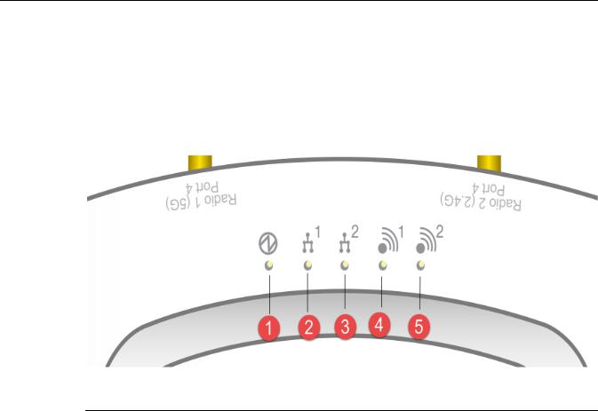
AP3935 LED Indicators
Both models of the AP3935 have the LED indicators, shown in Figure 1 4 below. The LEDs provide status information, described in Table 1 1, on the current state of the AP3935. For more information, see the ExtremeWireless User Guide.
Figure 1-4 AP3935 LEDs
1 |
Status |
4 |
Radio 1 (5 GHz) |
2 |
LAN 1 (Ethernet 1) |
5 |
Radio 2 (2.4 GHz) |
3LAN 2 (Ethernet 2)
Table 1-1 AP3935 LED Indications
LED |
Status |
Description |
|
|
|
1 (AP status) |
On Green |
Indicates the AP3935 is working |
|
|
normally. |
|
|
|
|
Flashing Green |
Indicates: |
|
|
• running a self test |
|
|
• loading software program |
|
|
|
|
On Amber |
Indicates a CPU/system failure. |
4 AP3935 Overview

Table 1-1 AP3935 LED Indications
LED |
Status |
Description |
|
|
|
|
|
2 |
(Ethernet link state) LAN 1 |
On Green |
Indicates a valid 10Mbps or 100Mbps |
|
|
|
Ethernet link. |
|
|
|
|
|
|
On Amber |
Indicates a valid 1Gbps Ethernet link. |
|
|
|
|
|
|
Off |
Indicates the link is down. |
|
|
|
|
3 |
(Ethernet link state) LAN 2 |
On Green |
Indicates a valid 10Mbps or 100Mbps |
|
|
|
Ethernet link. |
|
|
|
|
|
|
On Amber |
Indicates a valid 1Gbps Ethernet link. |
|
|
|
|
|
|
Off |
Indicates the link is down. |
|
|
|
|
4 |
(Radio 2 status) |
On Green |
Indicates Radio 2 is enabled. |
|
|
|
|
|
|
Off |
Indicates Radio 2 is not on. |
|
|
|
|
5 |
(Radio 1 status) |
On Green |
Indicates Radio 1 is enabled. |
|
|
|
|
|
|
Off |
Indicates Radio 1 is not on. |
|
|
|
|
Architectural Features
Console Port
The AP3935 i and e models both include a single RJ45 console port (shown in Figure 1 3 on page 3) for debug purposes. This port enables connection of a console device to the AP through a serial cable. The console device can be a PC or workstation running a VT 100 terminal adapter emulator, or a VT 100 terminal.
LAN Port
The AP3935 has two 10/100/1000BaseT RJ45 LAN ports (see Figure 1 3 on page 3) that can be attached directly to a 10/100/1000BaseT LAN segment. This segment must conform to the IEEE 802.3 or 802.3u specifications.
The APs appear as Ethernet nodes and perform a bridging function by moving packets from the wired LAN to remote workstations on the wireless infrastructure.
The LAN ports also support power over Ethernet PoE 802.3at for full performance; (802.3af for low performance mode). Refer to “Installation” on page 7, for information on supplying power to the AP network port from a network device, such as a switch, that provides Power over Ethernet (PoE).
Reset Switch
The AP3935 provides a Reset Switch to reset or restore factory default configurations. Use a pointed object to press the switch button through the hole.(See Figure 1 3 on page 3). If you hold down the button for less than 5 seconds, the AP performs a software interrupt, causing it to drop all connections and reset. If you hold the button down for 5 seconds or more, any configuration changes are removed, and the factory default configuration restores to the AP.
ExtremeWireless™ AP3935 Installation Guide 5
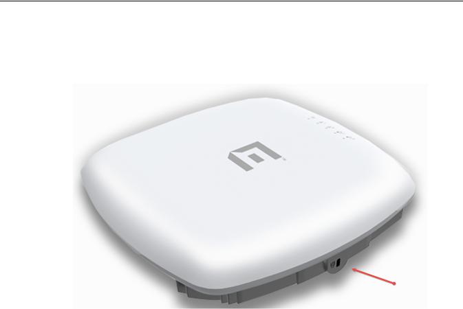
Kensington Lock Slot
There is a slot for a Kensington lock on the side of the AP (Figure 1 5). See the Kensington lock documentation for instructions on use of the lock.
Figure 1-5 Kensington Lock slot
6 Architectural Features
Loading...