


 Loading...
Summit Family Hardware
Installation Guide
for Switches Supported by ExtremeXOS 16 or Earlier
121141-03
Published October 2017
Copyright © 2017 Extreme Networks, Inc. All rights reserved.
Legal Notice
Extreme Networks, Inc. reserves the right to make changes in specifications and other information contained in this document and its website without prior notice. The reader should in all cases consult representatives of Extreme Networks to determine whether any such changes have been made.
The hardware, firmware, software or any specifications described or referred to in this document are subject to change without notice.
Trademarks
Extreme Networks and the Extreme Networks logo are trademarks or registered trademarks of Extreme Networks, Inc. in the United States and/or other countries.
All other names (including any product names) mentioned in this document are the property of their respective owners and may be trademarks or registered trademarks of their respective companies/owners.
For additional information on Extreme Networks trademarks, please see: www.extremenetworks.com/company/legal/trademarks
Software Licensing
Some software files have been licensed under certain open source or third-party licenses. Enduser license agreements and open source declarations can be found at: www.extremenetworks.com/support/policies/software-licensing
Support
For product support, phone the Global Technical Assistance Center (GTAC) at 1-800-998-2408 (toll-free in U.S. and Canada) or +1-408-579-2826. For the support phone number in other countries, visit: http://www.extremenetworks.com/support/contact/
For product documentation online, visit: https://www.extremenetworks.com/documentation/

Table of Contents |
|
Preface......................................................................................................................................... |
7 |
Audience.................................................................................................................................................................................... |
7 |
Conventions............................................................................................................................................................................. |
7 |
Providing Feedback to Us................................................................................................................................................ |
9 |
Getting Help............................................................................................................................................................................ |
9 |
Related Publications.......................................................................................................................................................... |
10 |
Chapter 1: Summit Switches..................................................................................................... |
11 |
Overview of the Summit Switches.............................................................................................................................. |
12 |
Summit X150 Series Switches........................................................................................................................................ |
13 |
Summit X250e Series Switches.................................................................................................................................... |
18 |
Summit X350 Series Switches...................................................................................................................................... |
31 |
Summit X430 Series Switches..................................................................................................................................... |
36 |
Summit X440 Series Switches..................................................................................................................................... |
42 |
Summit X450, X450a, and X450e Series Switches.......................................................................................... |
66 |
Summit X450-G2 Series Switches............................................................................................................................. |
88 |
Summit X460 Series Switches..................................................................................................................................... |
99 |
Summit X460-G2 Series Switches........................................................................................................................... |
107 |
Summit X480 Series Switches..................................................................................................................................... |
121 |
Summit X650 Series Switches.................................................................................................................................... |
126 |
Summit X670 Series Switches.................................................................................................................................... |
129 |
Summit X670-G2 Series Switches............................................................................................................................ |
135 |
Summit X770 Series Switches.................................................................................................................................... |
139 |
Pluggable Interfaces for Summit Switches.......................................................................................................... |
143 |
Chapter 2: Power Supplies for Use with Summit Switches.............................................. |
145 |
External Power Supplies for Summit Switches.................................................................................................. |
145 |
Replaceable Internal Power Supplies for Summit Switches........................................................................ |
159 |
Chapter 3: Option Cards and Versatile Interface Modules............................................... |
165 |
Summit XGM-2xn Option Card.................................................................................................................................. |
166 |
Summit XGM2-2xn Option Card................................................................................................................................ |
167 |
Summit XGM2-2xf Option Card................................................................................................................................. |
168 |
Summit XGM2-2sf Option Card................................................................................................................................. |
169 |
Summit XGM2-2bt Option Card................................................................................................................................ |
170 |
Versatile Interface Modules for the Summit X480 Series Switches......................................................... |
170 |
Versatile Interface Modules for the Summit X650 Series Switches......................................................... |
173 |
Optional Ports for the Summit X460 Series Switches.................................................................................... |
177 |
Summit X460 Series Stacking Modules................................................................................................................ |
180 |
Optional Ports for the X460-G2 Series Switches............................................................................................. |
180 |
VIM4-40G4X Versatile Interface Module for the Summit X670 Switch................................................ |
184 |
Chapter 4: Site Preparation.................................................................................................. |
186 |
Planning Your Site............................................................................................................................................................ |
186 |
Operating Environment Requirements................................................................................................................... |
187 |
Rack Specifications and Recommendations........................................................................................................ |
191 |
Evaluating and Meeting Cable Requirements..................................................................................................... |
192 |
Meeting Power Requirements.................................................................................................................................... |
198 |
Following Applicable Industry Standards............................................................................................................. |
201 |
Summit Family Hardware Installation Guide |
3 |

Table of Contents
Chapter 5: Building Stacks................................................................................................... |
202 |
Introduction to Stacking.............................................................................................................................................. |
202 |
Planning to Create Your Stack.................................................................................................................................... |
214 |
Setting up the Physical Stack.................................................................................................................................... |
239 |
Chapter 6: Installing Summit Switches............................................................................... |
263 |
Safety Considerations for Installing Switches.................................................................................................... |
263 |
Pre-installation Requirements................................................................................................................................... |
264 |
Installing a Summit Family Switch........................................................................................................................... |
265 |
Installing Internal Power Supplies............................................................................................................................ |
285 |
Connecting Network Interface Cables.................................................................................................................... |
312 |
Performing Initial Management Tasks..................................................................................................................... |
313 |
Chapter 7: Installing Summit External Power Supplies.................................................... |
317 |
Safety Considerations for Installing Power Supplies....................................................................................... |
317 |
Pre-installation Requirements..................................................................................................................................... |
318 |
Installing an EPS-150DC External Power Module (with EPS-T2)............................................................... |
318 |
Installing an EPS-160 External Power Module (with EPS-T)....................................................................... |
323 |
Installing an EPS-500 External Power Supply Unit......................................................................................... |
326 |
Installing an EPS-600LS External Power Module............................................................................................ |
328 |
Installing an EPS-C2 Power Supply......................................................................................................................... |
333 |
Installing an EPS-LD External Power Supply...................................................................................................... |
341 |
Installing an STK-RPS-150PS Redundant Power Supply.............................................................................. |
344 |
Installing an RPS-500p Redundant Power Supply......................................................................................... |
349 |
Chapter 8: Installing Port Option Cards and VIMs............................................................ |
354 |
Installing a Summit Port Option Card................................................................................................................... |
354 |
Installing an Option Card in Slot B of a Summit X460 Series Switch.................................................... |
357 |
Installing a Versatile Interface Module in a Summit X460, X480, X650, or X670 Series |
|
Switch.................................................................................................................................................................................... |
358 |
Installing a Versatile Interface Module or Clock Module in a Summit X460-G2 Series Switch.360 |
|
Chapter 9: Replacing AC Power Supplies.......................................................................... |
362 |
Replacing a Summit 300 W AC Power Supply................................................................................................. |
362 |
Replacing a Summit 715 W AC Power Supply................................................................................................... |
364 |
Replacing a Summit 450 W or 550 W AC Power Supply........................................................................... |
366 |
Replacing a Summit 750 W AC Power Supply................................................................................................. |
368 |
Replacing a Summit 850 W AC Power Supply................................................................................................. |
372 |
Replacing a Summit 1100 W AC Power Supply................................................................................................ |
374 |
Removing an EPS-LD or EPS-500 Power Supply........................................................................................... |
376 |
Removing an EPS-160 Power Supply from an EPS-T.................................................................................... |
376 |
Removing an EPS-600LS Power Module............................................................................................................. |
377 |
Removing an STK-RPS-150PS Redundant Power Supply............................................................................ |
377 |
Chapter 10: Replacing DC Power Supplies........................................................................ |
378 |
Replacing a Summit 300 W DC Power Supply................................................................................................. |
378 |
Replacing a Summit 450 W or 550 W DC Power Supply........................................................................... |
384 |
Replacing a Summit 850 W DC Power Supply.................................................................................................. |
391 |
Removing an EPS-150DC Power Module from an EPS-T2 Tray................................................................ |
395 |
Chapter 11: Replacing Fan Modules.................................................................................... |
396 |
Pre-Installation Requirements................................................................................................................................... |
396 |
Summit Family Hardware Installation Guide |
4 |

Table of Contents
Airflow Direction Requirements............................................................................................................................... |
396 |
Replacing a Fan Module............................................................................................................................................... |
396 |
Chapter 12: Replacing Port Option Cards and VIMs......................................................... |
398 |
Replacing a Stacking Module or Option Card in Slot B of a Summit X460 Series Switch......... |
398 |
Replacing an XGM3/XGM3S Series Port Option Card in a Summit X460 Series Switch............. |
399 |
Replacing a Versatile Interface Module (VIM) in a Summit X480, X650 or X670 Series |
|
Switch................................................................................................................................................................................... |
400 |
Replacing an XGM or XGM2 Series Port Option Card................................................................................... |
402 |
Replacing a Versatile Interface Module or Clock Module in a Summit X460-G2 Series |
|
Switch................................................................................................................................................................................... |
403 |
Chapter 13: Removing Summit Switches........................................................................... |
405 |
Removing an AC Power Supply............................................................................................................................... |
405 |
Removing a DC Power Supply................................................................................................................................. |
406 |
Removing a Switch from a Rack.............................................................................................................................. |
407 |
Appendix A: Safety Information......................................................................................... |
409 |
Considerations Before Installing.............................................................................................................................. |
409 |
General Safety Precautions......................................................................................................................................... |
410 |
Maintenance Safety........................................................................................................................................................... |
411 |
Cable Routing for LAN Systems................................................................................................................................. |
411 |
Installing Power Supply Units and Connecting Power................................................................................... |
412 |
Selecting Power Supply Cords................................................................................................................................... |
413 |
Battery Replacement and Disposal......................................................................................................................... |
414 |
Battery Warning - Taiwan............................................................................................................................................. |
414 |
Fiber Optic Ports and Optical Safety..................................................................................................................... |
414 |
Sicherheitshinweise.......................................................................................................................................................... |
415 |
Überlegungen vor der Installation............................................................................................................................ |
416 |
Allgemeine Sicherheitshinweise................................................................................................................................ |
416 |
Sicherheit bei Wartungsarbeiten............................................................................................................................... |
417 |
Kabelverlegung für LAN-Systeme............................................................................................................................ |
417 |
Installation der Netzteile und Netzanschluss...................................................................................................... |
418 |
Auswahl der Netzkabel................................................................................................................................................. |
420 |
Wechseln und Entsorgen der Batterie.................................................................................................................. |
420 |
LWL-Ports und optische Sicherheit....................................................................................................................... |
420 |
Konformität von GBIC, SFP (Mini-GBIC), QSFP+, XENPAK und XFP..................................................... |
421 |
Mögliche Netzanschlussgerätund Lüftereinsatz-Konfigurationen für X770-32q.......................... |
422 |
Appendix B: Technical Specifications................................................................................ |
424 |
Summit X150 Series Switches Technical Specifications............................................................................... |
425 |
Summit X250e Series Switches Technical Specifications............................................................................ |
429 |
Summit X350 Series Switches Technical Specifications.............................................................................. |
436 |
Summit X430 Series Switches Technical Specifications.............................................................................. |
439 |
Summit X440 Series Switches Technical Specifications............................................................................. |
444 |
Summit X450 Series Switches Technical Specifications.............................................................................. |
454 |
Summit X450a Series Switches Technical Specifications........................................................................... |
456 |
Summit X450e Series Switches Technical Specifications........................................................................... |
462 |
Summit X450-G2 Series Switches Technical Specifications...................................................................... |
466 |
Summit X460 Series Switches Technical Specifications.............................................................................. |
472 |
Summit X460-G2 Series Switches Technical Specifications...................................................................... |
479 |
Summit X480 Series Switches Technical Specifications.............................................................................. |
487 |
Summit Family Hardware Installation Guide |
5 |

Table of Contents
Summit X650 Series Switches Technical Specifications.............................................................................. |
499 |
Summit X670 Series Switches Technical Specifications.............................................................................. |
509 |
Summit X670-G2 Series Switches Technical Specifications........................................................................ |
515 |
Summit X770 Series Switches Technical Specifications................................................................................ |
519 |
STK-RPS-150PS and RPS Shelves Technical Specifications........................................................................ |
523 |
Summit 300 W Power Supplies Technical Specifications............................................................................ |
525 |
Summit 350 W Power Supplies Technical Specifications............................................................................ |
527 |
Summit 450 W Power Supplies Technical Specifications............................................................................ |
528 |
Summit 550 W Power Supplies Technical Specifications........................................................................... |
530 |
Summit 550 W Power Supplies for X670-G2 Switches................................................................................. |
531 |
Summit 715 W Power Supplies Technical Specifications.............................................................................. |
533 |
Summit 750 W Power Supplies Technical Specifications............................................................................ |
534 |
Summit 850 W Power Supplies Technical Specifications............................................................................ |
535 |
Summit 1100 W Power Supplies Technical Specifications........................................................................... |
536 |
Summit External Power Supplies Technical Specifications......................................................................... |
537 |
EPS-C2 Redundant Power Supply Technical Specifications....................................................................... |
541 |
RPS-500p Redundant Power Supply Technical Specifications................................................................ |
542 |
Power Cord Requirements for AC-Powered Switches and AC Power Supplies............................... |
543 |
Console Connector Pinouts........................................................................................................................................ |
544 |
Taiwan Warnings.............................................................................................................................................................. |
546 |
Japan (VCCI Class A).................................................................................................................................................... |
546 |
Korea EMC Statement................................................................................................................................................... |
547 |
Glossary......................................................................................................................................... |
548 |
Index........................................................................................................................................ |
552 |
Summit Family Hardware Installation Guide |
6 |

Preface
This guide provides the instructions and supporting information needed to install the following Extreme Networks® Summit® family switches:
•Summit X150 Series Switches on page 13
•Summit X250e Series Switches on page 18
•Summit X350 Series Switches on page 31
•Summit X430 Series Switches on page 36
•Summit X440 Series Switches on page 42
•Summit X450, X450a, and X450e Series Switches on page 66
•Summit X450-G2 Series Switches on page 88
•Summit X460 Series Switches on page 99
•Summit X460-G2 Series Switches on page 107
•Summit X480 Series Switches on page 121
•Summit X650 Series Switches on page 126
•Summit X670 Series Switches on page 129
•Summit X670-G2 Series Switches on page 135
•Summit X770 Series Switches on page 139
The guide includes information about site preparation, switch functionality, and switch operation.
Audience
This guide is intended for use by network administrators responsible for installing and setting up network equipment. It assumes a basic working knowledge of:
•
•
•
•
•
•
Local area networks (LANs) Ethernet concepts
Ethernet switching and bridging concepts Routing concepts
SNMP (Simple Network Management Protocol)
Basic equipment installation procedures
See the ExtremeXOS 22.3 User Guide and the ExtremeXOS 22.3 Command Reference Guide for information about configuring Summit switches.
Note
If the information in an installation note or release note shipped with your Extreme Networks equipment differs from the information in this guide, follow the installation or release note.
Conventions
This section discusses the conventions used in this guide.
Summit Family Hardware Installation Guide |
7 |

Preface
Text Conventions
The following tables list text conventions that are used throughout this guide.
Table 1: Notice Icons
Icon |
Notice Type |
Alerts you to... |
|
|
|
|
General Notice |
Helpful tips and notices for using the product. |
|
|
|
|
Note |
Important features or instructions. |
|
|
|
|
Caution |
Risk of personal injury, system damage, or loss of data. |
|
|
|
|
Warning |
Risk of severe personal injury. |
|
|
|
|
New |
This command or section is new for this release. |
|
|
|
Table 2: Text Conventions
Convention |
Description |
|
|
Screen displays |
This typeface indicates command syntax, or represents information as it appears on the |
|
screen. |
|
|
The words enter and |
When you see the word “enter” in this guide, you must type something, and then press |
type |
the Return or Enter key. Do not press the Return or Enter key when an instruction |
|
simply says “type.” |
|
|
[Key] names |
Key names are written with brackets, such as [Return] or [Esc]. If you must press two |
|
or more keys simultaneously, the key names are linked with a plus sign (+). Example: |
|
Press [Ctrl]+[Alt]+[Del] |
|
|
Words in italicized type |
Italics emphasize a point or denote new terms at the place where they are defined in |
|
the text. Italics are also used when referring to publication titles. |
|
|
Platform-Dependent Conventions
Unless otherwise noted, all information applies to all platforms supported by ExtremeXOS® software, which are the following:
•
•
•
ExtremeSwitching® switches Summit® switches SummitStack™
When a feature or feature implementation applies to specific platforms, the specific platform is noted in the heading for the section describing that implementation in the ExtremeXOS command documentation (see the Extreme Documentation page at http:// documentation.extremenetworks.com). In many cases, although the command is available on all
Summit Family Hardware Installation Guide |
8 |

Preface
platforms, each platform uses specific keywords. These keywords specific to each platform are shown in the Syntax Description and discussed in the Usage Guidelines sections.
Terminology
When features, functionality, or operation is specific to a switch family, such as ExtremeSwitching™ or Summit®, the family name is used. Explanations about features and operations that are the same across all product families simply refer to the product as the switch.
Providing Feedback to Us
We are always striving to improve our documentation and help you work better, so we want to hear from you! We welcome all feedback but especially want to know about:
•Content errors or confusing or conflicting information.
•Ideas for improvements to our documentation so you can find the information you need faster.
•Broken links or usability issues.
If you would like to provide feedback to the Extreme Networks Information Development team about this document, please contact us using our short online feedback form. You can also email us directly at internalinfodev@extremenetworks.com.
Getting Help
If you require assistance, contact Extreme Networks using one of the following methods:
•GTAC (Global Technical Assistance Center) for Immediate Support
•Phone: 1-800-998-2408 (toll-free in U.S. and Canada) or +1 408-579-2826. For the support phone number in your country, visit: www.extremenetworks.com/support/contact
•Email: support@extremenetworks.com. To expedite your message, enter the product name or model number in the subject line.
•GTAC Knowledge — Get on-demand and tested resolutions from the GTAC Knowledgebase, or create a help case if you need more guidance.
•The Hub — A forum for Extreme customers to connect with one another, get questions answered, share ideas and feedback, and get problems solved. This community is monitored by Extreme Networks employees, but is not intended to replace specific guidance from GTAC.
•Support Portal — Manage cases, downloads, service contracts, product licensing, and training and certifications.
Before contacting Extreme Networks for technical support, have the following information ready:
•Your Extreme Networks service contract number and/or serial numbers for all involved Extreme Networks products
•A description of the failure
•A description of any action(s) already taken to resolve the problem
•A description of your network environment (such as layout, cable type, other relevant environmental information)
•Network load at the time of trouble (if known)
Summit Family Hardware Installation Guide |
9 |

Preface
•The device history (for example, if you have returned the device before, or if this is a recurring problem)
•Any related RMA (Return Material Authorization) numbers
Related Publications
ExtremeSwitching X8, ExtremeSwitching, and E4G Hardware
Documentation
•E4G Series Routers Hardware Installation Guide
•Extreme Hardware/Software Compatibility and Recommendation Matrices
•Extreme Networks Pluggable Transceivers Installation Guide
•ExtremeSwitching X8 Series Switches Hardware Installation Guide
•ExtremeXOS 16.2 User Guide
•ExtremeXOS 16.2 Command Reference Guide
•ExtremeSwitching and Summit Switches: Hardware Installation Guide for Switches Using ExtremeXOS 21.1 or Later
•Environmental Guidelines for ExtremeSwitching Products
Summit Family Hardware Installation Guide |
10 |
1 Summit Switches
Overview of the Summit Switches
Summit X150 Series Switches
Summit X250e Series Switches
Summit X350 Series Switches
Summit X430 Series Switches
Summit X440 Series Switches
Summit X450, X450a, and X450e Series Switches
Summit X450-G2 Series Switches
Summit X460 Series Switches
Summit X460-G2 Series Switches
Summit X480 Series Switches
Summit X650 Series Switches
Summit X670 Series Switches
Summit X670-G2 Series Switches
Summit X770 Series Switches
Pluggable Interfaces for Summit Switches
The Summit switches are compact enclosures 1.75 inches high (1 U). Each switch model provides between 8 and 72 high-density copper or fiber optic ports operating at speeds up to 40 Gbps. Many models also provide combination copper/fiber uplink ports. PoE connections and options for adding 10Gbps or 40-Gbps uplink connections are available on some models.
Many Summit switches include high-speed stacking interfaces that allow you to connect up to eight switches into a single SummitStack management entity. Models are available for AC or DC power connection; all switches make provision for redundant power supplies. Most models have connections for optional external redundant power supplies: the Summit X450-G2 (PoE models), X460, X460-G2, X480, X650, X670, X670-G2, and X770 switches provide two bays for pluggable power supplies.
Most models are available in versions that are compliant with the Trade Agreements Act (TAA); these versions are identified by a -TAA su‰x on the model number. Functionally, the TAA-compliant models are completely equivalent to the matching versions that are not TAA-compliant. In all feature descriptions, references to a specific Summit switch model also apply to the equivalent TAA-compliant model.
This document describes switches that are supported on ExtremeXOS version 16 and earlier. For information about other ExtremeSwitching and Summit switches, refer to the ExtremeSwitching and Summit Switches: Hardware Installation Guide for Switches Using ExtremeXOS 21.1 or Later.
The following sections contain general information about the switches:
Summit Family Hardware Installation Guide |
11 |

Summit Switches
•
•
•
•
•
•
•
•
•
•
•
•
•
•
Summit X150 Series Switches on page 13 Summit X250e Series Switches on page 18 Summit X350 Series Switches on page 31 Summit X430 Series Switches on page 36 Summit X440 Series Switches on page 42
Summit X450, X450a, and X450e Series Switches on page 66 Summit X450-G2 Series Switches on page 88
Summit X460 Series Switches on page 99 Summit X460-G2 Series Switches on page 107 Summit X480 Series Switches on page 121 Summit X650 Series Switches on page 126 Summit X670 Series Switches on page 129 Summit X670-G2 Series Switches on page 135 Summit X770 Series Switches on page 139
Overview of the Summit Switches
The following sections describe the Summit switches and summarize the features available in each series.
Model numbers for the switches are in the following format:
<Series>-<number of front-panel I/O ports><port type><internal power supply type>
•The number of ports ranges from 8 to 72.
•The port type can be t (copper), p (copper providing PoE (Power over Ethernet)), q (QSFP+), or x (fiber).
•For models with integral power supplies, the power supply type can be AC (no designation) or DC.
Models with pluggable power supplies can accommodate either AC or DC supplies and have no power designation in their model numbers.
Note
See the ExtremeXOS 22.3 User Guide and the ExtremeXOS 22.3 Command Reference Guide for feature-specific information about the Summit switches and for information regarding switch configuration.
Combination Ports and Failover
Summit switches provide 2, 4, or 12 uplink ports implemented as combination ports that pair a copper port using RJ45 connectors with an optical port using LC connectors.
The copper port operates as an autonegotiating 10/100/1000BASE-T port. The optical port allows Gigabit Ethernet uplink connections through Extreme Networks small form factor pluggable (SFP) interface modules. See the individual switch descriptions for the port numbers of the combination ports on each switch model.
Summit Family Hardware Installation Guide |
12 |

Summit Switches
Summit switches support automatic failover from an active fiber port to a copper backup or from an active copper port to a fiber port. If one of the uplink connections fails, the Summit uplink connection automatically fails over to the second connection. To set up a redundant link on a combination port, connect the active 1000BASE-T and fiber links to both the RJ45 and SFP interfaces of that port.
Gigabit Ethernet uplink redundancy on the Summit switches follows these rules:
•With both the SFP and 1000BASE-T interfaces connected on a combination port, only one interface can be activated. The other is inactive.
•If only one interface is connected, the switch activates the connected interface.
•The switch determines whether the port uses the fiber or copper connection based on the order in which the connectors are inserted into the switch. When the switch senses that an SFP and a copper connector are inserted, the switch enables the uplink redundancy feature. For example, if you first connect copper ports x and y on a switch, and then insert SFPs into ports x and y, the switch assigns the copper ports as active ports and the fiber ports as redundant ports.
Hardware identifies when a link is lost and responds by swapping the primary and redundant ports to maintain stability. After a failover occurs, the switch keeps the current port assignment until another failure occurs or a user changes the assignment using the CLI. For more information about configuring automatic failover on combination ports, see the ExtremeXOS 22.3 User Guide.
Summit X150 Series Switches
The Summit X150 series switches provide 24 or 48 fixed 10/100BASE-T Ethernet ports that deliver highdensity copper connectivity at 2.4 Gbps or 4.8 Gbps.
Models are available with PoE and without PoE. Each Summit X150 series switch has two combination ports that provide 10/100/1000 BASE-T or SFP connectivity for 2 Gbps of copper or fiber connectivity. A serial console port on the front panel allows you to connect a terminal and perform local management. On the back of the switch, an Ethernet management port can be used to connect the system to a parallel management network for administration. Alternatively, you can use an Ethernet cable to connect this port directly to a laptop to view and locally manage the switch configurations.
The rear panel of the switch provides an AC power input socket and a redundant power connector. The internal power supply operates from 100 VAC to 240 VAC. The switch automatically adjusts to the supply voltage. The redundant power connector allows you to connect the switch to the EPS-160 or EPS-500 external power supply. When a compatible external power supply is used with the Summit X150 series switch, the internal and external power supplies are fully fault tolerant and load-sharing. If one power supply fails, the other power supply will provide su‰cient power to operate the switch.
The Summit X150e series switches include the following switch models:
•
•
•
•
Summit X150-24t Switch Ports and Slots on page 14 Summit X150-24t-TAA switch
Summit X150-24p Switch Ports and Slots on page 15 Summit X150-24p-TAA switch
Summit Family Hardware Installation Guide |
13 |
Summit Switches
•Summit X150-48t Switch Ports and Slots on page 16
•Summit X150-48t-TAA switch
Note
In the descriptions that follow, references to a Summit X150 series model number also apply to the equivalent TAA-compliant switch version.
Summit X150 series switches require an ExtremeXOS version of at least 12.0.2.25 but not greater than 15.3.x.
Summit X150-24t Switch Ports and Slots
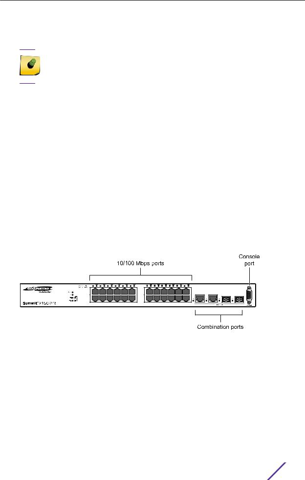
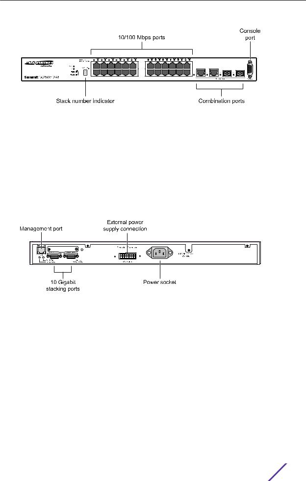
The front panel of the Summit X150-24t switch includes:
•Twenty-four fixed autosensing 10/100BASE-T ports (ports 1–24) that provide 2.4 Gbps of highdensity copper connectivity.
•Two combination ports (ports 25–26) using RJ45 connectors and SFPs to provide 2 Gbps of copper or fiber connectivity.
For more information about combination ports, see Combination Ports and Failover on page 12. For information about SFPs, see the Extreme Networks Pluggable Transceivers Installation Guide.
•LEDs to indicate port status and switch operating conditions.
For a description of the LEDs and their operation, see Summit X150 Series Switch LEDs on page 17.
•Serial console port used to connect a terminal and perform local management.
Figure 1: Summit X150-24t Switch Front Panel
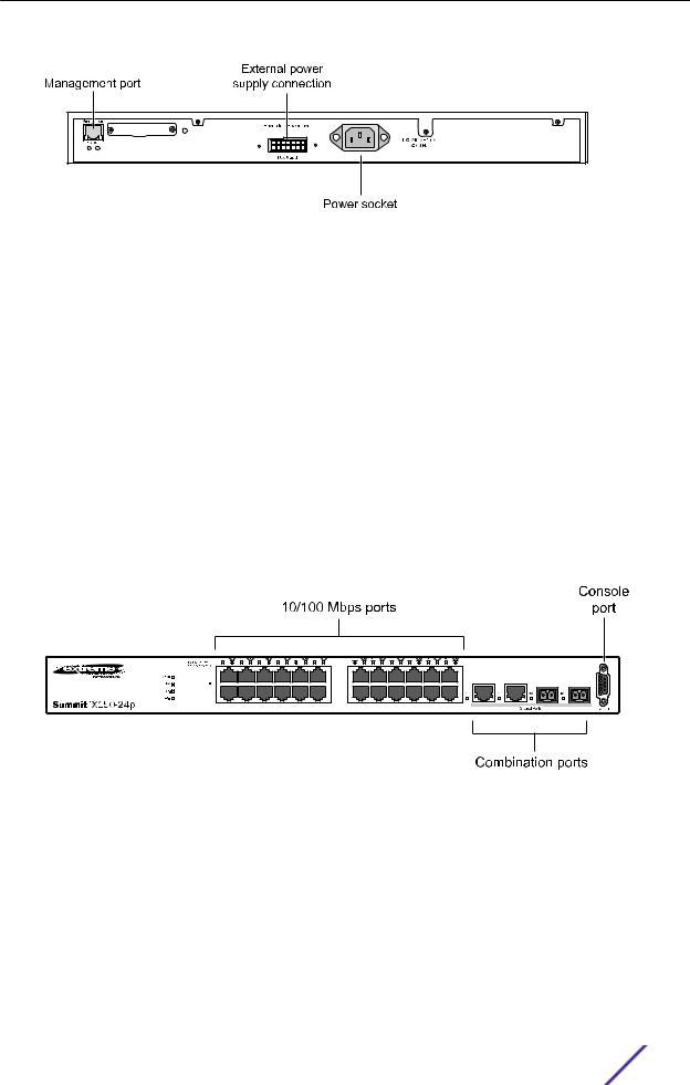
The rear panel of the Summit X150-24t switch (shown in Figure 2 on page 15) includes:
•Ethernet management port with associated LEDs .
•Redundant power input connector for optional connection to the EPS-160 External Power Module.
See EPS-160 External Power Module (with EPS-T) on page 150 for more information. The connecting redundant power supply cable is shipped with the EPS-160 unit.
•AC power input socket.
The internal AC power supply operates from 100 VAC to 240 VAC.
Summit Family Hardware Installation Guide |
14 |
Summit Switches
Figure 2: Summit X150-24t Switch Rear Panel
Summit X150-24p Switch Ports and Slots
The front panel of the Summit X150-24p switch includes:
•Twenty-four fixed autosensing 10/100BASE-T PoE ports (ports 1–24). In addition to 4 Gbps of highdensity copper connectivity, these ports also provide a full 15.4 Watts of PoE per port.
•Two combination ports (ports 25–26) using RJ45 connectors and SFPs to provide 2 Gbps of copper or fiber connectivity.
For more information about combination ports, see Combination Ports and Failover on page 12. For information about SFPs, see the Extreme Networks Pluggable Transceivers Installation Guide.
•LEDs to indicate port status and switch operating conditions.
For a description of the LEDs and their operation, see Summit X150 Series Switch LEDs on page 17.
•Serial console port used to connect a terminal and perform local management.
Figure 3: Summit X150-24p Switch Front Panel
The rear panel of the Summit X150-24p switch includes:
•Ethernet management port with associated LEDs.
•Redundant power input connector for optional connection to the EPS-500 External Power Supply (Model No. 10911) with full PoE power support.
The connecting redundant power supply cable is shipped with the EPS-500 unit. See EPS-500 External Power Supply Unit on page 151 for more information.
•AC power input socket.
The internal AC power supply operates from 100 VAC to 240 VAC.
Summit Family Hardware Installation Guide |
15 |
Summit Switches
Figure 4: Summit X150-24p Switch Rear Panel
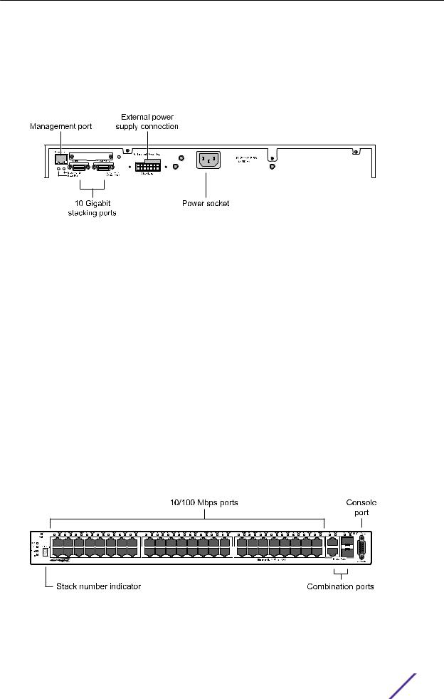
Summit X150-48t Switch Ports and Slots
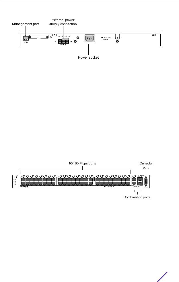
The front panel of the Summit X150-48t switch includes:
•Forty-eight fixed autosensing 10/100BASE-T ports (ports 1–48) that provide 4.8 Gbps of highdensity copper connectivity.
•Two combination ports (ports 49–50) using RJ45 connectors and SFPs to provide 2 Gbps of copper or fiber connectivity.
For more information about combination ports, see Combination Ports and Failover on page 12. For information about SFPs, see the Extreme Networks Pluggable Transceivers Installation Guide.
•LEDs to indicate port status and switch operating conditions.
For a description of the LEDs and their operation, see Summit X150 Series Switch LEDs on page 17.
•Serial console port used to connect a terminal and perform local management.
Figure 5: Summit X150-48t Switch Front Panel
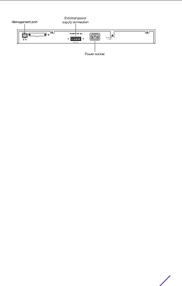
The rear panel of the Summit X150-48t switch (Figure 6 on page 17) includes:
•Management port with associated LEDs.
•Redundant power input connector for optional connection to the EPS-160 External Power Module.
The connecting redundant power supply cable is shipped with the EPS-160 unit. See EPS-160 External Power Module (with EPS-T) on page 150 for more information.
•AC power input socket.
The internal AC power supply operates from 100 VAC to 240 VAC.
Summit Family Hardware Installation Guide |
16 |
Summit Switches
Figure 6: Summit X150-48t Switch Rear Panel
Summit X150 Series Switch LEDs
The following sections describe the meanings of the LEDs on Summit X150 switches.
LEDs on the Summit X150 Series Switches
Table 3: Front Panel
Label or Type |
Color/State |
Meaning |
|
|
|
|
|
MGMT |
Blinking green (fast) |
Power-on self-test (POST) in progress. |
|
|
|
|
|
|
Steady green |
POST passed. System is booting image. |
|
|
|
|
|
|
Blinking green (slow) |
Normal operation. |
|
|
|
|
|
|
Blinking amber |
Switch diagnostics are running. |
|
|
|
or |
|
|
|
System is disabled. POST failed or system overheated. |
|
|
|
|
|
|
Off |
No external power attached. |
|
|
|
|
|
FAN |
Steady green |
Normal operation. |
|
|
|
|
|
|
Blinking amber |
Fan failure. Switch will continue to operate unless it overheats. |
|
|
|
|
|
|
Off |
No power. |
|
|
|
|
|
PSU-I |
Steady green |
Normal operation. |
|
(Internal power |
|
|
|
Blinking amber |
Failure. |
||
supply) |
|||
|
|
||
|
Off |
No power. |
|
|
|
|
|
PSU-E |
Steady green |
Normal operation. |
|
(External power |
|
|
|
Blinking amber |
Failure. |
||
supply) |
|||
|
|
||
|
Off |
No external power attached. |
|
|
|
|
|
Port number |
Steady green |
Link is OK. |
|
1 – 24 or 1 – 48 |
|
|
|
Blinking green |
Port is transmitting packets. |
||
|
|||
|
|
|
|
|
Off |
Link is not present, or port is disabled. |
|
|
|
|
|
Port number |
Steady green |
Link is OK. |
|
25, 26 or 49, 50 |
|
|
|
Blinking green |
Activity. |
||
(Shared ports) |
|||
|
|
||
|
Off |
Link is not present, or port is disabled. |
|
|
|
|
Summit Family Hardware Installation Guide |
17 |

Summit Switches
Table 4: Additional Port LED Meanings for PoE Switch: Summit X150-24p
Label or Type |
Color/State |
Meaning |
|
|
|
All front-panel ports |
Steady green |
Link OK; port is not powered. |
|
|
|
|
Steady amber |
Link is OK; port is powered; no tra‰c. |
|
|
|
|
Blinking green |
Link is OK and transmitting packets; port is not powered. |
|
|
|
|
Blinking amber |
Link is OK and transmitting packets; port is powered. |
|
|
|
|
Slow blinking amber |
No link, or disabled port; port is powered. |
|
|
|
|
Alternating amber and |
Port has a power fault. |
|
green |
|
|
|
|
|
Off |
Port is not powered, has no link, or is disabled. |
|
|
|
Table 5: Rear Panel
Label or Type |
Color/State |
Meaning |
|
|
|
Management Port |
Right LED: |
Link is OK. |
|
Steady green |
|
|
|
|
|
Left LED: |
Activity. |
|
Blinking green |
|
|
|
|
|
Both LEDs off |
Link is not present. |
|
|
|
Summit X250e Series Switches
The Summit X250e series switches provide 24 or 48 Ethernet ports that deliver high-density fast Ethernet connectivity using fixed 10/100/1000BASE-T ports or installable small form pluggable (SFP) optical modules.
Fixed-port models are available either with or without PoE. Each Summit X250e series switch has two combination ports that provide 10/100/1000 BASE-T or SFP connectivity for 2 Gbps of copper or fiber connectivity. A serial console port on the front panel allows you to connect a terminal and perform local management. An Ethernet management port can be used to connect the system to a parallel management network for administration. Alternatively, you can use an Ethernet cable to connect this port directly to a laptop to view and locally manage the switch configurations.
On the back of the switch, two high-speed stacking ports allow you to combine multiple units into a single SummitStack management entity. The rear panel also provides an AC or DC power input socket and a redundant power connector. (See specific switch descriptions for more information about the power options.) The switch automatically adjusts to the supply voltage. The redundant power connector allows you to connect the switch to the EPS-160, EPS-500, or EPS-150DC external power supply. When a compatible external power supply is used with the Summit X250e series switch, the internal and external power supplies are fully fault tolerant and load-sharing. If one power supply fails, the other power supply will provide su‰cient power to operate the switch.
The Summit X250e series switches include the following models:
•
•
Summit X250e-24t Switch Ports and Slots on page 19 Summit X250e-24t-TAA switch
Summit Family Hardware Installation Guide |
18 |

Summit Switches
•Summit X250e-24tDC Switch Ports and Slots on page 20
•Summit X250e-24tDC-TAA switch
•Summit X250e-24x Switch Ports and Slots on page 21
•Summit X250e-24x-TAA switch
•Summit X250e-24xDC Switch Ports and Slots on page 22
•Summit X250e-24xDC-TAA switch
•Summit X250e-24p Switch Ports and Slots on page 24
•Summit X250e-24p-TAA switch
•Summit X250e-48t Switch Ports and Slots on page 25
•Summit X250e-48t-TAA switch
•Summit X250e-48tDC Switch Ports and Slots on page 26
•Summit X250e-48tDC-TAA switch
•Summit X250e-48p Switch Ports and Slots on page 27
•Summit X250e-48p-TAA switch
Note
In the descriptions that follow, references to a Summit X250e series model number also apply to the equivalent TAA-compliant switch version.
Summit X250e series switches require an ExtremeXOS version of at least 12.0.1.11 but not greater than 15.3.x.
Summit X250e-24t Switch Ports and Slots
The front panel of the Summit X250e-24t switch includes:
•Twenty-four fixed autosensing 10/100BASE-T ports (ports 1–24) that provide 2.4 Gbps of highdensity copper connectivity.
•Two combination ports (ports 25–26) using RJ45 connectors and SFPs to provide 2 Gbps of copper or fiber connectivity.
For more information about combination ports, see Combination Ports and Failover on page 12. For information about SFPs, see the Extreme Networks Pluggable Transceivers Installation Guide.
•LEDs to indicate port status and switch operating conditions.
For a description of the LEDs and their operation, see Summit X250e Series Switch LEDs on page 29.
•Stack number indicator showing the position of this switch in a stacked configuration.
•Serial console port used to connect a terminal and perform local management.
Summit Family Hardware Installation Guide |
19 |
Summit Switches
Figure 7: Summit X250e-24t Switch Front Panel
The rear panel of the Summit X250e-24t switch (shown in Figure 8 on page 20) includes:
•Ethernet management port with associated LEDs.
•Two high-performance stacking ports with associated LEDs.
•Redundant power input connector for optional connection to the EPS-160 External Power Module.
The connecting redundant power supply cable is shipped with the EPS-160 unit. See EPS-160 External Power Module (with EPS-T) on page 150 for more information.
•AC power input socket.
The internal AC power supply operates from 100 VAC to 240 VAC.
Figure 8: Summit X250e-24t Switch Rear Panel
Summit X250e-24tDC Switch Ports and Slots
The front panel of the Summit X250e-24tDC switch includes:
•Twenty-four fixed autosensing 10/100BASE-T ports (ports 1–24) that provide 2.4 Gbps of highdensity copper connectivity.
•Two combination ports (ports 25–26) using RJ45 connectors and SFPs to provide 2 Gbps of copper or fiber connectivity.
For more information about combination ports, see Combination Ports and Failover on page 12. For information about SFPs, see the Extreme Networks Pluggable Transceivers Installation Guide.
•LEDs to indicate port status and switch operating conditions.
For a description of the LEDs and their operation, see Summit X250e Series Switch LEDs on page 29.
Summit Family Hardware Installation Guide |
20 |

Summit Switches
•Stack number indicator showing the position of this switch in a stacked configuration.
•Serial console port used to connect a terminal and perform local management.
Figure 9: Summit X250e-24tDC Switch Front Panel
The rear panel of the Summit X250e-24tDC switch (shown in Figure 10 on page 21) includes:
•Ethernet management port with associated LEDs.
•Two high-performance stacking ports with associated LEDs.
•Redundant power input connector for optional connection to the EPS-150DC External Power Module (Model No. 10909).
The connecting redundant power supply cable is shipped with the EPS-150DC unit. See EPS-150DC External Power Module (with EPS-T2) on page 149 for more information.
•DC power input socket.
The internal power supply operates from -36 VDC to -72 VDC.
•Grounding lug.
Note
For centralized DC power connection, this product is intended to be installed in a restricted access location (such as a dedicated equipment room, equipment closet, or central o‰ce) in accordance with Articles 110-16, 110-17, and 110-18 of the National Electric Code, ANSI/NFPA 70.
Figure 10: Summit X250e-24tDC Switch Rear Panel
Summit X250e-24x Switch Ports and Slots
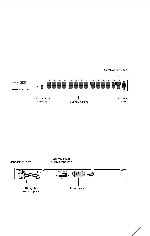
The front panel of the Summit X250e-24x switch includes:
Summit Family Hardware Installation Guide |
21 |
Summit Switches
•Twenty-four 100BASE-FX ports (ports 1–24) that provide 2.4 Gbps of high-density fiber connectivity.
•Two combination ports (ports 25–26) using RJ45 connectors and SFPs to provide 2 Gbps of copper or fiber connectivity.
For more information about combination ports, see Combination Ports and Failover on page 12. For information about SFPs, see the Extreme Networks Pluggable Transceivers Installation Guide.
•LEDs to indicate port status and switch operating conditions.
For a description of the LEDs and their operation, see Summit X250e Series Switch LEDs on page 29.
•Stack number indicator showing the position of this switch in a stacked configuration.
•Serial console port used to connect a terminal and perform local management.
Figure 11: Summit X250e-24x Switch Front Panel
The rear panel of the Summit X250e-24x switch (shown in Figure 12 on page 22) includes:
•Ethernet management port with associated LEDs.
•Two high-performance stacking ports with associated LEDs.
•Redundant power input connector for use with the EPS-160 External Power Module.
The connecting redundant power supply cable is shipped with the EPS-160 unit. See EPS-160 External Power Module (with EPS-T) on page 150 for more information.
•AC power input socket.
The internal AC power supply operates from 100 VAC to 240 VAC.
Figure 12: Summit X250e-24x Switch Rear Panel
Summit X250e-24xDC Switch Ports and Slots
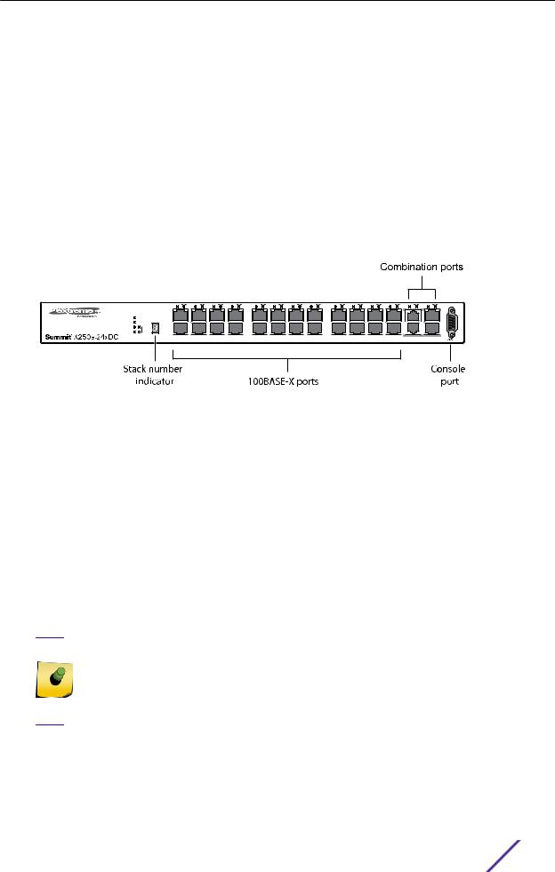
The front panel of the Summit X250e-24xDC switch includes:
Summit Family Hardware Installation Guide |
22 |
Summit Switches
•Twenty-four 100BASE-FX ports (ports 1–24) that provide 2.4 Gbps of high-density fiber connectivity.
•Two combination ports (ports 25–26) using RJ45 connectors and SFPs to provide 2 Gbps of copper or fiber connectivity.
For more information about combination ports, see Combination Ports and Failover on page 12. For information about SFPs, see the Extreme Networks Pluggable Transceivers Installation Guide.
•LEDs to indicate port status and switch operating conditions.
For a description of the LEDs and their operation, see Summit X250e Series Switch LEDs on page 29.
•Stack number indicator showing the position of this switch in a stacked configuration.
•Serial console port used to connect a terminal and perform local management.
Figure 13: Summit X250e-24xDC Switch Front Panel
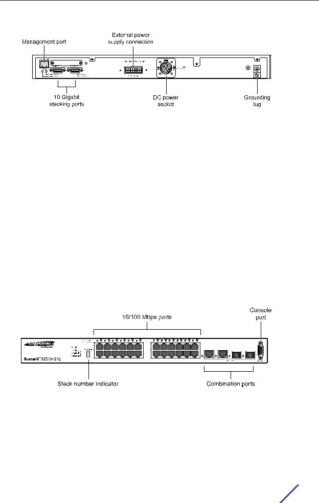
The rear panel of the Summit X250e-24xDC switch (Figure 14 on page 24) includes:
•Ethernet management port with associated LEDs.
•Two high-performance stacking ports with associated LEDs.
•Redundant power input connector for use with the EPS-150DC External Power Module (Model No. 10909).
The connecting redundant power supply cable is shipped with the EPS-150DC unit. See EPS-150DC External Power Module (with EPS-T2) on page 149 for more information.
•DC power input socket.
The internal power supply operates from -36 VDC to -72 V DC.
•Grounding lug.
Note
For centralized DC power connection, this product is intended to be installed in a restricted access location (such as a dedicated equipment room, equipment closet, or central o‰ce) in accordance with Articles 110-16, 110-17, and 110-18 of the National Electric Code, ANSI/NFPA 70.
Summit Family Hardware Installation Guide |
23 |
Summit Switches
Figure 14: Summit X250e-24xDC Switch Rear Panel
Summit X250e-24p Switch Ports and Slots
The front panel of the Summit X250e-24p switch includes:
•Twenty-four fixed autosensing 10/100BASE-T PoE ports (ports 1–24). In addition to 2.4 Gbps of high-density copper connectivity, these ports also provide a full 15.4 Watts of PoE per port.
•Two combination ports (ports 25–26) using RJ45 connectors and SFPs to provide 2 Gbps of copper or fiber connectivity.
For more information about combination ports, see Combination Ports and Failover on page 12. For information about SFPs, see the Extreme Networks Pluggable Transceivers Installation Guide.
•LEDs to indicate port status and switch operating conditions.
For a description of the LEDs and their operation, see Summit X250e Series Switch LEDs on page 29.
•Stack number indicator showing the position of this switch in a stacked configuration.
•Serial console port used to connect a terminal and perform local management.
Figure 15: Summit X250e-24p Switch Front Panel
The rear panel of the Summit X250e-24p switch (shown in Figure 16 on page 25) includes:
•Ethernet management port with associated LEDs.
•Two high-performance stacking ports with associated LEDs.
•Redundant power input connector for use with the EPS-500 External Power Supply (Model No. 10911) with full PoE power support.
Summit Family Hardware Installation Guide |
24 |
Summit Switches
The connecting redundant power supply cable is shipped with the EPS-500 unit. See EPS-500 External Power Supply Unit on page 151 for more information.
•AC power input socket.
The internal AC power supply operates from 100 VAC to 240 VAC.
Figure 16: Summit X250e-24p Switch Rear Panel
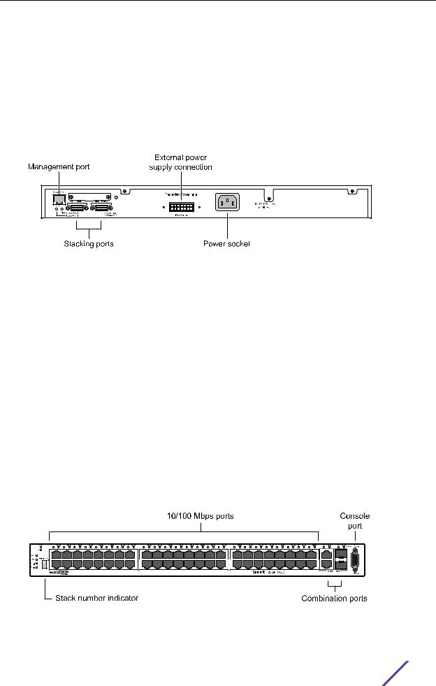
Summit X250e-48t Switch Ports and Slots
The front panel of the Summit X250e-48t switch includes:
•Forty-eight fixed autosensing 10/100BASE-T ports (ports 1–48) that provide 4.8 Gbps of highdensity copper connectivity.
•Two combination ports (ports 49–50) using RJ45 connectors and SFPs to provide 2 Gbps of copper or fiber connectivity.
For more information about combination ports, see Combination Ports and Failover on page 12. For information about SFPs, see the Extreme Networks Pluggable Transceivers Installation Guide.
•LEDs to indicate port status and switch operating conditions.
For a description of the LEDs and their operation, see Summit X250e Series Switch LEDs on page 29.
•Stack number indicator showing the position of this switch in a stacked configuration.
•Serial console port used to connect a terminal and perform local management.
Figure 17: Summit X250e-48t Switch Front Panel
The rear panel of the Summit X250e-48t switch (Figure 18 on page 26) includes:
Summit Family Hardware Installation Guide |
25 |
Summit Switches
•Management port with associated LEDs.
•Two high-performance stacking ports with associated LEDs.
•Redundant power input connector for optional connection to the EPS-160 External Power Module.
The connecting redundant power supply cable is shipped with the EPS-160 unit. See EPS-160 External Power Module (with EPS-T) on page 150 for more information.
•AC power input socket.
The internal AC power supply operates from 100 VAC to 240 VAC.
Figure 18: Summit X250e-48t Switch Rear Panel
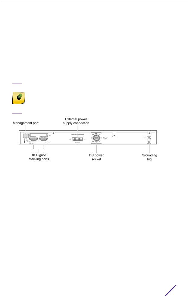
Summit X250e-48tDC Switch Ports and Slots
The front panel of the Summit X250e-48tDC switch includes:
•Forty-eight fixed autosensing 10/100BASE-T ports (ports 1–48) that provide 4.8 Gbps of highdensity copper connectivity.
•Two combination ports (ports 49–50) using RJ45 connectors and SFPs to provide 2 Gbps of copper or fiber connectivity.
For more information about combination ports, see Combination Ports and Failover on page 12. For information about SFPs, see the Extreme Networks Pluggable Transceivers Installation Guide.
•LEDs to indicate port status and switch operating conditions
For a description of the LEDs and their operation, see Summit X250e Series Switch LEDs on page 29.
•Stack number indicator showing the position of this switch in a stacked configuration.
•Serial console port used to connect a terminal and perform local management.
Figure 19: Summit X250e-48tDC Switch Front Panel
Summit Family Hardware Installation Guide |
26 |
Summit Switches
The rear panel of the Summit X250e-48tDC switch (shown in Figure 20 on page 27) includes:
•Management port with associated LEDs.
•Two high-performance stacking ports with associated LEDs.
•Redundant power input connector for use with the EPS-150DC External Power Module (Model No. 10909).
The connecting redundant power supply cable is shipped with the EPS-150DC unit. See EPS-150DC External Power Module (with EPS-T2) on page 149 for more information.
•DC power input socket.
The internal power supply operates from -36 VDC to -72 VDC.
•Grounding lug.
Note
For centralized DC power connection, this product is intended to be installed in a restricted access location (such as a dedicated equipment room, equipment closet, or central o‰ce) in accordance with Articles 110-16, 110-17, and 110-18 of the National Electric Code, ANSI/NFPA 70.
Figure 20: Summit X250e-48tDC Switch Rear Panel
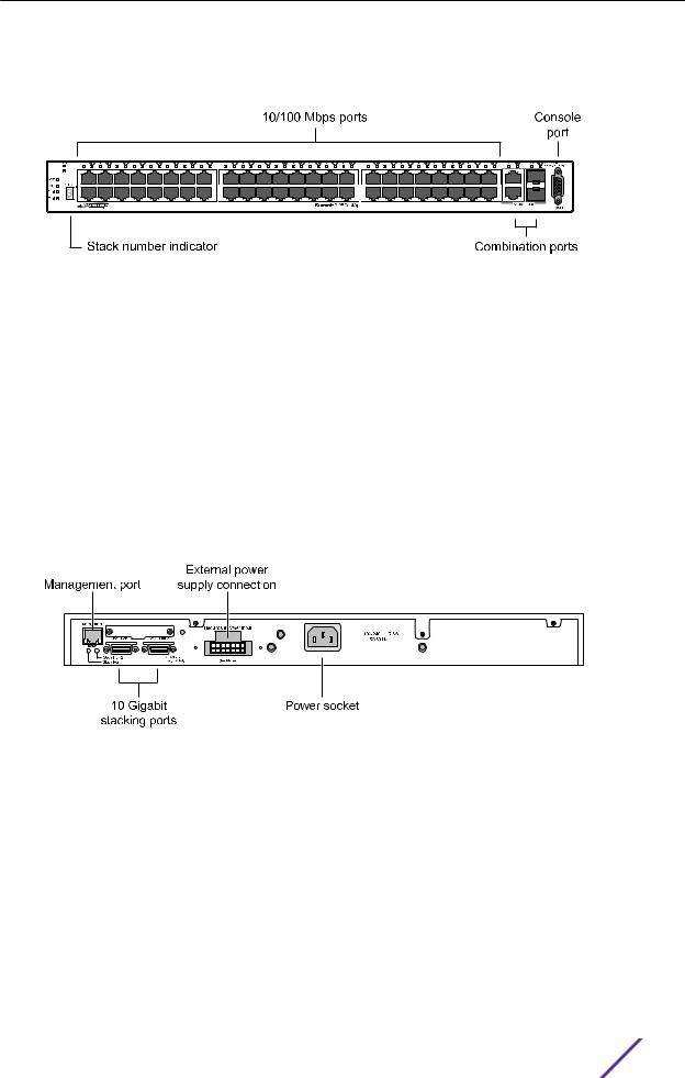
Summit X250e-48p Switch Ports and Slots
The front panel of the Summit X250e-48p switch includes:
•Forty-eight fixed autosensing 10/100BASE-T PoE ports (ports 1–48). In addition to 4.8 Gbps of highdensity copper connectivity, these ports provide a full 15.4 Watts of PoE per port when used with the EPS-600LS External Power Module.
•Two combination ports (ports 49–50) using RJ45 connectors and SFPs to provide 2 Gbps of copper or fiber connectivity.
For more information about combination ports, see Combination Ports and Failover on page 12. For information about SFPs, see the Extreme Networks Pluggable Transceivers Installation Guide.
•LEDs to indicate port status and switch operating conditions.
For a description of the LEDs and their operation, see Summit X250e Series Switch LEDs on page 29.
Summit Family Hardware Installation Guide |
27 |
Summit Switches
•Stack number indicator showing the position of this switch in a stacked configuration.
•Serial console port used to connect a terminal and perform local management.
Figure 21: Summit X250e-48p Switch Front Panel
The rear panel of the Summit X250e-48p switch (shown in Figure 22 on page 28) includes:
•Ethernet management port with associated LEDs.
•Two high-performance stacking ports with associated LEDs.
•Redundant power input connector for use with one or more EPS-600LS External Power Modules (Model No. 10913) installed in an EPS-C chassis (Model No. 10912).
The connecting redundant power supply cable is shipped with the EPS-C chassis. The PoE capability of the Summit X250e-48p switch varies depending on the number of external power modules in use. For more information, see EPS-600LS External Power Module on page 152.
•AC power input socket.
The internal AC power supply operates from 100 VAC to 240 VAC.
Figure 22: Summit X250e-48p Switch Rear Panel
Summit X250e-48p Power Supplies
The Summit X250e-48p switch is powered by both an internal power supply and an optional external redundant power supply system.
Internal Power Supply
The Summit X250e-48p internal power supply can provide 370 W of PoE power, as follows:
•In a 24-port configuration, it provides 15.4 W to each port.
•In a 48-port configuration or any combination of ports where total PoE power does not exceed 370 watts, it provides 7.7 W to each port.
Summit Family Hardware Installation Guide |
28 |

Summit Switches
If the total system demands exceed this power limit, you can specify one of the following:
•Port priorities to identify which ports should be ranked higher when allocating power
•Port disconnect precedence to specify the method of shutting off ports when not enough PoE power is available
Note
For a detailed discussion of these concepts, see the Power over Ethernet section in the
ExtremeXOS 22.3 User Guide.
External Power Supplies
The EPS-600LS External Power Module provides optional redundant power for the Summit X250e-48p switch.
Through the redundant power input connector on the rear panel, the switch can be powered by one, two, or three external power modules installed in the EPS-C External Power Supply Chassis.
The PoE capability of the Summit X250e-48p varies depending on the number of external power modules in use. The following table summarizes the PoE power behavior for the Summit X250e-48p switch based on the number of power supply modules in use.
Internal Power |
EPS-600LS (1x) |
EPS-600LS (2x) |
EPS-600LS (3x) |
External Power Supply/ |
Supply Status |
|
|
|
Chassis Failed/ |
|
|
|
|
Disconnected |
|
|
|
|
|
Internal power |
370 W of |
740 W of external |
740 W of external |
370 W of internal |
supply: |
redundant power |
power only; internal |
power only with 2:1 |
power only |
Power on |
|
power supply disabled |
redundancy; internal |
|
|
|
|
power supply disabled |
|
|
|
|
|
|
Internal power |
370 W of external |
740 W of external |
740 W of external |
No PoE power |
supply: |
power only |
power only |
power only with 2:1 |
|
Power Failure |
|
|
redundancy |
|
|
|
|
|
|
For specifications and installation instructions for the external power module, see EPS-600LS External Power Module on page 152.
Summit X250e Series Switch LEDs
The following sections describe the meanings of the LEDs on Summit X250e switches.
Summit Family Hardware Installation Guide |
29 |

Summit Switches
LEDs on the Summit X250e Series Switches
Table 6: Front Panel
Label or Type |
Color/State |
Meaning |
|
|
|
|
|
MGMT |
Blinking green (fast) |
Power-on self-test (POST) in progress |
|
|
|
|
|
|
Steady green |
POST passed. System is booting image. |
|
|
|
|
|
|
Blinking green (slow) |
Normal operation. |
|
|
|
|
|
|
Blinking amber |
Switch diagnostics are running. |
|
|
|
or |
|
|
|
System is disabled. POST failed or system overheated. |
|
|
|
|
|
|
Off |
No external power attached |
|
|
|
|
|
FAN |
Steady green |
Normal operation |
|
|
|
|
|
|
Blinking amber |
Fan failure. Switch will continue to operate unless it overheats. |
|
|
|
|
|
|
Off |
No power |
|
|
|
|
|
PSU-I |
Steady green |
Normal operation |
|
(Internal power |
|
|
|
Blinking amber |
Failure |
||
supply) |
|||
|
|
||
|
Off |
No power |
|
|
|
|
|
PSU-E |
Steady green |
Normal operation |
|
(External power |
|
|
|
Blinking amber |
Failure |
||
supply) |
|||
|
|
||
|
Off |
No external power attached |
|
|
|
|
|
Port number |
Steady green |
Link is OK. |
|
1 – 24 or 1 – 48 |
|
|
|
Blinking green |
Port is transmitting packets. |
||
|
|||
|
|
|
|
|
Off |
Link is not present, or port is disabled. |
|
|
|
|
|
Port number |
Steady green |
Link is OK. |
|
25, 26 or 49, 50 |
|
|
|
Blinking green |
Port is transmitting packets. |
||
(Shared ports) |
|||
|
|
||
|
Off |
Link is not present, or port is disabled. |
|
|
|
|
|
Stack 1, Stack 2 |
Steady green |
Link OK on the indicated stacking port. |
|
|
|
|
|
|
Blinking green |
Activity on the indicated stacking port. |
|
|
|
|
|
Stack Number |
Off |
This switch is not in stacking mode. |
|
Indicator |
|
|
|
Top half of number blinking |
This switch is the stack master. |
||
|
|||
|
|
|
|
|
Lower half of number |
This switch is the stack backup. |
|
|
blinking |
|
|
|
|
|
|
|
Number lights steadily |
This switch is a standby switch (neither the master nor the |
|
|
|
backup). |
|
|
|
|
Summit Family Hardware Installation Guide |
30 |
Loading...