


 Loading...
AP-8132 Access Point
INSTALLATION GUIDE
2 |
AP-8132 Access Point |
MOTOROLA SOLUTIONS and the Stylized M Logo are registered in the US Patent & Trademark Office. © Motorola Solutions, Inc. 2013. All rights reserved.
Installation Guide |
3 |
1.0 Introduction . . . . . . . . . . . . . . . . . . . . . . . . . . . . . . . . . . . . . . . . . . . . . . . 5
1.1 Document Conventions . . . . . . . . . . . . . . . . . . . . . . . . . . . . . . . . . . . . . 5
1.2 Warnings . . . . . . . . . . . . . . . . . . . . . . . . . . . . . . . . . . . . . . . . . . . . . . . . 6
1.3 Site Preparation . . . . . . . . . . . . . . . . . . . . . . . . . . . . . . . . . . . . . . . . . . . 6
1.4 AP-8132 Package Contents . . . . . . . . . . . . . . . . . . . . . . . . . . . . . . . . . . 6
1.4.1 Features . . . . . . . . . . . . . . . . . . . . . . . . . . . . . . . . . . . . . . . . . . . . . 7
2.0 Hardware Installation . . . . . . . . . . . . . . . . . . . . . . . . . . . . . . . . . . . . . . . 7
2.1 Installation Instructions . . . . . . . . . . . . . . . . . . . . . . . . . . . . . . . . . . . . . 8
2.2 Precautions . . . . . . . . . . . . . . . . . . . . . . . . . . . . . . . . . . . . . . . . . . . . . . . 8
2.3 Access Point Placement . . . . . . . . . . . . . . . . . . . . . . . . . . . . . . . . . . . . . 9
2.4 Power Injector System . . . . . . . . . . . . . . . . . . . . . . . . . . . . . . . . . . . . . . 9
2.5 Wall Mount Instructions . . . . . . . . . . . . . . . . . . . . . . . . . . . . . . . . . . . 11
2.5.1 Wall Mount Procedure - New Installation. . . . . . . . . . . . . . . . . . 12 2.5.1 Wall Mount Procedure - Existing Access Point Replacement . . . 13 2.6 Suspended Ceiling T-Bar Mount Installation . . . . . . . . . . . . . . . . . . . . 13 2.7 Suspended Ceiling Tile (Plenum) Installation. . . . . . . . . . . . . . . . . . . . 15 2.8 AP-8132 Antenna Options . . . . . . . . . . . . . . . . . . . . . . . . . . . . . . . . . . 18 2.9 LED Indicators. . . . . . . . . . . . . . . . . . . . . . . . . . . . . . . . . . . . . . . . . . . . 20
3.0 Basic Access Point Configuration . . . . . . . . . . . . . . . . . . . . . . . . . . . 22
4.0 Specifications . . . . . . . . . . . . . . . . . . . . . . . . . . . . . . . . . . . . . . . . . . . . . 33
4.1 Electrical Characteristics . . . . . . . . . . . . . . . . . . . . . . . . . . . . . . . . . . . 33
4.2 Physical Characteristics . . . . . . . . . . . . . . . . . . . . . . . . . . . . . . . . . . . . 33
4.3 Radio Characteristics . . . . . . . . . . . . . . . . . . . . . . . . . . . . . . . . . . . . . . 34
5.0 Regulatory Information . . . . . . . . . . . . . . . . . . . . . . . . . . . . . . . . . . . . . 35
5.1 Wireless Device Country Approvals. . . . . . . . . . . . . . . . . . . . . . . . . . . 35
5.1.1Country Selection . . . . . . . . . . . . . . . . . . . . . . . . . . . . . . . . . . . . . 35
5.1.2 Frequency of Operation - FCC and IC . . . . . . . . . . . . . . . . . . . . . . 35
5.2 Health and Safety Precautions. . . . . . . . . . . . . . . . . . . . . . . . . . . . . . . 36
5.2.1 Warnings for Use of Wireless Devices . . . . . . . . . . . . . . . . . . . . 36
4 |
AP-8132 Access Point |
5.2.2 Potentailly Hazardous Atmospheres - Fixed Installatons . . . . . .36
5.2.3 Safety in Hospitals . . . . . . . . . . . . . . . . . . . . . . . . . . . . . . . . . . . .36
5.3 RF Exposure Giudelines . . . . . . . . . . . . . . . . . . . . . . . . . . . . . . . . . . . .37
5.3.1 Safety Information . . . . . . . . . . . . . . . . . . . . . . . . . . . . . . . . . . . .37
5.4 International . . . . . . . . . . . . . . . . . . . . . . . . . . . . . . . . . . . . . . . . . . . . .37
5.5 EU . . . . . . . . . . . . . . . . . . . . . . . . . . . . . . . . . . . . . . . . . . . . . . . . . . . . .37
5.6 US and Canada . . . . . . . . . . . . . . . . . . . . . . . . . . . . . . . . . . . . . . . . . . .37
5.7 Power Suppply . . . . . . . . . . . . . . . . . . . . . . . . . . . . . . . . . . . . . . . . . . .37
5.8 Radio Frequency Interference Requirements - FCC . . . . . . . . . . . . . . .38
5.8.1 Radio Transmitters (Part 15) . . . . . . . . . . . . . . . . . . . . . . . . . . . .38
5.9 Radio Frequency Interference Requirements - Canada . . . . . . . . . . . .38
5.9.1 Radio Transmitters . . . . . . . . . . . . . . . . . . . . . . . . . . . . . . . . . . . .38
5.10 CE Marking and European Economic Area . . . . . . . . . . . . . . . . . . . . .39
5.11 Statement of Compliance . . . . . . . . . . . . . . . . . . . . . . . . . . . . . . . . . .39
5.12 Waste Electrical and Electronic Equipment (WEEE) . . . . . . . . . . . . .42
5.13 Turkish WEEE Statement of Compliance . . . . . . . . . . . . . . . . . . . . . .43
6.0 Motorola Solutions Support Center . . . . . . . . . . . . . . . . . . . . . . . . . . .44 8.0 AP-8132 Access Point China ROHS Compliance . . . . . . . . . . . . . . .45

Installation Guide |
5 |
1 Introduction
The AP-8132 is a premium, Enterprise class, Access Point positioned at the top of Motorola Solutions’ Access Point product line. The AP-8132 is a plenum rated, 3x3:3 802.11n Access Point utilizing two 802.11abgn radios.
An AP-8132 model Access Point uses WiNG 5 software as its onboard operating system. The Access Point’s unique WiNG 5 software enables the Access Point to function as either a Virtual Controller AP capable of adopting and managing up to 24 additional AP-8132 Access Points, a Standalone Access Point or a Dependent mode Access Point managed by its connected controller.
If new to Motorola Solutions Access Point technology, refer to the WiNG Access Point System Reference Guide to familiarize yourself with Access Point technology and the feature set supported by the WiNG operating system. This guide is available at http://supportcentral.motorolasolutions.com/support/product/manuals.do.
This document is written for the qualified network device installer.
1.1 Document Conventions
The following graphical alerts are used in this document to indicate notable situations:
NOTE Tips, hints, or special requirements that you should take note of.
! |
CAUTION Care is required. Disregarding a caution can result in data loss or |
equipment malfunction. |
WARNING! Indicates a condition or procedure that could result in personal injury or equipment damage.

6 |
AP-8132 Access Point |
1.2Warnings
•Read all installation instructions and site survey reports, and verify correct equipment installation before connecting the AP-8132 model Access Point.
•Remove jewelry and watches before installing this equipment.
•Verify any device connected to this unit is properly wired and grounded.
•Verify there is adequate ventilation around the device, and that ambient temperatures meet equipment operation specifications.
1.3Site Preparation
•Consult your site survey and network analysis reports to determine specific equipment placement, power drops, and so on.
•Assign installation responsibility to the appropriate personnel.
•Identify and document where all installed components are located.
•Ensure adequate, dust-free ventilation to all installed equipment.
•Identify and prepare Ethernet and console port connections.
•Verify cable lengths are within the maximum allowable distances for optimal signal transmission.
1.4AP-8132 Package Contents
An AP-8132 Access Point is available in external antenna models only. An AP-8132 ships with the following:
•AP-8132 access point
•AP-8132 Installation Guide (This Guide)
•Wall mount screw and anchor kit
•Accessories bag (LED light pipe for above the ceiling installations)
NOTE An AP-8132 Access Point can ship with a separately ordered protective cover (facade) containing a 6-element MIMO antenna (Part No. ML-2452-PTA6M6-1). When attached, LEDs continue to illuminate through the cover (similar to the illustration on the next page). A version of the facade is also available without the MIMO antenna. This cover (Part No. 21-8132FAC-01) functions strictly as a protective cover for the Access Point and provides no operational functionality.

Installation Guide |
7 |
1.4.1 Features
An AP-8132 access point minimally supports the following feature set:
•3 RJ-45 connectors (GE1/POE, GE2 and Console)
•LED indicators
•Slots for wall mounting
•Lock port for Kensington® style security lock
•Two custom dual band radios
•Features for snap-on module support through the Access Point’s USB interface
•3x3 MIMO, 3 spatial streams
The AP-8132 access point has two RJ-45 connectors supporting 10/100/1000 Ethernet. GE1/POE accepts 802.3at or 802.3af compliant power from an external source
NOTE When operating in a Gigabit Ethernet environment, CAT-5e or CAT-6 cable is recommended for Gigabit operation.

8 |
AP-8132 Access Point |
2 Hardware Installation
2.1 Installation Instructions
An AP-8132 Access Point mounts either on a wall (with M4 x 25 pan head screws and wall anchor - or equivalent) or on a suspended ceiling T-bar.
Once the AP-8132 is installed with facade and cabled, the cables (Ethernet and module connections) should not be visible when looking directly at the unit (ceiling and wall mounts).
To prepare for the installation:
1.Match the model number on the purchase order with the model numbers in the packing list and on the case of the Access Point.
2.Verify the contents of the box include the intended AP-8132 Access Point, and the included hardware matches the package contents (see AP-8132 Package Contents on page 6.
Part Number |
|
Description |
|
|
|
AP-8132-66040-US |
802.11n |
3x3:3 Access Point dual radio US version |
|
|
|
AP-8132-66040-WR |
802.11n |
3x3:3 Access Point dual radio non-US (rest of world) |
version |
|
|
|
|
|
|
|
|
AP-8132-66040-EU |
802.11n |
3x3:3 Access Point dual radio European version |
|
|
|
3.Review site survey and network analysis reports to determine the location and mounting position for the AP-8132 Access Point.
4.Connect a CAT-5 or better Ethernet cable to a compatible 802.3at or 802.3af power source and run the cable to the installation site. Ensure there is sufficient slack on the cable to perform the installation steps.
NOTE When operating in a Gigabit Ethernet environment, CAT-5e or CAT-6 cable is recommended for Gigabit operation.
2.2 Precautions
Before installing an AP-8132 model Access Point, verify the following:
•Your using the correctly rated power solution for the AP-8132 (either the AP-PSBIAS-2P3-ATR power injector or the PWRS-14000-247R external power supply)
•Motorola Solutions recommends you do not to install the AP-8132 in wet or dusty areas.
•Verify the environment has a continuous temperature range between 0° C to 50° C.

Installation Guide |
9 |
2.3 Access Point Placement
For optimal performance, install the Access Point away from transformers, heavy-duty motors, fluorescent lights, microwave ovens, refrigerators and other industrial equipment. Signal loss can occur when metal, concrete, walls or floors block transmission. Install the Access Point in an open area or add Access Points as needed to improve coverage.
Antenna coverage is analogous to lighting. Users might find an area lit from far away to be not bright enough. An area lit sharply might minimize coverage and create dark areas. Uniform antenna placement in an area (like even placement of a light bulb) provides even, efficient coverage.
Place the Access Point using the following guidelines:
•Install the Access Point at an ideal height of 10 feet from the ground.
•Orient the Access Point antennas vertically for best reception (applies to external antenna models only).
To maximize the Access Point’s radio coverage area, Motorola Solutions recommends conducting a site survey to define and document radio interference obstacles before installing the Access Point.
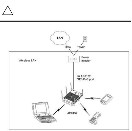
2.4 Power Injector System
An AP-8132 model Access Point can receive power via an Ethernet cable connected to the GE1/POE (LAN) port.
When users purchase a WLAN solution, they often need to place Access Points in obscure locations. In the past, a dedicated power source was required for each Access Point in addition to the Ethernet infrastructure. This often required an electrical contractor to install power drops at each Access Point location. The Power Injector merges power and Ethernet into one cable, reducing the burden of installation and allowing optimal Access Point placement in respect to the intended coverage area.
! |
CAUTION Using a non-compliant injector, or an injector supporting legacy modes |
will not allow the AP-8132 to function at optimum performance levels. |
|
|
|
|
|
|
|
|
|
CAUTION Do not plug in the AP-PSBIAS-2P3-ATR Power Injector into the Access ! Point’s Console port. Connecting the Power Injector into the console
port can damage the port and void the AP-8132’s product warranty.
The AP-8132’s supported Power Injector (Part No. AP-PSBIAS-2P3-ATR) is a high power POE Injector delivering up to 30 watts. The Access Point can only use a Power Injector when connecting the unit to the Access Point’s GE1/POE port. The Power Injector is separately ordered and not shipped with an existing AP SKU.
The Motorola Access Point Power Supply (Part No. PWRS-14000-247R) is not included with the Access Point and is orderable separately as an accessory. If the Access Point is provided both POE power and PWRS-14000-247R power concurrently, the Access Point will source power from the PWRS-14000-247R supply only. Disconnecting AC power from the PWRS-14000-247R, causes the Access Point to re-boot before sourcing power from the POE power injector. If the AP is operating using injector supplied power, the AP will not automatically reboot if an AC adapter
10 |
AP-8132 Access Point |
is connected. The Access Point continues to operate with power supplied from the AC adapter without change to the Access Point operating configuration. If using AC adapter supplied power and a change to the AP’s operating configuration is warranted, the Access Point needs to be manually rebooted by the customer.
CAUTION The Access Point supports any standards-based compliant power source (including non-Motorola Solutions power sources). However,
! using the wrong solution (including a POE system used on a legacy Motorola Solutions Access Point) could either limit functionality or severely damage the Access Point and void the product warranty.
A separate Power Injector is required for each AP-8132 Access Point comprising the network.
The Power Injector can be installed free standing, on an even horizontal surface or wall mounted using the power injector’s wall mounting key holes. The following guidelines should be adhered to before cabling the Power Injector to an Ethernet source and an Access Point:
•Do not block or cover airflow to the Power Injector.
•Keep the Power Injector away from excessive heat, humidity, vibration and dust.
Installation Guide |
11 |
•The Power Injector isn’t a repeater, and does not amplify the Ethernet signal. For optimal performance, ensure the Power Injector is placed as close as possible to the data port.
CAUTION To avoid problematic performance and restarts, disable POE from a ! wired switch port connected to an Access Point if mid-span power
sourcing equipment (PSE) is used between the two, regardless of the manufacturer of the switch.
To install the Power Injector to an Ethernet data source and an Access Point:
CAUTION Ensure AC power is supplied to the Power Injector using an AC cable ! with an appropriate ground connection approved for the country of
operation.
1.Connect the Power Injector to an AC outlet (110VAC to 220VAC).
2.Connect an RJ-45 Ethernet cable between the network data supply (host) and the Power Injector Data In connector.
3.Connect an RJ-45 Ethernet cable between the Power Injector Data & Power Out connector and the Access Point’s GE1/POE port.
CAUTION Cabling a Power Injector to the WAN port (GE2 port) renders the AP ! non-operational. Only use a AP-PSBIAS-2P3-ATR Power Injector with
the Access Point’s GE1/POE (LAN) port.
Ensure the cable length from the Ethernet source (host) to the Power Injector and Access Point does not exceed 100 meters (333 ft).
The Power Injector has no On/Off power switch. The Injector receives power and is ready for device connection and operation as soon as AC power is applied. Refer to the Installation Guide shipped with the Power Injector for a description of the device’s LEDs.
2.5 Wall Mount Instructions
A wall mount deployment requires hanging the AP-8132 access point along its width or length using two of three slots on the bottom of the unit. The AP-8132 can be mounted on to any plaster, wood or cement wall surface using the provided wall anchors.
The hardware required to install the AP-8132 on a wall consists of:
•Two wide-shoulder Phillips pan head self-tapping screws (M3.5 x 0.6 x 23 mm)
•Two wall anchors
•Security cable (optional)

12 |
AP-8132 Access Point |
Optional customer provided installation tools include:
•Security cable
•Philips head screw driver, or drill and drill bit
2.5.1Wall Mount Procedure - New Installation
This section describes a new AP-8132 installation with no previous Access Point existing on the intended wall surface.
1.Place the Access Point against the wall, ensuring the Access Point’s Motorola Solutions “bat wings” logo is in the correct orientation.
2.Mark the screw hole locations 152mm (6 in.) apart on the Access Point’s long axis or 40mm (1.57 in.) apart on the Access Point’s short axis, depending on the intended deployment orientation of the unit.
3.At each point, drill a hole in the wall and insert the anchor.
NOTE When pre-drilling a hole the recommended hole size is 4mm (0.16in.).
4.Place the Access Point on the anchor. Insert screws through into the anchor.
5.If required, install and attach a Kensington security cable (customer supplied) to the unit’s lock port.
6.Cable the Access Point using either the Power Injector solution (AP-PSBIAS-2P3-ATR) or the approved AP-8132 power supply (PWRS-14000-247R).
For Motorola Power Injector installations:
a.Connect a RJ-45 CAT5e (or CAT6) Ethernet cable between the network data supply (host) and the Power Injector Data In connector.
b.Connect a RJ-45 CAT5e (or CAT6) Ethernet cable between the Power Injector Data & Power Out connector and the Access Point’s GE1/POE port.
c.Ensure the cable length from the Ethernet source (host) to the Power Injector and
Access Point does not exceed 100 meters (333 ft). The Power Injector has no On/Off power switch. The Power Injector receives power as soon as AC power is applied.
For standard power adapter (non Power Injector) and line cord installations:
a.Connect a RJ-45 Ethernet cable between the network data supply (host) and the Access Point’s GE1/POE or GE2 port.
b.Verify the power adapter is correctly rated according to the country of operation.
c.Connect the power supply line cord to the power adapter.
d.Attach the power adapter cable into the power connector on the Access Point.
e.Attach the power supply line cord to a power supply.

Installation Guide |
13 |
7.Attach supported 2.4 GHz or 5 GHz antennas to the connectors. For more information on supported AP-8132 antennas, see AP-8132 Antenna Options on page 18.
8.Verify the Access Point is receiving power by observing the LEDs are lit or flashing. For more information on AP-8132 LED behavior, see LED Indicators on page 20.
9.The Access Point is ready to configure.
CAUTION If not using an AP-PSBIAS-2P3-ATR model power injector, ensure only the AP-8132’s designated power supply (PWRS-14000-247R) is used
! to supply power to the Access Point. Using an incorrectly rated power supply could damage the Access Point and void the product warranty. Do not actually connect to the power source until the cabling portion of the installation is complete.
2.5.2 Wall Mount Procedure - Existing Access Point Replacement
An existing AP-7131 or AP-7131N Series Access Point, installed on a wall (plenum installation), can be replaced by an AP-8132. Simply remove the existing AP-7131 or AP-7131N from its mounting screws, leave the mounting hardware in place and install the new AP-8132 directly on to the existing mounting hardware. The cabling procedure for such a replacement is as described in the previous section.
2.6 Suspended Ceiling T-Bar Mount Instructions
Ceiling mount requires holding the AP-8132 up against a T-bar of a suspended ceiling grid and twisting the unit on to the T-bar. If deploying the AP-8132 on a sculpted ceiling T-Bar, the Access Point mounting kit (Part No. KT-135628-01) can optionally be used as well.
1.If required, install and attach a Kensington security cable (customer provided) to the unit’s lock port.
2.Using only the mounting bracket from the mounting kit, rotate and click the mounting bracket into the mounting slots on the AP-8132.
3.Attach the antennas to their correct connectors. For more information on supported AP-8132 antennas, see AP-8132 Antenna Options on page 18.
4.Cable the Access Point using either the Power Injector solution (AP-PSBIAS-2P3-ATR) or the approved AP-8132 power supply (PWRS-14000-247R).
For Motorola Power Injector installations:
a.Connect a RJ-45 CAT5e (or CAT6) Ethernet cable between the network data supply (host) and the Power Injector Data In connector.
b.Connect a RJ-45 CAT5e (or CAT6) Ethernet cable between the Power Injector Data & Power Out connector and the Access Point’s GE1/POE port.
c.Ensure the cable length from the Ethernet source (host) to the Power Injector and
Access Point does not exceed 100 meters (333 ft). The Power Injector has no On/Off power switch. The Power Injector receives power as soon as AC power is applied.

14 |
AP-8132 Access Point |
For standard power adapter (non Power Injector) and line cord installations:
a.Connect a RJ-45 Ethernet cable between the network data supply (host) and the Access Point’s GE1/POE or GE2 port.
b.Verify the power adapter is correctly rated according the country of operation.
c.Connect the power supply line cord to the power adapter.
d.Attach the power adapter cable into the power connector on the Access Point.
e.Attach the power supply line cord to a power supply.
CAUTION If not using an AP-PSBIAS-2P3-ATR model power injector, ensure only the AP-8132’s designated power supply (PWRS-14000-247R) is used
! to supply power to the Access Point. Using an incorrectly rated power supply could damage the Access Point and void the product warranty. Do not actually connect to the power source until the cabling portion of the installation is complete.
5.Verify the unit has power by observing the LEDs. For more information on AP-8132 LED behavior, see
LED Indicators on page 20.
6.Align the bottom of the ceiling T-bar with the back of the Access Point.
7.Orient the Access Point chassis by its length and the length of the ceiling T-bar.
8.Rotate the Access Point chassis 45 degrees clockwise.
9.Push the back of the Access Point chassis on to the bottom of the ceiling T-bar.
10.Rotate the Access Point chassis 45 degrees counter-clockwise. The clips click as they fasten to the T-bar.
11. The Access Point is ready to configure.

Installation Guide |
15 |
2.7 Suspended Ceiling Tile (Plenum) Mount Instructions
An above the ceiling installation requires placing the Access Point above a suspended ceiling and installing the provided light pipe under the ceiling tile for viewing the rear panel status LEDs of the unit. An above the ceiling installation enables installations compliant with drop ceilings, suspended ceilings and industry standard tiles from
.625 to .75 inches thick.
The mounting hardware required to install the Access Point above a ceiling consists of:
•Light pipe
•Badge for light pipe
•Safety wire (strongly recommended)
•Security cable (optional)
NOTE Notes or warnings about suspended ceiling mounts apply to all installations where the unit is placed on suspended ceiling tile.
CAUTION Motorola does not recommend mounting the Access Point directly to any suspended ceiling tile with a thickness less than 12.7mm (0.5in.) or a suspended ceiling tile with an unsupported span greater than
! 660mm (26in.). Motorola strongly recommends fitting the Access Point with a safety wire suitable for supporting the weight of the device. The safety wire should be a standard ceiling suspension cable or equivalent steel wire between 1.59mm (.062in.) and 2.5mm (.10in.) in diameter.
To install the Access Point above a ceiling:
NOTE Remove the Access Point’s facade and antennas before installing in an above the ceiling orientation. The Access Point is not certified for an above the ceiling installation with its accessories installed.
1.If possible, remove the ceiling tile from its frame and place it, finish side down, on a work surface.
2.If required, install a safety wire, between 1.5mm (.06in.) and 2.5mm (.10in.) in diameter, in the ceiling space.
3.If required, install and attach a security cable to the Access Point’s lock port.
4.Mark a point on the finished side of the tile where the light pipe is to be located.
5.Create a light pipe path hole in the target position on the ceiling tile.
Loading...