

Page 1
Ethernet and
Fibre Channel Application
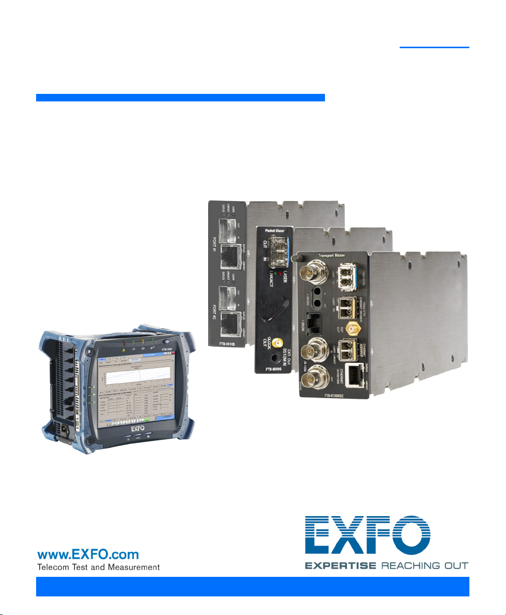
FTB-8500 Series and FTB-8120NGE/8130NGE for FTB-500
User Guide
Page 2

Copyright © 2003–2012 EXFO Inc. All rights reserved. No part of this
publication may be reproduced, stored in a retrieval system or transmitted
in any form, be it electronically, mechanically, or by any other means such
as photocopying, recording or otherwise, without the prior written
permission of EXFO Inc. (EXFO).
Information provided by EXFO is believed to be accurate and reliable.
However, no responsibility is assumed by EXFO for its use nor for any
infringements of patents or other rights of third parties that may result from
its use. No license is granted by implication or otherwise under any patent
rights of EXFO.
EXFO’s Commerce And Government Entities (CAGE) code under the North
Atlantic Treaty Organization (NATO) is 0L8C3.
The information contained in this publication is subject to change without
notice.
Trademarks
EXFO’s trademarks have been identified as such. However, the presence
or absence of such identification does not affect the legal status of any
trademark.
Units of Measurement
Units of measurement in this publication conform to SI standards and
practices.
January 23, 2012
Version number: 7.0.1
ii FTB-8500 Series and FTB-8120NGE/8130NGE
Page 3

Contents
Certification Information ....................................................................................................... ix
1 Introducing the Ethernet and Fibre Channel Application ......................... 1
Conventions ............................................................................................................................3
2 Safety Information ....................................................................................... 5
Laser Safety Warnings .............................................................................................................5
Installation Instruction Warnings ............................................................................................6
3 Getting Started ............................................................................................ 9
ToolBox Installation .................................................................................................................9
Inserting and Removing Test Modules ....................................................................................9
Turning the Unit On ................................................................................................................9
4 Physical Interfaces and LEDs ..................................................................... 11
FTB-8510B Model .................................................................................................................11
FTB-8510G Model .................................................................................................................15
FTB-8525 and FTB-8535 Models ...........................................................................................17
FTB-8120NGE and FTB-8130NGE Models ..............................................................................24
5 Introducing the Smart User Interface ....................................................... 33
Starting the Module Application ...........................................................................................33
Main Window .......................................................................................................................35
Global Test Status and Controls ............................................................................................42
Favorites ...............................................................................................................................46
Test Report Generation .........................................................................................................48
Typical Tab Elements .............................................................................................................52
Tab Configuration .................................................................................................................55
Keyboard Usage ....................................................................................................................59
Ethernet and Fibre Channel Application iii
Page 4

6 Creating and Starting a Test Case ..............................................................65
Introducing the Test Setup ....................................................................................................66
Test Case Availability .............................................................................................................70
EtherSAM (Y.1564) Test Case .................................................................................................71
Ethernet EtherSAM (Y.1564) and RFC 2544 Dual Test Set Test Cases .....................................78
Ethernet RFC 2544 Test Case .................................................................................................87
Ethernet BERT Test Case ........................................................................................................93
Ethernet Frame Analyzer Test Case ......................................................................................100
Ethernet Smart Loopback Test Case ....................................................................................107
Ethernet TCP Throughput Test Case ....................................................................................111
Fibre Channel BERT Test Case ..............................................................................................114
7 Summary Tabs ...........................................................................................119
Test Summary .....................................................................................................................119
Alarm Summary ..................................................................................................................126
Test Logger .........................................................................................................................129
8 Port Tabs ....................................................................................................131
Electrical TX ........................................................................................................................132
Electrical RX ........................................................................................................................134
Optical TX ...........................................................................................................................136
Optical RX ...........................................................................................................................138
Interface Setup (Ethernet) ...................................................................................................140
Interface Setup (Fibre Channel) ..........................................................................................144
Network ..............................................................................................................................148
Advanced Auto-Neg. TX .....................................................................................................152
Advanced Auto-Neg. RX .....................................................................................................157
iv FTB-8500 Series and FTB-8120NGE/8130NGE
Page 5

9 Traffic Analyzer Tabs ................................................................................ 159
Ethernet TX .........................................................................................................................160
Ethernet RX ........................................................................................................................163
Ethernet Statistics ...............................................................................................................166
PBB-TE ................................................................................................................................168
Higher Layers ......................................................................................................................170
Flow Control .......................................................................................................................172
Traffic Filters .......................................................................................................................175
Traffic Filter Configuration ..................................................................................................180
Traffic Filter Stats ................................................................................................................182
Capture ...............................................................................................................................184
Graph .................................................................................................................................189
FC TX ..................................................................................................................................190
FC RX ..................................................................................................................................193
FC Latency ..........................................................................................................................195
FC Statistics ........................................................................................................................197
10 Stream Generation Tabs .......................................................................... 199
Overview .............................................................................................................................200
Stream Configuration .........................................................................................................207
PBB-TE ................................................................................................................................216
MAC ...................................................................................................................................218
MPLS ...................................................................................................................................221
IP/UDP/TCP ..........................................................................................................................223
Payload ...............................................................................................................................226
Frame Configuration (Fibre Channel) ..................................................................................227
11 Stream Analyzer Tabs ............................................................................... 237
Overview .............................................................................................................................237
Stream ................................................................................................................................239
12 WIS Tabs .................................................................................................... 241
WIS TX ................................................................................................................................241
WIS RX ................................................................................................................................245
WIS OH RX ..........................................................................................................................248
13 Pattern Tabs .............................................................................................. 251
Pattern TX ...........................................................................................................................252
Pattern RX ...........................................................................................................................255
Ethernet and Fibre Channel Application v
Page 6

14 IPTV Tabs ....................................................................................................257
IPTV Testing with the FTB-8510B .........................................................................................258
Discovery ............................................................................................................................260
Overview .............................................................................................................................264
MDI/TR 101 290 ..................................................................................................................279
IGMP ...................................................................................................................................286
Stream Information ............................................................................................................292
15 RFC 2544 Tabs ............................................................................................297
Global Configuration ..........................................................................................................298
Throughput ........................................................................................................................302
Back-to-Back .......................................................................................................................307
Frame Loss ..........................................................................................................................311
Latency ...............................................................................................................................315
Graph .................................................................................................................................320
16 EtherSAM Tabs ..........................................................................................323
Overview (Configuration) ....................................................................................................324
Services (Configuration) ......................................................................................................329
Ramp (Configuration) .........................................................................................................335
Burst (Configuration) ..........................................................................................................337
Overview (Results) ..............................................................................................................340
Service Configuration Test (Results) ....................................................................................345
Service Performance Test (Results) ......................................................................................348
17 TCP Throughput Tabs ................................................................................351
TCP Throughput Configuration ...........................................................................................351
TCP Throughput Analysis ....................................................................................................355
18 Advanced Tab ............................................................................................357
Service Disruption Time (SDT) .............................................................................................357
19 Common Tab .............................................................................................361
Performance Monitoring (PM) ............................................................................................361
20 System Tabs ...............................................................................................365
Preferences .........................................................................................................................366
Default/Ethernet Test Preferences .......................................................................................368
IPv6 Test Preferences ...........................................................................................................371
FC Test Preferences .............................................................................................................374
Module Information ...........................................................................................................376
Software Options ................................................................................................................378
Clock Synchronization ........................................................................................................383
Remote Control ..................................................................................................................388
vi FTB-8500 Series and FTB-8120NGE/8130NGE
Page 7

21 Tools Tabs .................................................................................................. 389
Script ..................................................................................................................................390
Ping Configuration .............................................................................................................394
Ping Results ........................................................................................................................396
Trace Route Configuration ..................................................................................................399
Trace Route Results .............................................................................................................400
ENIU Configuration .............................................................................................................403
ADC Configuration .............................................................................................................404
802.3ah Configuration .......................................................................................................408
802.3ah Statistics ...............................................................................................................410
802.3ah Events ...................................................................................................................413
Traffic Scan .........................................................................................................................415
22 Expert Mode Tabs ..................................................................................... 423
Expert Mode (RFC 2544) .....................................................................................................424
Throughput (RFC 2544) ......................................................................................................426
Back-to-Back (RFC 2544) .....................................................................................................428
Frame Loss (RFC 2544) ........................................................................................................430
Latency (RFC 2544) .............................................................................................................432
Expert Mode (BERT) ............................................................................................................434
Port (BERT) ..........................................................................................................................435
Ethernet (BERT) ...................................................................................................................437
Pattern (BERT) .....................................................................................................................439
23 Automatic Power Failure Recovery ......................................................... 441
24 Maintenance ............................................................................................. 443
Recalibrating the Unit .........................................................................................................444
Recycling and Disposal (Applies to European Union Only) ..................................................444
25 Troubleshooting ....................................................................................... 445
Solving Common Problems .................................................................................................445
Contacting the Technical Support Group ............................................................................446
Transportation ....................................................................................................................446
26 Warranty ................................................................................................... 447
General Information ...........................................................................................................447
Liability ...............................................................................................................................448
Exclusions ...........................................................................................................................449
Certification ........................................................................................................................449
Service and Repairs .............................................................................................................450
EXFO Service Centers Worldwide ........................................................................................451
Ethernet and Fibre Channel Application vii
Page 8

A Specifications ............................................................................................453
Ethernet Optical Interfaces .................................................................................................453
Fibre Channel Interfaces .....................................................................................................456
Ethernet Electrical Interfaces ..............................................................................................458
Synchronization Interfaces ..................................................................................................461
B Glossary .....................................................................................................463
Acronym List .......................................................................................................................463
VLAN/B-VLAN ......................................................................................................................476
MPLS Labels ........................................................................................................................477
Path Signal Label (C2 byte) .................................................................................................478
C Pop-Up Windows .......................................................................................479
VLAN Configuration ............................................................................................................480
PBB-TE Interface configuration ...........................................................................................481
IPv4 Configuration ..............................................................................................................483
IPv6 Address Configuration ................................................................................................485
Copy Service Network Configuration ..................................................................................490
Service Profile Configuration ..............................................................................................491
Framing Configuration .......................................................................................................492
Frame Size Configuration ....................................................................................................493
Frame Format Configuration ...............................................................................................495
MAC Configuration .............................................................................................................496
MPLS Configuration ............................................................................................................497
UDP Configuration ..............................................................................................................499
TCP Configuration ..............................................................................................................499
Advanced TOS/DS ...............................................................................................................500
Ping ....................................................................................................................................502
Filter Selection ....................................................................................................................504
Truncation Calculator ..........................................................................................................505
Field Match Configuration ..................................................................................................506
Triggered Frame Details ......................................................................................................508
Data Capture Export ...........................................................................................................509
Index ...............................................................................................................511
viii FTB-8500 Series and FTB-8120NGE/8130NGE
Page 9

Certification Information
Certification Information
Federal Communications Commission (FCC) and Industry Canada (IC) Information
Electronic test and measurement equipment is exempt from FCC Part 15
compliance in the United States and from IC ICES 003 compliance in
Canada. However, EXFO Inc. (EXFO) makes reasonable efforts to ensure
compliance to the applicable standards.
The limits set by these standards are designed to provide reasonable
protection against harmful interference when the equipment is operated in
a commercial environment. This equipment generates, uses, and can
radiate radio frequency energy and, if not installed and used in accordance
with the user guide, may cause harmful interference to radio
communications. Operation of this equipment in a residential area is likely
to cause harmful interference in which case the user will be required to
correct the interference at his own expense.
European Union (CE) Information
Electronic test and measurement equipment is subject to the EMC
Directive in the European Union. The EN61326 standard prescribes both
emission and immunity requirements for laboratory, measurement, and
control equipment. This unit has been tested and found to comply with the
limits for a Class A digital device. Please refer to the CE Declaration of
Conformity on page xi.
Ethernet and Fibre Channel Application ix
Page 10

Certification Information
For continued compliance to the requirements of the EMC
Directive:
For FTB-8510G, use only double-shielded cable, type Belden 9907 or
equivalent, with a maximum length of 3m for CLOCK OUT port.
1. For FTB-8535 and FTB-8130NGE, for the BNC/EXT CLK port(s) use
double-shielded coaxial cable, type 734A or equivalent.
2. For FTB-8535 and FTB-8130NGE, for the REF OUT port use double
shielded cable, type LMR-240 ULTRAFLEX or equivalent, with a
maximum length of 3m.
Note: If the equipment described herein bears the CE symbol, the said equipment
complies with the applicable European Union Directive and Standards
mentioned in the Declaration of Conformity.
Laser
This product complies with 21 CFR 1040.10 and with EN 60825-1.
This product may employ a Class 1 or Class 1M laser SFP or XFP. The laser
classification is reproduced on the SFP/XFP.
x FTB-8500 Series and FTB-8120NGE/8130NGE
Page 11

CE Declaration of Conformity
Application of Council Directive(s): 2006/95/EC - The Low Voltage Directive
2004/108/EC - The EMC Directive
2006/66/EC - The Battery Directive
93/68/EEC - CE Marking
And their amendments
Manufacturer’s Name: EXFO Inc.
Manufacturer’s Address: 400 Godin Avenue
Quebec, Quebec
Canada, G1M 2K2
Equipment Type/Environment: Test & Measurement / Industrial
Trade Name/Model No.: Ethernet Test Module /
FTB-8510/8510B/8510G
AND
IQS-8510/8510B/8510G Packet Blazer
Standard(s) to which Conformity is Declared:
EN 61010-1:2001 Edition 2.0 Safety Requirements for Electrical Equipment for Measurement,
Control, and Laboratory Use – Part 1: General Requirements.
EN 61326-1:2006 Electrical Equipment for Measurement, Control and Laboratory
Use - EMC Requirements
EN 60825-1:2007 Edition 2.0 Safety of laser products – Part 1: Equipment classification and
requirements
EN 55022: 2006 + A1: 2007 Information technology equipment — Radio disturbance
characteristics — Limits and methods of measurement
I, the undersigned, hereby declare that the equipment specified above conforms to the above Directives and Standards.
Manufacturer
Signature:
Full Name: Stephen Bull, E. Eng
Position: Vice-President Research and
Development
Address: 400 Godin Avenue, Quebec (Quebec),
Canada, G1M 2K2
Date: February 1, 2009
DECLARATION OF CONFORMITY
Certification Information
Ethernet and Fibre Channel Application xi
Page 12
Certification Information
Application of Council Directive(s): 2006/95/EC - The Low Voltage Directive
2004/108/EC - The EMC Directive
2006/66/EC - The Battery Directive
93/68/EEC - CE Marking
And their amendments
Manufacturer’s Name: EXFO Inc.
Manufacturer’s Address: 400 Godin Avenue
Quebec, Quebec
Canada, G1M 2K2
Equipment Type/Environment: Test & Measurement / Industrial
Trade Name/Model No.: Fibre Channel and Ethernet Test Modules /
FTB-8525/8535 AND IQS-8525/8535
Packet Blazer
Standard(s) to which Conformity is Declared:
EN 61010-1:2001 Edition 2.0 Safety Requirements for Electrical Equipment for Measurement,
Control, and Laboratory Use – Part 1: General Requirements.
EN 61326-1:2006 Electrical Equipment for Measurement, Control and Laboratory
Use - EMC Requirements
EN 60825-1:2007 Edition 2.0 Safety of laser products – Part 1: Equipment classification and
requirements
EN 55022: 2006 + A1: 2007 Information technology equipment — Radio disturbance
characteristics — Limits and methods of measurement
I, the undersigned, hereby declare that the equipment specified above conforms to the above Directives and Standards.
Manufacturer
Signature:
Full Name: Stephen Bull, E. Eng
Position: Vice-President Research and
Development
Address: 400 Godin Avenue, Quebec (Quebec),
Canada, G1M 2K2
Date: February 1, 2009
DECLARATION OF CONFORMITY
xii FTB-8500 Series and FTB-8120NGE/8130NGE
Page 13

Application of Council Directive(s): 2006/95/EC - The Low Voltage Directive
2004/108/EC - The EMC Directive
2006/66/EC - The Battery Directive
93/68/EEC - CE Marking
And their amendments
Manufacturer’s Name: EXFO Inc.
Manufacturer’s Address: 400 Godin Avenue
Quebec, Quebec
Canada, G1M 2K2
Equipment Type/Environment: Test & Measurement / Industrial
Trade Name/Model No.: Next-Generation Multiservice Test Modules /
FTB-8120NGE/8130NGE
AND
IQS-8120NGE/8130NGE Power Blazer
Standard(s) to which Conformity is Declared:
EN 61010-1:2001 Edition 2.0 Safety Requirements for Electrical Equipment for Measurement,
Control, and Laboratory Use – Part 1: General Requirements.
EN 61326-1:2006 Electrical Equipment for Measurement, Control and Laboratory
Use - EMC Requirements
EN 60825-1:2007 Edition 2.0 Safety of laser products – Part 1: Equipment classification and
requirements
EN 55022: 2006 + A1: 2007 Information technology equipment — Radio disturbance
characteristics — Limits and methods of measurement
I, the undersigned, hereby declare that the equipment specified above conforms to the above Directives and Standards.
Manufacturer
Signature:
Full Name: Stephen Bull, E. Eng
Position: Vice-President Research and
Development
Address: 400 Godin Avenue, Quebec (Quebec),
Canada, G1M 2K2
Date: February 1, 2009
DECLARATION OF CONFORMITY
Certification Information
Ethernet and Fibre Channel Application xiii
Page 14

Page 15

1 Introducing the Ethernet and
Fibre Channel Application
Fully integrated test solution for performance assessment of Fibre Channel
and Ethernet transport networks.
Complete EtherSAM™ (ITU-T Y.1564) test suite. EtherSAM is the new
standard for testing Ethernet mobile backhaul and commercial
services
Throughput, back-to-back, latency and frame loss measurements as
per RFC 2544 (bidirectional)
EtherBERT™ test functionality for assessing the integrity of Ethernet
services running on WDM networks
Multiple-stream generation and analysis, allowing quality of service
(QoS) verification through VLAN and TOS/DSCP prioritization testing
MPLS and PBB-TE support for complete carrier Ethernet validation
Capability to perform BERT, RFC 2544, EtherSAM, Frame Analyzer, and
Smart Loopback tests over IPv6.
Remote control capability through the Visual Guardian Lite software
TCP throughput measurements for assessing application data
transmission over a TCP connection
IPTV testing and analysis
LAN and WAN PHY capability in a single module
Packet jitter measurement to qualify Ethernet transport networks for
transmission of delay-sensitive traffic such as video and voice-over-IP
(VoIP)
FC-0, FC-1, and FC-2 logical layer configuration for Fibre Channel port
definition, testing, and performance analysis
Round-trip latency measurement and buffer-to-buffer credit estimation
1x, 2x, 4x, and 10x Fibre Channel traffic generation and BER testing
Ethernet and Fibre Channel Application 1
Page 16

Introducing the Ethernet and Fibre Channel Application
Capability to perform full-line-rate data capture and decode.
Capability to scan incoming live traffic and auto-discover all
VLAN ID/Priority and MPLS ID/COS flows.
This user guide covers the Ethernet and Fibre Channel testing of the
following products:
Ethernet (Electrical) Fibre Channel
Model Electrical Optical
10/100/1000 Mbps 100/1000 Mbps 10 Gbps 1x/2x 4x/10x
FTB-8510B X X X
FTB-8510G X
FTB-8525 X X X
FTB-8535 X X X X X
FTB-8120NGE X X X
FTB-8130NGE X X X X X
2 FTB-8500 Series and FTB-8120NGE/8130NGE
Page 17

Introducing the Ethernet and Fibre Channel Application
Conventions
Before using the product described in this guide, you should understand
the following conventions:
WARNING
Indicates a potentially hazardous situation which, if not avoided,
could result in death or serious injury. Do not proceed unless you
understand and meet the required conditions.
CAUTION
Indicates a potentially hazardous situation which, if not avoided,
may result in minor or moderate injury. Do not proceed unless you
understand and meet the required conditions.
CAUTION
Indicates a potentially hazardous situation which, if not avoided,
may result in component damage. Do not proceed unless you
understand and meet the required conditions.
Conventions
IMPORTANT
Refers to information about this product you should not overlook.
Ethernet and Fibre Channel Application 3
Page 18

Page 19
2 Safety Information
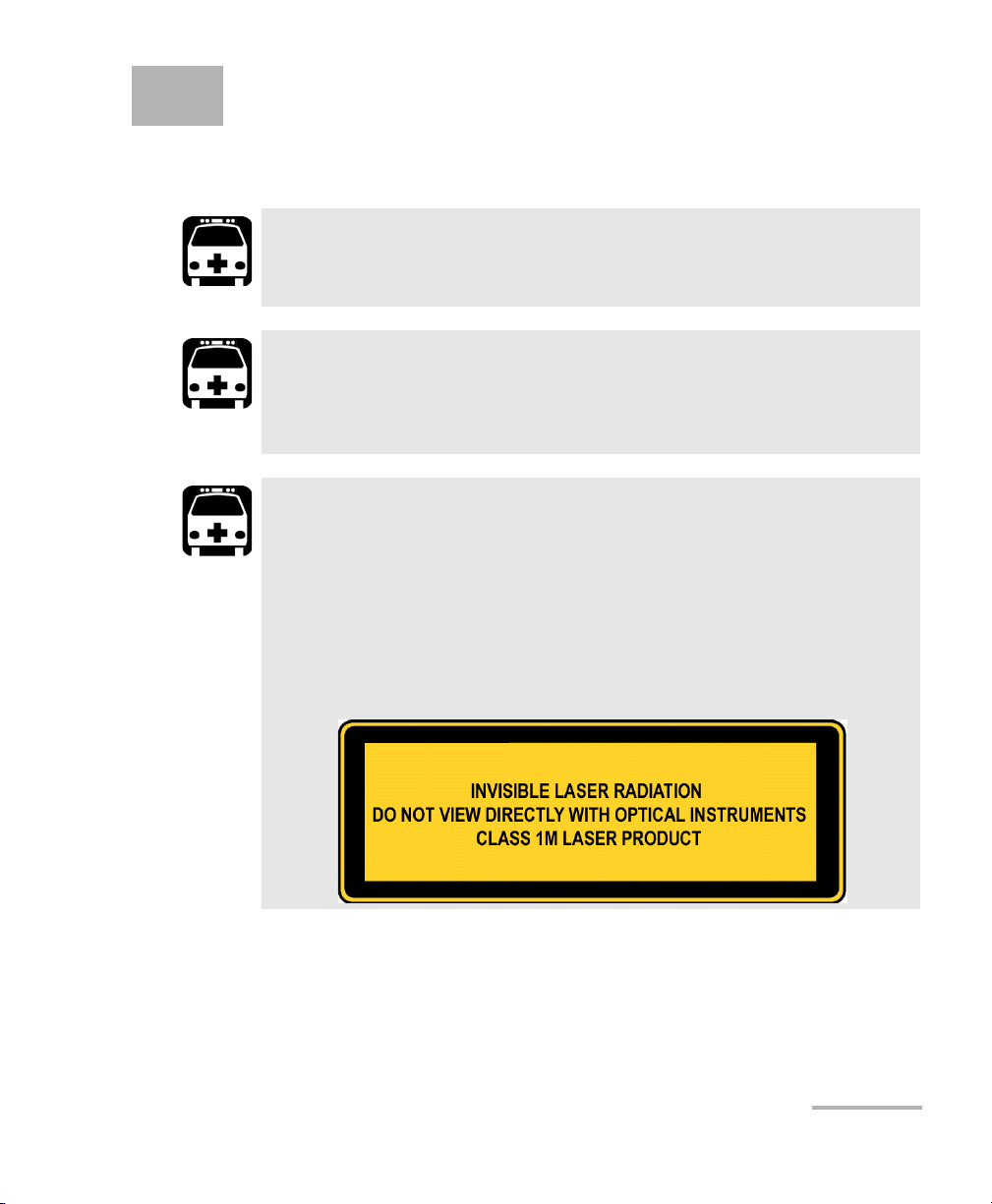
Laser Safety Warnings
WARNING
When the LASER LED is on, the FTB-8500 Series and
FTB-8120NGE/8130NGE is receiving/emitting an optical signal.
WARNING
Do not install or terminate fibers while a laser source is active.
Never look directly into a live fiber, and ensure that your eyes are
protected at all times.
WARNING
The FTB-8510B, FTB-8120NGE, and FTB-8525 may employ a Class 1M
SFP.
The FTB-8510G may employ a Class 1M laser XFP per IEC 60825-1.
The laser classification is reproduced on the XFP.
The FTB-8130NGE, and FTB-8535 may employ a Class 1M SFP and
XFP per IEC 60825-1. The laser classification is reproduced on the
XFP.
Ethernet and Fibre Channel Application 5
Page 20

Safety Information
Installation Instruction Warnings
Use of optical instruments with this product will increase eye
hazard.
Installation Instruction Warnings
This unit is for indoor use only.
All electrical interfaces are SELV (Safety Extra Low Voltage) circuitry
intended for intra-building use only.
To reduce the risk of fire, use only No. 26 AWG or larger
telecommunication line cord.
WARNING
CAUTION
CAUTION
CAUTION
No user serviceable parts are contained inside. Contact the
manufacturer regarding service of this equipment.
IMPORTANT
All wiring and installation must be in accordance with local building
and electrical codes acceptable to the authorities in the countries
where the equipment is installed and used.
6 FTB-8500 Series and FTB-8120NGE/8130NGE
Page 21

Safety Information
Installation Instruction Warnings
CAUTION
Electrostatic Discharge (ESD) Sensitive Equipment:
Plug-in modules can be damaged by static electrical discharge. To
minimize the risk of damage, dissipate static electricity by touching
a grounded unpainted metal object
before removing, inserting, or handling the module.
before connecting or disconnecting cables to/from the module.
before inserting or removing SFP/XFPs to/from the module.
IMPORTANT
All telecom (electrical) interfaces are SELV (Safety Extra Low
Voltage) circuitry for intra-building use only.
Ethernet and Fibre Channel Application 7
Page 22

Page 23
3 Getting Started
If the Ethernet and Fibre Channel Application has been purchased at the
same time as the FTB-500, the Ethernet and Fibre Channel Application
module is pre-installed with the appropriate /ToolBox software version.
ToolBox Installation
ToolBox is the baseline software and thus needs to be installed on the
FTB-500 before using the Ethernet and Fibre Channel Application module.
Note: Refer to the FTB-500 platform user guide for more information on ToolBox
installation procedure.
Inserting and Removing Test Modules
CAUTION
Never insert or remove a module while the FTB-500 is turned on.
This will result in immediate and irreparable damage to both the
module and unit.
WARNING
When the laser safety LED ( ) is flashing on the FTB-500, at least
one of your modules is emitting an optical signal. Please check all
modules, as it might not be the one you are currently using.
Note: Refer to the FTB-500 platform user guide for more information on how to
insert a module into the FTB-500 or to remove a module from the FTB-500.
Turning the Unit On
Turn on the FTB-500. Refer to the FTB-500 platform user guide for more
information.
Ethernet and Fibre Channel Application 9
Page 24

Page 25
4 Physical Interfaces and LEDs
Ethernet 10/100/1000 Mbps
Ethernet 100/1000 Mbps
FC 1x/2x
This section describes all FTB-8500 Series and FTB-8120NGE/8130NGE
models, connectors (ports), and LEDs available on each module.
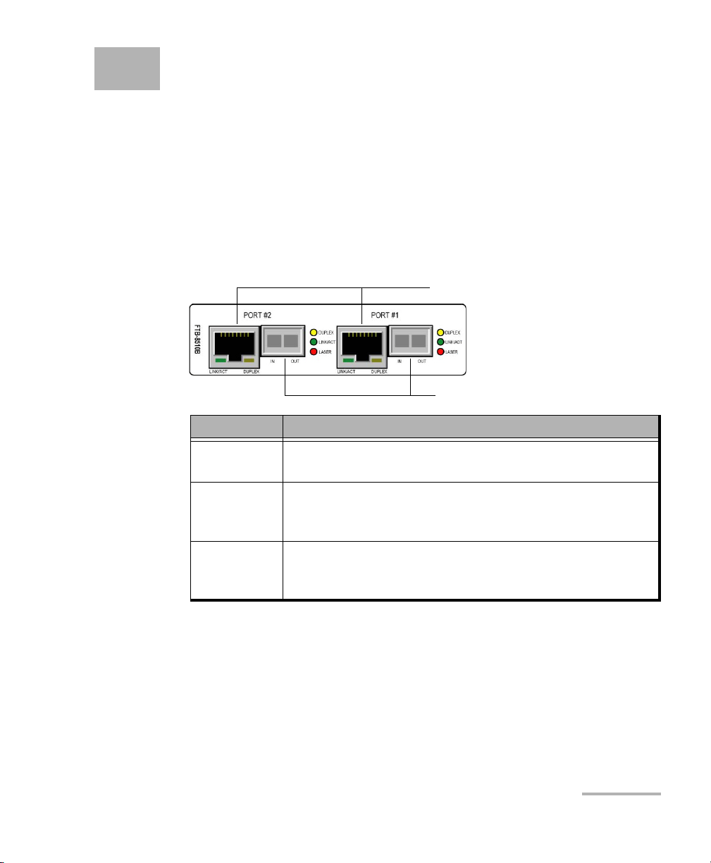
FTB-8510B Model
The FTB-8510B always comes with two electrical 10/1000/1000 Mbps
Ethernet ports and two optical ports that can be used either for 100/1000
Mbps Ethernet or 1x/2x Fibre Channel, but only the electrical 10/100 Mbps
ports are enabled on the basic model.
Model Description
FTB-8510B Ethernet and Fibre Channel Application with two electrical
10/100 Mbps Ethernet ports.
FTB-8510B-1 Ethernet and Fibre Channel Application with one electrical
10/100 Mbps Ethernet port, one electrical 10/100/1000 Mbps
Ethernet port and one 1000 Mbps Ethernet port.
FTB-8510B-2 Ethernet and Fibre Channel Application with two electrical
10/100/1000 Mbps Ethernet ports and two optical 1000
Mbps Ethernet ports.
Note: The optical 100 Mbps Ethernet ports and Fibre Channel 1x and 2x ports are
available through software options. Refer to Software Options on page 378
for more information.
Ethernet and Fibre Channel Application 11
Page 26

Physical Interfaces and LEDs
FTB-8510B Model
Electrical 10/100/1000 Mbps Ethernet
The FTB-8510B module provides two electrical ports for 10Base-T, or
100Base-TX. The FTB-8510B-1 and FTB-8510B-2 options add respectively
1000Base-T testing capability on one or both ports.
Port connector type is RJ-45 for category 5 unshielded twisted pair (UTP)
connection.
Note: Refer to Specifications on page 453 for cable specifications.
Connect the 10/100/1000 electrical signal to be tested to the port
10/100/1000 #1 or 10/100/1000 #2.
Note: Port #1 is the port enabled with the FTB-8510B-1 module for 1000Base-T
testing.
LEDs
LED Status Description
LINK/ACT
(Green)
On Ethernet link up.
Off Ethernet link down.
Flashing TX/RX activity.
DUPLEX
(Yellow)
On Full Duplex mode.
Off Half Duplex mode.
Flashing Collisions are detected.
12 FTB-8500 Series and FTB-8120NGE/8130NGE
Page 27

Physical Interfaces and LEDs
FTB-8510B Model
Optical 100/1000 Mbps Ethernet or 1x/2x Fibre Channel
The FTB-8510B-1 and FTB-8510B-2 modules provide respectively one or
two optical ports for 1000Base-X Ethernet or Fibre Channel 1x/2x testing.
The optical 100Base-FX Ethernet and Fibre Channel 1x/2x are available
through software options.
The optical ports are Small Form Factor Pluggable (SFP) slot types (Dual or
Simplex LC connector).
Insert one of the following SFP modules into the optical #1/#2 slot.
Option Description
FTB-8590 1000Base-SX / FC 1x/2x (850nm) LC connectors
optical SFP transceiver module.
FTB-8591 1000Base-LX / FC 1x/2x (1300nm) LC connectors
optical SFP transceiver module.
FTB-8592 1000Base-ZX / FC 1x/2x (1550nm) LC connectors
optical SFP transceiver module.
FTB-85910 100Base-FX (1310nm, MMF, 2Km) LC connectors
optical SFP transceiver module.
FTB-85911 100Base-LX10 (1310nm, SMF, 15Km) LC connectors
optical SFP transceiver module.
Carefully connect optical fiber cables to the SFP’s IN and OUT ports. To
ensure good signal quality, make sure that the optical fiber connector is
fully inserted into the optical connector port.
Note: Port #1 is the port enabled with the FTB-8510B-1 module for 1000Base-X
testing and when the optical 100M software option is enabled on one port
only.
Ethernet and Fibre Channel Application 13
Page 28

Physical Interfaces and LEDs
FTB-8510B Model
LEDs for Optical Ports
LED Status Description
LASER
(Red)
LINK/ACT
(Green)
DUPLEX
(Yellow)
Available
with Ethernet
interface only
On An optical signal is generated
Off No optical signal is generated
On Link up.
Off Link down.
Flashing TX/RX activity.
On Full Duplex mode.
Off Half Duplex mode, or when using
100Base-X or Fibre Channel interface.
Flashing Collisions are detected in half duplex mode.
14 FTB-8500 Series and FTB-8120NGE/8130NGE
Page 29
Physical Interfaces and LEDs
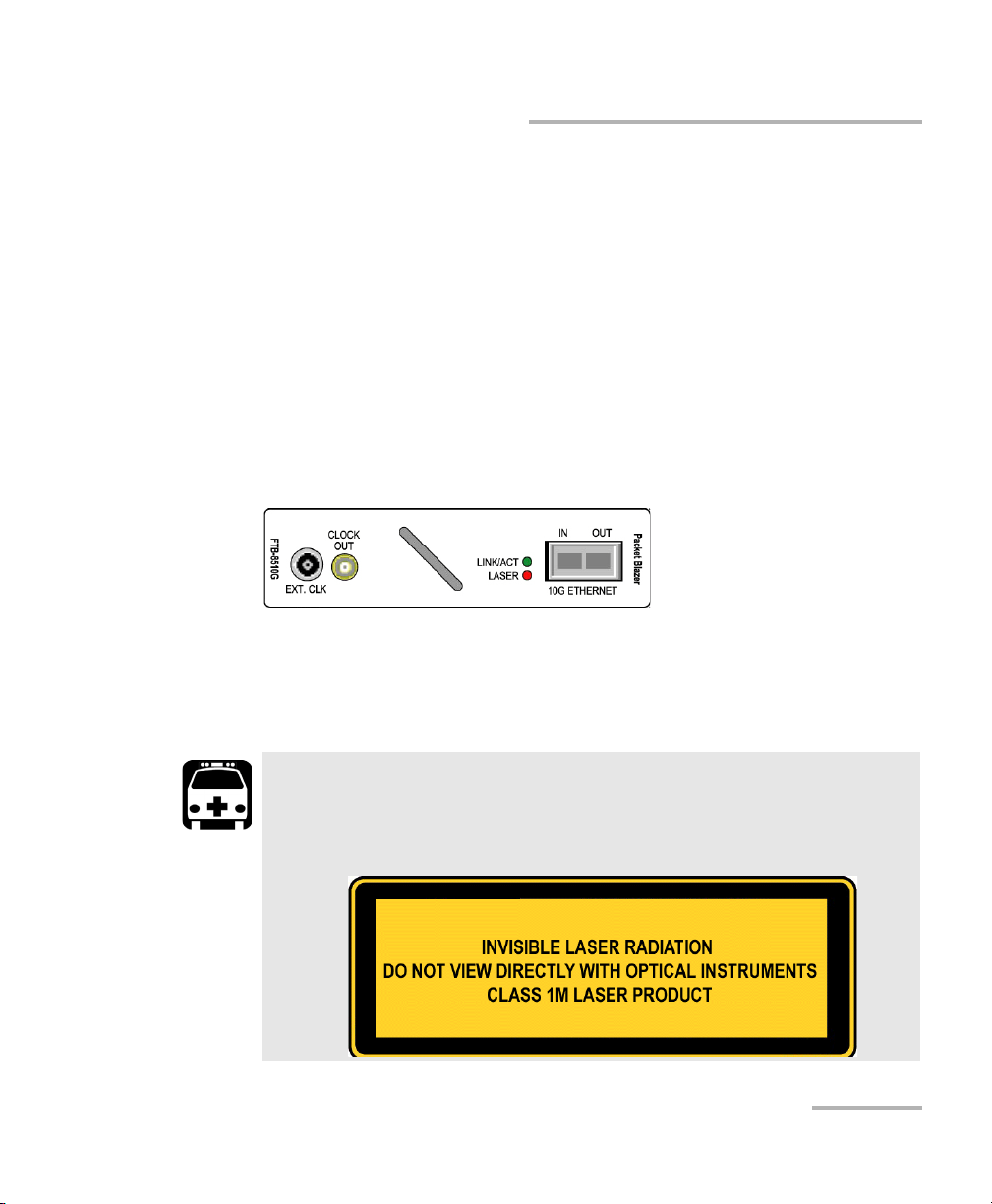
FTB-8510G Model
FTB-8510G Model
FTB-8510G-LAN: One 10 Gigabit Ethernet LAN PHY (10.3125 Gbps) port
(LC connector type).
FTB-8510G-WAN: One 10 Gigabit Ethernet WAN PHY (9.953 Gbps) port (LC
connector type).
FTB-8510G-LAN/WAN: One 10 Gigabit Ethernet LAN/WAN PHY (10.3125 /
9.953 Gbps) port (LC connector type).
FTB-8585: Software option converting an FTB-8510G-LAN or
FTB-8510G-WAN model to an FTB-8510G-LAN/WAN model.
The FTB-8510G provides an optical port labelled 10G ETHERNET, for
10 Gigabit Ethernet LAN/WAN testing capability.
Insert one of the following XFP optical transceiver into the 10G ETHERNET
slot.
WARNING
This product may employ a Class 1 or Class 1M laser XFP per IEC
60825-1. The laser classification is reproduced on the XFP.
Ethernet and Fibre Channel Application 15
Page 30
Physical Interfaces and LEDs
FTB-8510G Model
Wavelength Description Part Number
850 nm Short-wave optics SR for LAN or SW for WAN FTB-85900
1310 nm Long-wave optics LR for LAN or LW for WAN FTB-85901
1550 nm Long-wave optics ER for LAN or EW for WAN FTB-85902
Carefully connect optical fiber cables to the XFP’s IN and OUT ports. To
ensure good signal quality, make sure that the optical fibre connector is
fully inserted into the optical connector port.
Note: Do not replace an XFP while the test is running to avoid distorting results.
First stop the test, replace the XFP, and then restart the test.
Note: Only use EXFO supported XFPs. Using non-supported XFPs can affect the
performance and accuracy of the optical port.
CAUTION
To prevent exceeding the maximum input power level, please use
an attenuator when a loopback configuration is used.
LEDs
LASER LED: The red LASER LED is on when the FTB-8500 Series and
FTB-8120NGE/8130NGE is emitting an optical laser signal.
LINK/ACT LED: The LINK/ACT LED is on when the link is up, off when
the link is down, and flashing when frames are transmitted and/or
received.
16 FTB-8500 Series and FTB-8120NGE/8130NGE
Page 31

Physical Interfaces and LEDs
FC 10x
Ethernet 10G
Clock (REF OUT)
External Clock
Ethernet 10/100/1000M
FC 1x/2x/4x
Ethernet 100/1000M
FTB-8525 and FTB-8535 Models
FTB-8525 and FTB-8535 Models
FTB-8525 Fibre Channel (1x/2x/4x) and Ethernet (10/100/1000M) analyzer.
FTB-8535 Fibre Channel (1x/2x/4x/10x) and Ethernet (10/100/1000M /
10Gig) analyzer.
FC 1x/2x/4x
ETHERNET
100M/1G
FC 10x
ETHERNET 10G
Ethernet
10/100/1000M
EXT CLK Electrical port BNC DS1/1.5M/E1/2M signal for
REF OUT Reference output port SMA FTB-8535
Ethernet and Fibre Channel Application 17
The following table shows the list of available ports as well as a description
and signals supported for each model.
Port labelled Description Supported signal(s) Model
Optical IN/OUT port small
form pluggable (SFP)
Optical IN/OUT port small
form pluggable (XFP)
Electrical Ethernet port
RJ-45
Fibre Channel 1x, 2x, and 4x
Ethernet 100 Mbps and 1 Gbps
Fibre Channel 10x
FTB-8525
FTB-8535
FTB-8535
Ethernet 10 Gbps
10/100/1000 Mbps (electrical) FTB-8525
FTB-8535
FTB-8535
external clock synchronization.
Page 32

Physical Interfaces and LEDs
FTB-8525 and FTB-8535 Models
Electrical 10/100/1000 Mbps Ethernet
The FTB-8525/FTB-8535 module provides one electrical port for 10Base-T,
100Base-T, or 1000Base-T.
Port connector type is RJ-45 for category 5 unshielded twisted pair (UTP)
connection.
Note: Refer to Specifications on page 453 for cable specifications.
Connect the 10/100/1000 electrical signal to be tested to the port
ETHERNET 10/100/1000.
LEDs
LED Status Description
LINK/ACT
(Green)
On Ethernet link up.
Off Ethernet link down.
Flashing TX/RX activity.
DUPLEX
(Yellow)
On Full Duplex mode.
Off Half Duplex mode.
Flashing Collisions are detected.
18 FTB-8500 Series and FTB-8120NGE/8130NGE
Page 33

Physical Interfaces and LEDs
FTB-8525 and FTB-8535 Models
Optical Fibre Channel 1x/2x/4x or Ethernet 100/1000 Mbps
The FTB-8525 module provides one optical port for Fibre Channel 1x/2x/4x
testing. The optical Ethernet 100Base-FX and 1000Base-X are available
through software options. Fibre Channel 1x/2x/4x and Ethernet testing are
available through software options on the FTB-8535 model.
The optical ports are Small Form Factor Pluggable (SFP) slot types (Dual or
Simplex LC connector).
Insert one of the following SFP modules into the optical #1/#2 slot.
Description Wavelength Reach Part Number
Multirate (FC 1x/2x)
optical SFP transceiver
module with LC
connector
Ethernet 100 Mbps
optical SFP transceiver
module with LC
connector
Gig-E / FC 1x/2x optical
SFP transceiver module
with LC connector
Gig-E / FC 1x/2x/4x
optical SFP transceiver
module with LC
connector
1310 nm short (15 Km) FTB-8190
1310 nm intermediate (40 Km) FTB-8191
1550 nm intermediate (40 Km) FTB-8193
1550 nm long (80 Km) FTB-8192
1310 nm MM FTB-85910
1310 nm SM FTB-85911
850 nm MMF (<500 m) FTB-8590
1310 nm 10 Km FTB-8591
1550 nm 90 Km FTB-8592
850 nm MMF (<500 m) FTB-85912
1310 nm SMF (4 Km) FTB-85913
1310 nm SMF (30 Km) FTB-85914
1550 nm SMF (40 Km) FTB-85915
Ethernet and Fibre Channel Application 19
Page 34

Physical Interfaces and LEDs
FTB-8525 and FTB-8535 Models
Carefully connect optical fiber cables to the SFP’s IN and OUT ports. To
ensure good signal quality, make sure that the optical fiber connector is
fully inserted into the optical connector port.
LEDs for Optical Ports
LED Status Description
LASER
(Red)
RX LED used
for Ethernet
and Fibre
Channel
Link/Activity
status
On An optical signal is generated
Off No optical signal is generated
On Link up
Off Link down
Flashing TX/RX activity
20 FTB-8500 Series and FTB-8120NGE/8130NGE
Page 35

Physical Interfaces and LEDs
FTB-8525 and FTB-8535 Models
Fibre Channel 10x and 10G Ethernet
The FTB-8525/FTB-8535 provides an optical port for Fibre Channel 10x or
10 Gigabit Ethernet LAN/WAN testing capability.
Insert one of the following XFP optical transceiver into the
FC 10x - ETHERNET 10G slot.
WARNING
This product may employ a Class 1 or Class 1M laser XFP per IEC
60825-1. The laser classification is reproduced on the XFP.
Description Wavelength Reach Part Number
For Ethernet 10G:
10 Gbps optical XFP
transceiver module with LC
connector
For Ethernet 10G or
Fibre Channel 10x:
Multirate (10/10.7 Gbps)
optical transceiver module
with LC connector
Ethernet and Fibre Channel Application 21
850 nm Short-wave SR for LAN or
SW for WAN
1310 nm Long-wave
LR for LAN or LW for WAN
1550 nm Long-wave ER for LAN or
EW for WAN
1310 nm 10 Km FTB-81900
1310 nm 40 Km FTB-81901
1550 nm 80 Km FTB-81902
FTB-85900
FTB-85901
FTB-85902
Page 36

Physical Interfaces and LEDs
FTB-8525 and FTB-8535 Models
Carefully connect optical fiber cables to the XFP’s IN and OUT ports. To
ensure good signal quality, make sure that the optical fibre connector is
fully inserted into the optical connector port.
Note: Do not replace an XFP while the test is running to avoid distorting results.
First stop the test, replace the XFP, and then restart the test.
Note: Only use EXFO supported XFPs. Using non-supported XFPs can affect the
performance and accuracy of the optical port.
CAUTION
To prevent exceeding the maximum input power level, please use
an attenuator when a loopback configuration is used.
22 FTB-8500 Series and FTB-8120NGE/8130NGE
Page 37

Physical Interfaces and LEDs
FTB-8525 and FTB-8535 Models
LEDs
LASER LED: The red LASER LED is on when the FTB-8500 Series and
FTB-8120NGE/8130NGE is emitting an optical laser signal.
LINK/ACT LED: The LINK/ACT LED is on when the link is up, off when
the link is down, and flashing when frames are transmitted and/or
received.
Ethernet and Fibre Channel Application 23
Page 38

Physical Interfaces and LEDs
FC 10x
Ethernet 10G
Clock (REF OUT)
External Clock
Ethernet 10/100/1000M
FC 1x/2x/4x
Ethernet 100/1000M
FTB-8120NGE and FTB-8130NGE Models
FTB-8120NGE and FTB-8130NGE Models
FTB-8120NGE Ethernet (10/100/1000M) and Fibre Channel (1x/2x/4x)
analyzer.
FTB-8130NGE Ethernet (10/100/1000M / 10Gig) and Fibre Channel
(1x/2x/4x/10x) analyzer.
Note: Only the ports related to the Ethernet and Fibre Channel application are
24 FTB-8500 Series and FTB-8120NGE/8130NGE
covered by this user guide; refer to the SONET/SDH user guide for more
information on the other ports.
Page 39

Physical Interfaces and LEDs
FTB-8120NGE and FTB-8130NGE Models
The following table shows the list of available ports as well as a description
and signals supported for each model.
Port labelled Description Supported signal(s) Model
100M-4.25G Optical IN/OUT port small
form pluggable (SFP)
Fibre Channel 1x, 2x, and 4x
Ethernet 100 Mbps and 1
FTB-8120NGE
FTB-8130NGE
Gbps
10G-11.3G Optical IN/OUT port small
form pluggable (XFP)
Ethernet
10/100/1000M
Electrical Ethernet port
RJ-45
AUX Electrical port BNC DS1/1.5M/E1/2M or 1PPS
Fibre Channel 10x
Ethernet 10 Gbps
10/100/1000 Mbps
(electrical)
signal for external clock
FTB-8130NGE
FTB-8120NGE
FTB-8130NGE
FTB-8120NGE
FTB-8130NGE
synchronization.
REF OUT Reference output port SMA FTB-8130NGE
Electrical 10/100/1000 Mbps Ethernet
The FTB-8120NGE/FTB-8130NGE module provides one electrical port for
10Base-T, 100Base-TX, or 1000Base-T.
Port connector type is RJ-45 for category 5 unshielded twisted pair (UTP)
connection.
Note: Refer to section A for cable specifications.
Connect the 10/100/1000 electrical signal to be tested to the port
ETHERNET 10/100/1000 of the FTB-8500 Series and
FTB-8120NGE/8130NGE module.
Ethernet and Fibre Channel Application 25
Page 40

Physical Interfaces and LEDs
FTB-8120NGE and FTB-8130NGE Models
LEDs
LED Status Description
LINK/ACT
(Green)
DUPLEX
(Yellow)
On Ethernet link up.
Off Ethernet link down.
Flashing TX/RX activity.
On Full Duplex mode.
Off Half Duplex mode.
Flashing Collisions are detected.
26 FTB-8500 Series and FTB-8120NGE/8130NGE
Page 41

Physical Interfaces and LEDs
FTB-8120NGE and FTB-8130NGE Models
Optical 100/1000 Mbps Ethernet or 1x/2x/4x Fibre Channel
The FTB-8500 Series and FTB-8120NGE/8130NGE module provides one
optical port for 1000Base-X Ethernet testing or Fibre Channel 1x/2x/4x
testing. The optical 100Base-FX Ethernet and Fibre Channel 1x/2x/4x are
available through software options.
The optical ports are Small Form Factor Pluggable (SFP) slot types (Dual or
Simplex LC connector).
Insert one of the following SFP modules into the optical #1/#2 slot.
Description Wavelength Reach Part Number
Multirate (FC 1x/2x) optical SFP
transceiver module with LC
connector
Ethernet 100 Mbps optical SFP
transceiver module with LC
connector
Gig-E / FC 1x/2x optical SFP
transceiver module with LC
connector
Gig-E / FC 1x/2x/4x optical SFP
transceiver module with LC
connector
1310 nm short (15 Km) FTB-8190
1310 nm intermediate (40 Km) FTB-8191
1550 nm intermediate (40 Km) FTB-8193
1550 nm long (80 Km) FTB-8192
1310 nm MM FTB-85910
1310 nm SM FTB-85911
850 nm MMF (<500 m) FTB-8590
1310 nm 10 Km FTB-8591
1550 nm 90 Km FTB-8592
850 nm MMF (<500 m) FTB-85912
1310 nm SMF (4 Km) FTB-85913
1310 nm SMF (30 Km) FTB-85914
1550 nm SMF (40 Km) FTB-85915
Ethernet and Fibre Channel Application 27
Page 42

Physical Interfaces and LEDs
FTB-8120NGE and FTB-8130NGE Models
Carefully connect optical fiber cables to the SFP’s IN and OUT ports. To
ensure good signal quality, make sure that the optical fiber connector is
fully inserted into the optical connector port.
LEDs for Optical Ports
LED Status Description
LASER
(Red)
RX LED used
for Ethernet
and Fibre
Channel
Link/Activity
status
On An optical signal is generated
Off No optical signal is generated
On Link up
Off Link down
Flashing TX/RX activity
28 FTB-8500 Series and FTB-8120NGE/8130NGE
Page 43

Physical Interfaces and LEDs
FTB-8120NGE and FTB-8130NGE Models
10G Ethernet and Fibre Channel 10x
The FTB-8525/FTB-8535 provides an optical port for 10 Gigabit Ethernet
LAN/WAN or Fibre Channel 10x testing capability.
Insert one of the following XFP optical transceiver into the 10-11.3G slot.
WARNING
This product may employ a Class 1 or Class 1M laser XFP per IEC
60825-1. The laser classification is reproduced on the XFP.
Description Wavelength Reach Part Number
For Ethernet 10G:
10 Gbps optical XFP
transceiver module with LC
connector
For Ethernet 10G or
Fibre Channel 10x:
Multirate (10/10.7 Gbps)
optical transceiver module
with LC connector
Ethernet and Fibre Channel Application 29
850 nm Short-wave SR for LAN or
SW for WAN
1310 nm Long-wave
LR for LAN or LW for WAN
1550 nm Long-wave ER for LAN or
EW for WAN
1310 nm 10 Km FTB-81900
1310 nm 40 Km FTB-81901
1550 nm 80 Km FTB-81902
FTB-85900
FTB-85901
FTB-85902
Page 44

Physical Interfaces and LEDs
FTB-8120NGE and FTB-8130NGE Models
Carefully connect optical fiber cables to the XFP’s IN and OUT ports. To
ensure good signal quality, make sure that the optical fibre connector is
fully inserted into the optical connector port.
Note: Do not replace an XFP while the test is running to avoid distorting results.
First stop the test, replace the XFP, and then restart the test.
Note: Only use EXFO supported XFPs. Using non-supported XFPs can affect the
performance and accuracy of the optical port.
CAUTION
To prevent exceeding the maximum input power level, please use
an attenuator when a loopback configuration is used.
30 FTB-8500 Series and FTB-8120NGE/8130NGE
Page 45

Physical Interfaces and LEDs
FTB-8120NGE and FTB-8130NGE Models
LEDs
LASER LED: The red LASER LED is on when the FTB-8500 Series and
FTB-8120NGE/8130NGE is emitting an optical laser signal.
LINK/ACT LED: The LINK/ACT LED is on when the link is up, off when
the link is down, and flashing when frames are transmitted and/or
received.
Clock
Note: Clock Synchronization is only available for Ethernet 10G and Fibre
Channel 10x interfaces or for Dual Test Set in one-way latency
measurement mode.
Connect the signal clock to the AUX port.
Use a DS1 or E1 clock signal for Ethernet 10G and Fibre Channel 10x
tests.
Use an 1PPS signal for Dual Test Set in one-way latency measurement
mode. Only available with FTB-8120NGE and FTB-8130NGE in Dual
Test Set one-way latency measurement mode.
Ethernet and Fibre Channel Application 31
Page 46

Page 47

5 Introducing the Smart User
Interface
Starting the Module Application
To Start the FTB-8500 Series and FTB-8120NGE/8130NGE
Application:
1. Once your FTB-8500 Series and FTB-8120NGE/8130NGE module is
installed, turn on the FTB-500.
2. In the ToolBox main window, under Modules, press FTB-8500 Series
and FTB-8120NGE/8130NGE once to select the module.
3. In the Module Applications bar, press the application or Start
Application button to start the Smart User Interface (SUI) for
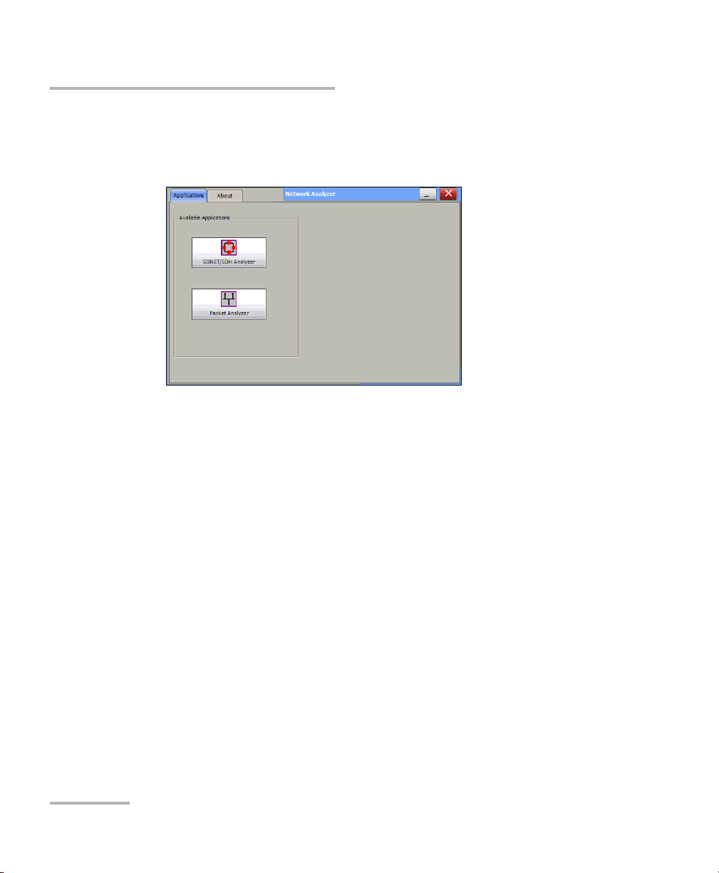
FTB-8510B/FTB-8510G/FTB-8525/FTB-8535 or the Network Analyzer for
FTB-8120NGE/FTB-8130NGE. The Network Analyzer application allows
to either run the SONET/SDH application or the Packet Analyzer
application. Both applications cannot run simultaneously.
Ethernet and Fibre Channel Application 33
Page 48
Introducing the Smart User Interface
Starting the Module Application
4. Fo r FTB-8120NGE/FTB-8130NGE only, on the Available Applications,
under the Applications tab, press Packet Analyzer to start the Smart
User Interface (SUI) for Ethernet and Fibre Channel test.
Refer to the SONET/SDH Application user guide for more information
on SONET/SDH.
The exit button ( X ) closes the Network Analyzer, SONET/SDH
Analyzer, and/or Ethernet Analyzer applications. If a test is created,
one of the following confirmation messages is displayed, based on the
standalone feature status (enabled or not). Refer to the FTB-500 user
guide for more information on the standalone feature.
Exiting the SUI while a test is created and standalone is disabled:
Are you sure you want to exit the Network Analyzer,
SONET/SDH Analyzer, and Ethernet Analyzer? Any unsaved
information will be lost.
Exiting the SUI while a test is created and standalone is enabled:
Exiting the application will maintain the module alive as the
Standalone mode is enabled. Are you sure you want to exit?
34 FTB-8500 Series and FTB-8120NGE/8130NGE
Page 49

Main Window
Application name
Minimize
Help
Exit
Ta bs
Ta b( s )
Ta b’ s
Content
Remote
status
Date and time
Battery level /
AC power
Tes t c o ntr o l s
Global test status
Introducing the Smart User Interface
Main Window
Ethernet and Fibre Channel Application 35
Page 50

Introducing the Smart User Interface
Main Window
Tabs
The SUI application contains the following four main application tabs that
contain other tabs.
TEST Tab
The TEST tab gives access to the test creation, configuration, and
results.
Note: Only the Setup tab is available when there is no test created.
Setup tab is part of the TEST tab and allows setting up the test. Refer to
page 66 for more information.
Once the test is created, other tabs containing one or two tabs are
enabled allowing configuration of test parameters and viewing of the
test status and results.
36 FTB-8500 Series and FTB-8120NGE/8130NGE
Page 51

Introducing the Smart User Interface
Port 1
Port 2
Main Window
For Dual ports (FTB-8510B only), see the figure below for the
localization of the port number on each tabs.
Ethernet and Fibre Channel Application 37
Page 52

Introducing the Smart User Interface
Main Window
In this user guide, the tabs are grouped as shown below:
Summary Tabs on page 119
Por t Tabs on page 131
Stream Generation Tabs on page 199
Stream Analyzer Tabs on page 237
Traffic Analyzer Tabs on page 159
IPTV Tabs on page 257 (FTB-8510B)
Patter n Tab s on page 251
RFC 2544 Tabs on page 297
EtherSAM Tabs on page 323
TCP Throughput Tabs on page 351 (not available on FTB-8510G)
Advanced Tab on page 357
WIS Tabs on page 241 (FTB-8510G, FTB-8535, and FTB-8130NGE)
Common Tab on page 361
Expert Mode Tabs on page 423
System tab; refer to page 365 for more information.
Tool s tab; refer to page 389 for more information.
About tab; gives information on EXFO company, contact, and product
software release version.
38 FTB-8500 Series and FTB-8120NGE/8130NGE
Page 53

Introducing the Smart User Interface
Main Window
Application Title
Displays the software application title which is [x] - EXFO followed by the
application name. Where x is the slot ID in which the module is inserted.
A module description appears in front of the [x] slot ID when defined in
ToolBox. Refer to Too ls, Remote Control Configuration and Module
Description field from the FTB-500 user guide for more information.
For Visual Guardian Lite, the IP address of the FTB-500 is inserted after the
[x] slot ID.
For example: Module #1 - [2] - 10.1.200.25 - EXFO Packet Blazer
Minimize
The minimize button ( _ ) allows minimization of a remote SUI application
(Visual Guardian Lite).
Ethernet and Fibre Channel Application 39
Page 54
Introducing the Smart User Interface
Main Window
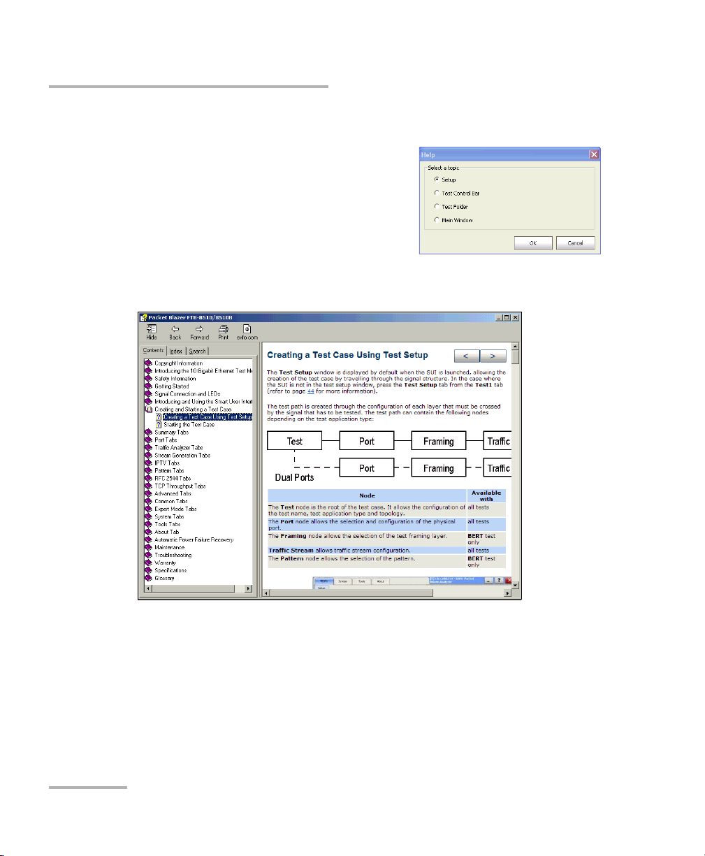
Help
The help button ( ? ) displays the help
information on the current window. A
window pops up to select the area of the
application where help is required. Press
OK and the help information is
immediately displayed.
It is also possible to navigate through the
help information once the help window is open.
40 FTB-8500 Series and FTB-8120NGE/8130NGE
Page 55

Introducing the Smart User Interface
Main Window
Exit
For FTB-8510B, FTB-8510G, FTB-8525, and FTB-8535:
The exit button ( X ) closes the current application. If a test is created,
one of the following confirmation messages is displayed, based on the
standalone feature status (enabled or not). Refer to the FTB-500 user
guide for more information on the standalone feature.
The following message is displayed when exiting the SUI while a
test is created and standalone is disabled:
Are you sure you want to exit the Ethernet and Fibre Channel
Application? Any unsaved information will be lost.
The following message is displayed when exiting the SUI while a
test is created and standalone is enabled:
Exiting the application will maintain the module alive as the
Standalone mode is enabled. Are you sure you want to exit?
For FTB-8120NGE, and FTB-8130NGE:
The exit button ( X ) switches from the current application to the
Network Analyzer application. If the test is running, a user
confirmation is required to stop the test before switching the
application. The switching puts the application in idle mode meaning
that the test case configuration is kept and will be recovered when
returning to that application.
Ethernet and Fibre Channel Application 41
Page 56

Introducing the Smart User Interface
Global Test Status and Controls
Global Test Status and Controls
Global Test Status
The global test status area displays the alarm, verdict, and test timer.
Clicking on this area maximizes the view of these status. The maximized
view is useful to facilitate distant viewing of these status.
To minimize the view, either click on the global test status area or click
anywhere on the maximized status area.
H (History): Indicates that alarms/errors occurred in the past. A grey
background indicates that the test did not run yet, a green background
indicates that no alarm/error has occurred, while a red background
indicates that at least one alarm/error has occurred.
42 FTB-8500 Series and FTB-8120NGE/8130NGE
Page 57

Introducing the Smart User Interface
Global Test Status and Controls
Current status: Indicates the current alarm/error status of the test. A
grey background indicates that the test is not running (--), a green
background indicates that there is no alarm/error (NO ALARM), while
a red background indicates that at least one alarm/error condition has
occurred in the last second (ALARM).
Note: The history and current alarm/error status are monitored once the test is
started.
Verdict: Gives the verdict, PA SS (green background) or FAIL (red
background) of the test according to the defined threshold settings.
Verdict is only displayed with EtherSAM, RFC 2544, and BERT tests. For
RFC 2544 and BERT tests, at least one of the Enable criteria check
boxes must be selected. Refer to EtherSAM Tabs on page 323 or to
Expert Mode Tabs on page 423 (RFC 2544 and BERT tests) for more
information.
The test timer indicates the time elapsed since the beginning of the
test. The test timer format is day hour:minute:second.
Test Controls
Button Description
Start: Starts the test. Start is available when the test is created and not running.
a
Stop
: Stops the test.
H. Reset
Reset
(H) and current (C) LEDs for the entire test case. Also resets the logger.
Report
page 48 for more information.
New
the test.
Ethernet and Fibre Channel Application 43
a
: Resets the history (H) alarm and error LEDs.
a
: Resets counters (seconds, count, and rate), test timer and both history
b
: Generates a report of the current test. See Test Report Generation on
b
: Clears the current test. A user’s confirmation is required before clearing
Page 58
Introducing the Smart User Interface
Global Test Status and Controls
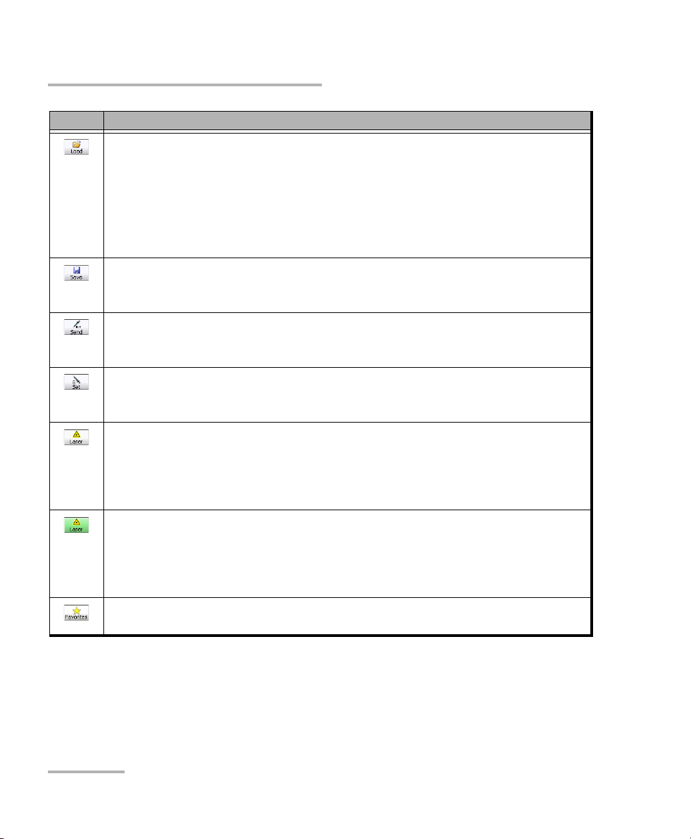
Button Description
Loadb: Loads a previously saved configuration. Select an existing file and press
Open to confirm. The default directory is
d:\ToolBox\User Files\PacketBlazerG2\Configuration. The configuration file
extension is cfg.
An error message is displayed and the configuration is not loaded when the file
is corrupted, the module is not properly installed, the hardware or software
options are not compatible, or when the resources or power are not sufficient.
b
Save
: Saves the current test configuration. Select an existing file, or type a new
name in the File name field, and press Save. The default directory is
d:\ToolBox\User Files\PacketBlazerG2\Configuration.
a
Send
: Generates pattern bit error according to the amount selected on the
Pattern TX tab. Refer to Pattern Error Injection on page 254. This button is only
available with BERT test.
a
Set
: Allows selecting the port that will be used for pattern bit error injection.
See Send button for error injection. This button is only available with BERT test
in Dual Ports topology. Available with FTB-8510B only.
Laser Off (grey): Indicates that the laser control is off. Pressing this button will
activate the laser immediately by emitting an optical laser signal. This button is
only available for optical interfaces. The laser is On by default when the test is
created unless otherwise set from the Default/Ethernet Test Preferences on
page 368.
Laser On (green): Indicates that the laser control is on. Pressing this button will
turn off the laser. This button is only available for optical interfaces. The laser is
On by default when the test is created unless otherwise set from the
Default/Ethernet Test Preferences on page 368. The laser control button is not
affected when turning off the laser by generating a LOS for example.
Favorites
b
: Provides access to 10 default or customer defined test case
configurations. See Favorites on page 46 for more information.
a. Only available when the test is running.
b. Only available when the test is not running (Stop).
44 FTB-8500 Series and FTB-8120NGE/8130NGE
Page 59

Introducing the Smart User Interface
Global Test Status and Controls
Remote Status
Indicates whether the remote control feature is enabled/disabled and
indicates the number of connections established with the FTB-8500 Series
and FTB-8120NGE/8130NGE when enabled.
Indicates that the remote control feature is disabled. Refer to the
FTB-500 user guide for more information on how to enable it.
Indicates that a single connection is established with the FTB-8500
Series and FTB-8120NGE/8130NGE. The connection can be either
local (on the FTB-500) or remote (on a remote PC using Visual
Guardian Lite).
Indicates that at least two connections are established with the
FTB-8500 Series and FTB-8120NGE/8130NGE. Connections can be
a combination of one local (on the FTB-500) and at least one
remote connection (on a remote PC using Visual Guardian Lite),
two or more remote connections.
Date and Time
Indicates the date (YYYY-MM-DD) and time (HH:MM:SS).
Refer to Time Options on page 366 for more information on time format
and time zone.
Battery Level/AC Power
Indicates the battery level of the FTB-500 when batteries are installed, or
indicates the presence of an AC power source when there is no battery
installed.
Note: The FTB-8500 Series and FTB-8120NGE/8130NGE module requires an AC
power source to operate.
Ethernet and Fibre Channel Application 45
Page 60

Introducing the Smart User Interface
Favorites
Favorites
Favorites gives access to 10 factory test case configurations. Favorites is
available when no test is running.
Press .
Favorites List
Allows to select a test case configuration. The test case configuration
selected by default is the first one in the list.
Note: Test cases not supported by the current FTB-8500 Series and
FTB-8120NGE/8130NGE model and its options will not be created.
Note: Favorites may or may not be compatible from one version of software to
another. They also may or may not be compatible from one module to
another depending on the hardware and software option installed.
46 FTB-8500 Series and FTB-8120NGE/8130NGE
Page 61

Introducing the Smart User Interface
Favorites
Overwrite Selected Favorite Content
The factory test case configurations can be modified as well as their
default names.
Favorite Name: Allows changing the name of the test case
configuration file. A maximum of 32 characters are allowed in the
name.
Save: Saves the current test case configuration using the specified
favorite name.
Load
Loads the selected test case configuration. Loading a favorite configuration
automatically clears the current test case.
Factory Default
Restores the factory default favorites list based on the module model and
its enabled options.
Note: A Default Favorites list is created the first time a specific module is used,
based on its module type and options. A favorites list is generated for each
module type used (FTB-8525, FTB-8535, FTB-8120NGE and FTB-8130NGE).
The favorites list for a specific module type is common for all modules of
the same type on the FTB-500. The favorites list is not updated when either
a new software option is installed or another module having different
options is used. For these reasons, the Factory Default button allows to
recreate the favorites list based on the current module and its options.
Close
Closes the Fav orites window.
Ethernet and Fibre Channel Application 47
Page 62

Introducing the Smart User Interface
Test Report Generation
Test Report Generation
Press Report from the Global Test Status and Controls to generate a report
for the current test. The report contains all the information about the test
including the job information, system information, interface setup, test
summary, test configuration, results, etc.
Note: The Report button is not available while the test is running.
Note: Nothing prevents the configuration and alarm/error injection setup while
the test has been stopped; thus, the report should be saved before changing
any test parameters to avoid discrepancy between the configuration and
results.
Information Tab
Job Information: These parameters are used to identify the
source of the report and are not mandatory. Enter the following job
information if required: Job ID, Contractor, Customer, Operator
Name, and Comment. Up to 256 characters are allowed for each
parameter.
48 FTB-8500 Series and FTB-8120NGE/8130NGE
Page 63

Introducing the Smart User Interface
Test R e p or t Gene r a t io n
Report Settings: These parameters are used to identify the report
and are not mandatory. Enter the following report information if
needed: Report Title, Report Header, Selected Logo, and Report
Format.
Press Browse to select a different logo, then press Open.
Report Format: Select the report file format. Choices are html, csv,
pdf, and txt. The CSV format (comma separated file format)
generates a report with comma delimiter for English OS and
semicolon for other OS languages. The default setting is html..
View Report After Generation: Allows displaying the report once
it is generated. However, the report can only be displayed when
the Windows application supporting the selected Report Format is
installed. The View Report After Generation check box is not
selected by default.
Note: Once generated, the report file can manually be opened typically using
Windows Explorer. The default directory is
d:\ToolBox\User Files\PacketBlazerG2\Reports.
Note: If the html report contains special characters, please make sure that the
encoding in your Web browser is set to Western European ISO. To set the
encoding to Western European ISO, right press the report from Internet
Explorer, select Encoding, and select Western European ISO.
Default button: Press Default to restore the default report settings.
Ethernet and Fibre Channel Application 49
Page 64

Introducing the Smart User Interface
Test Report Generation
Generate button: Allows generating and saving the report. Select
an existing file, or type a new name in the File name field and
press OK. The default directory is
d:\ToolBox\User Files\PacketBlazerG2\Reports.
The report file can be saved on the following locations:
Local memory (FTB-500): The file is saved locally on the FTB-500
memory.
Network drive: The file is saved on a network drive.
USB drive or Compact Flash: The file is saved on a removable
drive.
Close button: Closes the report generation settings window.
50 FTB-8500 Series and FTB-8120NGE/8130NGE
Page 65

Introducing the Smart User Interface
Test R e p or t Gene r a t io n
Sections Tab
Pre-defined selection: Allows selecting the type of report, and the
window underneath allows selecting what will be part of the
report. The default setting is Summary Report. Choices are:
Summary Report selects the Summary report section only.
Test Case Report selects all the report sections.
Note: Once the report type is selected, each section can be selected to customize
the report.
The Select All and Deselect All buttons are used to respectively select
or deselect all the report sections.
Ethernet and Fibre Channel Application 51
Page 66

Introducing the Smart User Interface
Typic a l Tab El em ents
Typical Tab Elements
Once the test is created, different tabs are available allowing test
configuration and monitoring. The following section describes usual
elements appearing on those tabs.
Status LEDs
H (History) LED: Indicates that alarms/errors occurred in the past. A
grey LED indicates that the test did not run yet, a green LED indicates
that no alarm/error has occurred, while a red LED indicates that at
least one alarm/error has occurred in the test.
C (Current) LED: Gives the current status of the alarm/error. A grey LED
indicates that the test is not running, a green LED indicates that there is
no alarm/error, while a red LED indicates that at least one alarm/error
condition has occurred in the last second.
Note: The H and C LEDs are updated every second.
52 FTB-8500 Series and FTB-8120NGE/8130NGE
Page 67

Introducing the Smart User Interface
Alarm/Error Measurements
Note: Alarms/Errors are only monitored once the test is started.
Seconds: Gives the total number of the seconds in which one or more
alarm/error occurred.
Count: Gives the number of occurrences of a specific error. The count
is displayed using integer value; exponential value (1.00000E10) is used
when the count is bigger than the field display capacity.
Rate: Calculates and displays the error rate. The rate is expressed using
the exponential format with two decimal digits (example: 1.23E-04).
Arrow Buttons
Button Description
Top arrow: Moves to the top of the list.
Typical Tab Elements
Page up arrow: Moves one page up.
Up arrow: Moves one event up.
Down arrow: Moves one event down.
Page down arrow: Moves one page down.
End arrow: Moves to the end of the list.
Ethernet and Fibre Channel Application 53
Page 68

Introducing the Smart User Interface
Ta b l e So r t
Left and Right scroll buttons
Typic a l Tab El em ents
Table Sorting
Tables offer sorting capabilities on one or more columns.
An arrow next to the column label name, indicates the sorting column field
and the sorting order. Pressing again on the selected sort column label will
change the sort order.
Pressing another column label allows to sort using a different field.
Left and Right Scroll Buttons
Left and right scroll buttons are used to respectively move left and right
allowing to see more tabs. The left and right scroll buttons are not always
displayed; they are only displayed when required.1
54 FTB-8500 Series and FTB-8120NGE/8130NGE
Page 69

Introducing the Smart User Interface
Tab Configuration buttons
Top t ab
Page/Tab
Bottom tab
Tab Configuration
Tab Configuration
Once the test is created, other tabs next to the Test tabs are enabled
allowing configuration of test parameters and viewing of the test status and
results.
A tab configuration button is available at the top-right part of each tab.
Ethernet and Fibre Channel Application 55
Page 70

Introducing the Smart User Interface
Tab Configuration
This tab configuration window allows configuration of all tabs on any page
except for the Te s t Setup , and Summary tabs. The tab configuration allows
also to jump directly to the desired page by selecting it from the Defined
Tab s list and then pressing OK.
Selected Tab
Tab N a me indicates the name of the tab containing the two tabs (top
and bottom page). Pressing this field allows changing the tab name.
Tab name can be up to 35 characters long including the “/” and spaces.
Top Pag e indicates the tab displayed at the top of the tab.
Bottom Page indicates the tab displayed at the bottom of the tab.
56 FTB-8500 Series and FTB-8120NGE/8130NGE
Page 71

Introducing the Smart User Interface
Tab Configuration
Defined Tabs
Allows the selection of a tab.
Up and down arrows are used to respectively move the selected page up
or down in the list.
Insert button allows the insertion of a new tab after the selected tab (the
one highlighted) A maximum of 30 tabs can be displayed.
Delete button allows the deletion of the selected tab.
Page Selection
Typ e: Allows the selection of a tab that will be assigned to the selected
tab when pressing either Apply to top page or Apply to bottom page.
Path: Indicates the test signal structure (layers/nodes of the test case)
corresponding to the selected tab. Refer to Introducing the Test Setup
on page 66 for more information on test layers/nodes.
Apply To Top Page: Applies the selected tab as top of page for the
selected tab.
Apply To Bottom Page: Applies the selected tab as bottom of page for
the selected tab.
Note: The available tabs listed are a function of the test path activated. Empty
Ta b displays a blank tab (Tabs that are not populated are left blank). Tes t
Setup and Summary tabs cannot be duplicated, deleted, or renamed.
Ethernet and Fibre Channel Application 57
Page 72

Introducing the Smart User Interface
Tab Configuration
Help Button (?)
Displays the help information related to the tab configuration. It is also
possible to navigate through the remainder of the help information.
Default Button
Return to the default page configuration layout.
OK Button
Accepts the page layout changes and jumps to the selected page (Defined
tabs).
Cancel Button
Cancels the changes and returns to the page from where the tab
configuration was launched.
58 FTB-8500 Series and FTB-8120NGE/8130NGE
Page 73

Introducing the Smart User Interface
Keyboard Usage
Keyboard Usage
The SUI pops up different keyboards to modify data. Following are the
usual keyboard keys:
Left arrow: Moves the cursor one position to the left.
Right arrow: Moves the cursor one position to the right.
Del: Deletes the value at the cursor position.
Back: Deletes the value preceding the cursor position.
Help: Displays the help information related to the keyboard usage.
It is also possible to navigate through the help information.
OK and Enter: Completes data entry.
Cancel: Closes the keyboard and discards the keyboard entry.
Binary keyboard: Allows entering 0 and 1 values.
Ethernet and Fibre Channel Application 59
Page 74

Introducing the Smart User Interface
Keyboard Usage
Numerical keyboards: Allows entering integer/decimal values.
For integer unsigned or signed values
For rate values: Allows entering the rate values (0 through 9, and
exponent)
For IP address, Subnet Mask and Default Gateway values
60 FTB-8500 Series and FTB-8120NGE/8130NGE
Page 75

Introducing the Smart User Interface
Keyboard Usage
Time Keyboard: Allows entering a time value.
Date keyboard: Allows selecting a date by pressing the date on the
calendar. Use the left and right arrow to switch from one month to
another or press the month area for quick month selection. Press the
year area for quick year selection.
Ethernet and Fibre Channel Application 61
Page 76

Introducing the Smart User Interface
Keyboard Usage
Hexadecimal keyboards: Allows entering hexadecimal values
(0 through 9 and A through F)
For MAC address
For IPv6 address
62 FTB-8500 Series and FTB-8120NGE/8130NGE
Page 77

Introducing the Smart User Interface
Keyboard Usage
Full keyboard: Allows entering numbers, letters and some other
characters. The Back, Del, Shift and space bar keys have the same
functionality as a regular PC keyboard.
Trace message keyboard (WAN): Allows entering alphanumerical
characters (ITU T.50) required for J0 and J1 Trace fields. Press the
Ctrl Char button to access these characters.
Ethernet and Fibre Channel Application 63
Page 78

Introducing the Smart User Interface
Keyboard Usage
ITU T.50 Characters
b7 to b1 Character Description b7 to b1 Character Description
000 0000 NUL Null 001 0000 DLE Data Link Escape
000 0001 SOH Start Of Heading 001 0001 DC1 Device Control 1
000 0010 STX Start of Text 001 0010 DC2 Device Control 2
000 0011 ETX End of Text 001 0011 DC3 Device Control 3
000 0100 EOT End Of Transmission 001 0100 DC4 Device Control 4
000 0101 ENQ Enquiry 001 0101 NAK Negative
Acknowledge
000 0110 ACK Acknowledge 001 0110 SYN Synchronous idle
000 0111 BEL Bell 001 0111 ETB End of Transmission
Block
000 1000 BS Backspace 001 1000 CAN Cancel
000 1001 HT Horizontal
001 1001 EM End of Medium
Tab ul at io n
000 1010 LF Line Feed 001 1010 SUB Substitute character
000 1011 VT Vertical Tabulation 001 1011 ESC Escape
000 1100 FF Form Feed 001 1100 IS4 Information
Separator 4
000 1101 CR Carriage Return 001 1101 IS3 Information
Separator 3
000 1110 SO Shift-Out 001 1110 IS2 Information
Separator 2
000 1111 SI Shift-In 001 1111 IS1 Information
Separator 1
64 FTB-8500 Series and FTB-8120NGE/8130NGE
Page 79

6 Creating and Starting a
Test Case
A test case can be created using one of the following methods:
Test S e tup allows the creation of the test case by travelling through the
signal structure. See Introducing the Test Setup on page 66.
See Test Case Availability to determine the test cases supported by the
unit.
Load allows setting up the test case by loading a previously saved
configuration. Refer to Load on page 44 for more information.
Script allows running a script that creates the test case. Refer to Script
on page 390.
Ethernet and Fibre Channel Application 65
Page 80

Creating and Starting a Test Case
Data Path
Selector
Configuration
section
Te s t S et u p
Controls
Introducing the Test Setup
Introducing the Test Setup
The Test S et up window is displayed by default when the SUI is started. In
the case where the SUI is not in the test setup window, press the Tes t
Setup tab from the TEST Tab on page 36.
Tree allows seeing the configuration test structure (data path).
Grid is used for test case direction (decoupled test mode).
Data Path Selector is used to select the datapath structure (for
example: port, signal, Pattern, etc.) of the test case.
Configuration section allows parameters configuration for each node
of the test.
Test N ame represents the name of the test connection used to identify
the test. The default setting is TEST.
Note: The other configuration section parameters are described for each specific
test.
66 FTB-8500 Series and FTB-8120NGE/8130NGE
Page 81

Creating and Starting a Test Case
Introducing the Test Setup
Test S etup Co ntr o ls:
Back returns to the previous configuration step allowing to see,
change or delete what had been selected.
Next switches to the next configuration step. The Next button is
only available when selection(s) from the Data Path Selector
and/or the Grid has been made.
Delete deletes the current path node.
Finish/Setup:
Finish completes the configuration and creates the test case. The
current window settings are only accepted if the selection has
been made from the Grid view. Default parameters will be used
for the remaining wizard steps. Thus, pressing Finish for BERT test
will automatically add a pattern at the end of the test case structure
if not already selected.
Setup is displayed instead of Finish once the test is created
allowing to return in setup mode. Setup is not available when the
test is started (running).
Ethernet and Fibre Channel Application 67
Page 82

Creating and Starting a Test Case
Introducing the Test Setup
The test path is created through the configuration of each layer that must
be crossed by the signal under test. The test path can contain the following
steps depending on the test application type:
For FTB-8510B:
For FTB-8510G:
For FTB-8120NGE/FTB-8130NGE and FTB-8525/FTB-8535:
68 FTB-8500 Series and FTB-8120NGE/8130NGE
Page 83

Creating and Starting a Test Case
Introducing the Test Setup
Steps
The Test step is the root of the test case. It allows the configuration
Available with
All tests
of the test name, test application type, Interface Type, topology, and
Clock Mode. For RFC 2544, the selection of the sub tests and dual
test set are also available.
The Port step allows the selection and configuration of the physical
All tests
port and for 10Gig-E interface the configuration of the transceiver
mode (LAN or WAN). For WAN transceiver mode, the WIS step will
be inserted in front of the Framing step.
The WIS step indicates that the WAN transceiver mode is selected.
Available with 10Gig-E interface only.
WAN transceiver
mode only
The Framing step allows the selection of the test framing layer. All tests
The Network step allows the selection of the network
Ethernet/Fibre Channel parameters for the port.
All test at the
exception of BERT
Unframed,
Framed Layer1
and Fibre Channel
The Traffic Stream step allows traffic stream configuration. All Ethernet tests
except
Smart Loopback
The Remote Module step allows the selection of a remote
compatible module (FTB-8510B, FTB-8510G, FTB-8525/FTB-8535,
FTB-8120NGE/FTB-8130NGE, and RTU-310/RTU-310G).
EtherSAM and
RFC 2544 Dual
Test S ets tests
only
The Pattern step allows the selection of the pattern. BERT test only
Ethernet and Fibre Channel Application 69
Page 84

Creating and Starting a Test Case
Test C a s e Availa b i li ty
Test Case Availability
The remaining of this chapter describes how to create the following typical
Ethernet and Fibre Channel test cases. The available test cases depend on
the model and activated options.
Supported on
Test Case
FTB-8510B FTB-8510G FTB-8525
FTB-8535
FTB-8120NGE
FTB-8130NGE
EtherSAM (Y.1564) Test Case XXX X71
Page
Ethernet EtherSAM (Y.1564) and RFC
XXX X78
2544 Dual Test Set Test Cases
Ethernet RFC 2544 Test Case XXX X87
Ethernet BERT Test Case XXX X93
Ethernet Frame Analyzer Test Case
XX
a
a
X
a
X
100
including Multiple-Stream, Through
Mode, MPLS, and PBB-TE testing.
Ethernet Smart Loopback Test Case X X X X 107
Ethernet TCP Throughput Test Case X X X 111
Fibre Channel BERT Test Case X X X 114
a. Through Mode only available on the FTB-8510B.
70 FTB-8500 Series and FTB-8120NGE/8130NGE
Page 85

Creating and Starting a Test Case
EtherSAM (Y.1564) Test Case
EtherSAM (Y.1564) Test Case
ITU-T Y.1564 is the newly introduced standard for turning-up and
troubleshooting carrier Ethernet services. This new methodology is
completely adapted to today’s Ethernet services especially mobile
backhaul and commercial services.
Contrary to other methodologies, EtherSAM supports new multiservice
offerings. It can simulate all types of services that will run on the network
and simultaneously qualify all key SLA parameters for each of these
services. Moreover, it validates the QoS mechanisms provisioned in the
network to prioritize the different service types, resulting in more accurate
validation and much faster deployment and troubleshooting.
Typ ic al EtherSAM (Y.1564) application:
Note: For bi-directional (Dual Test Set) test, see Ethernet EtherSAM (Y.1564) and
RFC 2544 Dual Test Set Test Cases on page 78.
Ethernet and Fibre Channel Application 71
Page 86
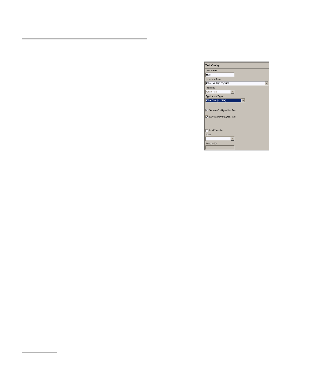
Creating and Starting a Test Case
EtherSAM (Y.1564) Test Case
To create an EtherSAM (Y.1564) test case:
1. Test configuration:
1a. Select Ethernet 10/100/1000 or
Ethernet 10G as the Interface Type.
Interface Type is not available with
FTB-8510G.
1b. Select Single Port as the Top olog y.
Topology is only available with
FTB-8510B.
1c. Select the source Clock Mode.
Available with FTB-8510G only. Refer to
Clock Synchronization on page 383 for
more information.
1d. Select EtherSAM (Y.1564) as the Application Type.
1e. Select the desired EtherSAM sub test(s). All EtherSAM sub tests
are selected by default. Refer to Overview (Configuration) on
page 324 and Services (Configuration) on page 329 for more
information.
Service Configuration Test consists in sequentially testing each
service. It validates that the service is properly provisioned and
that all specific KPIs or SLA parameters are met.
Service Performance Test simultaneously validates the quality of
all the services over time.
1f. Leave the Dual Test Set check box cleared. For Dual Test Set test
case, refer to Ethernet EtherSAM (Y.1564) and RFC 2544 Dual Test
Set Test Cases on page 78.
1g. Press Next.
72 FTB-8500 Series and FTB-8120NGE/8130NGE
Page 87

2. Port configuration:
2a. Select the port Connector
Type (Optical or
Electrical RJ-45). Optical is automatically selected for the
Ethernet 10G interface.
2b. For FTB-8510B, select the
port number by pressing
on Port 1 or Port 2.
2c. For Electrical RJ-45, if
required, select the Ethernet port
crossover check box to inverse the
pin-to-pair assignment of the UTP cable used.
Creating and Starting a Test Case
EtherSAM (Y.1564) Test Case
Note: At this point you should have a link up indicated in the Tr ee view tab. A
green LED indicates a link up while a red LED indicates a link down. For
electrical port, if the link is down, make sure that the Ethernet port
crossover setting is correct.
2d. Press Next.
Ethernet and Fibre Channel Application 73
Page 88

Creating and Starting a Test Case
EtherSAM (Y.1564) Test Case
3. Optical configuration for Ethernet 10G interface only:
3a. Select the Transc eiver Mode Choices
are Local Area Network (LAN) for
regular Ethernet interface
(10.31250Gb/s) and Wide Area Network
(WAN) for Ethernet stream
encapsulated inside a SONET/SDH frame structure (9.95328Gb/s).
Choices availability depend on the unit model and options refer to
Software Options on page 378 for more information.
3b. Select the source Clock Mode (WAN transceiver mode only).
Refer to Clock Synchronization on page 383 for more information.
3c. Press Next.
3d. Enter the J0 Trace and J1 Trace
messages (WAN transceiver mode
only). Refer to WIS TX on page 241 for
more information.
3e. Press Next.
4. Port and framing
configuration:
4a. Set the
Auto-Negotiation,
Speed, Duplex, and
Flow Control
parameters. Not
available with Ethernet
10G. Refer to Interface
Setup (Ethernet) on
page 140 for more
information.
4b. Set the VLAN parameters when required. Refer to Network on
page 148 for more information.
74 FTB-8500 Series and FTB-8120NGE/8130NGE
Page 89

Creating and Starting a Test Case
EtherSAM (Y.1564) Test Case
4c. Select the Frame Format. Choices are Ethernet II and
802.3 SNAP. For 802.3 SNAP, select the Organizationally Unique
Identifier (OUI). Refer to Network on page 148 for more
information.
4d. Select the PBB-TE check box to enable the capability to generate
and analyze streams with PBB-TE data traffic including
configuration of B-MAC (source and destination), B-VLAN and
I-tag, and to filter received traffic by any of these fields. PBB-TE is
a software option and needs to be enabled to give access to the
PBB-TE testing capability (refer to Software Options on page 378).
PBB-TE is not available when the MPLS check box is selected.
Refer to PBB-TE Interface configuration on page 481 for more
information.
Select the MPLS check box to enable the capability to generate
and analyze streams with up to two layers of MPLS labels and to
filter received traffic by MPLS label or COS. MPLS is a software
option and needs to be enabled to give access to the MPLS testing
capability (refer to Software Options on page 378). MPLS is not
available when the PBB-TE check box is selected. Refer to MPLS
Configuration on page 497 for more information.TX and RX:
Allows the selection of the interface MPLS TX and RX labels (0 to
1048575). The default label value is 16 for both TX and RX. The
TX and RX labels are available when the MPLS check box is
selected. Refer to Network on page 148 for more information.
4e. Set the IP Version (IPv4 or IPv6). IP Version is only available
when the IPv6 software option (SK-IPV6) is enabled.
4f. For IPv4, select the Automatic IP Address check box to
dynamically obtain an IP address from a DHCP (Dynamic Host
Configuration Protocol) server or set the source and destination IP
addresses, Subnet Mask, and the Default Gateway. Refer to IPv4
Configuration on page 483 for more information.
Ethernet and Fibre Channel Application 75
Page 90

Creating and Starting a Test Case
EtherSAM (Y.1564) Test Case
4g. For IPv6, press the IPv6 Config button to set the IPv6 settings.
Refer to IPv6 Address Configuration on page 485 for more
information.
4h. Press Next.
5. Service configuration
5a. For IPv4, select the Automatic IP
Address check box to dynamically
obtain an IP address from a DHCP
(Dynamic Host Configuration Protocol)
server or set the source and destination
IP addresses, Subnet Mask, and the
Default Gateway. Refer to IPv4
Configuration on page 483 for more
information.
5b. For IPv6, set the destination IP address
and if required, press the IPv6 Config
button for additional IPv6 settings. Refer
to IPv6 Address Configuration on
page 485 for more information.
5c. If required, set the source and
destination MAC addresses, and select
the Resolve MAC Address check box
when required. Refer to page 330 for
more information.
5d. Select the Frame Format. Choices are
Ethernet II and 802.3 SNAP. Refer to Framing Configuration on
page 492 for more information.
5e. Set the VLAN parameters when required. Refer to VLAN
Configuration on page 480 for more information.
5f. Press Finish to complete the test setup.
76 FTB-8500 Series and FTB-8120NGE/8130NGE
Page 91

Creating and Starting a Test Case
EtherSAM (Y.1564) Test Case
6. Services must be enabled before starting the test. For enabling Services
and for additional configuration parameters, refer to EtherSAM Tabs on
page 323.
7. Press the Start button to start the test.
At least one of the EtherSAM (Y.1564) sub tests (Service Configuration
Test or Service Performance Test) has to be enabled to start the test.
The sub-tests that are enabled will be performed following this order:
Service Configuration Test and Service Performance Test.
8. For additional results, refer to EtherSAM Tabs on page 323.
Ethernet and Fibre Channel Application 77
Page 92

Creating and Starting a Test Case
Ethernet EtherSAM (Y.1564) and RFC 2544 Dual Test Set Test Cases
Ethernet EtherSAM (Y.1564) and RFC 2544 Dual
Test Set Test Cases
The EtherSAM (Y.1564) test allows to validate the key performance
indicators of Carrier Ethernet-based services.
The RFC 2544 test allows Ethernet Throughput, Back-to-Back, Frame
Loss, and Latency performance tests in accordance with RFC 2544
specifications.
Dual Test Set test allows bi-directional test between two compatible
modules providing independent results for each test direction. Compatible
modules are FTB-8510B, FTB-8510G, FTB-8525/FTB-8535,
FTB-8120NGE/FTB-8130NGE, or RTU-310/RTU-310G. A Dual Test Set test
case must be first created on the remote module then on the local module
as described in the following procedure. The results from local-to-remote
and remote-to-local are available on the local testing unit.
78 FTB-8500 Series and FTB-8120NGE/8130NGE
Page 93
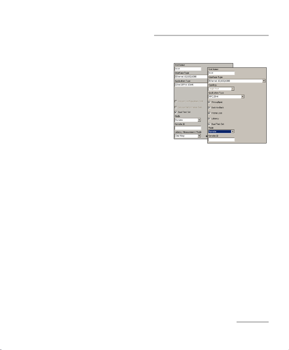
Creating and Starting a Test Case
Ethernet EtherSAM (Y.1564) and RFC 2544 Dual Test Set Test Cases
To create an EtherSAM (Y.1564) or RFC 2544 Dual Test Set test
case, first create the test on the remote module as follow:
1. Test configuration:
1a. Select
Ethernet 10/100/1000 or
Ethernet 10G as the
Interface Type. Interface
Typ e is not available with
FTB-8510G.
1b. Select Single Port as the
Top ol og y. Topology is only
available with FTB-8510B.
1c. Select EtherSAM (Y.1564)
or RFC 2544 as the Application Type.
1d. Select the Dual Test Set check box to enable the control of a
remote compatible module (FTB-8510B, FTB-8510G,
FTB-8525/FTB-8535, FTB-8120NGE/FTB-8130NGE, or
RTU-310/RTU-310G). For FTB-8510B, Dual Test Set is only
available in Single Port Top ol ogy. This setting is not selected by
default.
1e. Select the Remote test Mode.
1f. Type an ID for this remote unit. Up to 16 characters are allowed.
1g. For FTB-8120NGE and FTB-8130NGE, select the latency
measurement mode; Round-Trip or One-Way. For more
information, refer to Latency Measurement on page 301 for
RFC-2544, or Latency Measurement on page 327 for EtherSAM.
1h. Press Next.
Ethernet and Fibre Channel Application 79
Page 94

Creating and Starting a Test Case
Ethernet EtherSAM (Y.1564) and RFC 2544 Dual Test Set Test Cases
2. Port configuration:
Port 1 (FTB-8510B only) is automatically selected.
2a. Select the port Connector
Type (Optical or
Electrical RJ-45). Optical is automatically selected for the
Ethernet 10G interface.
2b. For Electrical RJ-45, if required, select
the Ethernet port crossover check box
to inverse the pin-to-pair assignment of
the UTP cable used.
Note: At this point you should have a link up indicated in the Tr ee view tab. A
green LED indicates a link up while a red LED indicates a link down. For
electrical port, if the link is down, make sure that the Ethernet port
crossover setting is correct.
2c. Press Next.
80 FTB-8500 Series and FTB-8120NGE/8130NGE
Page 95

Creating and Starting a Test Case
Ethernet EtherSAM (Y.1564) and RFC 2544 Dual Test Set Test Cases
3. Optical configuration for Ethernet 10G interface only:
3a. Select the Transc eiver Mode Choices
are Local Area Network (LAN) for
regular Ethernet interface
(10.31250Gb/s) and Wide Area Network
(WAN) for Ethernet stream
encapsulated inside a SONET/SDH frame structure (9.95328Gb/s).
Choices availability depend on the unit model and options refer to
Software Options on page 378 for more information.
3b. Select the source Clock Mode (WAN transceiver mode only).
Refer to Clock Synchronization on page 383 for more information.
3c. Press Next.
3d. Enter the J0 Trace and J1 Trace
messages (WAN transceiver mode
only). Refer to WIS TX on page 241 for
more information.
3e. Press Next.
Ethernet and Fibre Channel Application 81
Page 96
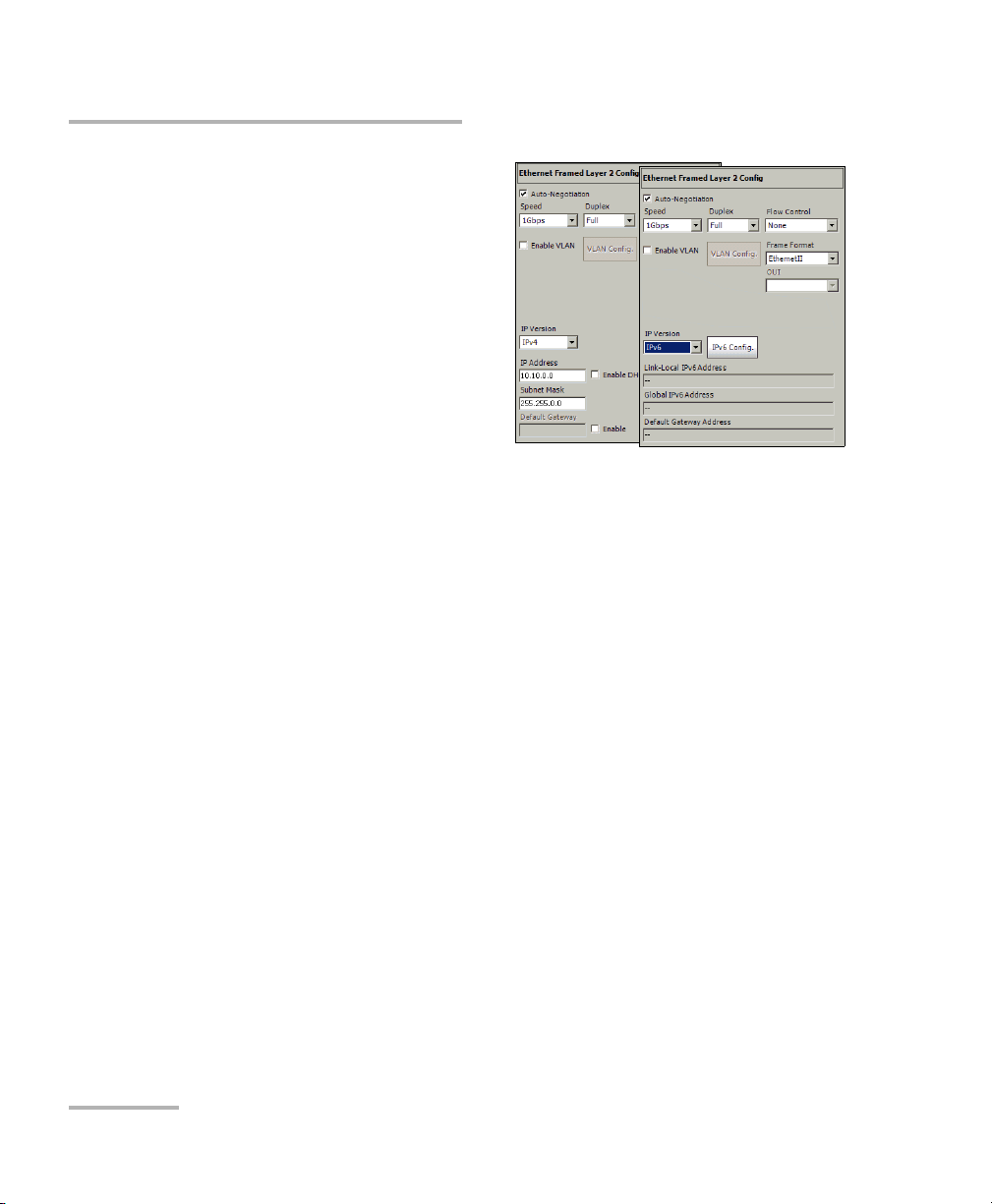
Creating and Starting a Test Case
Ethernet EtherSAM (Y.1564) and RFC 2544 Dual Test Set Test Cases
4. Framing configuration.
4a. Set the Auto-Negotiation,
Speed, Duplex, and Flow
Control parameters. Not
available with Ethernet
10G. Refer to Interface
Setup (Ethernet) on
page 140 for more
information.
4b. Set the VLAN parameters
when required. Refer to
MAC on page 218 for more information.
4c. Select the Frame Format. Choices are Ethernet II and 802.3
SNAP. Refer to Network on page 148 for more information.
4d. Set the IP Version (IPv4 or IPv6). IP Version is only available
when the IPv6 software option (SK-IPV6) is enabled.
4e. For IPv4, select the Automatic IP Address check box to
dynamically obtain an IP address from a DHCP (Dynamic Host
Configuration Protocol) server or set the source and destination IP
addresses, Subnet Mask, and the Default Gateway. Refer to IPv4
Configuration on page 483 for more information.
4f. For IPv6, press the IPv6 Config button to set the IPv6 settings.
Refer to IPv6 Address Configuration on page 485 for more
information.
4g. Press Finish to complete the test setup on this remote module.
The RFC 2544’s Global tab is automatically displayed.
When the test is created as remote on a unit or on a compatible unit
(FTB-8510B, FTB-8510G, FTB-8525/FTB-8535,
FTB-8120NGE/FTB-8130NGE, or RTU-310/RTU-310G), the SUI is limited
to the following: Test Setup, Tools, System, and About tabs; favorites,
save, load, and report functionality. No test configuration and results
are available.
82 FTB-8500 Series and FTB-8120NGE/8130NGE
Page 97

Creating and Starting a Test Case
Ethernet EtherSAM (Y.1564) and RFC 2544 Dual Test Set Test Cases
Create the test on the local module as follow:
1. On the local module, proceed with the test creation as described
above (starting with step 1 on page 79) at the exception of the
following parameters:
1a. Select the desired EtherSAM (Y.1564) or RFC 2544 sub test(s). All
sub tests are selected by default.
For RFC 2544:
Throughput: Gives the maximum throughput of the device under
test for which there is no frame loss. Refer to Throughput on
page 302 for more information.
Back-to-Back: Gives the maximum number of frames that can be
sent at maximum throughput. Refer to Back-to-Back on page 307
for more information.
Frame Loss: Gives the percentage of frames that are lost. Refer to
Frame Loss on page 311 for more information.
Latency: Gives the time required for the sent frame to go through
the device under test. Refer to Latency on page 315 for more
information.
For EtherSAM (Y.1564):
Service Configuration Test consists in sequentially testing each
service. It validates that the service is properly provisioned and
that all specific KPIs or SLA parameters are met.
Service Performance Test simultaneously validates the quality of
all the services over time.
1b. For Dual Test Set Mode (see step 1e on page 79), select the Local
test mode.
Ethernet and Fibre Channel Application 83
Page 98

Creating and Starting a Test Case
IPv4 IPv6
Ethernet EtherSAM (Y.1564) and RFC 2544 Dual Test Set Test Cases
1c. From the Remote Module page, press the Remote Selection
button.
1d. If both modules (remote and local) are on the same subnet,
select the subnet mask (Broadcast Destination) of the network
to be scanned, based on the IP address and subnet of its
interface. Available with IPv4 only.
If the remote and local modules are not on the same subnet, like
when connected through a Router, enter the remote module IP
address in the IP Address field of the Remote Module
Connection section. For IPv6, entering a Global IPv6 destination
address requires that the interface Global IPv6 Address is
defined. The Remote ID and its Status are displayed if the module
is detected. Skip to step 1g.
84 FTB-8500 Series and FTB-8120NGE/8130NGE
Page 99

Creating and Starting a Test Case
Ethernet EtherSAM (Y.1564) and RFC 2544 Dual Test Set Test Cases
1e. Press Scan Subnet to scan the subnet to find remote compatible
modules (FTB-8510B, FTB-8510G, FTB-8525/FTB-8535,
FTB-8120NGE/FTB-8130NGE, AXS-850 Series (RFC 2544 only),
FTB-860 Series, FTB-810/880 Series, or RTU-310/RTU-310G). The
subnet scan will work only when both remote and local modules
are on the same subnet. Only modules running the same test
(RFC 2544 or EtherSAM) and having the Remote Dual Test Set
mode enabled will be listed.
The detected remote compatible module are listed with their IP
Address, Remote ID, and Status information.
Status Description
Not Connected The remote module is not connected to another module.
Busy The remote module is connected to another module.
Connected The remote module is connected to the current module.
Remote IP not
found
The local module didn’t receive any reply from the
selected remote module IP address.
1f. Select a detected module from the list by pressing on it, and press
Select. The connection is possible with a module having its status
Not Connected or Busy. A confirmation is required when
selecting a remote module having its status Busy since the
remote unit may be connected to another module.
1g. Press the Connect button to establish the connection with the
remote module. The connection is possible with a module having
its status Not Connected or Busy. A confirmation is required
when selecting a remote module having its status Busy since the
remote unit may be connected to another module.
Disconnect allows to disconnect from the remote module.
1h. Press Finish to complete the test setup on this local module. For
RFC 2544, the RFC 2544’s Global tab is automatically displayed.
Ethernet and Fibre Channel Application 85
Page 100

Creating and Starting a Test Case
Ethernet EtherSAM (Y.1564) and RFC 2544 Dual Test Set Test Cases
2. For additional configuration parameters, refer to EtherSAM Tabs on
page 323 or RFC 2544 Tabs on page 297.
3. On the local module, press the Start button to start the test. The Start
button will be available only when the connection between the two
FTB-8500 Series and FTB-8120NGE/8130NGE units is established.
At least one of the test procedures (For EtherSAM (Y.1564): Service
Configuration Test or Service Performance Test; For RFC 2544:
Throughput, Back-to-Back, Frame Loss or Latency) has to be enabled
to start the test. Test procedures that are enabled will be performed
following this order:
Service Configuration Test and Service Performance Test for
EtherSAM (Y.1564)
Throughput, Back-to-Back, Frame Loss, and Latency for RFC 2544.
4. For additional results, refer to EtherSAM Tabs on page 323 or RFC 2544
Tab s on page 297.
86 FTB-8500 Series and FTB-8120NGE/8130NGE
 Loading...