

Page 1
ETHERNET AND MULTISERVICE TESTER
FTB-700G/800 Series
NetBlazer for FTB-1
User Guide
Page 2

Copyright © 2014 EXFO Inc. All rights reserved. No part of this publication
may be reproduced, stored in a retrieval system or transmitted in any form,
be it electronically, mechanically, or by any other means such as
photocopying, recording or otherwise, without the prior written permission
of EXFO Inc. (EXFO).
Information provided by EXFO is believed to be accurate and reliable.
However, no responsibility is assumed by EXFO for its use nor for any
infringements of patents or other rights of third parties that may result from
its use. No license is granted by implication or otherwise under any patent
rights of EXFO.
EXFO’s Commerce And Government Entities (CAGE) code under the North
Atlantic Treaty Organization (NATO) is 0L8C3.
The information contained in this publication is subject to change without
notice.
Trademarks
EXFO’s trademarks have been identified as such. However, the presence
or absence of such identification does not affect the legal status of any
trademark.
Units of Measurement
Units of measurement in this publication conform to SI standards and
practices.
July 9, 2014
Version number: 1.0.0
ii FTB-700G/800 Series
Page 3

Certification Information
Certification Information
North America Regulatory Statement
This unit was certified by an agency approved in both Canada and the
United States of America. It has been evaluated according to applicable
North American approved standards for product safety for use in Canada
and the United States.
Electronic test and measurement equipment is exempt from FCC part 15,
subpart B compliance in the United States of America and from ICES-003
compliance in Canada. However, EXFO Inc. makes reasonable efforts to
ensure compliance to the applicable standards.
The limits set by these standards are designed to provide reasonable
protection against harmful interference when the equipment is operated in
a commercial environment. This equipment generates, uses, and can
radiate radio frequency energy and, if not installed and used in accordance
with the user guide, may cause harmful interference to radio
communications. Operation of this equipment in a residential area is likely
to cause harmful interference in which case the user will be required to
correct the interference at his own expense.
Modifications not expressly approved by the manufacturer could void the
user's authority to operate the equipment.
NetBlazer iii
Page 4

Certification Information
European Community Declaration of Conformity
An electronic version of the declaration of conformity for your product is
available on our website at www.exfo.com. Refer to the product’s page on
the Web site for details.
For continued compliance to the requirements of the EMC
Directive:
For the BNC port(s) use double-shielded coaxial cable, type 734A or
equivalent.
Laser
This product complies with 21 CFR 1040.10 as per Laser Notice No. 42,
dated December 18, 1989 and with IEC/EN 60825-1.
iv FTB-700G/800 Series
Page 5

Contents
Certification Information .......................................................................................................iii
1 Introducing the Ethernet and Multiservice Tester ..................................... 1
Features ..................................................................................................................................1
Conventions ............................................................................................................................2
2 Safety Information ....................................................................................... 3
Additional Laser Safety Information .......................................................................................4
Installation Instruction Warnings ............................................................................................5
3 Getting Started ............................................................................................ 7
Turning On the Unit ................................................................................................................7
Starting the Module Application .............................................................................................7
4 Physical Interfaces and LEDs ....................................................................... 9
FTB-810 and FTB-810G Modules .............................................................................................9
FTB-860, FTB-720G, and FTB-730G Modules ........................................................................10
FTB-860G Module .................................................................................................................11
FTB-860GL Module ...............................................................................................................11
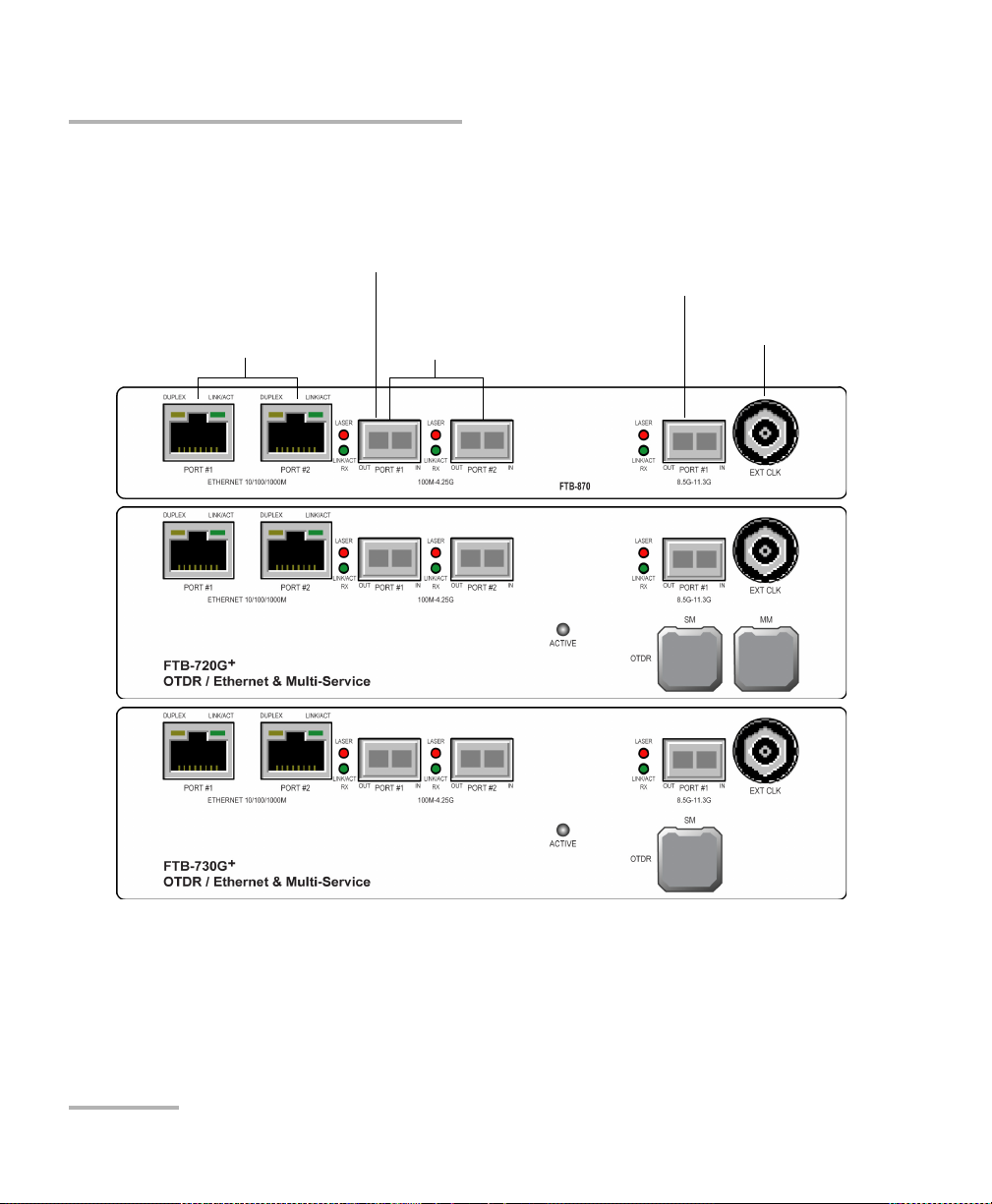
FTB-870, FTB-720G
FTB-880 Module ...................................................................................................................13
Port Availability on the NetBlazer Modules ...........................................................................14
100M-4.25G (PORT #1/#2) ..................................................................................................16
8.5G-11.3G (PORT #1) ..........................................................................................................17
155M-2.5G (PORT #1) ..........................................................................................................18
10G (PORT #1) .....................................................................................................................19
ETHERNET 10G (PORT #1) .....................................................................................................20
ETHERNET 100/1000M (PORT #1/#2) ...................................................................................21
ETHERNET 10/100/1000M .....................................................................................................22
2M-155M (PORT #1) ............................................................................................................22
2M-52M (PORT #2) ..............................................................................................................22
1.5M/2M (PORT #1/#2) ........................................................................................................22
Headset/Microphone Port (FTB-1) .........................................................................................23
AUX Connection ...................................................................................................................23
Fibre Cables Connection .......................................................................................................23
EXT CLK ...............................................................................................................................24
LEDs ......................................................................................................................................24
+
, and FTB-730G+ Modules ....................................................................12
NetBlazer v
Page 6

5 Graphical User Interface Overview ............................................................25
Main Application Window ...................................................................................................25
Main Window .......................................................................................................................25
Navigation Buttons ...............................................................................................................25
Status Bar ............................................................................................................................26
Title Bar ...............................................................................................................................28
Global Indicator ....................................................................................................................29
Test Control .........................................................................................................................32
Test Menu ............................................................................................................................32
Application Buttons .............................................................................................................32
Zoomed-In/Zoomed-Out Views .............................................................................................35
Arrow Buttons .....................................................................................................................35
Keyboard Usage ...................................................................................................................36
6 Test Setup - Test Applications ...................................................................39
OTN BERT ..............................................................................................................................40
SONET/SDH BERT .................................................................................................................42
DSn/PDH BERT ......................................................................................................................45
SONET/SDH - DSn/PDH BERT ...............................................................................................47
NI/CSU Emulation ................................................................................................................50
ISDN PRI ...............................................................................................................................51
EtherSAM (Y.1564) ...............................................................................................................52
RFC 2544 ..............................................................................................................................53
EtherBERT .............................................................................................................................54
Traffic Gen & Mon ...............................................................................................................55
Smart Loopback ....................................................................................................................56
Through Mode .....................................................................................................................58
TCP Throughput ...................................................................................................................59
Carrier Ethernet OAM .........................................................................................................60
Cable Test ............................................................................................................................61
1588 PTP ..............................................................................................................................62
SyncE ...................................................................................................................................63
FC BERT ...............................................................................................................................64
CPRI/OBSAI BERT .................................................................................................................65
7 Selecting and Starting a Test .....................................................................67
Transport Test Applications ...................................................................................................67
Ethernet Test Applications ....................................................................................................69
Packet Sync Test Applications ................................................................................................71
Fibre Channel Test Application ..............................................................................................73
Wireless Test Application ......................................................................................................74
vi FTB-700G/800 Series
Page 7

8 Test Setup - Test Configurator, Timer, and System .................................. 77
Test Configurator Overview ..................................................................................................81
Modify Structure Button ......................................................................................................84
Signal Auto-Detect ..............................................................................................................95
1588 PTP .............................................................................................................................96
BERT ..................................................................................................................................101
Cable Test .........................................................................................................................107
SFP/SFP+ ...........................................................................................................................109
Clock ...................................................................................................................................110
EtherBERT and Unframed BERT ..........................................................................................114
EtherSAM - Burst ..............................................................................................................118
EtherSAM - Global ............................................................................................................120
EtherSAM - Ramp .............................................................................................................124
FTFL/PT ................................................................................................................................126
Global (Fibre Channel) ......................................................................................................130
Interface (Ethernet) .............................................................................................................133
Interface - Port (Fibre Channel) .........................................................................................139
ISDN PRI - Call Management .............................................................................................143
ISDN PRI - ISDN Settings ...................................................................................................148
Labels ................................................................................................................................150
MAC/IP/UDP .......................................................................................................................151
Network ............................................................................................................................164
RFC 2544 - Global .............................................................................................................169
RFC 2544 - Subtests ..........................................................................................................172
S-OAM ..............................................................................................................................181
Services - Global ...............................................................................................................188
Services - Profile ................................................................................................................191
Signal (Transport) ..............................................................................................................198
Signal - Signal Configuration (DSn/PDH) ............................................................................204
Signal - Signal Configuration (OTN) ....................................................................................212
Signal - Signal Configuration (SONET/SDH) ........................................................................214
Smart Loopback .................................................................................................................218
Streams - Global ...............................................................................................................220
Streams - Profile ................................................................................................................222
SyncE ................................................................................................................................229
System ................................................................................................................................231
TCP Throughput ................................................................................................................232
Timer ..................................................................................................................................234
Traces (OTN) .......................................................................................................................236
Traces (SONET/SDH) ...........................................................................................................239
NetBlazer vii
Page 8

9 Test Results ................................................................................................241
Alarms/Errors Overview .......................................................................................................244
Alarms/Errors .....................................................................................................................246
FTFL/PT ................................................................................................................................298
Graph (RFC 2544) ...............................................................................................................300
ISDN Logger ......................................................................................................................301
Labels ................................................................................................................................306
Logger and Alarms/Errors Logger ......................................................................................307
MPLS ................................................................................................................................309
Performance Monitoring ....................................................................................................310
PTP Stats ...........................................................................................................................317
Quality Level (1588 PTP) ...................................................................................................319
Quality Level (SyncE) .........................................................................................................321
S-OAM ..............................................................................................................................324
Service Configuration - Burst ............................................................................................328
Service Configuration - Ramp ...........................................................................................329
Service Performance .........................................................................................................330
Streams - Frame Loss / Out-of-Sequence ...........................................................................332
Streams - Jitter ..................................................................................................................332
Streams - Latency .............................................................................................................333
Streams - Throughput .......................................................................................................334
Summary ...........................................................................................................................335
Summary (1588 PTP) ........................................................................................................339
Summary (Cable Test) .......................................................................................................343
Summary (EtherSAM) .......................................................................................................347
Summary (FC BERT) ............................................................................................................350
Summary (ISDN PRI) ..........................................................................................................352
Summary (NI/CSU Emulation) ............................................................................................358
Summary (RFC 2544) ........................................................................................................359
Summary (S-OAM) ............................................................................................................362
Summary (SyncE) ..............................................................................................................366
Summary (TCP Throughput) ..............................................................................................368
Summary (Traffic Gen & Mon) ...........................................................................................371
Traces - OTN .......................................................................................................................373
Traces - SONET/SDH ...........................................................................................................375
Traffic - Ethernet ................................................................................................................376
Traffic - Flow Control .........................................................................................................378
Traffic - Graph ...................................................................................................................380
Traffic - S-OAM .................................................................................................................381
WIS ...................................................................................................................................383
viii FTB-700G/800 Series
Page 9

10 Test Functions ........................................................................................... 385
APS ....................................................................................................................................388
FDL - Bit-Oriented Message ................................................................................................392
FDL - Performance Report Message ...................................................................................398
FEAC ..................................................................................................................................401
Filters and Packet Capture - Filters .....................................................................................406
Filters and Packet Capture - Packet Capture .......................................................................410
OH - OTN ............................................................................................................................416
OH - SONET/SDH ................................................................................................................422
Ping & Trace Route ..............................................................................................................436
Pointer Adjustment ............................................................................................................441
RTD .....................................................................................................................................454
S-OAM Link Trace ..............................................................................................................457
Signaling Bits .....................................................................................................................459
Spare Bits ...........................................................................................................................460
11 Test Control .............................................................................................. 463
More/Less Button ................................................................................................................463
Discover Remote Button ...................................................................................................464
Headset/DTMF Button .......................................................................................................467
Inject Button .......................................................................................................................469
Laser Button .......................................................................................................................469
Lpbk Tool Button (Loopback Tool) .....................................................................................470
Phone Book Button ...........................................................................................................477
Report Button ....................................................................................................................481
Reset Button .......................................................................................................................485
Save/Load Button ...............................................................................................................486
Start/Stop Button ................................................................................................................492
12 Power Failure Recovery ............................................................................ 493
Automatic Power Failure Recovery ......................................................................................493
Manual Power Failure Recovery ..........................................................................................493
When Using the Test Timer .................................................................................................494
13 Suspend and Resume ............................................................................... 495
Suspend Mode ....................................................................................................................495
Resume Operation ..............................................................................................................496
14 Maintenance ............................................................................................. 497
Cleaning LC Connectors ......................................................................................................498
Recalibrating the Unit .........................................................................................................499
Recycling and Disposal (Applies to European Union Only) ..................................................500
NetBlazer ix
Page 10

15 Troubleshooting ........................................................................................501
Solving Common Problems .................................................................................................501
Contacting the Technical Support Group ............................................................................502
Transportation ....................................................................................................................502
16 Warranty ....................................................................................................503
General Information ...........................................................................................................503
Liability ...............................................................................................................................504
Exclusions ...........................................................................................................................504
Certification ........................................................................................................................504
Service and Repairs .............................................................................................................505
EXFO Service Centers Worldwide ........................................................................................506
17 Specifications ............................................................................................507
General Specifications ........................................................................................................507
SFP SONET/SDH and OTN Optical Interfaces ........................................................................508
SFP+ 10G SONET/SDH and OTN Optical Interfaces .............................................................509
DSn/PDH and SONET/SDH Electrical Interfaces ....................................................................510
SFP CPRI/OBSAI Optical Interface ........................................................................................511
SFP Ethernet Optical Interfaces ...........................................................................................512
SFP+ Ethernet Optical Interfaces ........................................................................................513
Ethernet Electrical Interfaces ..............................................................................................514
SFP Fibre Channel Interfaces ...............................................................................................515
SFP+ Fibre Channel Interfaces ............................................................................................516
Synchronization Interface ..................................................................................................517
18 Glossary .....................................................................................................519
Acronym List .......................................................................................................................519
10G Ethernet Client ............................................................................................................535
1588 PTP .............................................................................................................................538
Ethernet Cables .................................................................................................................543
G.709 Optical Transport Network (OTN) ............................................................................545
MPLS Labels ........................................................................................................................561
SONET/SDH .........................................................................................................................562
SyncE ..................................................................................................................................572
Unicast/Multicast Addresses for S-OAM ..............................................................................574
VLAN ID and Priority ...........................................................................................................575
Index ...............................................................................................................577
x FTB-700G/800 Series
Page 11

1 Introducing the Ethernet and
Multiservice Tester
ALL-IN-ONE Ethernet/optical solution for field technicians installing, testing
and troubleshooting FTTx, fronthaul, backhaul, small-cell, DAS, remote
radio head and data center networks, in addition to OTN, SONET/SDH,
Fibre Channel, GigE and 10 GigE, CPRI/OBSAI and SyncE/1588 PTP
services, with the added support of OTDR and iOLM capabilities.
Features
Modules
Features
860GL
Ethernet
Fibre Channel
1588 PTP and SyncE
CPRI & OBSAI
OTN
SONET/SDH
DSn/PDH
ISDN PRI and NI/CSU
OTDR and iOLM
860
860G
XXXX XX
720G
730G
XXX XX
XXX XX
XXX XX
730G+
730G+
XX
810G
XXX
XXXX
810
870 880
XX
XX
NetBlazer 1
Page 12

Introducing the Ethernet and Multiservice Tester
Conventions
Conventions
Before using the product described in this guide, you should understand
the following conventions:
WARNING
Indicates a potentially hazardous situation which, if not avoided,
could result in death or serious injury. Do not proceed unless you
understand and meet the required conditions.
CAUTION
Indicates a potentially hazardous situation which, if not avoided,
may result in minor or moderate injury. Do not proceed unless you
understand and meet the required conditions.
CAUTION
Indicates a potentially hazardous situation which, if not avoided,
may result in component damage. Do not proceed unless you
understand and meet the required conditions.
IMPORTANT
Refers to information about this product you should not overlook.
2 FTB-700G/800 Series
Page 13

2 Safety Information
WARNING
Do not install or terminate fibers while a light source is active.
Never look directly into a live fiber and ensure that your eyes are
protected at all times.
WARNING
The use of controls, adjustments and procedures, namely for
operation and maintenance, other than those specified herein may
result in hazardous radiation exposure or impair the protection
provided by this unit.
IMPORTANT
When you see the following symbol on your unit , make sure
that you refer to the instructions provided in your user
documentation. Ensure that you understand and meet the required
conditions before using your product.
IMPORTANT
Other safety instructions relevant for your product are located
throughout this documentation, depending on the action to
perform. Make sure to read them carefully when they apply to your
situation.
NetBlazer 3
Page 14

Safety Information
Additional Laser Safety Information
Additional Laser Safety Information
This product employs Class 1 Laser SFP/SFP+. Refer to the FTB-700 Series
user guide for additional laser safety information.
WARNING
When the LASER LED is on or flashing, the FTB-700G/800 Series is
transmitting an optical signal on the SFP/SFP+ transceiver ports.
Note: Refer to the FTB-1’s user guide for additional test equipment safety
information and ratings.
4 FTB-700G/800 Series
Page 15

Safety Information
Installation Instruction Warnings
Installation Instruction Warnings
CAUTION
When you use the unit outdoors, ensure that it is protected from
liquids, dust, direct sunlight, precipitation, and full wind pressure.
CAUTION
Except for the Dual Bantam connector and the RJ-48C port, all
telecom (electrical) interfaces are SELV (Safety Extra Low Voltage)
circuitry intended for intra-building use only.
CAUTION
For the Dual Bantam connector and the RJ-48C ports, use only No.
26 AWG or larger telecommunication line cord to reduce the risk of
fire.
CAUTION
No user serviceable parts are contained inside. Contact the
manufacturer regarding service of this equipment.
IMPORTANT
All wiring and installation must be in accordance with local building
and electrical codes acceptable to the authorities in the countries
where the equipment is installed and used.
NetBlazer 5
Page 16

Safety Information
Installation Instruction Warnings
Electrostatic Discharge (ESD) Sensitive Equipment:
Plug-in modules can be damaged by static electrical discharge. To
minimize the risk of damage, dissipate static electricity by touching
a grounded unpainted metal object
before removing, inserting or handling the module
before connecting or disconnecting cables to/from the module.
before inserting or removing SFP/SFP+ transceiver to/from the
module.
CAUTION
6 FTB-700G/800 Series
Page 17

3 Getting Started
If the FTB-700G/800 Series has been purchased at the same time as the
FTB-1, the FTB-700G/800 Series module is pre-installed with the
appropriate software version. If the NetBlazer and OTDR is not already
installed, refer to the FTB-1 User Guide for more information on how to
install the module.
Turning On the Unit
Turn on the FTB-1. Refer to the FTB-1 platform user guide for more
information.
Starting the Module Application
The module can be configured and controlled by starting the NetBlazer or
an OTDR application.
To start the NetBlazer application:
1. For FTB-800 Series, from Mini ToolBox tap the application button.
2. For FTB-700G Series, from Mini ToolBox select the
FTB-7xx Ethernet & Multi-Service module then tap NetBlazer
application button. Only one application can run at once, either
NetBlazer or one OTDR application.
Note: To start an OTDR application, refer to the FTB-700 Series user guide for
more information.
3. Fo r the Restore Default prompt, tap Yes to restore the factory default
settings or No to preserve the settings from the last shut down. If the
user does not tap any button within 10 seconds the NetBlazer
application uses the settings from the last shut down. Select the
Disable Reminder check box to disable the display of this pop-up
every time the NetBlazer application is launched and to use the
settings from the last shut down. Refer to Save/Load tab on page 478
for more information.
NetBlazer 7
Page 18

Page 19
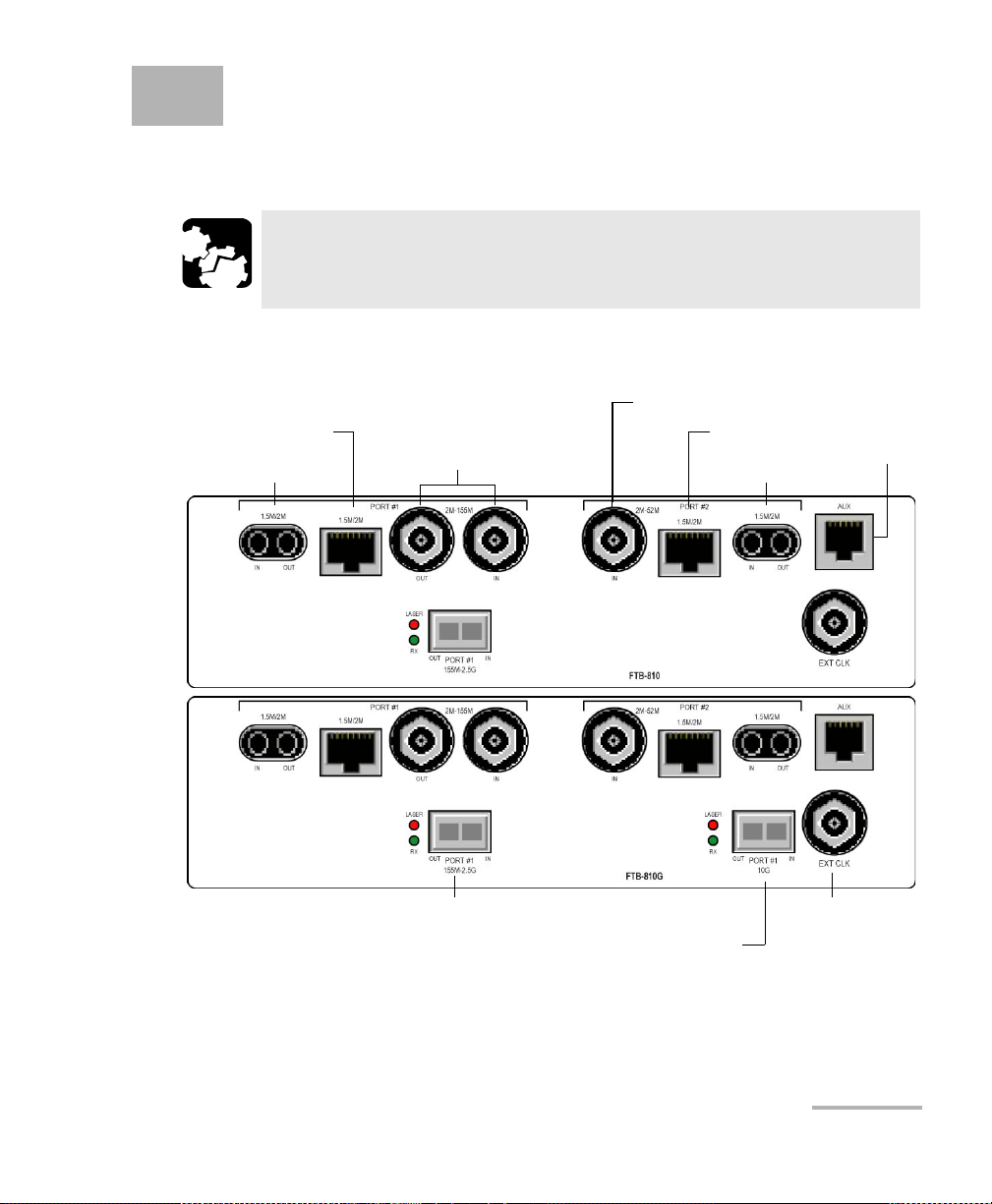
4 Physical Interfaces and LEDs
E1/2M, E3/34M, DS3/45M,
STS-1e/STM-0e/52M, E4/140M,
STS-3e/STM-1e/155M
DS1/1.5M RX
DS1/1.5M, E1/2M
DS3/45M RX
DS1/1.5M RX
DS1/1.5M, E1/2M
AUX
External IN/OUT
Clock
DS1/E1/2MHz/1PPS
OC-1/STM-0, OC-3/STM-1, OC-12/STM-4, OC-48/STM-16
1
OC-192/STM-64
1
1. Laser radiation emitted from this port when LASER LED is on.
This section describes all connectors (ports) and LEDs available on the
FTB-700G/800 Series module.
CAUTION
To prevent exceeding the maximum input/output power level,
please refer to the Specifications on page 507.
FTB-810 and FTB-810G Modules
NetBlazer 9
Page 20
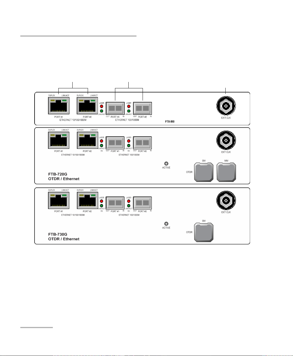
Physical Interfaces and LEDs
Ethernet 10/100/1000 Mbit/s
Ethernet 100/1000 Mbit/s
1
,
CPRI/OBSAI 2.4576/3.072 Gbit/s
1
,
Fibre Channel 1X/2X/4X
1
External IN/OUT Clock
DS1/E1/2MHz/1PPS
1. Laser radiation emitted from this port when LASER LED is on.
FTB-860, FTB-720G, and FTB-730G Modules
FTB-860, FTB-720G, and FTB-730G Modules
10 FTB-700G/800 Series
Page 21
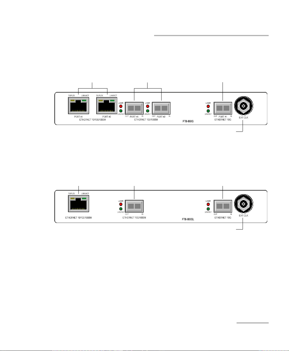
FTB-860G Module
Ethernet 10/100/1000 Mbit/s
Ethernet 100/1000 Mbit/s
1
,
CPRI/OBSAI 2.4576/3.072 Gbit/s
1
,
Fibre Channel 1X/2X/4X
1
External IN/OUT Clock
DS1/E1/2MHz/1PPS
Ethernet 10 Gbit/s1,
Fibre Channel 8X/10X
1
1. Laser radiation emitted from this port when LASER LED is on.
Ethernet 10/100/1000 Mbit/s Ethernet 100/1000 Mbit/s
1
External IN/OUT Clock
DS1/E1/2MHz/1PPS
Ethernet 10 Gbit/s
1
1. Laser radiation emitted from this port when LASER LED is on.
FTB-860GL Module
Physical Interfaces and LEDs
FTB-860G Module
NetBlazer 11
Page 22
Physical Interfaces and LEDs
External IN/OUT Clock
DS1/E1/2MHz/1PPS
Ethernet 100/1000 Mbit/s1,
CPRI/OBSAI 2.4576/3.072 Gbit/s
1
,
Fibre Channel 1X/2X/4X
1
OC-192/STM-641,
OTU2, OTU1e, OTU2e, OTU1f, OTU2f
1
,
Ethernet 10 Gbit/s
1
,
Fibre Channel 8X/10X
1
Ethernet 10/100/1000 Mbit/s
OC-1/STM-0, OC-3/STM-11,
OC-12/STM-4, OC-48/STM-16
1
,
OTU1
1
1. Laser radiation emitted from this port when LASER LED is on.
FTB-870, FTB-720G+, and FTB-730G+ Modules
FTB-870, FTB-720G+, and FTB-730G+ Modules
12 FTB-700G/800 Series
Page 23
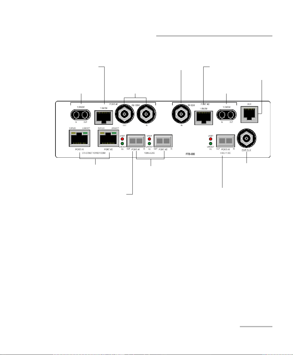
FTB-880 Module
External IN/OUT Clock
DS1/E1/2MHz/1PPS
Ethernet 100/1000 Mbit/s
1
,
CPRI/OBSAI 2.4576/3.072 Gbit/s
1
,
Fibre Channel 1X/2X/4X
1
OC-192/STM-641,
OTU2, OTU1e, OTU2e, OTU1f, OTU2f
1
,
Ethernet 10 Gbit/s
1
,
Fibre Channel 8X/10X
1
E1/2M, E3/34M, DS3/45M,
STS-1e/STM-0e/52M, E4/140M,
STS-3e/STM-1e/155M
DS1/1.5M RX
DS1/1.5M, E1/2M
DS3/45M RX
DS1/1.5M RX
DS1/1.5M, E1/2M
AUX
Ethernet 10/100/1000 Mbit/s
OC-1/STM-0, OC-3/STM-11,
OC-12/STM-4, OC-48/STM-16
1
,
OTU1
1
1. Laser radiation emitted from this port when LASER LED is on.
Physical Interfaces and LEDs
FTB-880 Module
NetBlazer 13
Page 24

Physical Interfaces and LEDs
Port Availability on the NetBlazer Modules
Port Availability on the NetBlazer Modules
The following table shows the list of available ports as well as a description
and signals supported for each module.
Port labelled Description and Supported signal(s) Module
1.5M/2M
(PORT #1)
2M-155M
(PORT #1)
1.5M/2M
(PORT #2)
2M/52M
(PORT #2)
155M-2.5G
(PORT #1)
100M-4.25
(PORT #1)
(PORT #2)
8.5G-11.3G
(PORT #1)
Electrical IN/OUT port Bantam
DS1/1.5M, E1/2M
Electrical IN/OUT port RJ-48C
DS1/1.5M, E1/2M
Electrical IN/OUT ports BNC
E1/2M, E3/34M, DS3/45M, STS-1e/STM-0e/52M, E4/140M,
STS-3e/STM-1e/155M
Electrical IN port Bantam
DS1/1.5M
Electrical IN port RJ-48C
DS1/1.5M
Electrical IN port BNC
DS3/45M
Optical IN/OUT port SFP
OC-1/STM-0, OC-3/STM-1, OC-12/STM-4, OC-48/STM-16
Optical IN/OUT ports SFP
OC-1/STM-0, OC-3/STM-1, OC-12/STM-4, OC-48/STM-16,
b
OTU1
Ethernet 100 Mbit/s, Ethernet 1000 Mbit/s
CPRI/OBSAI 2.4576/3.072 Gbit/s (optical)
Fibre Channel 1X/2X/4X
Optical IN/OUT port SFP+
OC-192/STM-64, OTU2, OTU1e, OTU2e, OTU1f, OTU2f
Ethernet 10 Gbit/s
Fibre Channel 8X/10X
FTB-810/810G/
880
FTB-810/810G
FTB-720G
+
730G
FTB-720G
+
730G
+
/
/870/880
+
/
/870/880
14 FTB-700G/800 Series
Page 25

Physical Interfaces and LEDs
Port Availability on the NetBlazer Modules
Port labelled Description and Supported signal(s) Module
10G
(PORT #1)
Optical IN/OUT port SFP+
OC-192/STM-64
FTB-810G
AUX Future use FTB-810/
810G/880
ETHERNET
10/100/1000M
(PORT #1 and
PORT #2)
ETHERNET
100/1000M
(PORT #1 and
PORT #2)
Electrical Ethernet port RJ-45:
Ethernet 10/100/1000 Mbit/s (electrical)
Optical IN/OUT port small form factor pluggable (SFP):
Ethernet 100 Mbit/s (optical), Ethernet 1000 Mbit/s
(optical)
CPRI/OBSAI 2.4576/3.072 Gbit/s (optical)
b
FTB-720G/
+
/730G/
720G
+
/860/
730G
860G/860GL
FTB-720G/
730G/860/
860G/860GL
Fibre Channel 1X/2X/4X
ETHERNET
10G
(PORT #1)
Optical IN/OUT port 10G small form factor pluggable
(SFP+):
Ethernet 10 Gbit/s
FTB-860G/
a
860GL
Fibre Channel 8X/10X
EXT CLK Electrical port BNC for external clock synchronization:
All
DS1/1.5M/E1/2M/2 MHz/1PPS
a
a
/
a. Only one port is available on the FTB-860GL module. The FTB-860GL module does not support Fibre
Channel and CPRI/OBSAI test applications.
b. OC-x/STM-x/OTU1 and CPRI/OBSAI are only available on PORT #1.
NetBlazer 15
Page 26

Physical Interfaces and LEDs
100M-4.25G (PORT #1/#2)
100M-4.25G (PORT #1/#2)
The 100M-4.25G PORT #1 can be used for optical Transport, Ethernet, Fibre
Channel, or Packet Sync test applications.
The 100M-4.25G PORT #2 is only used for optical Ethernet, Fibre Channel,
and Packet Sync test applications.
Supported rates:
For Transport Optical Interface (OTN/OC-N/STM-N): OC-1/STM-0,
OC-3/STM-1, OC-12/STM-4, OC-48/STM-16, OTU1
Plug the SFP module into the SFP/SFP+ PORT #1 slot on the module.
For Ethernet, Packet Sync, and Fibre Channel Optical Interface:
100Mbit/s, 1000 Mbit/s, 10Gbit/s, CPRI/OBSAI 2.4576/3.072 Gbit/s, Fibre
Channel 1X/2X/4X.
Plug the SFP module into the 100M-4.25G PORT #1 or PORT #2 slot on the
module.
Note: Use only EXFO supported transceivers. Refer to the Specifications on
page 507 for the list of supported transceivers. Using non-supported
transceivers can affect the performance and accuracy of the test.
Note: Do not replace a SFP/SFP+ while the test is running to avoid distorting
statistics. First stop the test case, replace the SFP/SFP+ and then restart the
test.
16 FTB-700G/800 Series
Page 27

Physical Interfaces and LEDs
8.5G-11.3G (PORT #1)
8.5G-11.3G (PORT #1)
The 8.5G-11.3G PORT #1 can be used for optical Transport, Ethernet, Fibre
Channel, or Packet Sync test applications.
Supported rates:
For Transport Optical Interface: OC-192/STM-64, OTU2, OTU1e, OTU2e,
OTU1f, and OTU2f.
For Ethernet Optical Interface: 10Gbit/s LAN and 10Gbit/s WAN.
For Fibre Channel Optical Interface: 8X/10X (Fibre Channel).
For Packet Sync Optical Interface: 10Gbit/s LAN.
Plug the SFP+ module into the 8.5G-11.3G PORT #1 slot on the module.
Note: Use only EXFO supported transceivers. Refer to the SFP+ 10G SONET/SDH
and OTN Optical Interfaces on page 509 for the list of supported
transceivers. Using non-supported transceivers can affect the performance
and accuracy of the test.
Note: Do not replace a SFP+ while the test is running to avoid distorting statistics.
First stop the test case, replace the SFP+ and then restart the test.
NetBlazer 17
Page 28

Physical Interfaces and LEDs
155M-2.5G (PORT #1)
155M-2.5G (PORT #1)
The 155M-2.5G PORT #1 can be used for optical Transport test
applications.
Supported rates:
OC-1/STM-0, OC-3/STM-1, OC-12/STM-4, OC-48/STM-16.
Plug the SFP module into the 8.5G-11.3G PORT #1 slot on the module.
Note: Use only EXFO supported transceivers. Refer to the SFP SONET/SDH and
OTN Optical Interfaces on page 508 for the list of supported transceivers.
Using non-supported transceivers can affect the performance and accuracy
of the test.
Note: Do not replace a SFP while the test is running to avoid distorting statistics.
First stop the test case, replace the SFP and then restart the test.
18 FTB-700G/800 Series
Page 29

Physical Interfaces and LEDs
10G (PORT #1)
10G (PORT #1)
The 10G PORT #1 can be used for optical Transport test applications.
Supported rates:
OC-192/STM-64.
Plug the SFP+ module into the 10G PORT #1 slot on the module.
Note: Use only EXFO supported transceivers. Refer to the SFP+ 10G SONET/SDH
and OTN Optical Interfaces on page 509 for the list of supported
transceivers. Using non-supported transceivers can affect the performance
and accuracy of the test.
Note: Do not replace a SFP+ while the test is running to avoid distorting statistics.
First stop the test case, replace the SFP+ and then restart the test.
NetBlazer 19
Page 30

Physical Interfaces and LEDs
ETHERNET 10G (PORT #1)
ETHERNET 10G (PORT #1)
The ETHERNET 10G PORT #1 can be used for optical Ethernet, and Fibre
Channel test applications.
Supported rates:
For Ethernet Optical Interface: 10 Gbit/s.
For Fibre Channel Optical Interface: 8X,10X.
Plug the SFP+ module into the ETHERNET 10G PORT #1 slot on the
module.
Note: Use only EXFO supported transceivers. Refer to the SFP+ Ethernet Optical
Interfaces on page 513 for the list of supported transceivers. Using
non-supported transceivers can affect the performance and accuracy of
the test.
Note: Do not replace a SFP+ while the test is running to avoid distorting statistics.
First stop the test case, replace the SFP+ and then restart the test.
20 FTB-700G/800 Series
Page 31

Physical Interfaces and LEDs
ETHERNET 100/1000M (PORT #1/#2)
ETHERNET 100/1000M (PORT #1/#2)
The ETHERNET 100/1000M PORT #1 can be used for optical Ethernet, Fibre
Channel, or Wireless test applications.
The ETHERNET 100/1000M PORT #2 is only used for optical Ethernet, and
Fibre Channel test applications.
Supported rates:
For Ethernet Optical Interface: 100Mbit/s, 1000 Mbit/s.
For Fibre Channel Optical Interface: 1X, 2X, 4X.
For Wireless CPRI/OBSAI Optical Interface: 2.4576, 3.072 Gbit/s.
Plug the SFP module into the ETHERNET 100/1000M PORT #1 or PORT #2
slot on the module.
Note: Use only EXFO supported transceivers. Refer to the SFP Ethernet Optical
Interfaces on page 512 for the list of supported transceivers. Using
non-supported transceivers can affect the performance and accuracy of
the test.
Note: Do not replace a SFP while the test is running to avoid distorting statistics.
First stop the test case, replace the SFP and then restart the test.
NetBlazer 21
Page 32

Physical Interfaces and LEDs
ETHERNET 10/100/1000M
ETHERNET 10/100/1000M
The ETHERNET 10/100/1000M (PORT #1 and PORT #2) can be used for
electrical Ethernet, or Packet Sync test applications.
Supported electrical rates are 10Mbits/s, 100Mbit/s, and 1000Mbit/s.
10Mbits/s is not supported for SyncE. Plug the 10/100/1000 electrical
interface or the cable to be tested to the ETHERNET 10/100/1000M (PORT
#1 or PORT #2) connector on the module. The electrical ports is RJ45 for
category 5 unshielded twisted pair (UTP). Refer to Ethernet Cables on
page 543 for cable specifications.
2M-155M (PORT #1)
This port can be used for electrical Transport test applications.
Supported electrical signal are E1/2M, E3/34M, DS3/45M,
STS-1e/STM-0e/52M, E4/140M, and STS-3e/STM-1e/155M. Plug the signal to
be tested to the BNC IN and OUT ports. Connector type is BNC for coaxial
75-ohm cable connection.
2M-52M (PORT #2)
This port can be used for electrical DS3 dual RX Transport test application.
Supported electrical signal are DS1 or DS3 for Dual RX testing capability.
Plug the signal to be tested to the BNC IN port. Connector type is BNC for
coaxial 75-ohm cable connection.
1.5M/2M (PORT #1/#2)
This port, either Bantam or RJ-48C, can be used for electrical Transport test
applications.
Supported electrical signal are DS1/1.5M and E1/2M. Plug the signal to be
tested to either Bantam or RJ48C port.
22 FTB-700G/800 Series
Page 33

Physical Interfaces and LEDs
Headset/microphone
port
Headset/Microphone Port (FTB-1)
Headset/Microphone Port (FTB-1)
CAUTION
When using speech over ISDN, ISDN PRI test application, use only
the headset supplied by EXFO to ensure adequate protection.
The headset port can be used with the ISDN PRI test application to connect
a headset allowing to speak and listen when calls are made and received.
Note: Refer to FTB-1 User Guide for instructions on configuring the
Headset/Microphone settings.
AUX Connection
The AUX port is reserved for future use to attach a buttset or telephone to
talk and listen over an ISDN PRI line.
Fibre Cables Connection
Carefully connect optical fibre cables to the SFP/SFP+’s IN and OUT ports.
To ensure good signal quality, make sure that the optical fibre connector is
fully inserted into the optical connector port.
NetBlazer 23
Page 34

Physical Interfaces and LEDs
EXT CLK
To prevent exceeding the maximum input power level please use an
attenuator when a loopback configuration is used.
EXT CLK
The FTB-700G/800 Series provides one connector, labeled EXT CLK that
can be used either for input/output external clock DS1 (1.5M), E1 (2M),
2MHz, or 1PPS synchronization signal. 1PPS is available for Dual Test Set in
One-Way Latency measurement mode. The connector type is BNC for
coaxial 75-ohm cable connection. An adapter cable (BNC to Bantam) is
required for Bantam connection (not supplied).
LEDs
LASER red LED is on when the FTB-700G/800 Series is emitting an
optical laser signal.
LINK green LED is on when the link is up, off when the link is down,
and flashing when frames are transmitted and/or received.
CAUTION
24 FTB-700G/800 Series
Page 35

5 Graphical User Interface
Main
Window
Title Bar
Te st
Control
Test M e n u
Application
Buttons
Status Bar
Global
Indicator
Navigation
Buttons
Overview
This chapter describes the FTB-700G/800 Series graphical user interface.
Main Application Window
The following main application window is displayed when the NetBlazer
application is started.
Main Window
The main window allows to setup a test and to view the test status and
results.
Navigation Buttons
Navigation buttons appear when there is not enough room on one page to
display all available test applications. The left and right arrow buttons allow
to respectively access the previous or next window. The buttons in
between the left and right arrow buttons allow to directly select the
window for the type of test application listed.
NetBlazer 25
Page 36

Graphical User Interface Overview
Status Bar
Status Bar
The status bar displays the following information.
Icon and/or
text
Description
Test
Application
Test ico n Test ic o n o f the test . All
P1, P2 Port number (Port 1 or Port 2) Ethernet
TX/RX, TX,
Indicates the direction of the signal per port. Transport
RX
Interface/
Signal
LINK Green arrow: Ethernet Link up
PTP Green arrow: Signaling requests granted.
The interface or signal rate per port:1GE Optical, OTU1,
OTU2, etc.
Red arrow: Ethernet Link down.
All
Transport
Ethernet
1588 PTP
Red arrow: Request denied, session canceled, or no reply.
Gray arrow: Pending or inactive.
Refer to Negotiation Status on page 340 for more
information.
ESMC Green arrow: ESMC valid information frame received.
SyncE
Red arrow: No ESMC valid information frames received.
Gray arrow: Pending state.
Refer to ESMC Monitoring on page 229 for more
information.
D-Channel The channel used as the D-channel to transmit signalling
ISDN PRI
information.
Green arrow: Link up
Red arrow: Link down.
B-Channel #x is configured as a Speech or 3.1 kHz
ISDN PRI
channel
26 FTB-700G/800 Series
Page 37

Graphical User Interface Overview
Status Bar
Icon and/or
text
Description
Power Level The received signal level per port in dBdsx for DSn signal
or dBm for PDH and optical signals. For Transport electrical
interface, LOS on red background indicates that there is no
electrical signal power. For optical interface, the following
background color are used as power level qualifier:
Green: Power level in range.
Yellow: Power level out-of-range.
Red with “LOS”: Loss of signal.
Red with “Power”: Power level is close to damage.
Gray: Invalid operational range value.
Amplitude Amplitude indicates the received signal amplitude per port.
Only available with electrical interfaces.
Laser ON. The laser icon is not displayed when the laser is
off. The laser icon is only displayed for optical interfaces.
The laser is ON by default when the test is created. The
laser control is not affected when turning off the laser by
generating a LOS for example. Refer to Laser Button on
page 469.
The status of the received signal pattern per port using the
following background colors.
Green: Pattern is synchronized.
Red: Loss of pattern.
Gray: Test is not running (EtherBERT test) or the RX Pattern
Analysis check box is cleared.
Test
Application
All except
for Cable
Tes t
Transport
All
Transport
and
EtherBERT
A connection is established between two testing units
Ethernet
either in Dual Test Set (DTS) or in Loop Up mode.
Loopback Tool enabled on the port unused by the main
Ethernet
test application.
NetBlazer 27
Page 38

Graphical User Interface Overview
Title Bar
Icon and/or
text
Description
Clock synchronization signal clock. The clock icon is
followed by the clock mode: INT for Internal, EXT for
External, or RCV for Recovered.
Application
Transport
and
Ethernet
Green: Clock Synchronized.
Red: Loss of clock.
Indicates a manual change in the OH bytes transmitted.
Transport
Not displayed when using the default OH values.
The test is in loopback mode. Not displayed when not in
loopback mode.
Alarm/error is currently injected. Not displayed when there
is no alarm/error injection.
NI-CSU
Emulation
Transport,
EtherBERT,
Carrier
Ethernet
OAM, and
CPRI/OBSAI
BERT
The following status are available at the platform level.
Battery/AC icons indicate the battery level and if the FTB-1 is
connected to an AC power source. Refer to the FTB-1 user guide for
more information.
Test
Date and Time indicate the current date and time.
Title Bar
The Title Bar displays the software application name and the battery level
indicator.
28 FTB-700G/800 Series
Page 39

Global
Alarm
Graphical User Interface Overview
Global Indicator
Global Indicator
The global indicator area displays the pass/fail verdict, global alarm, and
the test duration.
Global indicator area
Global
Verdict
Current
History
Te s t T i m e r
The global indicator area can be maximized for distant viewing. Tap
anywhere within the global indicator area to display a maximized view. Tap
again to exit the maximized view.
NetBlazer 29
Page 40

Graphical User Interface Overview
Global Indicator
Global Verdict
Reports the global test verdict status when supported by the test
application and enabled (when applicable).
PASS is displayed with a green background when all result values meet
the configured threshold criteria.
FAI L is displayed with a red background when any result value does
not meet the configured threshold criteria or when a specific alarm is
detected (refer to each test application for additional information).
“--” is displayed with a gray background when at least one of the
following conditions is met:
- Pass/Fail verdict is not enabled
- there is no defined criterion
- the test has not run yet.
30 FTB-700G/800 Series
Page 41

Graphical User Interface Overview
Global Alarm
Indicates the current and history alarm/error status of the test.
Global Indicator
Background
color
Alarm/
Error
Tex t
displayed
Description
Gray Current -- No test result available.
History
Green Current No Alarm No alarm/error has occurred in the
last second.
History No alarm/error has occurred during
the test.
Red Current Alarms or
the name of
An alarm/error occurred in the last
second.
the alarm.
History
Amber History No current alarm/error but at least
one alarm/error has occurred during
the test.
Test Tim er
The test timer without the timer icon indicates the time elapsed since the
beginning of the test. No timer action is active. The test timer format is “day
hour:minute:second”.
Timer
The timer icon with Armed indicates that a start time is active.
The timer icon with the Test Timer indicates that a duration and/or a stop
time is active.
NetBlazer 31
Page 42

Graphical User Interface Overview
Test Control
Test Control
Note: Refer to Test Con t r o l on page 463 for more information.
Test Menu
The test menu displays the following buttons:
Setup allows to configure the selected test. Refer to Test Set u p - Te s t
Configurator, Timer, and System on page 77 for more information.
Results allows to view test results. Refer to Test Results on page 241 for
more information.
Functions allows to configure additional test functions (refer to Te st
Funct ions on page 385).
Application Buttons
Help (?) displays the help information related to the content of the
active main window. It is also possible to navigate through the
remainder of the help information.
Exit (x) closes the application.
About (i) mainly displays the product version details and technical
support information.
Module Details button displays module details such as its ID, Serial
Number, Software Product Version, etc.
View Licence Agreement button displays the details of the product
licence agreement.
Software Options button displays the list of software options.
32 FTB-700G/800 Series
Page 43

Graphical User Interface Overview
Application Buttons
Note: For information on how to install and activate software options, refer to the
FTB-1 User Guide. The module application must be restarted once a new
software option is installed in order to activate it.
Following is the list of available software options:
Options Description
DSn Digital Signal
DS1-FDL DS1/1.5M Facility Data Link
DS3-FEAC DS3/45M Far-End Alarm and Control
DUALRX Dual RX
DS3-G747 ITU-T Recommendation G.747
PDH Plesiochronous Digital Hierarchy
NI-CSU NI/CSU Emulation
SONET Synchronous Optical Network
SDH Synchronous Digital Hierarchy
TCM Tandem Connection Monitoring
52M 52 Mbit/s
155M 155 Mbit/s
622M 622 Mbit/s
2488M 2.488 Gbit/s
9953M 9.953 Gbit/s
100optical 100 Mbit/s optical interfaces.
GigE _Optical 1000Base-T and GigE optical interfaces.
GigE_ Electrical 1000Base-T electrical Interfaces.
10G_LAN 10G LAN optical interface.
10G_WAN 10G WAN optical interface.
NetBlazer 33
Page 44

Graphical User Interface Overview
Application Buttons
Options Description
FC-1X Fibre Channel 1X
FC-2X Fibre Channel 2X
FC-4X Fibre Channel 4X
FC-8X Fibre Channel 8X
FC-10X Fibre Channel 10X
IPV6 IPV6 testing.
MPLS MPLS Encapsulation
TRAFFIC _GEN Traffic Gen & Mon test application
Cable_Test Cable Test application
TCP-THPUT TCP Throughput Test Application
CPRI CPRI
OBSAI OBSAI
1588PTP 1588 Precision Time Protocol Test Application
SyncE Synchronous Ethernet Test Application
ETH-THRU Through Mode test application.
ETH-OAM Carrier Ethernet OAM test application
ETH-CAPTURE Ethernet Frame Capture
ADV-FILTERS Advanced filtering
34 FTB-700G/800 Series
Page 45

Graphical User Interface Overview
Moves to the top of the list.
Moves one page up.
Moves one line up.
Moves one line down.
Moves one page down.
Moves to the end of the list.
Zoomed-In/Zoomed-Out Views
Zoomed-In/Zoomed-Out Views
Some configuration and result blocks give access to zoomed views
allowing more detailed configurations/results.
The block title contains the magnifier (+) icon when a zoomed view is
available.
To zoom-in, tap the magnifier (+) icon or anywhere on the block.
To zoom-out, tap on the magnifier (-) icon or anywhere on the block title.
Arrow Buttons
NetBlazer 35
Page 46

Graphical User Interface Overview
Keyboard Usage
Keyboard Usage
The GUI pops up different keyboards to modify data. Following are the
usual keyboard keys:
Left arrow moves the cursor one position to the left.
Right arrow moves the cursor one position to the right.
Up arrow increases the value by one.
Down arrow decreases the value by one.
Del deletes the value at the cursor position.
Back deletes the value preceding the cursor position.
OK completes data entry.
Cancel closes the keyboard and discards the keyboard entry.
Previous... allows the selection of previously configured values. This
button is only available for certain fields like IP Address, MAC Address,
etc.
Note: For certain text fields, the GUI pops up or uses the platform’s on-screen
keyboard. Refer to the platform user guide for more information on how to
used it.
For full keyboard, the Back, Del, Shift, and Space bar keys have the same
functionality as a regular PC keyboard.
36 FTB-700G/800 Series
Page 47

Graphical User Interface Overview
Keyboard Usage
For multiplexing keyboard, tap on all mapped signals that have to be
added/removed to/from the test path.
A mapped signal with an orange background color is part of the test
path.
A mapped signal with a gray background color is not part of the test
path.
NetBlazer 37
Page 48

Graphical User Interface Overview
Keyboard Usage
The Trace message keyboard allows entering alphanumerical characters
(ITU T.50) required for Trace fields. Tap the Control Characters button to
access these characters.
ITU T.50 Characters
b7 to b1 Character Description b7 to b1 Character Description
000 0000 NUL Null 001 0000 DLE Data Link Escape
000 0001 SOH Start Of Heading 001 0001 DC1 Device Control 1
000 0010 STX Start of Text 001 0010 DC2 Device Control 2
000 0011 ETX End of Text 001 0011 DC3 Device Control 3
000 0100 EOT End Of
001 0100 DC4 Device Control 4
Transmission
000 0101 ENQ Enquiry 001 0101 NAK Negative Acknowledge
000 0110 ACK Acknowledge 001 0110 SYN Synchronous idle
000 0111 BEL Bell 001 0111 ETB End of Transmission
Block
000 1000 BS Backspace 001 1000 CAN Cancel
000 1001 HT Horizontal
001 1001 EM End of Medium
Tab ul at ion
000 1010 LF Line Feed 001 1010 SUB Substitute character
000 1011 VT Vertical Tabulation 001 1011 ESC Escape
000 1100 FF Form Feed 001 1100 IS4 Information Separator 4
000 1101 CR Carriage Return 001 1101 IS3 Information Separator 3
000 1110 SO Shift-Out 001 1110 IS2 Information Separator 2
000 1111 SI Shift-In 001 1111 IS1 Information Separator 1
38 FTB-700G/800 Series
Page 49

6 Test Setup - Test Applications
The NetBlazer offers the following test applications.
Available on FTB-...
Type Application
Tran spor t OTN BERT ---XX40
SONET/SDH BERT -X- XX42
DSn/PDH BERT -X- -X45
SONET/SDH - DSn/PDH BERT -X- -X47
NI/CSU Emulation -X- -X50
ISDN PRI -X- X51
Ethernet EtherSAM (Y.1564) X-- XX52
RFC 2544 X-- XX53
EtherBERT X-- XX54
Traffic Gen & Mon X-- XX55
Smart Loopback X-XXX56
Through Mode X-- XX58
TCP Throughput X-- XX59
Carrier Ethernet OAM X-- XX60
Cable Test X-XXX61
Packet Sync 1588 PTP X-- XX62
SyncE X-- XX63
Fibre Channel FC BERT X-- XX64
Wireless CPRI/OBSAI BERT X-- XX65
720G, 730G,
860, 860G
810,
810G
860GL
720G+,
730G+, 870
880 Page
NetBlazer 39
Page 50

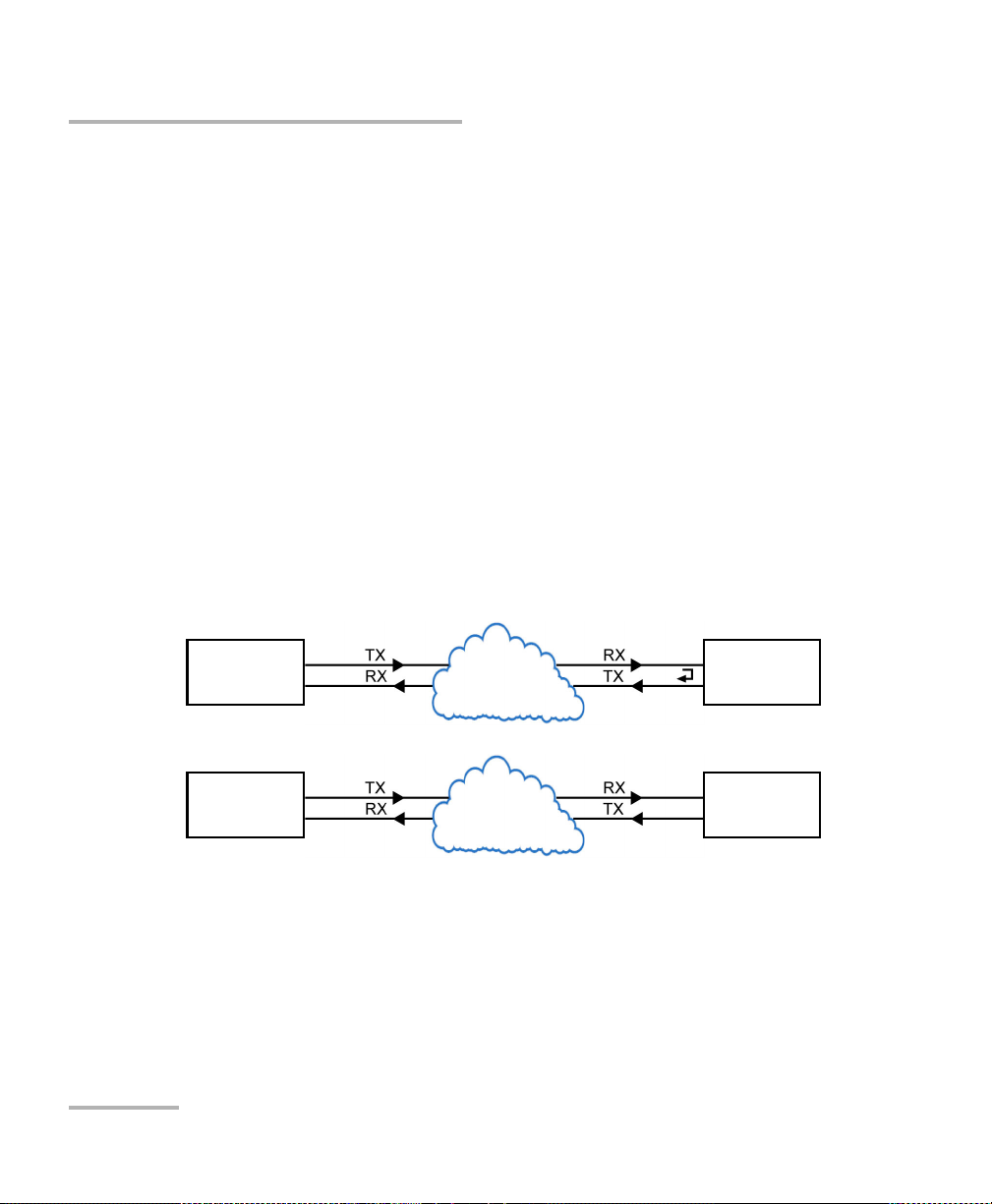
Test Setup - Test Applications
Network
under test
Testing Unit DUT Loopback
FTB-700G/800 Series
Network
under test
Te s t i n g Uni t Te s t i n g Uni t
FTB-700G/800 Series FTB-700G/800 Series
OTN BERT
OTN BERT
Allows OTN (framed and unframed)traffic generation with specific test
pattern for Bit Error Rate analysis.
Typical OTN BERT test applications:
40 FTB-700G/800 Series
Page 51

Test Setup - Test Applications
Path/ Ma pping
The OTN BERT test application offers the following path/mapping
structures depending on the inserted SFP/SFP+ transceiver, and
enabled options.
OTN BERT
NetBlazer 41
Page 52

Test Setup - Test Applications
Network
under test
Testing Unit DUT Loopback
FTB-700G/800 Series
Network
under test
Te s t i n g Uni t Te s t i n g Uni t
FTB-700G/800 Series FTB-700G/800 Series
Testing Unit
FTB-700G/800 Series
Network
under test
Network
under test
SONET/SDH BERT
SONET/SDH BERT
Allows the validation of the SONET or SDH transport protocol by
performing a BERT test to check the traffic or payload stability over a
network facility.
Typical SONET/SDH BERT test applications:
42 FTB-700G/800 Series
Page 53

Test Setup - Test Applications
Path/ Ma pping
The SONET/SDH BERT test application offers the following
path/mapping structures depending on the inserted SFP/SFP+
transceiver, and enabled options.
For SONE T B E RT
SONET/SDH BERT
NetBlazer 43
Page 54

Test Setup - Test Applications
SONET/SDH BERT
For SDH BE RT
44 FTB-700G/800 Series
Page 55

Test Setup - Test Applications
Network
under test
Testing Unit DUT Loopback
FTB-700G/800 Series
Network
under test
Te s t i n g Uni t Te s t i n g Uni t
FTB-700G/800 Series FTB-700G/800 Series
DSn/PDH BERT
DSn/PDH BERT
Allows validation of the DSn or PDH transport protocol by performing a
BERT test to check the traffic or payload stability over a network facility.
Typical DSn/PDH BERT test applications:
NetBlazer 45
Page 56

Test Setup - Test Applications
DSn/PDH BERT
Path/ Ma pping
The DSn/PDH BERT test application offers the following path/mapping
structures depending on model and enabled options.
For DSn:
For PDH:
46 FTB-700G/800 Series
Page 57

Test Setup - Test Applications
Network
under test
Testing Unit DUT Loopback
FTB-700G/800 Series
Network
under test
Te s t i n g Uni t Te s t i n g Uni t
FTB-700G/800 Series FTB-700G/800 Series
SONET/SDH - DSn/PDH BERT
SONET/SDH - DSn/PDH BERT
Allows validation of the DSn or PDH embedded in SONET or SDH transport
protocol by performing a BERT test to check the traffic or payload stability
over a network facility.
Typical SONET/SDH - DSn/PDH BERT test applications:
NetBlazer 47
Page 58

Test Setup - Test Applications
SONET/SDH - DSn/PDH BERT
Path/ Ma pping
The SONET/SDH - DSn/PDH BERT test application offers the following
path/mapping structures depending on the model and enabled
options.
For SONE T:
48 FTB-700G/800 Series
Page 59

For SDH:
Test Setup - Test Applications
SONET/SDH - DSn/PDH BERT
NetBlazer 49
Page 60

Test Setup - Test Applications
Network
under test
Testing Unit DUT Loopback
FTB-700G/800 Series
Network
under test
Te s t i n g Uni t Te s t i n g Uni t
FTB-700G/800 Series FTB-700G/800 Series
NI/CSU Emulation
NI/CSU Emulation
Allows DS1 testing in NI/CSU (Network Interface/Customer Service Unit)
emulation mode.
Typical OTN BERT test applications:
50 FTB-700G/800 Series
Page 61

Test Setup - Test Applications
Network
under test
Testing Unit DUT Loopback
FTB-700G/800 Series
Network
under test
Te s t i n g Uni t Te s t i n g Uni t
FTB-700G/800 Series FTB-700G/800 Series
ISDN PRI
Allows to test and troubleshoot North American or European ISDN PRI
configurations by calling one or all 23 DS1 or 30 E1 PRI channels. Once
connected, the user can perform a channel-by-channel BERT, or talk and
listen via a headset.
Typical ISDN PRI test applications:
ISDN PRI
NetBlazer 51
Page 62
Test Setup - Test Applications
Network
under test
Testing Unit Loopback Unit
FTB-700G/800 Series FTB-700G/800 Series
Network
under test
Testing Unit Remote Unit
FTB-700G/800 Series FTB-700G/800 Series
EtherSAM (Y.1564)
EtherSAM (Y.1564)
EtherSAM can simulate all types of services that will run on the network
and simultaneously qualify all key SLA parameters for each of these
services. Moreover, it validates the QoS mechanisms provisioned in the
network to prioritize the different service types, resulting in more accurate
validation and much faster deployment and troubleshooting.
The EtherSAM (Y.1564) test has to be executed in conjunction with a
remote module. The remote module can be either in loopback
configuration for unidirectional testing or in EtherSAM Dual Test Set mode
for bidirectional testing.
The Dual Test Set test allows bi-directional test between two compatible
modules providing independent results for each test direction. The results
from local-to-remote and remote-to-local are available on the local testing
unit.
Typical EtherSAM (Y.1564) test applications:
Supported Interfaces/Rates: 10M to 10G LAN/WAN.
52 FTB-700G/800 Series
Page 63

Test Setup - Test Applications
Network
under test
Testing Unit Loopback Unit
FTB-700G/800 Series FTB-700G/800 Series
Network
under test
Testing Unit Remote Unit
FTB-700G/800 Series FTB-700G/800 Series
RFC 2544
RFC 2544 allows Ethernet Throughput, Back-to-Back, Frame Loss, and
Latency performance testing in accordance with RFC 2544 specifications.
The RFC 2544 test has to be executed in conjunction with a remote
module. The remote module can be either in loopback configuration for
unidirectional testing or in RFC 2544 Dual Test Set mode for bidirectional
testing.
The Dual Test Set test allows bi-directional test between two compatible
modules providing independent results for each test direction. The results
from local-to-remote and remote-to-local are available on the local testing
unit.
Typical RFC 2544 testapplications:
RFC 2544
Supported Interfaces/Rates: 10M to 10G LAN/WAN.
NetBlazer 53
Page 64

Test Setup - Test Applications
Network
under test
Testing Unit Loopback Unit
FTB-700G/800 Series FTB-700G/800 Series
Network
under test
Testing Unit Testing Unit
FTB-700G/800 Series FTB-700G/800 Series
EtherBERT
EtherBERT
Allows Ethernet unframed and Layer 1 up to Layer 4 traffic generation with
specific test pattern for Bit Error Rate analysis.
Typical EtherBERT test applications:
Supported Interfaces/Rates: 10M to 10G LAN/WAN.
54 FTB-700G/800 Series
Page 65

Test Setup - Test Applications
Network
under test
Testing Unit Loopback Unit
FTB-700G/800 Series FTB-700G/800 Series
Network
under test
Testing Unit Testing Unit
FTB-700G/800 Series FTB-700G/800 Series
Traffic Gen & Mon
Allows Ethernet traffic generation and analysis of up to 16 streams.
Typical Traffic Gen & Mon test applications:
Supported Interfaces/Rates: 10M to 10G LAN/WAN.
Traffic Gen & Mon
NetBlazer 55
Page 66

Test Setup - Test Applications
Network
under test
Testing Unit Smart Loopback Unit
FTB-700G/800 Series FTB-700G/800 Series
Smart Loopback
Smart Loopback
Allows transmitting back the received Ethernet stream of data while
interchanging the source and destination MAC addresses, IP addresses,
and/or UDP/TCP ports. However in Transparent (Pseudo-Physical) mode
the Smart Loopback operates as a physical loopback by transmitting all
received frames unaltered and without discrimination.
The Smart Loopback test can be created locally (refer to Ethernet Test
Applications on page 69) or remotely using an EXFO unit (refer to Discover
Remote Button on page 464) or a Third-Party device (see Third-Party
Remote Loopback on page 57).
Typical Smart Loopback test application:
Supported Interfaces/Rates: 10M to 10G LAN/WAN.
56 FTB-700G/800 Series
Page 67

Test Setup - Test Applications
Smart Loopback
Third-Party Remote Loopback
The Third-party Remote Loopback feature provides the capability to be
discovered and react to loop-up and loop-down commands from a third
party device. This feature is used for unidirectional testing, where the test
stream is transmitted from the third party device to a remote EXFO device.
The looped back test stream is received and analyzed by the third-party
device.
The third-party loopback supports three level of messages:
Layer 2: Only MAC addresses are swapped.
Layer 3: MAC and IP addresses are swapped.
Layer 4: MAC and IP addresses are swapped along with the UDP port.
To emulate a third-party remote device, the loopback mode is set in the
function of the layer of loop messages received. The loop messages are:
Layer 2: Ethernet
Layer 3: IP
Layer 4: UDP/TCP
On receipt of the third-party loop-up command as per requested layer, the
loopback mode is set and initiated on the module.
NetBlazer 57
Page 68

Test Setup - Test Applications
Tes t i n g Uni t
in Through Mode
Network Ethernet Network Ethernet
FTB-700G/800 Series
Through Mode
Through Mode
The Through Mode test application allows traffic to pass through the
FTB-700G/800 Series unit using either two electrical or optical ports for
in-service troubleshooting of live traffic between the carrier/service
provider network and the customer’s network.
Typical Through Mode test application:
Supported Interfaces/Rates: 10M to 1G.
58 FTB-700G/800 Series
Page 69
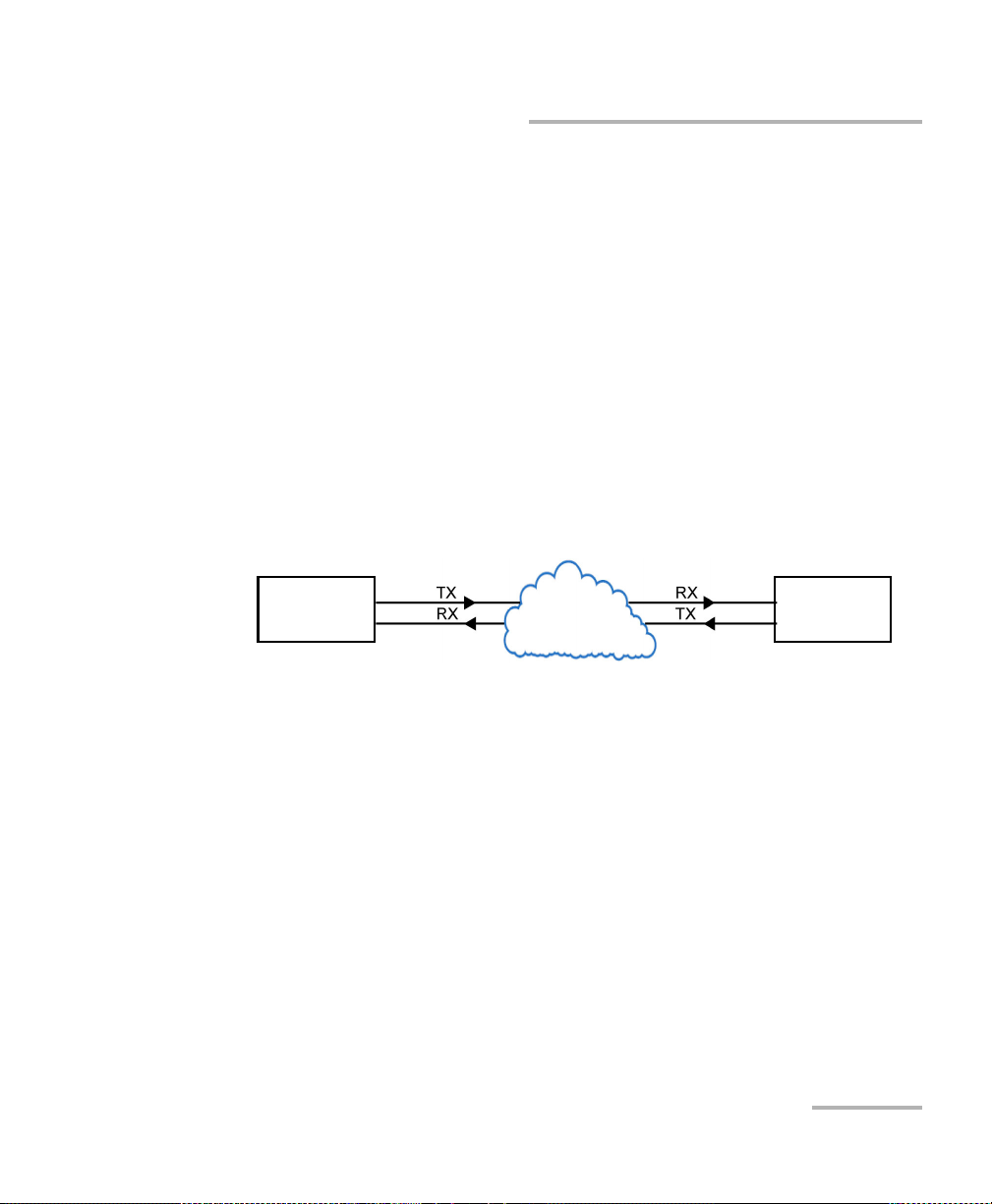
Test Setup - Test Applications
Network
under test
Local Testing Unit Remote Unit
FTB-700G/800 Series FTB-700G/800 Series
TCP Throughput
TCP Throughput
The objective of this test is to find the TCP throughput based on the
successfully transported bytes over the test time. Two units running a TCP
Throughput test are required. One unit will act as the source (Local) and
the other one as the destination (Remote).
The local unit starts sending TCP segments using the Initial Window Size
defined. The window size is adjusted following the TCP algorithm. The
window size is incremented until the Maximum Window Size or
congestion is reached. However, the window size will be reduced when
congestion occurs, then incremented again as described above when the
congestion is cleared. TCP Throughput and windows size statistics will be
gathered throughout the test.
Typical TCP Throughput test application:
Supported Interfaces/Rates: 10M to 1G.
NetBlazer 59
Page 70

Test Setup - Test Applications
MIP
FTB-700G/800 Series Peer MEP
Local MEP
MIP
FTB-700G/800 Series
Local MEP
FTB-700G/800 Series
Smart Loopback with
S-OAM Responder enabled.
Carrier Ethernet OAM
Carrier Ethernet OAM
The Ethernet Service OAM tests are divided in two main categories:
Performance Monitoring measures parameters such as frame delay,
frame loss, and synthetic loss (Y.1731/MEF).
Connectivity Fault Management provides the capability for detecting,
verifying, and isolating connectivity failure (Y.1731/802.1ag/MEF).
Typical Carrier Ethernet OAM test applications:
Supported Interfaces/Rates: 10M to 10G LAN/WAN.
60 FTB-700G/800 Series
Page 71

Test Setup - Test Applications
Testing Unit
Far end equipment
FTB-700G/800 Series
UTP cable
Testing Unit
Unplugged cable
FTB-700G/800 Series
UTP cable
Cable Test
Cable Test
The cable test application is used to diagnose un-shielded twisted pairs
(UTP) cables (up to Category 6e/Class E).
Cable test can be performed everywhere in the network where an
electrical 10/100/1000 Mbit/s Ethernet interface is available for testing. Only
the pairs used by the Ethernet signal will be tested. For 10 Base-T, and
100 Base-TX, pair 2 and 3 will be tested; for 1000 Base-T, all pairs will be
tested. However, if the Ethernet signal is unknown, all four pairs will be
tested.
Even if a link up is not required when testing with a far end equipment, it is
preferable to have the far end equipment powered up to maximize the
cable test results.
Supported Ethernet cable categories are: Category 3/Class C, Category 4,
Category 5, Category 5e/Class D, and Category 6e/Class E.
Note: Cable test result is reliable for cable length of 10 meters to 120 meters
(32.81 feet to 393.7 feet).
Typical C a b le Test app l i c ations:
Supported Interfaces/Rates: 10M to 1000M Electrical.
NetBlazer 61
Page 72

Test Setup - Test Applications
Network
under test
Te s t i n g Uni t G M C l o c k
FTB-700G/800 Series Grand Master Clock Source
1588 PTP
1588 PTP
The 1588 PTP (Precision Time Protocol) test application handles the
1588 PTP communication with the Grand Master (GM) clock, collects
statistics related to packets, and monitors the clock Quality Level.
Typical 1588 PTP test application:
Supported Interfaces/Rates: 10M to 10G LAN.
62 FTB-700G/800 Series
Page 73

Test Setup - Test Applications
Network
under test
Testing Unit Network Equipment
FTB-700G/800 Series EEC
FTB-700G/800 Series
Network
under test
Testing Unit
FTB-700G/800 Series
Testing Unit
SyncE
The Synchronous Ethernet (SyncE) test application provides elementary
test primitives to interactively validate the clock management functions of
a SyncE capable network equipment.
Typical SyncE test applications:
Supported Interfaces/Rates: 100M to 10G LAN.
SyncE
NetBlazer 63
Page 74

Test Setup - Test Applications
Network
under test
Testing Unit Loopback Unit
FTB-700G/800 Series FTB-700G/800 Series
Network
under test
Testing Unit Testing Unit
FTB-700G/800 Series FTB-700G/800 Series
FC BERT
FC BERT
The FC BERT (Fibre Channel BERT) application provides full wire-speed
traffic generation at the FC-2 layer allowing BER testing for link integrity
measurements, latency, buffer-to-buffer credit measurements for
optimization as well as login capabilities.
Typical Fibre Channel test applications:
Supported Interfaces/Rates: 1X, 2X, 4X, 8X, 10X.
64 FTB-700G/800 Series
Page 75

Test Setup - Test Applications
Network
under test
Testing Unit Testing Unit
FTB-700G/800 Series FTB-700G/800 Series
Network
under test
Testing Unit Physical Loopback
FTB-700G/800 Series
CPRI/OBSAI BERT
CPRI/OBSAI BERT
The CPRI/OBSAI BERT unframed test application tests the dark fiber
between the Base Station and the Remote Radio Head.
The Common Public Radio Interface (CPRI) is an industry cooperation
aimed at defining a publicly available specification for the key internal
interface of radio base stations between the Radio Equipment Control
(REC) and the Radio Equipment (RE).
The Open Base Station Architecture Initiative (OBSAI) is a standard that
defines the internal modular structure and interface for base stations.
Typical CPRI/OBSAI BERT test applications:
Supported Interfaces/Rates: 2.4576 Gbit/s, 3.072 Gbit/s.
NetBlazer 65
Page 76

Page 77

7 Selecting and Starting a Test
Modify Structure
Protocol Block
Te s t B l o ck
Clock Block
Interface Block
Physical
Interface Port
A test can be created either by selecting the test from the Test Applications
tab or by loading a previously saved configuration (refer to Save/Load
Button on page 486 for more information).
Transport Test Applications
To select, configure, and start a Transport test:
1. From the test menu, tap Setup.
2. From the Test Applications tab, under Transport, tap a test icon.
3. From the Test Configurator tab configure the signal structure and its
parameters.
3a. Ta p t h e Modify Structure button to set the basic structure of the
test such as the interface/rate, connector, etc. (refer to Modify
Structure Button on page 84).
3b. Tap the interface block to configure the signal parameters (refer
to page 77).
3c. For an embedded signal, tap the protocol block to configure the
signal (refer to page 77).
NetBlazer 67
Page 78

Selecting and Starting a Test
Transport Test Applications
3d. Tap the test block to configure the specific test settings (refer to
page 77). Not available with NI/CSU Emulation test application.
3e. Tap the clock block to configure the clock synchronization (refer
to Clock on page 110).
4. Ta p the Timer tab to automatically start and/or stop the test at a given
time or for a specific duration (refer to Timer on page 234).
5. For additional test configurations refer to Test Functions on page 385.
6. Ta p the Start button from the right navigation bar to start the test. (refer
to Start/Stop Button on page 492). The Summary result page will be
automatically displayed when the test is started from any Setup
configuration page. For additional results, refer to Test Results on
page 241.
7. Ta p the Stop button to stop the test. By default the generate report
pop-up is displayed. If required, tap Yes to generate a report of the test
results and statistics (refer to Report Button on page 481).
68 FTB-700G/800 Series
Page 79
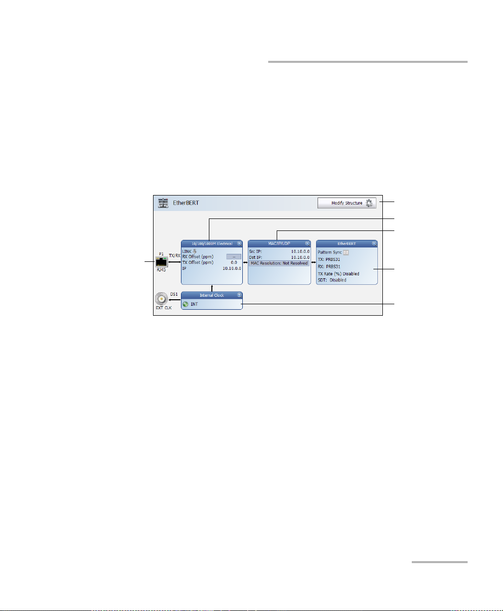
Selecting and Starting a Test
Modify Structure
Protocol Block
Te s t B l o ck
Clock Block
Interface Block
Physical
Interface Port
Ethernet Test Applications
Ethernet Test Applications
To select, configure, and start an Ethernet test:
1. From the test menu, tap Setup.
2. From the Test Applications tab, under Ethernet, tap a test icon.
3. From the Test Configurator tab configure the interface structure and
its parameters.
3a. Tap the Modify Structure button to set the basic structure of the
test such as the interface/rate, connector, etc. (refer to Modify
Structure Button on page 84).
3b. Tap the interface block to configure the interface parameters
(refer to page 77). Ensure that the link is up and the power level
(when supported) is present in the status bar before proceeding
to the next step (refer to Status Bar on page 26).
NetBlazer 69
Page 80

Selecting and Starting a Test
Ethernet Test Applications
3c. Tap the protocol block1 to configure the frame structure and its
parameters (refer to page 78).
3d. Tap the test block
page 78).
3e. Tap the clock block to configure the clock synchronization (refer
to Clock on page 110).
4. Ta p the Timer tab to automatically start and/or stop the test at a given
time or for a specific duration (refer to Timer on page 234).
5. For additional test configurations refer to Test Functions on page 385.
6. Ta p the Start button from the right navigation bar to start the test (refer
to Start/Stop Button on page 492). The Summary result page will be
automatically displayed when the test is started from any Setup
configuration page. For additional results refer to Test Results on
page 241.
7. Depending on the test, when the test ends automatically or manually
stopped, the generate report pop-up is displayed by default. If required,
tap Yes to generate a report of the test results and statistics (refer to
Report Button on page 481 for more information).
2
to configure the specific test settings (refer to
1. Not available with Smart Loopback, Through Mode, TCP Throughput, and Cables Test.
2. Not available with Traffic Gen & Mon and Through Mode.
70 FTB-700G/800 Series
Page 81
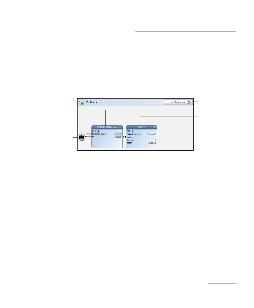
Selecting and Starting a Test
Modify Structure
Te s t B l o ck
Interface Block
Physical
Interface Port
Packe t S ync Test A p plicatio n s
Packet Sync Test Applications
To select, configure, and start a Packet Sync test:
1. From the test menu, tap Setup.
2. From the Test Applications tab, under Packet Sync, tap a test icon.
3. From the Test Configurator tab configure the interface structure and
its parameters.
3a. Tap the Modify Structure button to set the basic structure of the
test such as the interface/rate, connector, etc. (refer to Modify
Structure Button on page 84).
3b. Tap the interface block to configure the interface parameters
(refer to page 77). Ensure that the link is up and the power level
(when supported) is present in the status bar before proceeding
to the next step (refer to Status Bar on page 26).
3c. Tap the test block to configure the specific test settings (refer to
page 79).
NetBlazer 71
Page 82

Selecting and Starting a Test
Packet Sync Test Applications
4. Ta p the Timer tab to automatically start and/or stop the test at a given
time or for a specific duration (refer to Timer on page 234).
5. For additional test configurations refer to Test Functions on page 385.
6. Ta p the Start button from the right navigation bar to start the test (refer
to Start/Stop Button on page 492). The Summary result page will be
automatically displayed when the test is started from any Setup
configuration page. For additional results refer to Test Results on
page 241.
7. Depending on the test, when the test ends automatically or manually
stopped, the generate report pop-up is displayed by default. If required,
tap Yes to generate a report of the test results and statistics (refer to
Report Button on page 481 for more information).
72 FTB-700G/800 Series
Page 83

Selecting and Starting a Test
Fibre Channel Test Application
Fibre Channel Test Application
To select, configure, and start a Fibre Channel test:
1. From the test menu, tap Setup.
2. From the Test Applications tab, under Fibre Channel, tap the
FC BERT test icon.
3. Ta p the Interface tab to configure the physical interface, World Wide
Name, Buffer to Buffer Flow Control, and Login settings. Refer to
Interface - Port (Fibre Channel) on page 139 for more information.
Ensure that the link is up and the power level is present in the status
bar before proceeding to the next step (refer to Status Bar on page 26).
4. Ta p the Global tab to configure Frame, Pass/Fail Verdict, BER,
Round-Trip Latency, and Test Ti m e r. Refer to Global (Fibre Channel)
on page 130 for more information.
5. Ta p the Start button from the right navigation bar to start the test (refer
to Start/Stop Button on page 492). The Summary result page will be
automatically displayed when the test is started from any Setup
configuration page. For additional results refer to Test Results on
page 241.
6. When the test ends automatically or manually stopped, the generate
report pop-up is displayed by default. If required, tap Yes to generate a
report of the test results and statistics (refer to Report Button on
page 481 for more information).
NetBlazer 73
Page 84

Selecting and Starting a Test
Modify Structure
Te s t B l o ck
Interface Block
Physical
Interface Port
Wireless Test Application
Wireless Test Application
To select, configure, and start a Wireless test:
1. From the test menu, tap Setup.
2. From the Test Applications tab, under Wireless, tap the CPRI/OBSAI
BERT test icon.
3. From the Test Configurator tab configure the interface structure and
its parameters.
3a. Tap the Modify Structure button to set the basic structure of the
test such as the interface/rate, connector, etc. (refer to Modify
Structure Button on page 84).
3b. Tap the interface block to configure the interface parameters
(refer to page 133). Ensure that the power level is present in the
status bar before proceeding to the next step (refer to Status Bar
on page 26).
3c. Tap the test block to configure the specific test settings (refer to
page 114).
74 FTB-700G/800 Series
Page 85

Selecting and Starting a Test
Wireless Test Application
4. Ta p the Timer tab to automatically start and/or stop the test at a given
time or for a specific duration (refer to Timer on page 234).
5. For additional test configurations refer to Test Functions on page 385.
6. Ta p the Start button from the right navigation bar to start the test (refer
to Start/Stop Button on page 492). The Summary result page will be
automatically displayed when the test is started from any Setup
configuration page. For additional results refer to Test Results on
page 241.
7. When the test ends automatically or manually stopped, the generate
report pop-up is displayed by default. If required, tap Yes to generate a
report of the test results and statistics (refer to Report Button on
page 481 for more information).
NetBlazer 75
Page 86

Page 87

8 Test Setup - Test Configurator,
Timer, and System
The Test Setup menu offers the following structure:
Test Configurator for Transport Test Applications.
Block Subtab or Pop Up
ButtonModify Structure XXXXXX 84
Signal Auto-Detect - - X - X X 95
Interface SFP/SFP+ X X - X - - 109
FTFL/PT X----- 126
Labels -X-X-- 150
Signal XXXXXX 198
Traces 236 239 - 239 - - <---
Protocol Signal - - - X - - 204
TestBERT XXXX - - 101
ISDN PRI - Call Management -----X143
ISDN PRI - ISDN Settings -----X148
ClockClock XXXXXX 110
a. OTN BERT
b. SONET/SDH BERT
c. DSn/PDH BERT
d. SONET/SDH - DSn/PDH BERT
e. NI/CSU Emulation
f. ISDN PRI
a
b
c
d
e
Page
f
Test Application
NetBlazer 77
Page 88

Test S e t u p - Test Config urator, Timer, and System
Test Configurator for Ethernet Test Applications.
Block Subtab or Pop Up
a
ButtonModify Structure XXXXXXXXX 84
InterfaceSFP/SFP+ XXXXXXXX - 109
Interface XXXXXXXXX 133
Network XXXXXXXXX 164
ProtocolMAC/IP/UDP XXXX ----- 151
Services - Global X-------- 188
Services - Profile X-------- 191
Streams - Global ---X----- 220
Streams - Profile ---X----- 222
Test Cable Test --------X 107
EtherBERT and
--X------ 114
Unframed BERT
EtherSAM - Burst X-------- 118
EtherSAM - Global X-------- 120
EtherSAM - Ramp X-------- 124
RFC 2544 - Global -X------- 169
RFC 2544 - Subtests -X------- 172
S-OAM -------X- 181
Smart Loopback ----X---- 218
TCP Throughput ------X-- 232
Clock Clock XXXXX- XX - 110
Test Application
b
c
d
e
f
g
h
Page
i
a. EtherSAM
b. RFC 2544
c. EtherBERT
d. Traffic Gen & Mon
e. Smart Loopback
f. Through Mode
g. TCP Throughput
h. Carrier Ethernet OAM
i. Cable Test
78 FTB-700G/800 Series
Page 89

Test Se t u p - Test Config urator, Timer, and System
Test Configurator for Packet Sync Test Applications.
Block Subtab or Pop Up
Button Modify Structure X X 84
Interface Interface X X 133
Network X X 164
SFP/SFP+ X X 109
Test 1588 PTP X - 96
SyncE - X 229
Fibre Channel Test Application.
Tab or Subtab
Interface - Port X 139
SFP/SFP+ X 109
Global X 130
Test Application
Page
1588 PTP SyncE
Test Application
Page
FC BERT
NetBlazer 79
Page 90

Test S e t u p - Test Config urator, Timer, and System
Wireless Test Application.
Block Subtab or Pop Up
Button Modify Structure X 84
Interface Interface X 133
SFP/SFP+ X 109
Te s t U n f ram e d B E R T X 11 4
Timer, see page 234.
System, see page 231.
Test Application
Page
CPRI/OBSAI BERT
80 FTB-700G/800 Series
Page 91
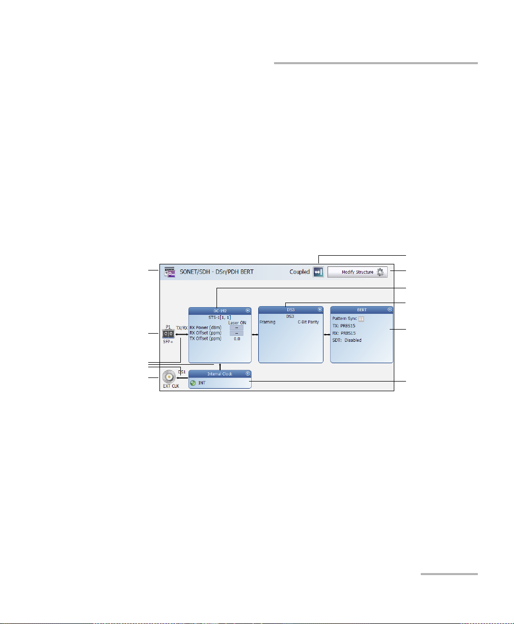
Test Se t u p - Test Config urator, Timer, and System
Physical
Interface Port
Test Application
Modify Structure
Te s t B l o ck
Clock Block
Physical Clock Port
Interface Block
Arrows
Protocol Block
To po l o gy
Test Configurator Overview
Test Configurator Overview
The Test Configurator tab displays the interconnected blocks composing
the test structure. Each block of the test structure gives an overview of its
configuration/status. Availability of each block depends on the selected test
application and its structure. Arrows are used to indicate the
interconnection between blocks as well as the direction of the clock and
data flow. Tap on a block to change the configuration parameters of this
block.
From the Test menu, tap Setup, and the Test Configurator tab.
Transport Test Applications:
NetBlazer 81
Page 92

Test S e t u p - Test Config urator, Timer, and System
Physical
Interface Port
Test Application
Modify Structure
Protocol Block
Te s t B l o ck
Clock Block
Physical Clock Port
Interface Block
Arrows
Physical
Interface Port
Test Application
Modify Structure
Te s t B l o ck
Interface Block
Arrows
Physical
Interface Port
Test Application
Modify Structure
Te s t B l o ck
Interface Block
Arrows
Test Configurator Overview
Ethernet Test Applications:
Packet Sync Test Applications:
82 FTB-700G/800 Series
Wireless Test Application:
Page 93

Test Se t u p - Test Config urator, Timer, and System
Test Configurator Overview
Test Application indicates the selected test application.
Topology, for Transport Test Applications, indicates the selected test
topology.
Modify Structure button, allows the configuration of the physical port
and the signal interface structure.
Physical Interface Port indicates the physical interface port.
Arrows are used to indicate the interconnection between blocks as
well as the direction of the clock and data flow.
A line with an arrow on both ends indicates a bidirectional
communication (TX/RX).
A line with a single arrow indicates a unidirectional communication,
either TX when going out of a block or RX when going into a block.
A line going out of a block returning back to the same block, indicates
a loopback communication.
Physical Clock Port indicates the direction, TX or RX, of the selected
clock. The arrow next to the physical clock image indicates if a clock is
generated (TX, arrow pointing to the left) or received (RX, arrow
pointing to the right) at/from the physical EXT CLK port.
Interface Block displays an overview of the interface settings and
status. Tap on the interface block to change the settings and to see
detailed status.
Protocol Block displays an overview of either the frame structure and
its parameters for Ethernet test applications or the embedded signal for
Transport test applications. This block is not present for all tests. Tap on
the protocol block to change the settings and to see detailed status.
Test Block displays an overview of the test settings and status. Tap on
the test block to change the settings and to see detailed status.
Clock Block displays an overview of the clock settings and status. Tap
on the clock area to change the settings and to see detailed status.
NetBlazer 83
Page 94

Test S e t u p - Test Config urator, Timer, and System
Modify Structure Button
Modify Structure Button
From the Test menu, tap Setup, Test Configurator, and the Modify
Structure button.
For Transport Test Applications
TX/RX allows the configuration of the following parameters for either
TX/RX or TX and RX in Decoupled topology.
Interface/Rate: Select the desired interface rate. Choices depend on
the selected test and the rates available on themodule.
Test Interface/Rate
OTN OTU2 [10.709 Gbit/s]
OTU1e [11.049 Gbit/s]
OTU2e [11.096 Gbit/s]
OTU1f [11.270 Gbit/s]
OTU2f [11.318 Gbit/s]
OTU1 [2.666 Gbit/s]
SONET (Serial) OC-192 [9.953 Gbit/s]
OC-48 [2.488 Gbit/s]
OC-12[622.08Mbit/s]
OC-3 [155.520 Mbit/s]
OC-1 [51.840 Mbit/s]
STS-3e [155.520 Mbit/s]
STS-1e [51.840 Mbit/s]
SDH (Serial) STM-64 [9.953 Gbit/s]
STM-16 [2.488 Gbit/s]
STM-4 [622.080 Mbit/s]
STM-1 [155.520 Mbit/s]
STM-0 [51.840 Mbit/s]
STM-1e [155.520 Mbit/s]
STM-0e [51.840 Mbit/s]
84 FTB-700G/800 Series
Page 95

Test Se t u p - Test Config urator, Timer, and System
Test Interface/Rate
DSn DS1[1.544 Mbit/s]
DS3 [44.736 Mbit/s]
PDH E1 [2.048 Mbit/s]
E3 [34.368 Mbit/s]
E4 [139.264 Mbit/s]
Modify Structure Button
NI/CSU
DS1
Emulation
ISDN PRI DS1 [1.544 Mbit/s]
E1 [2.048 Mbit/s]
Connector allows the selection of the module’s port.
Interface/Rate Connector
OTU2 [10.709 Gbit/s]
Port 1 - SFP+
OTU1e [11.049 Gbit/s]
OTU2e [11.096 Gbit/s]
OTU1f [11.270 Gbit/s]
OTU2f [11.318 Gbit/s]
OC-192 [9.953 Gbit/s]
STM-64 [9.953 Gbit/s]
OTU1 [2.666 Gbit/s]
Port 1 - SFP
OC-48 [2.488 Gbit/s]
OC-12 [622.08 Mbit/s]
OC-3 [155.520 Mbit/s]
OC-1 [51.840 Mbit/s]
STM-16 [2.488 Gbit/s]
STM-4 [622.080 Mbit/s]
STM-1 [155.520 Mbit/s]
STM-0 [51.840 Mbit/s]
NetBlazer 85
Page 96

Test S e t u p - Test Config urator, Timer, and System
Modify Structure Button
Interface/Rate Connector
STS-3e [155.520 Mbit/s]
Port 1 - BNC
STS-1e [51.840 Mbit/s]
STM-1e [155.520 Mbit/s]
STM-0e [51.840 Mbit/s]
DS1[1.544 Mbit/s] Port 1 - Bantam
Port 1 - RJ48C
E1 [2.048 Mbit/s] Port 1 - Bantam
Port 1 - BNC
Port 1 - RJ48C
DS3 [44.736 Mbit/s]
Port 1 - BNC
E3 [34.368 Mbit/s]
E4 [139.264 Mbit/s]
Framing: For OTN BERT, and SONET/SDH BERT test applications, the
framing is set to Framed.
OTN Multiplexing, only available with OTN BERT, indicates the OTN
test mapping.
Interface/Rate OTN Multiplexing
OTU1 [2.666 Gbit/s] ODU1
OTU2 [10.709 Gbit/s] ODU2
OTU1e [11.049 Gbit/s] ODU1e
OTU2e [11.096 Gbit/s] ODU2e
OTU1f [11.270 Gbit/s] ODU1f
OTU2f [11.318 Gbit/s] ODU2f
86 FTB-700G/800 Series
Page 97

Test Se t u p - Test Config urator, Timer, and System
Modify Structure Button
SONET/SDH Multiplexing allows the selection of SONET/SDH
multiplexing. Only available with SONET/SDH BERT test application.
Embedded
SONET/SDH
SONET/SDH Multiplexing
OC-192 STS-192c, STS-48c, STS-12c, STS-3c, STS-1,
STS-1/VT2, STS-1/VT1.5
STM-64 AU-4-64c, AU-4-16c, AU-4-4c, AU-4, AU-4/TU-3,
AU-4/TU-12, AU-4/TU-11, AU-3, AU-3/TU-12,
AU-3/TU-11
OC-48 STS-48c, STS-12c, STS-3c, STS-1, STS-1/VT2,
STS-1/VT1.5
STM-16 AU-4-16c, AU-4-4c, AU-4, AU-4/TU-3, AU-4/TU-12,
AU-4/TU-11, AU-3, AU-3/TU-12, AU-3/TU-11
OC-12 STS-12c, STS-3c, STS-1, STS-1/VT2, STS-1/VT1.5
STM-4 AU-4-4c, AU-4, AU-4/TU-3, AU-4/TU-12, AU-4/TU-11,
AU-3, AU-3/TU-12, AU-3/TU-11
OC-3 STS-3c, STS-1, STS-1/VT2, STS-1/VT1.5
STM-1 AU-4, AU-4/TU-3, AU-4/TU-12, AU-4/TU-11, AU-3,
AU-3/TU-12, AU-3/TU-11
OC-1 STS-1, STS-1/VT2, STS-1/VT1.5
S
TS-3e STS-3c, STS-1, STS-1/VT2, STS-1/VT1.5
STS-1e STS-1, STS-1/VT2, STS-1/VT1.5
STM-0 AU-3, AU-3/TU-12, AU-3/TU-11
STM-1e AU-4, AU-4/TU-3, AU-4/TU-12, AU-4/TU-11, AU-3,
AU-3/TU-12, AU-3/TU-11
STM-0e AU-3, AU-3/TU-12, AU-3/TU-11
NetBlazer 87
Page 98

Test S e t u p - Test Config urator, Timer, and System
Modify Structure Button
DSn/PDH Multiplexing, available with SONET/SDH - DSn/PDH BERT
and DSn/PDH test applications, allows the selection of the DSn/PDH
multiplexing.
Interface/Rate DSn/PDH Multiplexing
DS3 None (default), DS1, E1
DS1 None
E4 None (default), E3, E3/E2/E1
E3 None (default), E2/E1
E1 None
Client is set to Pattern.
Switch Type
1
allows the selection of the Switch Type for ISDN DS1 and
E1 rates. The switch type in brackets indicates the switch type in
abbreviated format.
DS1: National ISDN (NI-4) - (default), National ISDN (NI-3),
National ISDN (NI-2), National ISDN (NI-1), AT&T 4ESS ,
AT&T 5ESS, and Nortel DMS-100/250.
E1: Euro ISDN (default), Euro Q.SIG, and Euro VN6.
Emulation Mode
1
: TE (Terminal Equipment) - (default), and NT
(Network Termination).
1. Only available with ISDN PRI test application.
88 FTB-700G/800 Series
Page 99

Test Se t u p - Test Config urator, Timer, and System
Modify Structure Button
Topol og y allows the selection of the network test topology.
Coupled uses the same settings for both the TX and RX signals.
Decoupled uses independent settings for TX and RX signals.
However, the pattern and some other parameters are always
coupled. Decoupled is not supported with OTN BERT test
application.
Through loops the RX signal to the TX port without TX overwrite
capabilities.
Dual RX uses two DS1 or DS3 signals at the same time. Both RX
ports are coupled at the exception of the termination mode. Only
available with DS1 and DS3 signal rates.
NetBlazer 89
Page 100

Test S e t u p - Test Config urator, Timer, and System
Modify Structure Button
For Ethernet Test Applications
Interface/Rate choices depend on the selected test and the rates
available on themodule.
Test Interface/Rate
RFC 2544
EtherBERT
Traffic Gen & Mon
Smart Loopback
EtherSAM
10GE WAN
10GE LAN
1GE Optical
100M Optical
10/100/1000M Electrical
Carrier Ethernet OAM
Through Mode 1GE Optical
100M Optical
TCP Throughput 1GE Optical
100M Optical
10/100/1000M Electrical
Cable Test 10/100/1000M Electrical
Primary Port / Secondary Port, available with Through Mode test
application, allows to select the module’s ports that are respectively
used as primary (Port 1) and secondary (Port 2) port. The configuration
of the network configuration parameters will be available on the
Primary Port only.
90 FTB-700G/800 Series
 Loading...