

Page 1
FTB-700 Series
OTDR for FTB-1
User Guide
Page 2

Copyright © 2006–2013 EXFO Inc. All rights reserved. No part of this
publication may be reproduced, stored in a retrieval system or transmitted
in any form, be it electronically, mechanically, or by any other means such
as photocopying, recording or otherwise, without the prior written
permission of EXFO Inc. (EXFO).
Information provided by EXFO is believed to be accurate and reliable.
However, no responsibility is assumed by EXFO for its use nor for any
infringements of patents or other rights of third parties that may result from
its use. No license is granted by implication or otherwise under any patent
rights of EXFO.
EXFO’s Commerce And Government Entities (CAGE) code under the North
Atlantic Treaty Organization (NATO) is 0L8C3.
The information contained in this publication is subject to change without
notice.
Trademarks
EXFO’s trademarks have been identified as such. However, the presence
or absence of such identification does not affect the legal status of any
trademark.
Units of Measurement
Units of measurement in this publication conform to SI standards and
practices.
Patents
Feature(s) of this product is/are protected by one or more of US patent
6,612,750; and Canadian patent 2,800,361 and equivalent patents pending
and/or granted in other countries.
Version number: 20.0.0
ii FTB-700 Series
Page 3

Contents
Contents
Certification Information ..................................................................................................... viii
1 Introducing the FTB-700 OTDR .................................................................... 1
Main Features .........................................................................................................................2
Trace Acquisition Modes .........................................................................................................2
Optional Software Packages ...................................................................................................3
Data Post-Processing ..............................................................................................................3
Bidirectional Analysis Application ...........................................................................................4
OTDR Basic Principles ..............................................................................................................5
Conventions ............................................................................................................................7
2 Safety Information ....................................................................................... 9
General Safety Information .....................................................................................................9
Other Safety Symbols on Your Unit .......................................................................................10
Laser Safety Information .......................................................................................................11
3 Getting Started with Your OTDR ............................................................... 13
Inserting and Removing Test Modules ..................................................................................13
Starting Module Applications ...............................................................................................18
Timer ....................................................................................................................................20
4 Preparing Your OTDR for a Test ................................................................. 21
Installing the EXFO Universal Interface (EUI) .........................................................................21
Cleaning and Connecting Optical Fibers ...............................................................................22
Naming Trace Files Automatically .........................................................................................24
Enabling or Disabling the First Connector Check ..................................................................28
Setting Macrobend Parameters .............................................................................................29
5 Testing Fibers in Auto Mode ...................................................................... 31
6 Testing Fibers in Advanced Mode ............................................................. 35
Setting the Autorange Acquisition Time ...............................................................................40
Setting the IOR, RBS Coefficient, and Helix Factor ................................................................41
Setting Distance Range, Pulse Width, and Acquisition Time .................................................43
Enabling the High-Resolution Feature ...................................................................................46
Enabling or Disabling Analysis After Acquisition ...................................................................48
Setting Pass/Fail Thresholds ..................................................................................................50
Setting a Default Span Start and Span End ...........................................................................55
OTDR iii
Page 4

Contents
7 Testing Fibers in Template Mode (optional) ..............................................57
Template Principle .................................................................................................................57
Restrictions of Template Mode ..............................................................................................58
Acquiring the Reference Trace ..............................................................................................60
Acquiring Traces in Template Mode ......................................................................................62
Selecting a Reference Trace ...................................................................................................69
8 Testing Fibers in Fault Finder Mode ...........................................................71
Acquiring Traces in Fault Finder Mode ..................................................................................71
Naming Fault Finder Files Automatically ...............................................................................74
Selecting the Default File Format for the Fault Finder Traces .................................................76
Enabling or Disabling the Confirmation of Fault Finder File Name ........................................78
Enabling or Disabling the Storage Feature ............................................................................80
Enabling or Disabling the First Connector Check for Fault Finder .........................................81
Enabling or Disabling the Touchscreen Keyboard ..................................................................83
Setting Trace Display Parameters ..........................................................................................84
Selecting the Distance Units .................................................................................................86
9 Customizing Your OTDR ..............................................................................89
Selecting the Default File Format ..........................................................................................89
Enabling or Disabling File Name Confirmation .....................................................................91
Selecting the Distance Units .................................................................................................93
Customizing the Acquisition Distance Range Values .............................................................95
Customizing the Acquisition Time Values .............................................................................97
Enabling or Disabling the Touchscreen Keyboard ..................................................................99
Displaying or Hiding the Optional Features ........................................................................100
iv FTB-700 Series
Page 5

Contents
10 Analyzing Traces and Events ................................................................... 101
Graph View .........................................................................................................................102
Linear View .........................................................................................................................104
Summary Table ...................................................................................................................106
Events Tab ...........................................................................................................................108
Measure Tab .......................................................................................................................112
Trace Info. Tab ....................................................................................................................112
Displaying the Graph in Full Screen ....................................................................................113
Selecting the Default View ..................................................................................................115
Automatically Displaying the Event Table after Acquisitions ...............................................117
Automatically Zooming in on the Fiber Span ......................................................................118
Using Zoom Controls ..........................................................................................................119
Setting Trace Display Parameters ........................................................................................122
Customizing the Event Table ...............................................................................................124
Displaying or Hiding a Trace ...............................................................................................126
Clearing Traces from the Display .........................................................................................128
Viewing and Modifying Current Trace Settings ...................................................................129
Modifying Events ................................................................................................................134
Inserting Events ..................................................................................................................138
Deleting Events ...................................................................................................................140
Managing Comments .........................................................................................................142
Changing the Attenuation of Fiber Sections .......................................................................144
Setting the Analysis Detection Thresholds ..........................................................................146
Analyzing or Reanalyzing a Trace ........................................................................................149
Analyzing the Fiber on a Specific Fiber Span .......................................................................151
Enabling or Disabling the Detection of Reflective Ends of Fiber ..........................................152
Swapping Traces .................................................................................................................155
Opening Trace Files .............................................................................................................156
11 Analyzing the Results Manually .............................................................. 161
Selecting the Attenuation and Loss Values that Will Be Displayed ......................................161
Using Markers .....................................................................................................................163
Getting Event Distances and Relative Powers ......................................................................164
Getting Event Loss (Four-Point and Least-Square Approximation) ......................................165
Getting Attenuation (Two-Point and Least-Square Approximation) ....................................170
Getting Reflectance ............................................................................................................172
Getting Optical Return Loss (ORL) .......................................................................................173
12 Managing Trace Files from the OTDR Test Application .......................... 175
Saving a Trace in a Different Format ...................................................................................175
OTDR Trace File Compatibility .............................................................................................176
Copying, Moving, Renaming, or Deleting Trace Files ..........................................................178
OTDR v
Page 6

Contents
13 Creating and Generating Reports ............................................................179
Adding Information to the Test Results ...............................................................................179
Generating a Report ...........................................................................................................181
14 Using the OTDR as a Light Source ............................................................187
15 Analyzing Traces with the Bidirectional Analysis Application
(Optional) ..................................................................................................191
Starting and Exiting the Bidirectional Analysis Application .................................................193
Creating Bidirectional Measurement Files ...........................................................................195
Opening Existing Bidirectional Measurement Files ..............................................................199
Displaying Traces and Bidirectional Measurement ..............................................................200
Viewing Results ..................................................................................................................202
Reanalyzing Traces and Regenerating the Bidirectional Measurement ................................213
Modifying the Alignment of Unidirectional Traces ..............................................................215
Using Zoom Controls ..........................................................................................................219
Using Markers to Edit Events ..............................................................................................223
Inserting Events ..................................................................................................................225
Modifying Events ................................................................................................................229
Deleting Events ...................................................................................................................233
Changing the Attenuation of Fiber Sections .......................................................................235
Setting General Parameters ................................................................................................238
Customizing the Events Table .............................................................................................241
Saving the Span-Start and Span-End Information ...............................................................244
Setting Pass/Fail Thresholds ................................................................................................245
Modifying Trace Analysis Settings .......................................................................................250
Saving Traces ......................................................................................................................255
Exporting Unidirectional Traces from Bidirectional Files ......................................................257
Adding Information to the Test Results ...............................................................................259
Creating Reports .................................................................................................................261
16 Maintenance ..............................................................................................265
Cleaning EUI Connectors ....................................................................................................265
Verifying Your OTDR ...........................................................................................................268
Recalibrating the Unit .........................................................................................................276
Recycling and Disposal (Applies to European Union Only) ..................................................277
17 Troubleshooting ........................................................................................279
Contacting the Technical Support Group ............................................................................282
Transportation ....................................................................................................................283
vi FTB-700 Series
Page 7

Contents
18 Warranty ................................................................................................... 285
General Information ...........................................................................................................285
Liability ...............................................................................................................................286
Exclusions ...........................................................................................................................286
Certification ........................................................................................................................286
Service and Repairs .............................................................................................................287
EXFO Service Centers Worldwide ........................................................................................288
A Technical Specifications ........................................................................... 289
B Description of Event Types ...................................................................... 293
Span Start ..........................................................................................................................294
Span End ...........................................................................................................................294
Short Fibers .......................................................................................................................294
Continuous Fiber ...............................................................................................................295
End of Analysis ..................................................................................................................296
Non-Reflective Event ..........................................................................................................297
Reflective Event .................................................................................................................298
Positive Event .....................................................................................................................299
Launch Level ......................................................................................................................300
Fiber Section ......................................................................................................................301
Merged Event ....................................................................................................................302
Echo ..................................................................................................................................308
Reflective Event (Possible Echo) .........................................................................................309
Index .............................................................................................................. 311
OTDR vii
Page 8

Certification Information
Certification Information
North America Regulatory Statement
This unit was certified by an agency approved in both Canada and the
United States of America. It has been evaluated according to applicable
North American approved standards for product safety for use in Canada
and the United States.
Electronic test and measurement equipment is exempt from FCC part 15,
subpart B compliance in the United States of America and from ICES-003
compliance in Canada. However, EXFO Inc. makes reasonable efforts to
ensure compliance to the applicable standards.
The limits set by these standards are designed to provide reasonable
protection against harmful interference when the equipment is operated in
a commercial environment. This equipment generates, uses, and can
radiate radio frequency energy and, if not installed and used in accordance
with the user guide, may cause harmful interference to radio
communications. Operation of this equipment in a residential area is likely
to cause harmful interference in which case the user will be required to
correct the interference at his own expense.
Modifications not expressly approved by the manufacturer could void the
user's authority to operate the equipment.
European Community Declaration of Conformity
An electronic version of the declaration of conformity for your product is
available on our website at www.exfo.com. Refer to the product’s page on
the Web site for details.
viii FTB-700 Series
Page 9
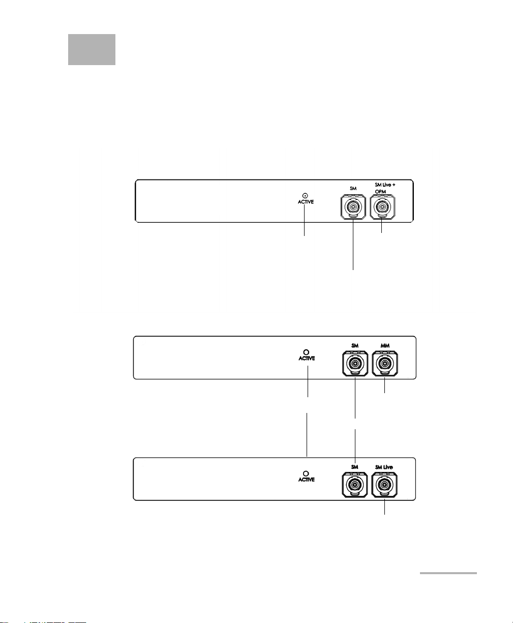
1 Introducing the FTB-700 OTDR
OTDR port (singlemode)
OTDR port (singlemode
live and On-line power
meter)
Active LED
FTB-720 / FTB-720G / FTB-720G+
FTB-730 / FTB-730G / FTB-730G+
OTDR port (singlemode)
OTDR port (multimode)
Active LED
OTDR port
(singlemode live)
The FTB-700 OTDR allows you to characterize a fiber-optic span, usually
optical fiber sections joined by splices and connectors. The optical time
domain reflectometer (OTDR) provides an inside view of the fiber, and can
calculate fiber length, attenuation, breaks, total return loss, and splice,
connector and total losses.
OTDR 1
Page 10

Introducing the FTB-700 OTDR
Main Features
Main Features
The OTDR:
Offers impressive dynamic range with short dead zones
Performs quick acquisitions with low noise levels to enable accurate
low-loss splice location.
Acquires OTDR traces made of up to 256 000 points that provide a
sampling resolution as fine as 4 cm.
Includes a light source.
Trace Acquisition Modes
The OTDR application provides the following trace acquisition modes:
Auto: Automatically calculates fiber length, sets acquisition
parameters, acquires traces, and displays event tables and acquired
traces.
Advanced: Offers all the tools needed to perform integral OTDR tests
and measurements and gives you control over all test parameters.
Template (optional): Tests fibers and compares the results to a
reference trace that was previously acquired and analyzed. This allows
you to save time when testing a large number of fibers. Reference trace
documentation is also automatically copied to new acquisitions.
Fault Finder: Rapidly locates fiber ends and displays the length of the
fiber under test. This allows you to perform quick tests without having
to set all the acquisition parameters.
2 FTB-700 Series
Page 11

Introducing the FTB-700 OTDR
Optional Software Packages
Optional Software Packages
There are two optional software packages offered with the application.
With the optional Auto Diagnostic (AD) software package you can:
Have access to the “linear view”, which displays the events
sequentially, from left to right.
Find macrobends and view the related information.
View the summary table, which gives, for each wavelength, the global
status of the results, the span loss and span ORL values.
Test in Fault Finder mode, to rapidly locate fiber ends.
With the optional Event Characterization (EC) software package you can:
Have access to the OTDR Bidirectional application and perform a
bidirectional analysis on two unidirectional OTDR traces.
Test in Template Mode, test fibers and compare the results to a
reference trace.
Data Post-Processing
You can install the FastReporter application (available on the DVD that
came with your product) on a computer to view and analyze traces
without having to use the FTB-1 and an OTDR. You can also access more
features such as:
customized printout
batch printing
conversion of traces to many formats such as Telcordia or ASCII
OTDR 3
Page 12

Introducing the FTB-700 OTDR
Bidirectional Analysis Application
Bidirectional Analysis Application
Note: This function is available with the optional Event Characterization (EC)
software package only.
You can improve the accuracy of your loss measurements with the
bidirectional analysis application (available with OTSView). This utility
uses OTDR acquisitions from both ends of a fiber span (singlemode traces
only) to average loss results for each event.
4 FTB-700 Series
Page 13

Introducing the FTB-700 OTDR
Distance
c
n
---
t
2
---
=
OTDR Basic Principles
OTDR Basic Principles
An OTDR sends short pulses of light into a fiber. Light scattering occurs in
the fiber due to discontinuities such as connectors, splices, bends, and
faults. An OTDR then detects and analyzes the backscattered signals. The
signal strength is measured for specific intervals of time and is used to
characterize events.
The OTDR calculates distances as follows:
where
c = speed of light in a vacuum (2.998 x 10
t = time delay from the launch of the pulse to the reception of the
pulse
n = index of refraction of the fiber under test (as specified by the
manufacturer)
8
m/s)
OTDR 5
Page 14
Introducing the FTB-700 OTDR
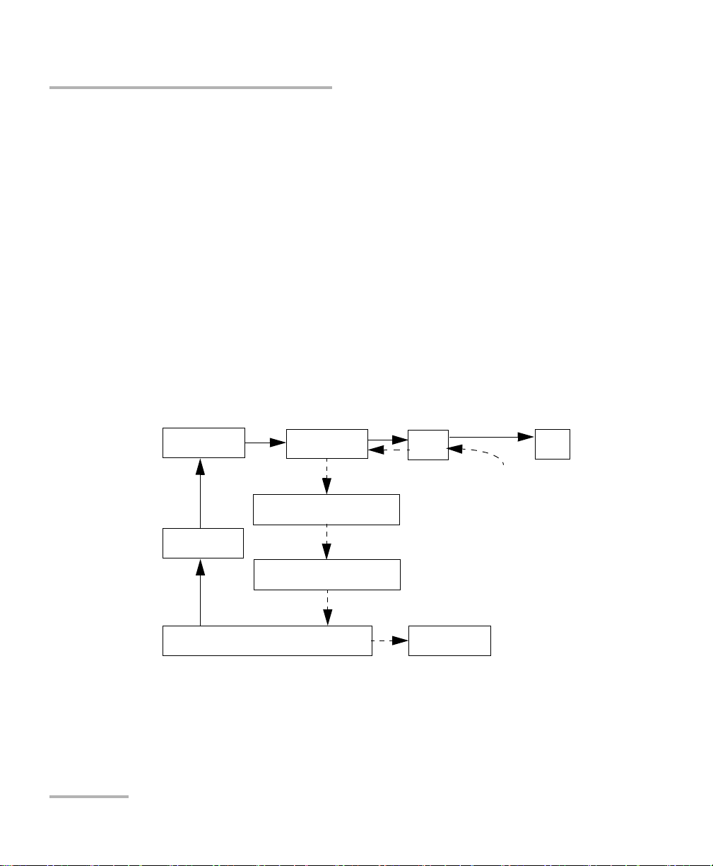
Microprocessor
Pulse
generator
Avalanche
photodetector (APD)
Display
Reflections come back
to the OTDR
Set of
instructions
Light pulses
Light pulses
Analog-to-digital
converter (A/D)
Returned signal
Analyzed signal
Laser
diode
Optical
coupler
OTDR
port
Fiber
OTDR Basic Principles
An OTDR uses the effects of Rayleigh scattering and Fresnel reflection to
measure the fiber’s condition, but the Fresnel reflection is tens of
thousands of times greater in power level than the backscatter.
Rayleigh scattering occurs when a pulse travels down the fiber and
small variations in the material, such as variations and discontinuities
in the index of refraction, cause light to be scattered in all directions.
However, the phenomenon of small amounts of light being reflected
directly back toward the transmitter is called backscattering.
Fresnel reflections occur when the light traveling down the fiber
encounters abrupt changes in material density that may occur at
connections or breaks where an air gap exists. A very large quantity of
light is reflected, as compared with the Rayleigh scattering. The
strength of the reflection depends on the degree of change in the index
of refraction.
When the full trace is displayed, each point represents an average of many
sampling points. You will have to zoom to see each point.
6 FTB-700 Series
Page 15
Introducing the FTB-700 OTDR
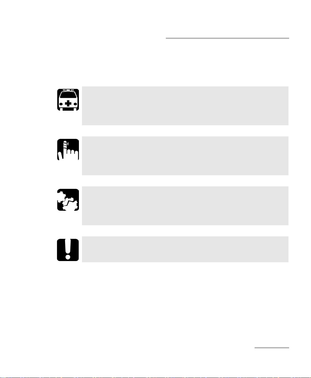
Conventions
Before using the product described in this guide, you should understand
the following conventions:
WARNING
Indicates a potentially hazardous situation which, if not avoided,
could result in death or serious injury. Do not proceed unless you
understand and meet the required conditions.
CAUTION
Indicates a potentially hazardous situation which, if not avoided,
may result in minor or moderate injury. Do not proceed unless you
understand and meet the required conditions.
CAUTION
Indicates a potentially hazardous situation which, if not avoided,
may result in component damage. Do not proceed unless you
understand and meet the required conditions.
Conventions
IMPORTANT
Refers to information about this product you should not overlook.
OTDR 7
Page 16

Page 17
2 Safety Information
General Safety Information
WARNING
Do not install or terminate fibers while a light source is active.
Never look directly into a live fiber and ensure that your eyes are
protected at all times.
WARNING
The use of controls, adjustments and procedures other than those
specified herein may result in exposure to hazardous situations or
impair the protection provided by this unit.
IMPORTANT
When you see the following symbol on your unit , make sure
that you refer to the instructions provided in your user
documentation. Ensure that you understand and meet the required
conditions before using your product.
IMPORTANT
Other safety instructions relevant for your product are located
throughout this documentation, depending on the action to
perform. Make sure to read them carefully when they apply to your
situation.
OTDR 9
Page 18
Safety Information
Other Safety Symbols on Your Unit
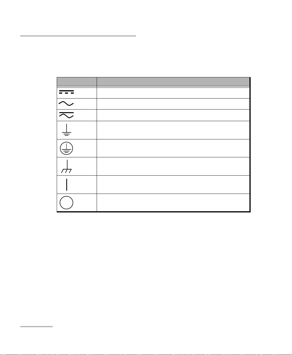
Other Safety Symbols on Your Unit
One or more of the following symbols may also appear on your unit.
Symbol Meaning
Direct current
Alternating current
Both direct and alternating current
The unit is equipped with an earth (ground) terminal.
The unit is equipped with a protective conductor terminal.
The unit is equipped with a frame or chassis terminal.
On (Power)
Off (Power)
10 FTB-700 Series
Page 19
Safety Information
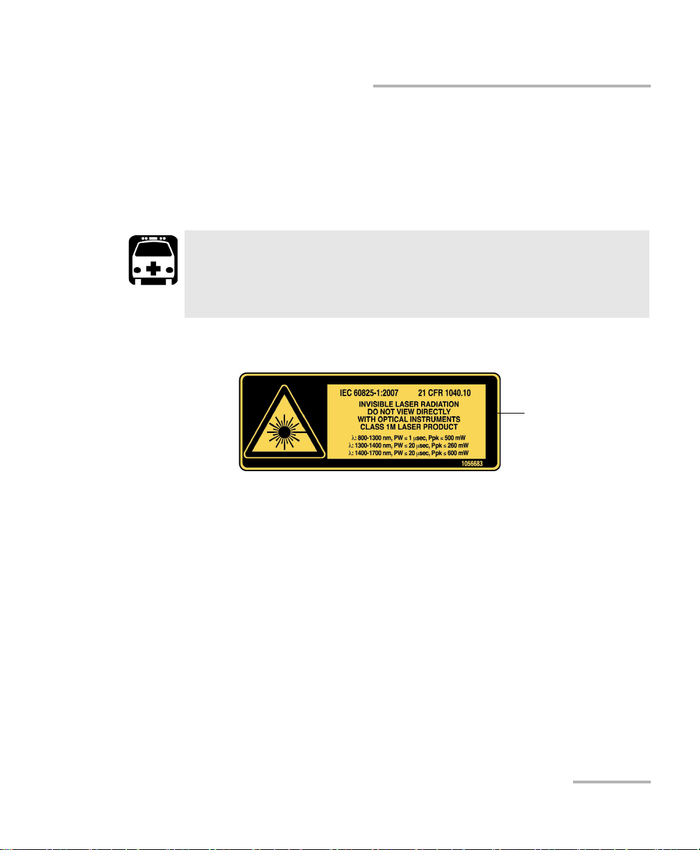
Affixed to module’s
side panel
Laser Safety Information
Laser Safety Information
Your instrument is a Class 1M laser product in compliance with standards
IEC 60825-1: 2007 and 21 CFR 1040.10, except for deviations pursuant to
Laser Notice No. 50, dated June 24, 2007. Invisible laser radiation may be
encountered at the output port.
WARNING
Viewing the laser output with certain optical instrument (for
example, eye loupes, magnifiers, and microscopes) within a
distance of 100 mm may pose an eye hazard.
The following label(s) indicate that the product contains a Class 1M source:
For more information on product safety and equipment ratings, refer to the
user documentation of your platform.
OTDR 11
Page 20

Page 21

3 Getting Started with Your
OTDR
Inserting and Removing Test Modules
CAUTION
Never insert or remove a module while the FTB-1 is turned on. This
will result in immediate and irreparable damage to both the
module and unit.
CAUTION
To avoid damaging your unit, use it only with modules approved by
EXFO.
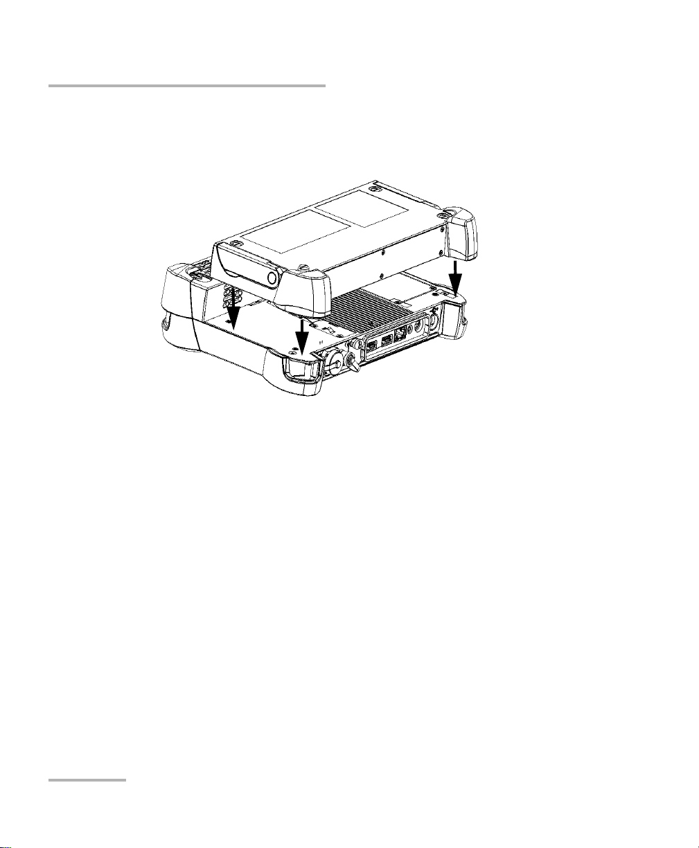
To insert a module into the FTB-1:
1. Turn off your unit (Shutdown).
2. Position the unit so that its front panel rests on a flat surface such as a
table.
OTDR 13
Page 22
Getting Started with Your OTDR
Inserting and Removing Test Modules
Place the module on the platform making sure that the bumpers and the
shorter sides of the module are flush with those of the platform. If
necessary, slightly move the module until alignment is correct.
14 FTB-700 Series
Page 23
Getting Started with Your OTDR
Turn screws
clockwise
Back panel
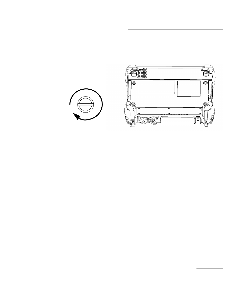
Inserting and Removing Test Modules
3. Using a flat screwdriver, turn the screws (4) clockwise until they are
tightened.
This will secure the module into its “seated” position.
When you turn on the unit, the startup sequence will automatically detect
the module.
OTDR 15
Page 24
Getting Started with Your OTDR
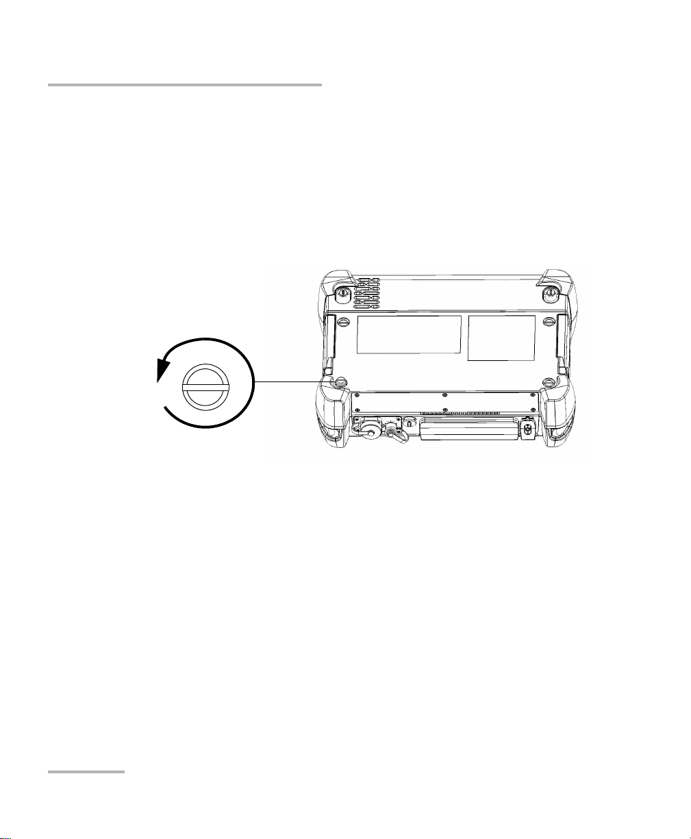
Turn screws
counterclockwise
Back panel
Inserting and Removing Test Modules
To remove a module from the FTB-1:
1. Turn off your unit (Shutdown).
2. Position the unit so that its front panel rests on a flat surface such as a
table.
3. Using a flat screwdriver, turn the screws (4) counterclockwise until
they are loose. Since they are captive screws, you cannot remove them
completely.
16 FTB-700 Series
Page 25
Getting Started with Your OTDR
Inserting and Removing Test Modules
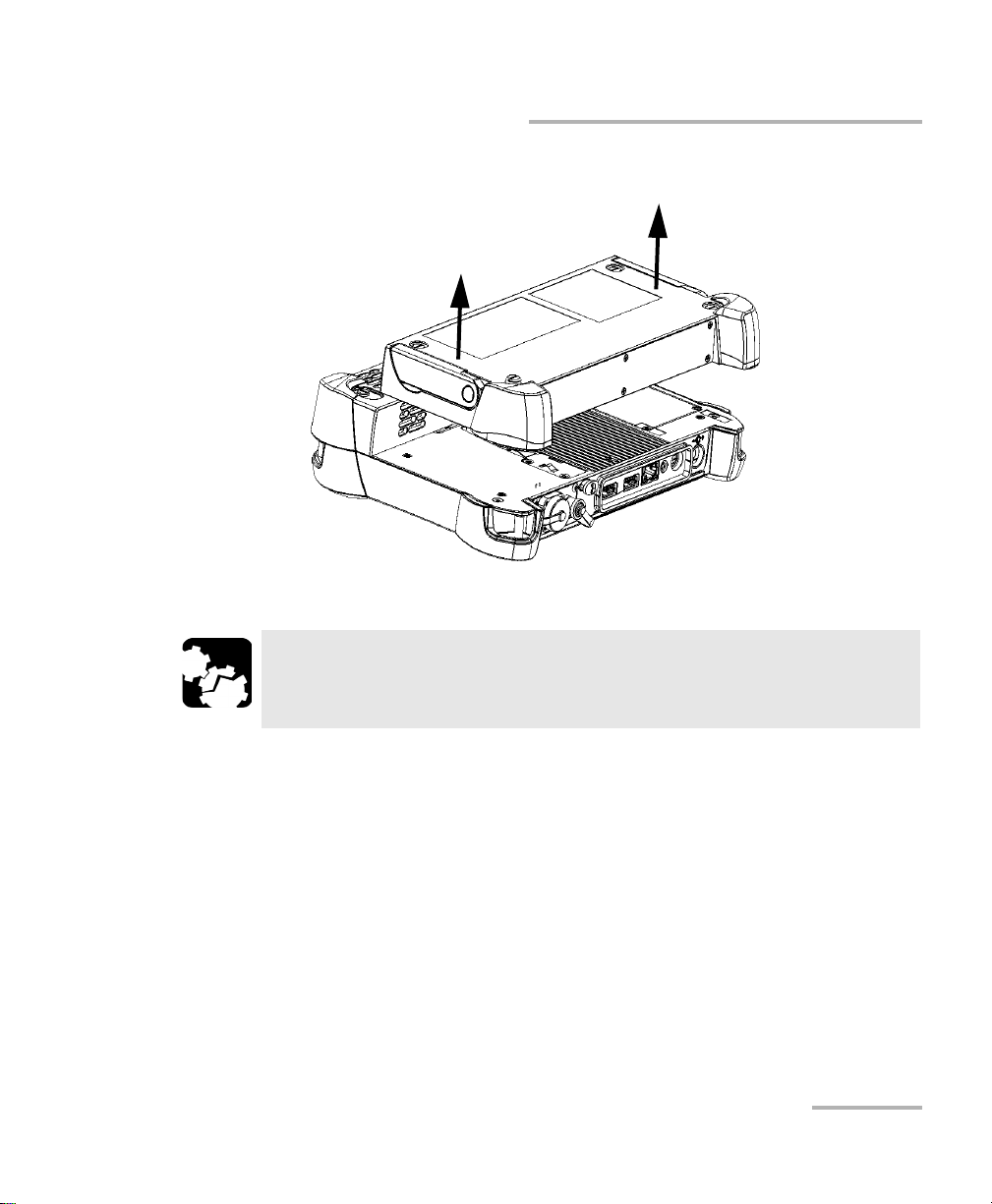
4. Hold the module by its sides (NOT by the connectors) and pull it up.
CAUTION
Pulling a module by its connectors could seriously damage both the
module and connector. Always pull a module by its casing.
OTDR 17
Page 26
Starting Module Applications
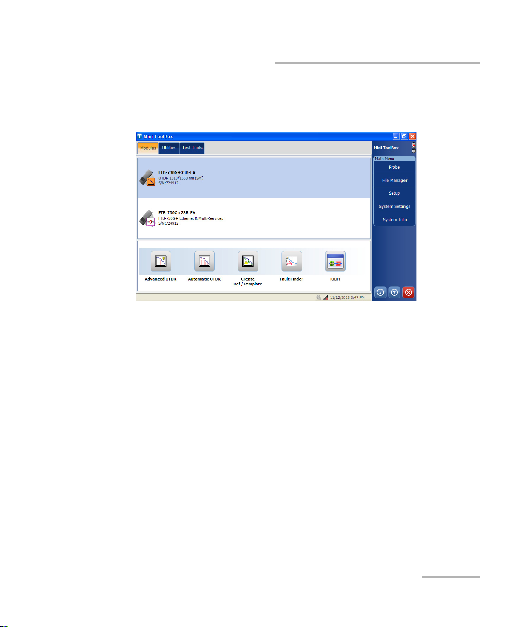
Starting Module Applications
Your modules can be configured and controlled from their dedicated
applications in Mini ToolBox.
To start a module application:
From Mini ToolBox, at the bottom of the window, press the button
corresponding to the desired application.
18 FTB-700 Series
Page 27
Starting Module Applications
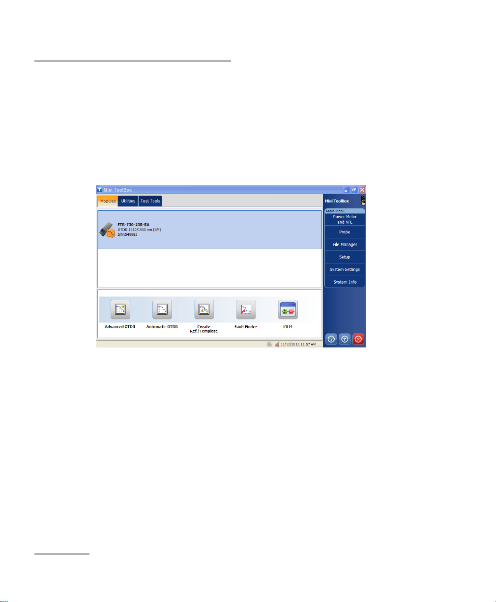
For the FTB-700G Series, from Mini ToolBox, select the OTDR module,
then press the button corresponding to the desired application. Only one
application can run at a time, either NetBlazer or one OTDR application.
Note: To start the NetBlazer application, refer either to the Transport Application
user guide or to the Ethernet/Packet Sync/FC/Wireless user guide for more
information.
OTDR 19
Page 28
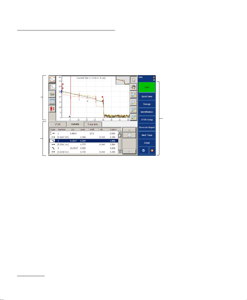
Timer
Data
display
Function
Ta bs
Button bar
To start the Power Meter or Probe application:
From Main Menu, press Power Meter or Probe.
The main window (shown below) contains all the commands required to
control the OTDR:
Note: Due to screen resolution, the appearance of your OTDR application may
vary slightly from the illustrations presented in this user guide.
Timer
Once the acquisition has begun, a timer is displayed on the right-hand side
of the screen, indicating the remaining time until the next acquisition.
20 FTB-700 Series
Page 29
4 Preparing Your OTDR for a Test
Bare metal
(or blue border)
indicates UPC
option
Green border
indicates APC
option
2 3 4
Installing the EXFO Universal Interface (EUI)
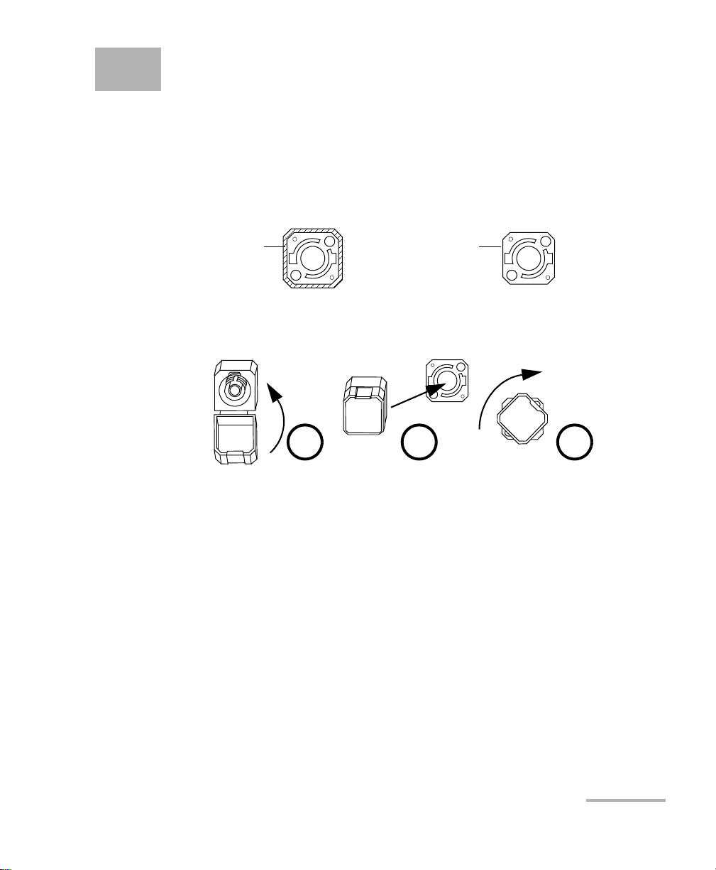
The EUI fixed baseplate is available for connectors with angled (APC) or
non-angled (UPC) polishing. A green border around the baseplate
indicates that it is for APC-type connectors.
To install an EUI connector adapter onto the EUI baseplate:
1. Hold the EUI connector adapter so the dust cap opens downwards.
2. Close the dust cap in order to hold the connector adapter more firmly.
3. Insert the connector adapter into the baseplate.
4. While pushing firmly, turn the connector adapter clockwise on the
baseplate to lock it in place.
OTDR 21
Page 30

Preparing Your OTDR for a Test
Cleaning and Connecting Optical Fibers
Cleaning and Connecting Optical Fibers
To ensure maximum power and to avoid erroneous readings:
Always inspect fiber ends and make sure that they are clean as
explained below before inserting them into the port. EXFO is
not responsible for damage or errors caused by bad fiber
cleaning or handling.
Ensure that your patchcord has appropriate connectors. Joining
mismatched connectors will damage the ferrules.
To connect the fiber-optic cable to the port:
1. Inspect the fiber using a fiber inspection microscope. If the fiber is
clean, proceed to connecting it to the port. If the fiber is dirty, clean it as
explained below.
2. Clean the fiber ends as follows:
IMPORTANT
2a. Gently wipe the fiber end with a lint-free swab dipped in isopropyl
alcohol.
2b. Use compressed air to dry completely.
2c. Visually inspect the fiber end to ensure its cleanliness.
22 FTB-700 Series
Page 31

Preparing Your OTDR for a Test
Cleaning and Connecting Optical Fibers
3. Carefully align the connector and port to prevent the fiber end from
touching the outside of the port or rubbing against other surfaces.
If your connector features a key, ensure that it is fully fitted into the
port’s corresponding notch.
4. Push the connector in so that the fiber-optic cable is firmly in place,
thus ensuring adequate contact.
If your connector features a screwsleeve, tighten the connector
enough to firmly maintain the fiber in place. Do not overtighten, as this
will damage the fiber and the port.
Note: If your fiber-optic cable is not properly aligned and/or connected, you will
notice heavy loss and reflection.
EXFO uses good quality connectors in compliance with EIA-455-21A
standards.
To keep connectors clean and in good condition, EXFO strongly
recommends inspecting them with a fiber inspection probe before
connecting them. Failure to do so will result in permanent damage to the
connectors and degradation in measurements.
OTDR 23
Page 32

Preparing Your OTDR for a Test
Naming Trace Files Automatically
Naming Trace Files Automatically
Each time you start an acquisition, the application suggests a file name
based on autonaming settings. This file name appears on the upper part of
the graph and the linear view.
The file name is made of a static part (alphanumeric) and a variable part
(numeric) that will be incremented or decremented, according to your
selection, as follows:
If you choose incrementation... If you choose decrementation...
Variable part increases until it
reaches the highest possible value
with the selected number of digits
(for example, 99 for 2 digits), then
restarts at 0.
After saving a result, the unit prepares the next file name by incrementing
(or decrementing) the suffix.
Note: If you choose not to save a particular trace file, the suggested file name will
remain available for the next trace you acquire.
This function is particularly useful when working in Template mode or
when testing multiple-fiber cables.
If you deactivate the automatic file naming function, the application will
prompt you to specify a file name. The default file name is Unnamed.trc.
By default, traces are saved in native (.trc) format, but you can configure
your unit to save them in Bellcore (.sor) format (see Selecting the Default
File Format on page 89).
Variable part decreases until it
reaches 0, then restarts at the highest
possible value with the selected
number of digits (for example, 99 for
2 digits).
24 FTB-700 Series
Page 33

Preparing Your OTDR for a Test
Naming Trace Files Automatically
Note: If you select the Bellcore (.sor) format, the unit will create one file per
wavelength (for example, TRACE001_1310.sor and TRACE001_1550.sor, if
you included both 1310 nm and 1550 nm in your test). The native format
contains all wavelengths in a single file.
To configure the automatic file naming:
1. From the button bar, press OTDR Setup.
2. Select the Acquisition tab.
3. Press Default Trace Information.
OTDR 25
Page 34

Preparing Your OTDR for a Test
Number of digits
composing the
variable part
Value at which the
autonumbering
sequence starts
The variable part will
increase or decrease
depending on your
choice
Naming Trace Files Automatically
4. Fill out the required information in the corresponding boxes and select
the direction for your trace files.
5. Press the button appearing next to the Fiber ID box to change the
contents of the fiber identification.
6. Change the criteria as needed, then press OK to confirm your new
settings and return to the Default Trace Information window.
26 FTB-700 Series
Page 35

Preparing Your OTDR for a Test
This preview is
updated
automatically as you
make your selections
Items that can be
included in the file
name
To select the separator in
the automatic
numbering section
To add personalized
information not included
in the filename criteria
To modify the order of appearance of the
selected components in the file name
Naming Trace Files Automatically
7. Press File Autonaming to set up the trace file name options.
8. In the File Name window, select the desired components to include in
the file name. You can change the order of apparition with the up and
down arrow buttons.
OTDR 27
9. Press OK to confirm your new settings.
Page 36

Preparing Your OTDR for a Test
Enabling or Disabling the First Connector Check
Enabling or Disabling the First Connector
Check
Note: This function is available in all OTDR modes. However, the first connector
check parameter used in Fault Finder mode is independent from the one
used in the other OTDR modes (Auto, Advanced and Template).
The first connector check feature is used to verify that the fibers are
properly connected to the OTDR. It verifies the injection level and displays
a message when an unusually high loss occurs at the first connection,
which could indicate that no fiber is connected to the OTDR port. By
default, this feature is not enabled.
Note: The first connector check is only performed when you test at singlemode
wavelengths.
To enable or disable the first connector check:
1. From the Main Menu, press OTDR Setup then press the General tab.
2. To enable the first connector check, select the First connector check
box.
OR
To disable it, clear the box.
28 FTB-700 Series
Page 37

Preparing Your OTDR for a Test
Setting Macrobend Parameters
Setting Macrobend Parameters
Note: This function is available with the Auto Diagnostic (AD) optional software
package only.
Note: This function is available both in Advanced and Auto modes.
Your unit can locate macrobends by comparing the loss values measured
at a certain location, for a certain wavelength (for example, 1310 nm) with
the loss values measured at the corresponding location, but for a greater
wavelength (for example, 1550 nm).
The unit will identify a macrobend when comparing two loss values if:
Of the two loss values, the greater loss occurred at the greater
wavelength.
AND
The difference between the two loss values exceeds the defined delta
loss value. The default delta loss value is 0.5 dB (which is suitable for
most fibers), but you can modify it.
You can also disable macrobend detection.
Note: Macrobend detection is only possible with singlemode wavelengths.
Filtered wavelengths or wavelengths of dedicated OTDR ports are not
available for macrobend detection.
For information on how the information about macrobends is available
after an acquisition, see Linear View on page 104 and Summary Table on
page 106.
OTDR 29
Page 38

Preparing Your OTDR for a Test
Setting Macrobend Parameters
To set macrobend parameters:
1. From the Main Menu, press OTDR Setup then select the General tab.
2. To enable the macrobend detection, select the Show macrobend
check box.
OR
To disable it, clear the check box.
3. If necessary, set the delta value as follows:
3a. From the Wavelengths list, select the pair of wavelengths for
which you want to define the delta value.
Only the combinations of wavelengths your module can support
will be available.
For more significant results, EXFO recommends to always select
the combination of wavelengths including the smallest possible
wavelength and the greatest wavelength (for example, if your
module supports 1310 nm, 1550 nm, and 1625 nm, you would
select the 1310 nm/1625 nm combination).
3b. In the Delta (loss) box, enter the desired value.
3c. Repeat steps 3a and 3b for all combinations of wavelengths.
To revert to default settings:
1. Press Default.
2. When the application prompts you, answer Yes if you want to apply the
settings to all combinations of wavelengths.
30 FTB-700 Series
Page 39

5 Testing Fibers in Auto Mode
Auto mode automatically evaluates fiber length, sets acquisition
parameters, acquires traces, and displays event tables and acquired traces.
In Auto mode, you can set the following parameters directly:
Test w a ve lengt h s ( all selected by default)
Fiber type (singlemode, singlemode live, or multimode) for models
supporting these fiber types
Autorange acquisition time
IOR (group index), RBS coefficient and helix factor
For all other parameters, the application uses those defined in Advanced
mode, except that analysis is always performed after acquisitions.
If you ever need to modify other parameters, go to Advanced mode (see
Testing Fibers in Advanced Mode on page 35 and Preparing Your OTDR for
a Test on page 21).
In Auto mode, the application will automatically evaluate the best settings
according to the fiber link currently connected to the unit (in less than
5 seconds). If you interrupt it, no data will be displayed.
Fiber characteristics are evaluated only once per session. Other fibers you
connect to, within the same cable, will be tested with the same settings.
When you start testing another link, you can reset these parameters.
Once this evaluation is complete, the application starts acquiring the trace.
The trace display is continually updated.
Note: You can interrupt the acquisition at any time. The application will display
the information acquired to that point.
OTDR 31
Page 40

Testing Fibers in Auto Mode
Event
pane
Tra ce
display
Once the acquisition is complete or interrupted, the analysis starts for
acquisitions of 5 seconds or more.
After analysis, the trace is displayed and events appear in the events table.
The application will also display status messages if you have selected to
display pass/fail messages (see Setting Pass/Fail Thresholds on page 50).
You can save the trace after analysis. If former results have not been saved
yet, the application prompts you to save them before starting a new
acquisition.
32 FTB-700 Series
Page 41

Testing Fibers in Auto Mode
To acquire traces in Auto mode:
1. Clean the connectors properly.
2. Connect a fiber to the OTDR port.
If your unit is equipped with two OTDR ports, ensure that you connect
the fiber to the appropriate port (singlemode, singlemode live, or
multimode), depending on the wavelength you intend to use.
CAUTION
Never connect a live fiber to the OTDR port without a proper setup.
Any incoming optical power ranging from –65 dBm to –40 dBm will
affect the OTDR acquisition. The way the acquisition will be
affected depends on the selected pulse width.
Any incoming signal greater than 10 dBm could damage your OTDR
permanently. For live-fiber testing, refer to the SM Live port
specifications for the characteristics of the built-in filter.
3. Set the autorange acquisition time (see Setting the Autorange
Acquisition Time on page 40).
4. Go to the OTDR tab.
5. If your OTDR supports singlemode, singlemode live, or multimode
wavelengths, under Wavelengths, from the list, select the desired fiber
type (for live-fiber testing, select SM Live; for C fiber, select 50 μm and
for D fiber, select 62.5 μm).
OTDR 33
Page 42

Testing Fibers in Auto Mode
6. Select the boxes corresponding to the desired test wavelengths. You
must select at least one wavelength.
7. If you want to clear the settings the OTDR has determined to start with
a new set of OTDR settings, press Reset.
8. Press Start or from the keypad.
If the first connector check feature is enabled, a message will appear if
there is a problem with the injection level (see Enabling or Disabling
the First Connector Check on page 28).
9. Once the analysis is complete, save the trace by pressing Quick Save
in the button bar.
The application will use a file name based on the autonaming
parameters you defined (see Naming Trace Files Automatically on
page 24). This file name appears at the top of the graph and at the top
of the linear view table.
Note: The application will only display the Save File dialog box if you have
activated the feature to always be prompted when you save a file. From
this dialog box, you can change the location, the file name and the file
format.
9a. If necessary, change the folder to which the file will be saved by
pressing the Location button.
9b. If necessary, specify a file name.
IMPORTANT
If you specify the name of an existing trace, the original file will be
overwritten and only the new file will be available.
10. Press OK to confirm.
34 FTB-700 Series
Page 43

6 Testing Fibers in Advanced
Mode
Advanced mode offers all the tools you need to perform complete OTDR
tests and measurements manually and gives you control over all test
parameters.
Note: Most parameters can only be set if you select Advanced mode first. Once
you have finished selecting your settings, you can simply return to the test
mode you prefer.
By default, in Advanced mode, all available test wavelengths are selected.
In this mode, you can either set the acquisition parameters yourself or let
the application determine the most appropriate values.
In the latter case, the application will automatically evaluate the best
settings according to the fiber link currently connected to the unit:
The pulse width will be determined using a factory-defined
signal-to-noise ratio (SNR) requirement specified where the
End-of-Fiber (EoF) event has been detected.
The EoF event detection algorithm uses the end-of-fiber threshold
defined in the tab of the application setup. If you are not sure about
which value to choose, revert to the factory default value for this
parameter.
The range will then be set automatically. This optimum value may
differ from the values currently associated with the Distance dial of the
main window. In this case, the application will “add” the required
value and mark it with a * symbol.
The application uses the acquisition time defined in the Acquisition
tab of the OTDR setup (for more information, see Setting the Autorange
Acquisition Time on page 40). The default value is 15 seconds. Longer
acquisitions give better OTDR results.
OTDR 35
Page 44

Testing Fibers in Advanced Mode
Event
pane
Tra ce
display
Although the application sets the acquisition parameters, you can modify
these values as needed, even while the acquisition is in progress. The
OTDR simply restarts the averaging each time a modification is made.
Note: You can interrupt the acquisition at any time. The application will display
the information acquired to that point.
Once the acquisition is complete or interrupted, the analysis starts for
acquisitions of 5 seconds or more.
After analysis, the trace is displayed. Events appear both in the events table
and in the linear view (if you purchased the optional software package).
The application will also display pass/fail messages if you have selected
this feature. For more information, see Setting Pass/Fail Thresholds on
page 50.
You can save the trace after analysis. If former results have not been saved
yet, the application prompts you to save them before starting a new
acquisition.
36 FTB-700 Series
Page 45

Testing Fibers in Advanced Mode
To acquire traces:
1. Clean the connectors properly (see Cleaning and Connecting Optical
Fibers on page 22).
2. Connect a fiber to the OTDR port.
If your unit is equipped with two OTDR ports, ensure that you connect
the fiber to the appropriate port (singlemode, singlemode live, or
multimode), depending on the wavelength you intend to use.
CAUTION
Never connect a live fiber to the OTDR port without a proper setup.
Any incoming optical power ranging from –65 dBm to –40 dBm will
affect the OTDR acquisition. The way the acquisition will be
affected depends on the selected pulse width.
Any incoming signal greater than 10 dBm could damage your OTDR
permanently. For live-fiber testing, refer to the SM Live port
specifications for the characteristics of the built-in filter.
3. If you want the application to provide automatic acquisition values, set
the autorange acquisition time (see Setting the Autorange Acquisition
Time on page 40).
4. If you want to set your own IOR (group index), RBS coefficient or helix
factor, see Setting the IOR, RBS Coefficient, and Helix Factor on
page 41.
5. Go to the OTDR tab.
6. If you want to test in high resolution, simply select the feature (see
Enabling the High-Resolution Feature on page 46).
OTDR 37
Page 46

Testing Fibers in Advanced Mode
7. If your OTDR supports singlemode, singlemode live, or multimode
wavelengths, under Wavelengths, from the list, select the desired fiber
type (for live-fiber testing, select SM Live; for C fiber, select 50 μm and
for D fiber, select 62.5 μm).
8. Select the boxes corresponding to the desired test wavelengths. You
must select at least one wavelength.
9. Select the desired distance, pulse, and time values. For more
information, see Setting Distance Range, Pulse Width, and Acquisition
Time on page 43.
10. Press Start or from the keypad. If the first connector
check feature is enabled, a message will appear if there is a problem
with the injection level (see Enabling or Disabling the First Connector
Check on page 28).
You can modify the acquisition parameters as needed, while the
acquisition is in progress. The OTDR simply restarts the averaging each
time a modification is made.
38 FTB-700 Series
Page 47

Testing Fibers in Advanced Mode
11. Once the analysis is complete, save the trace by pressing Quick Save
in the button bar.
The application will use a file name based on the autonaming
parameters you defined (see Naming Trace Files Automatically on
page 24). This file name appears at the top of the graph and at the top
of the linear view table.
Note: The application will only display the Save File dialog box if you have
activated the feature to always be prompted when you save a file. From
this dialog box, you can change the location, the file name and the file
format.
11a.If necessary, change the folder to which the file will be saved by
pressing the Location button.
11b.If necessary, specify a file name.
IMPORTANT
If you enter the name of an existing trace, the original file will be
replaced with the new file.
12. Press OK to confirm.
OTDR 39
Page 48

Testing Fibers in Advanced Mode
Setting the Autorange Acquisition Time
Setting the Autorange Acquisition Time
Note: This function is available both in Advanced and Auto modes.
When performing automatic acquisitions in Advanced mode (see Testing
Fibers in Advanced Mode on page 35) or before activating Auto mode (see
Testing Fibers in Auto Mode on page 31), you can set an autorange
acquisition time for the OTDR to average acquisitions over a set time
period.
The application uses this value to determine the best settings for the test.
Note: In Template mode, the acquisition time of the reference trace is used for all
trace acquisitions, not the autorange acquisition time.
To set the autorange acquisition time:
1. From the button bar, press OTDR Setup then go to the Acquisition tab.
2. Go to the Autorange acquisition time box and press the up or down
arrow to select your preference. The default value is 30 seconds.
3. Press Exit OTDR Setup to return to the OTDR application.
40 FTB-700 Series
Page 49

Testing Fibers in Advanced Mode
Setting the IOR, RBS Coefficient, and Helix Factor
Setting the IOR, RBS Coefficient, and Helix
Factor
Note: This function is available both in Advanced and Auto modes.
You s ho u ld s et t he I O R ( g rou p in dex ) , RBS coefficient and helix factor
before performing tests in order to apply them to all newly acquired traces.
However, if you are in Advanced mode, you can also set them at a later
time in the Trace Info. tab to reanalyze a specific trace.
The index of refraction (IOR) value (also known as group index) is
used to convert time-of-flight to distance. Having the proper IOR is
crucial for all OTDR measurements associated with distance (event
position, attenuation, section length, total length, etc.). IOR is provided
by the cable or fiber manufacturer.
The test application determines a default value for each wavelength.
You can set the IOR value for each available wavelength. You should
verify this information before each test.
The Rayleigh backscatter (RBS) coefficient represents the amount of
backscatter in a particular fiber. The RBS coefficient is used in the
calculation of event loss and reflectance, and it can usually be
obtained from the cable manufacturer.
The test application determines a default value for each wavelength.
You can set the RBS coefficient for each available wavelength.
The helix factor takes into consideration the difference between the
length of the cable and the length of the fiber inside the cable. Fibers
within a cable are spiraling around the cable core. The helix factor
describes the pitch of that spiral.
By setting the helix factor, the length of the OTDR distance axis is
always equivalent to the physical length of the cable (not the fiber).
OTDR 41
Page 50

Testing Fibers in Advanced Mode
Wavelength for which
RBS and IOR will be
defined
Index of refraction
Rayleigh backscatter
coefficient
Setting the IOR, RBS Coefficient, and Helix Factor
To set the IOR, RBS, and helix factor parameters:
1. From the button bar, press OTDR Setup.
2. From the OTDR Setup window, go to the Acquisition tab.
3. Use the up or down arrow located on the side of the wavelength box to
select the desired wavelength.
IMPORTANT
Change the default RBS coefficient only if you have values provided
by the fiber manufacturer. If you set this parameter incorrectly, your
reflectance measurements will be inaccurate.
4. Select the default settings by pressing Default. When the application
prompts you, answer Yes only if you want to apply the new settings to
all wavelengths.
OR
Enter your own values in the boxes, for each available wavelength.
Note: You cannot define a different helix factor for each wavelength. This value
takes into account the difference between the length of the cable and the
length of the fiber inside the cable; it does not vary with wavelengths.
42 FTB-700 Series
5. Press Exit OTDR Setup.
Page 51

Testing Fibers in Advanced Mode
Setting Distance Range, Pulse Width, and Acquisition Time
Setting Distance Range, Pulse Width, and
Acquisition Time
The distance range, pulse width and acquisition time are set with the
controls in the Advanced main window.
Distance: corresponds to the distance range of the fiber span to be
tested according to the selected measurement units (see Selecting the
Distance Units on page 93).
Changing the distance range alters the available settings of the pulse
width and leaves only the settings available for the specified range. You
can select either Auto or one of the predefined values.
You can customize the available distance range values (see
Customizing the Acquisition Distance Range Values on page 95). If you
select Auto, the application will evaluate the fiber length and set the
acquisition parameters accordingly.
Pulse: corresponds to the pulse width for the test. A longer pulse
allows you to probe further along the fiber, but results in less
resolution. A shorter pulse width provides higher resolution, but less
distance range. The available distance ranges and pulse widths
depend on your OTDR model.
Note: Not all pulse widths are compatible with all distance ranges.
You can select either Auto or one of the predefined values.
If you select Auto, the application will evaluate the fiber type and length
and set the acquisition parameters accordingly.
OTDR 43
Page 52

Testing Fibers in Advanced Mode
Setting Distance Range, Pulse Width, and Acquisition Time
Time: corresponds to the acquisition duration (period during which
results will be averaged). Generally, longer acquisition times generate
cleaner traces (this is especially true with long-distance traces)
because as the acquisition time increases, more of the noise is
averaged out. This averaging increases the signal-to-noise ratio (SNR)
and the OTDR’s ability to detect small events.
The time settings will also determine how the timer (displayed in the
toolbar) counts time during testing (see Timer on page 39).
If the predefined values do not suit your needs, you can customize one
or all of them. For more information, see Customizing the Acquisition
Time Values on page 97.
In addition to the displayed values, the following time modes are
available:
Real: used to immediately view changes in the fiber under test. In
this mode, the SNR of the trace is lower and the trace is refreshed
instead of averaged until you press Stop.
You can alternate between real mode and averaging time interval
mode while an acquisition is in progress.
Note: The Real item will be available if only one wavelength is selected.
Auto: the application will use the autorange acquisition time that
you have previously defined (see Setting the Autorange Acquisition
Time on page 40). It will also evaluate the fiber type and length and
set the acquisition parameters accordingly.
You can use the same distance range, pulse width and acquisition time
parameters for testing at all wavelengths on a multiwavelength OTDR.
IMPORTANT
To test using the high-resolution feature, the acquisition time must
be of at least 15 seconds.
44 FTB-700 Series
Page 53

Testing Fibers in Advanced Mode
Parameter-setting dials
Selection
marker
Setting Distance Range, Pulse Width, and Acquisition Time
To set the parameters:
From the OTDR tab:
Press the dial corresponding to the parameter you wish to set (the
selection marker will move clockwise).
OR
Press directly the value to select it. The selection marker will go to that
value immediately.
If you want the application to provide automatic acquisition values, move
at least one dial to the Auto position. The other dials are automatically set
accordingly.
Note: If your OTDR supports singlemode, singlemode live, or multimode
wavelengths, settings would be applied to either singlemode, singlemode
live, or multimode wavelengths, depending on the selected fiber type
(same settings for 50 μm and 62.5 μm).
OTDR 45
Page 54

Testing Fibers in Advanced Mode
Enabling the High-Resolution Feature
To use the same pulse and acquisition time for all wavelengths:
1. From the button bar, press OTDR Setup, then go to the Acquisition
tab.
2. Select the Apply settings to all wavelengths box.
The modifications you make to pulse, time, and range settings will now be
applied to all wavelengths.
Enabling the High-Resolution Feature
You can select the high-resolution feature to obtain more data points per
acquisition. This way, the data points will be closer to each other, which
will result in a greater distance resolution for the trace.
Note: When you test with the high-resolution feature, you should use a longer
averaging time to maintain a signal-to-noise ratio (SNR) that will be
equivalent to the one you would have got with the standard resolution.
Note: You can use high resolution with any test mode (except when you monitor
fiber in real time), but you must be in Advanced mode to select it. In
Template mode, you will have to acquire the reference trace using high
resolution. This way, all subsequent acquisitions will use this feature
automatically.
IMPORTANT
To test using the high-resolution feature, the acquisition time must
be of at least 15 seconds.
46 FTB-700 Series
Page 55

Testing Fibers in Advanced Mode
Enabling the High-Resolution Feature
To enable the high-resolution feature:
1. From the button bar, press OTDR Setup.
2. Go to the Acquisition tab.
3. Select the High-resolution acquisition box.
Note: If your OTDR supports singlemode, singlemode live, or multimode
wavelengths, the high-resolution feature will be activated either for the
singlemode, singlemode live, or multimode wavelengths, depending on the
selected fiber type.
4. Press Exit OTDR Setup to return to the main window.
OTDR 47
Page 56

Testing Fibers in Advanced Mode
Enabling or Disabling Analysis After Acquisition
Enabling or Disabling Analysis After
Acquisition
The OTDR trace acquisition procedure will be completed by the analysis.
You can either choose to automatically analyze each trace immediately
after the acquisition, or perform the analysis whenever it suits you best.
When the analysis process is disabled, the Event table of a newly acquired
trace will be empty.
You can also set a default fiber span, which will be applied during the
analysis of all traces to display test results. For details, see Setting a Default
Span Start and Span End on page 55.
Note: In Auto mode, the application always performs an analysis after the
acquisition.
48 FTB-700 Series
Page 57

Testing Fibers in Advanced Mode
Enabling or Disabling Analysis After Acquisition
To enable or disable the analysis after trace acquisition:
1. From the button bar, press OTDR Setup.
2. Go to the Analysis tab.
3. If you want the OTDR to automatically analyze an acquired trace,
select the Automatically analyze data after acquisition box.
If you clear the check box, the trace will be acquired without being
analyzed.
Note: By default, traces are automatically analyzed as they are acquired.
4. Press Exit OTDR Setup to return to the main window.
OTDR 49
Page 58

Testing Fibers in Advanced Mode
Setting Pass/Fail Thresholds
Setting Pass/Fail Thresholds
You can activate and set Pass/Fail threshold parameters for your tests.
You can set thresholds for splice loss, connector loss, reflectance, fiber
section attenuation, span loss, span length, and span ORL. You can apply
the same pass/fail thresholds to all test wavelengths or apply them
separately to each one.
You can set different pass/fail thresholds for each available test
wavelength. These pass/fail thresholds will be applied to the analysis
results of all newly acquired traces with the corresponding wavelength.
By default, the application provides threshold values for the following
wavelengths: 1310 nm, 1383 nm, 1390 nm, 1410 nm, 1490 nm, 1550 nm,
1625 nm, and 1650 nm. However, if you work with files containing other
wavelengths, the application will automatically add these custom
wavelengths to the list of available wavelengths. You will then be able to
define thresholds for these new wavelengths. You can revert all thresholds
to their default values, except if they are associated with custom
wavelengths.
The loss, reflectance and attenuation thresholds that you set are applied to
all events where such values can be measured. Setting these thresholds
allows you either to ignore events with known lower values, or to ensure
that all events are detected—even the ones for which very small values are
measured.
50 FTB-700 Series
Page 59

Testing Fibers in Advanced Mode
Setting Pass/Fail Thresholds
The following table provides the default, minimum and maximum
thresholds.
Test Default Minimum Maximum
Splice loss (dB) 1.000 0.015 5.000
Connector loss (dB) 1.000 0.015 5.000
Fiber section attenuation (dB/km) 0.400 0.000 5.000
Once the thresholds are set, the application will be able to perform
Pass/Fail tests to determine the status of the various events (pass or fail).
The Pass/Fail test is performed on two occasions:
when analyzing or reanalyzing a trace
when you open a trace file
Values that are greater than the predefined thresholds are displayed in
white on a red background in the events table.
The Pass/Fail threshold LED, located on the front of the unit, will also
indicate the status (green for pass, red for fail).
You can also set the application to display pass/fail messages when the
Pass/Fail test is performed.
OTDR 51
Page 60

Testing Fibers in Advanced Mode
Threshold to set
Value associated
with the
threshold to set
Setting Pass/Fail Thresholds
To set pass/fail thresholds:
1. From the button bar, select OTDR Setup, then select the Event Table
tab.
2. From the Wave l e n gth list, select the wavelength for which you want to
set thresholds.
3. Select the boxes corresponding to the thresholds that you want to use,
and enter the desired values in the appropriate fields.
Note: If you no longer want the application to take into account a particular
threshold, simply clear the corresponding box.
4. If you want the application to display messages when events fail the
test, select Display Pass/Fail message.
52 FTB-700 Series
Page 61

Testing Fibers in Advanced Mode
Setting Pass/Fail Thresholds
5. If you want to apply the thresholds you have just defined to one or
several other wavelengths, proceed as follows:
5a. Press the Copy to Other Wavelengths button.
5b. Select the boxes corresponding to the wavelengths for which you
want to use the same thresholds.
Note: You can use the Select All button to quickly select all boxes at the same
time.
5c. Press OK to confirm you selection.
6. Press Exit OTDR Setup to return to the main window.
OTDR 53
Page 62

Testing Fibers in Advanced Mode
Setting Pass/Fail Thresholds
To revert to default threshold values and to delete custom
wavelengths:
1. From the button bar, select OTDR Setup, then select the Event Table
tab.
2. Press the Revert to Factory Settings button.
3. When the application prompts you, confirm the modification with Yes .
All threshold values of all wavelengths are returned to their default values,
except for thresholds that are associated with custom wavelengths.
When you revert thresholds to their default values, custom
wavelengths will be deleted from the list of available wavelengths,
except if a file using at least one of these wavelengths is still open.
IMPORTANT
54 FTB-700 Series
Page 63

Testing Fibers in Advanced Mode
Setting a Default Span Start and Span End
Setting a Default Span Start and Span End
By default, the span start and span end of a fiber are assigned, respectively,
to the first event (the launch level event) and the last event (often a
non-reflective or reflective end event) of a trace.
You can change the default fiber span that will be applied during the initial
trace analysis.
You can set the span start and span end on a particular event or at a certain
distance value from the beginning or end of the trace. You can even define
a fiber span for short fibers by placing the span start and the span end on
the same event.
By default, the number of available events is set to 10 and, therefore,
does not necessarily reflect the actual number of events displayed.
When you set a distance value for the span start or end, the application
searches for a nearby event. If it finds one, the span start or end is
assigned to that event, rather than at the exact distance you have set.
Changes to the span start and span end will modify the contents of the
events table. The span start becomes event 1 and its distance reference
becomes 0. Events excluded from the fiber span are grayed out in the
events table, and do not appear in the trace display. The cumulative loss is
calculated within the defined fiber span only.
Note: You can also change the fiber span of a single trace after the analysis and
reanalyze the trace (see Analyzing or Reanalyzing a Trace on page 149).
However, if you want to keep working with the original parameters, you
must reenter them.
OTDR 55
Page 64

Testing Fibers in Advanced Mode
Setting a Default Span Start and Span End
To change the default span start and span end for traces:
1. From the button bar, press OTDR Setup.
2. From the OTDR Setup window, go to the Analysis tab.
3. If you want to set the span start and end with a distance value, under
Span start and Span end, select Set by distance.
Go to the Position box and enter the desired value, using the distance
units displayed to the right of the box.
Under Span end, indicate whether the span end position is from the
fiber span start or from the end of the fiber.
OR
If you want to set the span start and end on a particular event, under
Span start and Span end, select Set on event.
From the Event number list, use the up or down arrow to select the
number of the event that you want to designate as span start or span
end.
The span event parameters are applied to all newly acquired traces.
56 FTB-700 Series
Page 65

7Testing Fibers in Template
Mode (optional)
Note: This function is available with the optional Event Characterization (EC)
software package only.
Template mode allows you to test fibers and compare them to a reference
trace that was previously acquired and analyzed.
Template Principle
Cables contain numerous fibers. Theoretically, on all these fibers, you will
find the same events at the same location (due to connectors, splices,
etc.). Template mode allows you to test these fibers one after the other
quickly and efficiently and ensures that no event remains undetected.
The Template mode concept is to acquire a reference trace (template),
add information and comments on the current job, then save the trace.
For a more accurate reference trace, you can update it with new events
that may occur during the first acquisitions (up to fifteen).
The test application will flag possible problems and discrepancies between
the reference trace and other traces.
Each new acquisition will be compared to the reference trace and the
software will mark and measure any missing event.
If the reference trace was created with the ToolBox software on an
FTB-500 or a computer, the event-related comments inserted in the
reference trace, as well as the reference trace report, are automatically
copied to subsequent traces.
Note: You cannot add comments to events or to a reference trace.
OTDR 57
Page 66

Testing Fibers in Template Mode (optional)
Restrictions of Template Mode
You can save the trace after analysis. If former results have not been saved
yet, the application prompts you to save them before starting a new
acquisition.
Template mode can be used on an unlimited number of traces, as long as
you have at least one reference trace. Thus, you can use Template mode to
automate trace acquisition.
Restrictions of Template Mode
To speed up trace acquisition in Template mode, certain restrictions apply.
The parameters used to acquire the reference trace are automatically
applied when acquiring subsequent traces (including the
high-resolution feature, when applicable).
The reference trace and subsequent traces must be acquired using
identical wavelength(s), but pulse settings can be adjacent and still be
accepted.
The OTDR that you intend to use must support at least one wavelength
that was used to acquire the reference trace.
The reference trace and subsequent traces (or recalled traces) must
respect the following criteria:
58 FTB-700 Series
Page 67

Testing Fibers in Template Mode (optional)
Reference trace pulse
4
---------------------------------------------------
Current trace pulse
Reference trace pulse
Current trace pulse
Current trace pulse Reference trace pulse 4
Reference trace pulse
Current trace pulse
Cu rrent trace pulse
4
------------------------------------------------
Reference trace pulse
Reference trace pulse
Current trace pulse
Reference trace pulse Current trace pulse 4
Reference trace pulse Current trace pulse
Item To be valid...
Pulse width Must be:
OR
Restrictions of Template Mode
Pulse width
This would also be valid:
OR
Fiber types Compare singlemode traces with singlemode traces.
Number of
events
Acquisition
mode
Traces must have at least two events (span start and span end) and a
fiber section.
Reference trace must not be acquired in Real mode (see Setting Distance
Range, Pulse Width, and Acquisition Time on page 43).
Wavelengths Reference wavelengths and wavelengths of subsequent (or reloaded)
traces must be identical.
When you process traces using an OTDR, you acquire the traces as you go
along. When you process traces on a computer, you use traces stored on
disk; therefore, applying the span length is optional.
OTDR 59
Page 68

Testing Fibers in Template Mode (optional)
Acquiring the Reference Trace
Acquiring the Reference Trace
You must acquire a reference trace before you start the Template mode.
The acquisition parameters you define for this reference trace will be used
to acquire subsequent traces.
To acquire the reference trace:
1. Clean the connectors properly (see Cleaning and Connecting Optical
Fibers on page 22).
2. Connect a fiber to the OTDR port.
If your unit is equipped with two OTDR ports, ensure that you connect
the fiber to the appropriate port (singlemode, singlemode live, or
multimode), depending on the wavelength you intend to use.
CAUTION
Never connect a live fiber to the OTDR port without a proper setup.
Any incoming optical power ranging from –65 dBm to –40 dBm will
affect the OTDR acquisition. The way the acquisition will be
affected depends on the selected pulse width.
Any incoming signal greater than 10 dBm could damage your OTDR
permanently. For live-fiber testing, refer to the SM Live port
specifications for the characteristics of the built-in filter.
3. Acquire a trace in Auto or Advanced test mode. If you want to test
using high resolution, you will have to select this feature before
acquiring the reference trace. For more information, see Testing Fibers
in Auto Mode on page 31 or Testing Fibers in Advanced Mode on
page 35.
4. If necessary, define the span start and end (see Analyzing the Fiber on
a Specific Fiber Span on page 151).
60 FTB-700 Series
Page 69

Testing Fibers in Template Mode (optional)
Acquiring the Reference Trace
5. Once the analysis is complete, save the trace by pressing Quick Save
in the button bar.
The application will use a file name based on the autonaming
parameters you defined (see Naming Trace Files Automatically on
page 24). This file name appears at the top of the graph and at the top
of the linear view table.
Note: The application will only display the Save File dialog box if you have
activated the feature to always be prompted when you save a file. From
this dialog box, you can change the location, the file name and the file
format.
OTDR 61
Page 70

Testing Fibers in Template Mode (optional)
Acquiring Traces in Template Mode
Acquiring Traces in Template Mode
To acquire traces in Template mode, you must first open your reference
trace in the application.
If you want your reference trace to be more accurate, you can update it
with the new events that might be found.
The application will automatically switch to Template mode once the
reference update is complete, that is, after 15 acquisitions or after you stop
the update manually.
To acquire traces in Template mode:
1. If necessary, clean the connectors (see Cleaning and Connecting
Optical Fibers on page 22) and connect a fiber to the OTDR port.
If your unit is equipped with two OTDR ports, ensure that you connect
the fiber to the appropriate port (singlemode, singlemode live, or
multimode), depending on the wavelength you intend to use.
CAUTION
Never connect a live fiber to the OTDR port without a proper setup.
Any incoming optical power ranging from –65 dBm to –40 dBm will
affect the OTDR acquisition. The way the acquisition will be
affected depends on the selected pulse width.
Any incoming signal greater than 10 dBm could damage your OTDR
permanently. For live-fiber testing, refer to the SM Live port
specifications for the characteristics of the built-in filter.
2. When the application prompts you, select the trace you want to use as
the reference trace. If you do not select it immediately, you will have to
select it manually before starting your test (see Selecting a Reference
Trace on page 69). By default, all wavelengths are selected, but you
can adjust the selection to your needs.
62 FTB-700 Series
Page 71

Testing Fibers in Template Mode (optional)
3. Set test parameters.
3a. From the button bar, press OTDR Setup.
3b. Select the Create Ref./Template tab.
Acquiring Traces in Template Mode
If necessary, select Create reference trace to update your
reference trace for the next acquisitions.
This mode will use the first 15 traces (or less, if you stop the
process manually) to continue compiling events.
Note: You can disable the mode by clearing the Create reference trace box
between two acquisitions.
OTDR 63
Page 72

Testing Fibers in Template Mode (optional)
Acquiring Traces in Template Mode
IMPORTANT
Once the first 15 acquisitions have been performed, or if you stop
the reference update manually, the only way to reactivate it will be
to close the application and start a new acquisition in Template
mode.
3c. Set the Template mode option you want to use on the current
trace acquisition:
Consider only the events already indicated on the reference trace
and ignore any other event occurring on the current trace.
Keep all the events on the current trace, whether they are on the
reference trace or not. You can delete these events later.
3d. Press Exit OTDR Setup to return to the main window.
3e. If you selected Create reference trace at step 4b, update your
reference trace as follows:
3f. Press Start or from the keypad.
If the first connector check feature is enabled, a message will
appear if there is a problem with the injection level (see Enabling
or Disabling the First Connector Check on page 28).
All traces will automatically be acquired and analyzed, and the
events will be identified.
64 FTB-700 Series
Page 73

Testing Fibers in Template Mode (optional)
Acquiring Traces in Template Mode
4. If applicable, the application will display the number of new events
detected for each wavelength.
4a. Press OK to close the dialog box.
Note: You can only add events to the reference trace during reference update.
Note: If you chose the Keep all events feature for the acquisitions that will be
performed after the update, you may find it useful to add newly detected
events to obtain a more accurate reference trace.
OTDR 65
Page 74

Testing Fibers in Template Mode (optional)
Acquiring Traces in Template Mode
5. Question marks will appear in the Event table to identify new events
not found on the reference trace. If you want to add these marked
events to the reference trace, press Add to Ref. You can also delete
unwanted events with the Delete button.
Asterisks (“*”) identify events that were not found on the main trace,
but that were added because they exist on the reference trace.
Question marks identify events found on the main trace that do not
exist on the reference trace. Numbers will be assigned to new events
when the trace is analyzed.
Asterisks and question marks are used to identify events without
modifying the existing event numbers. This way, you can match the
events of the reference trace with those of the main trace more easily.
Note: If you select the Analyze Reference Events Only feature (from OTDR
setup), the Add to Ref. and Delete buttons are unavailable. Events that are
not on the reference trace, but that are detected on the acquired trace, are
deleted.
5a. Once the analysis is complete, save the trace by pressing
Quick Save in the button bar.
The application will use a file name based on the autonaming
parameters you defined (see Naming Trace Files Automatically on
page 24). This file name appears at the top of the graph and at the
top of the linear view table.
66 FTB-700 Series
Page 75

Testing Fibers in Template Mode (optional)
Acquiring Traces in Template Mode
Note: The application will only display the Save File dialog box if you have
activated the feature to always be prompted when you save a file. From
this dialog box, you can change the location, the file name and the file
format.
5b. Repeat steps 3f to 5a as necessary to update your reference trace.
6. Once the reference update is complete (or if you did not select the
reference update), the application automatically switches to Template
mode. New events will be managed according to the option you
selected at step 3c. Perform acquisitions in Template mode as follows:
6a. Press Start or from the keypad.
If the first connector check feature is enabled, a message will
appear if there is a problem with the injection level (see Enabling
or Disabling the First Connector Check on page 28).
All traces will automatically be acquired and analyzed, and the
events will be identified.
6b. The application will prompt you if new events are found.
OTDR 67
Page 76

Testing Fibers in Template Mode (optional)
Acquiring Traces in Template Mode
6c. Once the analysis is complete, save the trace by pressing
Quick Save in the button bar.
The application will use a file name based on the autonaming
parameters you defined (see Naming Trace Files Automatically on
page 24). This file name appears at the top of the graph and at the
top of the linear view table.
Note: The application will only display the Save File dialog box if you have
activated the feature to always be prompted when you save a file. From
this dialog box, you can change the location, the file name and the file
format.
6d. Repeat steps 3c to 6c as necessary.
68 FTB-700 Series
Page 77

Testing Fibers in Template Mode (optional)
Selecting a Reference Trace
Selecting a Reference Trace
In Templ at e OTDR mode, you can only select a file as a reference trace.
This operation is closely related to opening a trace file. All the traces, will
be displayed using the zoom and markers settings saved along with the
reference trace file (see Opening Trace Files on page 156).
Note: The following procedure will be useful if you did not select a reference
trace file when the Open Reference Trace File dialog box appeared during
the activation of Template OTDR mode or if you want to use another
reference trace.
To select a reference trace:
1. From the Main Menu window, press Storage, then Open Reference.
2. If necessary, select the storage location from where you want to open
the file.
3. Select the file to be used as a reference and press OK.
The application opens the selected trace file automatically.
OTDR 69
Page 78

Page 79

8 Testing Fibers in Fault Finder
Mode
The application offers you a special testing feature to rapidly locate fiber
ends. It also displays the length of the fiber under test.
This could be useful if you want to perform a quick test without having to
set all the acquisition parameters.
Acquiring Traces in Fault Finder Mode
The unit will determine the more appropriate wavelength (singlemode or
multimode, depending on your test configuration). It will use the default
IOR (group index), RBS coefficient, and helix factor. The duration of
acquisition is 45 seconds.
To acquire traces in Fault finder mode:
1. Clean the connectors properly (see Cleaning and Connecting Optical
Fibers on page 22).
2. Connect a fiber to the OTDR port.
If your unit is equipped with two OTDR ports, ensure that you connect
the fiber to the appropriate port (singlemode, singlemode live, or
multimode), depending on the wavelength you intend to use.
CAUTION
Never connect a live fiber to the OTDR port without a proper setup.
Any incoming optical power ranging from –65 dBm to –40 dBm will
affect the OTDR acquisition. The way the acquisition will be
affected depends on the selected pulse width.
Any incoming signal greater than 10 dBm could damage your OTDR
permanently. For live-fiber testing, refer to the SM Live port
specifications for the characteristics of the built-in filter.
OTDR 71
Page 80

Testing Fibers in Fault Finder Mode
Acquiring Traces in Fault Finder Mode
3. From the Port list, specify to which port you connected your fiber.
4. Press Start or from the keypad. If the first connector
check feature is enabled, a message will appear if there is a problem
with the injection level (see Enabling or Disabling the First Connector
Check for Fault Finder on page 81).
72 FTB-700 Series
Page 81

Testing Fibers in Fault Finder Mode
Acquiring Traces in Fault Finder Mode
5. Once the analysis is complete, save the trace by pressing Quick Save
in the button bar.
The application will use a file name based on the autonaming
parameters you defined (see Naming Fault Finder Files Automatically
on page 74). This file name appears at the top of the graph.
Note: The application will only display the Save File dialog box if you have
activated the feature to always be prompted when you save a file and if
you did not disable the storage features. From the Save File dialog box, you
can change the location, the file name and the file format.
5a. If necessary, change the folder to which the file will be saved by
pressing the Location button.
5b. If necessary, specify a file name.
IMPORTANT
If you specify the name of an existing trace, the original file will be
overwritten and only the new file will be available.
5c. Press OK to confirm.
OTDR 73
Page 82

Testing Fibers in Fault Finder Mode
Naming Fault Finder Files Automatically
Naming Fault Finder Files Automatically
Each time you start an acquisition, the Fault Finder application suggests a
file name based on autonaming settings. This file name appears on the
upper part of the graph.
Note: The autonaming settings used in Fault Finder mode are independent from
those used in Auto, Advanced or Template modes. File names are built
following the same principle, but there is one set of settings for Fault Finder
and one set of settings for the other OTDR modes.
The file name is made of a static part (alphanumeric) and a variable part
(numeric) that will be incremented or decremented, according to your
selection, as follows:
If you choose incrementation... If you choose decrementation...
Variable part increases until it
reaches the highest possible value
with the selected number of digits
(for example, 99 for 2 digits), then
restarts at 0.
After saving a result, the unit prepares the next file name by incrementing
(or decrementing) the suffix.
Note: If you choose not to save a particular trace file, the suggested file name will
remain available for the next trace you will acquire.
By default, traces are saved in native (.trc) format, but you can configure
your unit to save them in Bellcore (.sor) format (see Selecting the Default
File Format for the Fault Finder Traces on page 76).
74 FTB-700 Series
Variable part decreases until it
reaches 0, then restarts at the highest
possible value with the selected
number of digits (for example, 99 for
2digits).
Page 83

Testing Fibers in Fault Finder Mode
Number of digits composing
the variable part
Static part Variable part (incremented)
The value appearing in this box will be used in
the next file name.
File name extension
(corresponds to the current file
format)
Naming Fault Finder Files Automatically
To configure the automatic file naming:
1. From the button bar, press Setup.
2. From the Setup window, select the General tab then press the File
Autonaming button.
3. From the Autonaming Setup dialog box, set the parameters.
If you want the variable part to increase each time a file is saved, select
Increment. If you want it to decrease, select Decrement.
4. Press OK to confirm your new settings.
OTDR 75
Page 84

Testing Fibers in Fault Finder Mode
Selecting the Default File Format for the Fault Finder Traces
Selecting the Default File Format for the Fault
Finder Traces
You can define the default file format the Fault Finder application will use
when you save your traces.
Note: The default file format used in Fault Finder mode are independent from the
file format used in Auto, Advanced or Template modes. There is one default
file format for Fault Finder and one default file format for the other OTDR
modes.
By default, traces are saved in native (.trc) format, but you can configure
your unit to save them in Bellcore (.sor) format.
You can only modify the file format from the Save File dialog box, which
means you need to save at least one trace in the desired format before it
becomes the new default file format.
Note: The application will only display this dialog box if you have activated the
feature to always be prompted when you save a file (see Enabling or
Disabling the Confirmation of Fault Finder File Name on page 78) and if
you did not disable the storage features.
76 FTB-700 Series
Page 85

Testing Fibers in Fault Finder Mode
Selecting the Default File Format for the Fault Finder Traces
To select the default file format:
1. From the button bar, press Quick Save.
2. From the Save File dialog box, select the desired format.
3. Press OK to save your file in the new format. The next files will be
saved in the new format.
OTDR 77
Page 86

Testing Fibers in Fault Finder Mode
Enabling or Disabling the Confirmation of Fault Finder File Name
Enabling or Disabling the Confirmation of
Fault Finder File Name
By default, each time you save a file, the application prompts you to
confirm the file name.
Note: The file name confirmation parameter used in Fault Finder mode is
independent from the one used in the other OTDR modes (Auto, Advanced
and Template).
The application will use a file name based on autonaming settings
(see Naming Fault Finder Files Automatically on page 74).
If you prefer to hide the Quick Save button, see Enabling or Disabling the
Storage Feature on page 80.
78 FTB-700 Series
Page 87

Testing Fibers in Fault Finder Mode
Enabling or Disabling the Confirmation of Fault Finder File Name
To enable or disable file name confirmation:
1. From the button bar, press Setup, then go to the General tab.
2. If you want to confirm file name each time you press Quick Save,
select the Always show confirmation window on save check box.
OR
If you never want to be prompted, clear the check box.
Note: You can also disable the confirmation of the file name by clearing the
Always show this window on save check box directly from the Save File
dialog box.
3. Press Exit Setup to return to the main window. The changes are
applied automatically.
OTDR 79
Page 88

Testing Fibers in Fault Finder Mode
Enabling or Disabling the Storage Feature
Enabling or Disabling the Storage Feature
By default, the Quick Save button is displayed in the button bar. However,
if you only want to perform quick tests without having to save the results,
you may prefer to hide the Quick Save button.
To enable or disable the storage feature:
1. From the button bar, press Setup, then go to the General tab.
2. If you want to hide the Quick Save button, select the
Disable storage features check box.
OR
If you want to display the button, clear the check box.
3. Press Exit Setup to return to the main window. The changes are
applied automatically.
80 FTB-700 Series
Page 89

Testing Fibers in Fault Finder Mode
Enabling or Disabling the First Connector Check for Fault Finder
Enabling or Disabling the First Connector
Check for Fault Finder
The first connector check feature is used to verify that the fibers are
properly connected to the OTDR. It verifies the injection level and displays
a message when a unusually high loss occurs at the first connection, which
could indicate that no fiber is connected to the OTDR port. By default, this
feature is not enabled.
Note: The first connector check is only performed when you test at singlemode
wavelengths.
Note: The first connector check parameter used in Fault Finder mode is
independent from the one used in the other OTDR modes (Auto, Advanced
and Template).
OTDR 81
Page 90
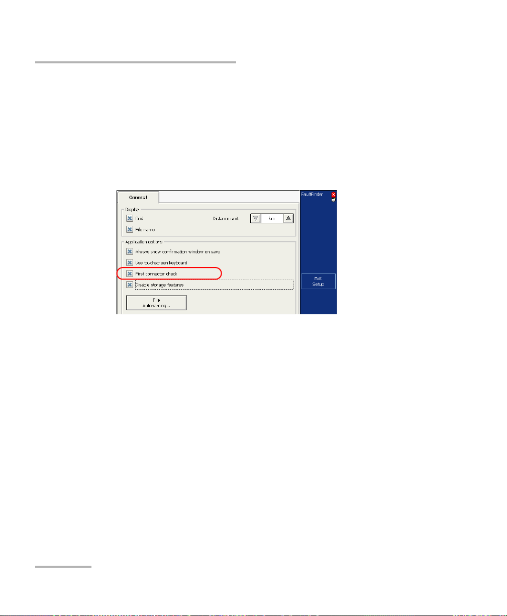
Testing Fibers in Fault Finder Mode
Enabling or Disabling the First Connector Check for Fault Finder
To enable or disable the first connector check:
1. From the button bar, press Setup then select the General tab.
2. To enable the first connector check, select the First connector check
check box.
OR
To disable it, clear the check box.
3. Press Exit Setup to return to the main window. The changes are
applied automatically.
82 FTB-700 Series
Page 91

Testing Fibers in Fault Finder Mode
Enabling or Disabling the Touchscreen Keyboard
Enabling or Disabling the Touchscreen
Keyboard
With the touchscreen keyboard, you can enter data without having to use
an external keyboard. By default, this feature is enabled.
When you select a text or number box, the touchscreen keyboard or
keypad appears automatically. However, you can disable it if you prefer
using an external keyboard.
Note: Hiding or displaying the touchscreen keyboard in Fault Finder mode has no
effect on the way the touchscreen keyboard will be used in the other OTDR
modes (Auto, Advanced and Template).
To enable or disable the touchscreen keyboard:
1. From the button bar, press Setup, then select the General tab.
2. If you want to display the touchscreen keyboard, select the
Use touchscreen keyboard check box.
OR
If you prefer to hide the keyboard, clear the check box.
3. Press Exit Setup to return to the main window. The changes are
applied automatically.
OTDR 83
Page 92

Testing Fibers in Fault Finder Mode
GridFile name
Setting Trace Display Parameters
Setting Trace Display Parameters
You can change several trace display parameters:
the grid: You can display or hide the grid appearing on the graph’s
background. By default, the grid is displayed.
the file name in the trace display: The file name appears at the top of
the trace display. By default, the file name is displayed.
Note: The trace display settings used in Fault Finder mode are independent from
the ones used in the other OTDR modes (Auto, Advanced and Template).
84 FTB-700 Series
Page 93

Testing Fibers in Fault Finder Mode
Setting Trace Display Parameters
To set the trace display parameters:
1. From the button bar, press the Setup button, then select the General
tab.
2. Select the check boxes corresponding to the item you want to display
on the graph.
OR
To hide them, clear the check boxes.
3. Press Exit Setup to return to the main window. The changes are
applied automatically.
OTDR 85
Page 94

Testing Fibers in Fault Finder Mode
Units used
Selecting the Distance Units
Selecting the Distance Units
You can select the distance units that will be used in the application.
The default distance units are the kilometers.
Note: The distance units used in Fault Finder mode are independent from the
ones used in the other OTDR modes (Auto, Advanced and Template).
86 FTB-700 Series
Page 95

Testing Fibers in Fault Finder Mode
Selecting the Distance Units
To select the distance units for your display:
1. From the button bar, select Setup.
2. From the Setup window, select the General tab.
3. From the Distance units list, select the item corresponding to the
desired units.
4. Press Exit Setup.
You return to the main window and the newly selected measurement
unit appears everywhere these units are used.
OTDR 87
Page 96

Page 97

9 Customizing Your OTDR
You can customize the appearance and behavior of your OTDR application.
Selecting the Default File Format
You can define the default file format the application will use when you
save your traces.
By default, traces are saved in native (.trc) format, but you can configure
your unit to save them in Bellcore (.sor) format.
If you select the Bellcore (.sor) format, the unit will create one file per
wavelength (for example, TRACE001_1310.sor and TRACE001_1550.sor, if
you included both 1310 nm and 1550 nm in your test). The native format
contains all wavelengths in a single file.
You can only modify the file format from the Save File dialog box, which
means you need to save at least one trace in the desired format before it
becomes the new default file format.
Note: The application will only display this dialog box if you have activated the
feature to always be prompted when you save a file (see Enabling or
Disabling File Name Confirmation on page 91).
OTDR 89
Page 98

Customizing Your OTDR
Selecting the Default File Format
To select the default file format:
1. From the Main Menu window, press Quick Save.
2. From the Save File dialog box, select the desired format.
3. Press OK to save your file in the new format.
The next files will be saved in the new format.
90 FTB-700 Series
Page 99

Customizing Your OTDR
Enabling or Disabling File Name Confirmation
Enabling or Disabling File Name Confirmation
By default, each time you save a file, the application prompts you to
confirm the file name.
The application will use a file name based on autonaming settings
(see Naming Trace Files Automatically on page 24).
Note: The file name confirmation parameter used in the Auto, Advanced, and
Template modes is independent from the one used in the Fault Finder
mode.
OTDR 91
Page 100

Customizing Your OTDR
Enabling or Disabling File Name Confirmation
To enable or disable file name confirmation:
1. From the Main Menu window, press OTDR Setup, then select the
General tab.
2. If you want to confirm file name each time you press Quick Save,
select the Always show confirmation window on save check box.
OR
If you never want to be prompted, clear the check box.
Note: You can also disable the confirmation of the file name by clearing the
Always show this window on save check box from the Save File dialog
box.
3. Press Exit OTDR Setup to return to the main window.
The changes are applied automatically.
92 FTB-700 Series
 Loading...