

Page 1
FTB-635
Wideband Copper and DSL Test Module
User Guide
Page 2

Copyright Information
Copyright Information
Copyright © 2012–2014 EXFO Inc. All rights reserved. No part of this
publication may be reproduced, stored in a retrieval system or transmitted
in any form, be it electronically, mechanically, or by any other means such
as photocopying, recording or otherwise, without the prior written
permission of EXFO Inc. (EXFO).
Information provided by EXFO is believed to be accurate and reliable.
However, no responsibility is assumed by EXFO for its use nor for any
infringements of patents or other rights of third parties that may result from
its use. No license is granted by implication or otherwise under any patent
rights of EXFO.
EXFO’s Commerce And Government Entities (CAGE) code under the North
Atlantic Treaty Organization (NATO) is 0L8C3.
The information contained in this publication is subject to change without
notice.
Trademarks
EXFO’s trademarks have been identified as such. However, the presence
or absence of such identification does not affect the legal status of any
trademark.
Units of Measurement
Units of measurement in this publication conform to SI standards and
practices.
September 12, 2014
Version number: 6.0.0
ii FTB-635
Page 3

Contents
Copyright Information ............................................................................................................ii
Certification Information ......................................................................................................vii
1 Introducing the FTB-635 Wideband Copper and DSL Test Module ........... 1
Key Features and Benefits .......................................................................................................1
Typical Applications ................................................................................................................2
Software Options ....................................................................................................................3
Conventions ............................................................................................................................4
2 Safety Information ....................................................................................... 5
Electrical Safety Information ...................................................................................................6
Equipment Ratings .................................................................................................................7
3 Getting Started ............................................................................................ 9
Starting Module Applications .................................................................................................9
Cable Connections ................................................................................................................10
Inserting and Removing Test Modules .................................................................................12
Performing FTB-1 Software Updates .....................................................................................17
Usual Tab Elements ...............................................................................................................19
4 Advanced WB Copper Application ............................................................ 21
Using the Graphical User Interface .......................................................................................21
Main Window .......................................................................................................................21
Status Bar .............................................................................................................................22
Title Bar ................................................................................................................................23
Test Information and Control ................................................................................................23
Main Menu ...........................................................................................................................23
Application buttons ..............................................................................................................24
5 Copper Tests: Using the Main Menu ......................................................... 27
Start/Stop Button ..................................................................................................................27
Cable Book ...........................................................................................................................28
Phone Book ..........................................................................................................................36
Dialer ....................................................................................................................................46
Config/Profile ........................................................................................................................50
Application Settings .............................................................................................................66
Factory Default .....................................................................................................................73
Save Test ...............................................................................................................................74
Copper and xDSL Tests iii
Page 4

6 Reading and Exporting Saved Results .......................................................79
Result File .............................................................................................................................79
Reading the Result File ..........................................................................................................80
Export Results .......................................................................................................................87
7 Pair Detective Test ......................................................................................89
Pair Detective ........................................................................................................................89
Multimeter ............................................................................................................................96
TDR .......................................................................................................................................97
Summary ..............................................................................................................................98
8 Auto Test ......................................................................................................99
POTS Auto Test .....................................................................................................................99
Summary ............................................................................................................................104
User Auto Test .....................................................................................................................105
Summary ............................................................................................................................113
9 FaultMapper Test ......................................................................................115
FaultMapper .......................................................................................................................115
TDR .....................................................................................................................................120
Summary ............................................................................................................................121
10 Multimeter Tests .......................................................................................123
Multimeter Main Page ........................................................................................................124
Voltage Test ........................................................................................................................125
Current Test ........................................................................................................................134
Resistance Test ....................................................................................................................143
Capacitance/Opens Test ......................................................................................................150
Resistive Balance Test ..........................................................................................................157
Balance Test ........................................................................................................................161
11 Multimeter 2 Tests ....................................................................................169
Multimeter 2 Main Page .....................................................................................................169
Isolation Test .......................................................................................................................170
Locator Tone Test ................................................................................................................176
Load Coils Test ....................................................................................................................179
Station Ground ...................................................................................................................182
12 TDR Test .....................................................................................................187
Auto TDR ............................................................................................................................188
Manual TDR ........................................................................................................................191
Xtalk TDR ............................................................................................................................199
Summary ............................................................................................................................202
iv FTB-635
Page 5

13 RFL Test ..................................................................................................... 203
RFL-2-Wire ...........................................................................................................................203
RFL-4-Wire ...........................................................................................................................206
RFL-K-Test ............................................................................................................................209
Setting Cable Parameters ....................................................................................................212
Summary ............................................................................................................................214
14 Signal Test ................................................................................................. 215
Signal Main Page ................................................................................................................215
WB Balance Test ..................................................................................................................216
WB Attenuation Test ...........................................................................................................222
TX/RX Tone Test ...................................................................................................................228
15 Noise Tests ................................................................................................ 235
Noise Main Page .................................................................................................................235
VF Noise Test .......................................................................................................................236
Power Influence Test ...........................................................................................................241
WB PSD Noise Test ..............................................................................................................246
NEXT ...................................................................................................................................254
16 Impulse Tests ............................................................................................ 263
Impulse Main Page .............................................................................................................263
VF Impulse Noise Test .........................................................................................................265
WB Impulse Noise Test ........................................................................................................269
Impulse Scope Test ..............................................................................................................275
Impulse Duration ................................................................................................................282
17 Test Lead Compensation .......................................................................... 289
Summary ............................................................................................................................290
18 Copper Tests: Result Summary ................................................................ 291
Summary ............................................................................................................................291
19 xDSL Application ...................................................................................... 293
Using the Graphical User Interface .....................................................................................293
Main Window .....................................................................................................................294
Status Bar ...........................................................................................................................294
Title Bar ..............................................................................................................................295
Test Information and Control ..............................................................................................295
Main Menu .........................................................................................................................297
Settings ..............................................................................................................................299
Copper and xDSL Tests v
Page 6

20 xDSL Tests: Using the Main Menu ............................................................307
Start/Stop Button ................................................................................................................307
Config/Profile ......................................................................................................................308
Test Configuration ..............................................................................................................310
21 xDSL Test Results .......................................................................................319
Summary ............................................................................................................................319
DSL Information .................................................................................................................321
DSL Statistics ......................................................................................................................324
Band Information ...............................................................................................................327
DSL Graphs .........................................................................................................................329
Network Information ..........................................................................................................330
22 xDSL Tests: Saving and Reading Results ..................................................333
Saving a Test Result .............................................................................................................333
Read Result .........................................................................................................................334
Exports ...............................................................................................................................336
23 Maintenance ..............................................................................................339
Recalibrating the Unit .........................................................................................................340
Recycling and Disposal (Applies to European Union Only) ..................................................341
24 Troubleshooting ........................................................................................343
Solving Common Problems .................................................................................................343
Contacting the Technical Support Group ............................................................................345
Transportation ....................................................................................................................346
25 Warranty ....................................................................................................347
General Information ...........................................................................................................347
Liability ...............................................................................................................................348
Exclusions ...........................................................................................................................349
Certification ........................................................................................................................349
Service and Repairs .............................................................................................................350
EXFO Service Centers Worldwide ........................................................................................351
A Technical Specifications ............................................................................353
Index ...............................................................................................................359
vi FTB-635
Page 7

Certification Information
Certification Information
North America Regulatory Statement
This unit was certified by an agency approved in both Canada and the
United States of America. It has been evaluated according to applicable
North American approved standards for product safety for use in Canada
and the United States.
Electronic test and measurement equipment is exempt from FCC part 15,
subpart B compliance in the United States of America and from ICES-003
compliance in Canada. However, EXFO Inc. makes reasonable efforts to
ensure compliance to the applicable standards.
The limits set by these standards are designed to provide reasonable
protection against harmful interference when the equipment is operated in
a commercial environment. This equipment generates, uses, and can
radiate radio frequency energy and, if not installed and used in accordance
with the user guide, may cause harmful interference to radio
communications. Operation of this equipment in a residential area is likely
to cause harmful interference in which case the user will be required to
correct the interference at his own expense.
Modifications not expressly approved by the manufacturer could void the
user's authority to operate the equipment.
Copper and xDSL Tests vii
Page 8

Certification Information
European Community Declaration of Conformity
An electronic version of the declaration of conformity for your product is
available on our website at www.exfo.com. Refer to the product’s page on
the Web site for details.
viii FTB-635
Page 9

1 Introducing the FTB-635
Wideband Copper and DSL
Test Module
The FTB-635 Wideband Copper and DSL Test Module is designed for
testing ADSL2+ and VDSL2 services between the service provider and the
subscriber premises. The module also qualifies and troubleshoots the
copper-loop plant by using pass/fail-driven automated functionality. The
FTB-635 provides a comprehensive offering of test features such as, Pair
Detective, Auto Test, FaultMapper, Multimeter, TDR, RFL, Signal, Noise, and
DSL testing.
Key Features and Benefits
SmartR™ Automatic results analysis
High-voltage isolation testing
Wideband impulse noise scope/analysis
Ideal for FTTh repairs with platform built-in optical power meter
ADSL2+ and VDSL2 testing
Ethernet testing for verifying FTTx service at the customer premises
Copper and xDSL Tests 1
Page 10

Introducing the FTB-635 Wideband Copper and DSL Test Module
Typi c a l A pp licat i o ns
Typical Applications
Perfect for troubleshooting fiber-to-the-cab service
Complete suite of manual and automated advanced metallic tests
30 MHz wideband spectrum analysis
High-power isolation for finding resistive faults and insulation failures
Wideband impulse noise analysis
Optional ADSL2+ and VDSL2 bonding support
Powerful IPTV, VoIP, IP tests, web browser, and test utilities on the
platform enable a new level of services testing.
Leverages FTB-1 platform connectivity to capture and upload results
2 FTB-635
Page 11
Introducing the FTB-635 Wideband Copper and DSL Test Module
Software Options
Software Options
Software keys are available to enable additional services. For information
on how to install and activate software options, refer to the FTB-1 User
Guide.
Options Description
BOND ADSL2+/VDSL2 Bonding
HIVOLT Extends isolation resistance testing output
from 125 VDC to 500 VDC.
IDD Impulse Noise Duration and Disruption
Analysis
NEXT Near End Crosstalk
RFL Support for RFL test.
SmartR Pair Detective and FaultMapper tests;
both include TDR.
TDR Support for TDR test.
WBAND
Support for WB Balance and WB
Attenuation from Signal test.
Support for WB PSD Noise and WB
Impulse Noise from Noise Test.
VDSL2MOD VDSL2 Test support
VDSL2-STGR Ikanos CO4 support
Note: These options are also available as EXFO Connect floating options.
Copper and xDSL Tests 3
Page 12
Introducing the FTB-635 Wideband Copper and DSL Test Module
Conventions
Conventions
Before using the product described in this guide, you should understand
the following conventions:
WARNING
Indicates a potentially hazardous situation which, if not avoided,
could result in death or serious injury. Do not proceed unless you
understand and meet the required conditions.
CAUTION
Indicates a potentially hazardous situation which, if not avoided,
may result in minor or moderate injury. Do not proceed unless you
understand and meet the required conditions.
CAUTION
Indicates a potentially hazardous situation which, if not avoided,
may result in component damage. Do not proceed unless you
understand and meet the required conditions.
IMPORTANT
Refers to information about this product you should not overlook.
4 FTB-635
Page 13
2 Safety Information
WARNING
The use of controls, adjustments and procedures other than those
specified herein may result in exposure to hazardous situations or
impair the protection provided by this unit.
IMPORTANT
When you see the following symbol on your unit , make sure
that you refer to the instructions provided in your user
documentation. Ensure that you understand and meet the required
conditions before using your product.
IMPORTANT
Other safety instructions relevant for your product are located
throughout this documentation, depending on the action to
perform. Make sure to read them carefully when they apply to your
situation.
WARNING
Use only accessories that meet EXFO specifications.
Copper and xDSL Tests 5
Page 14

Safety Information
Electrical Safety Information
Electrical Safety Information
If you need to ensure that the unit is completely turned off, disconnect the
power cable and remove the batteries.
Use the external power supply indoors only.
Position the unit so that the air can circulate freely around it.
Operation of any electrical instrument around flammable gases
or fumes constitutes a major safety hazard.
To avoid electrical shock, do not operate the unit if any part of
the outer surface (covers, panels, etc.) is damaged.
Only authorized personnel should carry out adjustments,
maintenance or repair of opened units under voltage. A person
qualified in first aid must also be present. Do not replace any
components while power cable and battery are connected.
WARNING
Capacitors inside the unit may be charged even if the unit has
been disconnected from its electrical supply.
Use only the AC adapter/charger provided by EXFO with your
unit.
6 FTB-635
Page 15
Equipment Ratings
Equipment Ratings
Tem pe rat ur e
Operation 0 °C to 40 °C (32 °F to 104 °F)
Safety Information
Equipment Ratings
Maximum operation
3000 m (9842 ft)
altitude
For more information on product safety and equipment ratings, refer to the
user documentation of your platform.
Copper and xDSL Tests 7
Page 16

Page 17
3 Getting Started
The Wideband Copper and DSL Test Module applications are pre-installed
on the FTB-1. If the module is not already installed, refer to the FTB-1 User
Guide for more information on how to install the applications.
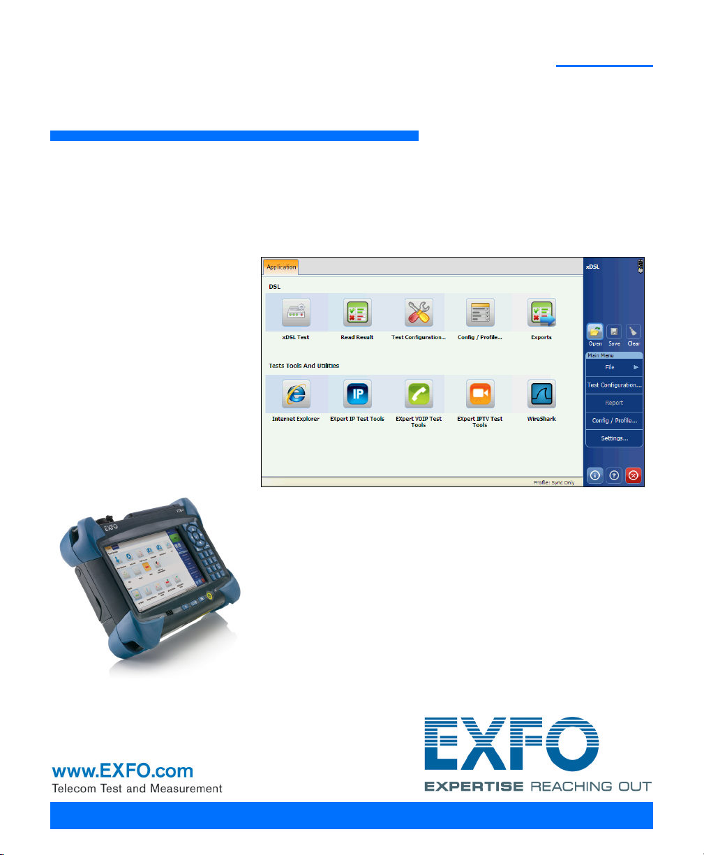
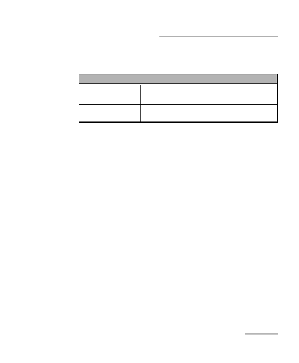
Starting Module Applications
The module can be configured and controlled by starting either the
Advanced WB Copper or xDSL application.
To start an application:
From the Mini Toolbox, press the desired application button.
Title Bar
The Title Bar displays the software application name and the battery level
indicator.
Exit Button
The Exit button is used to close the application.
Copper and xDSL Tests 9
Page 18
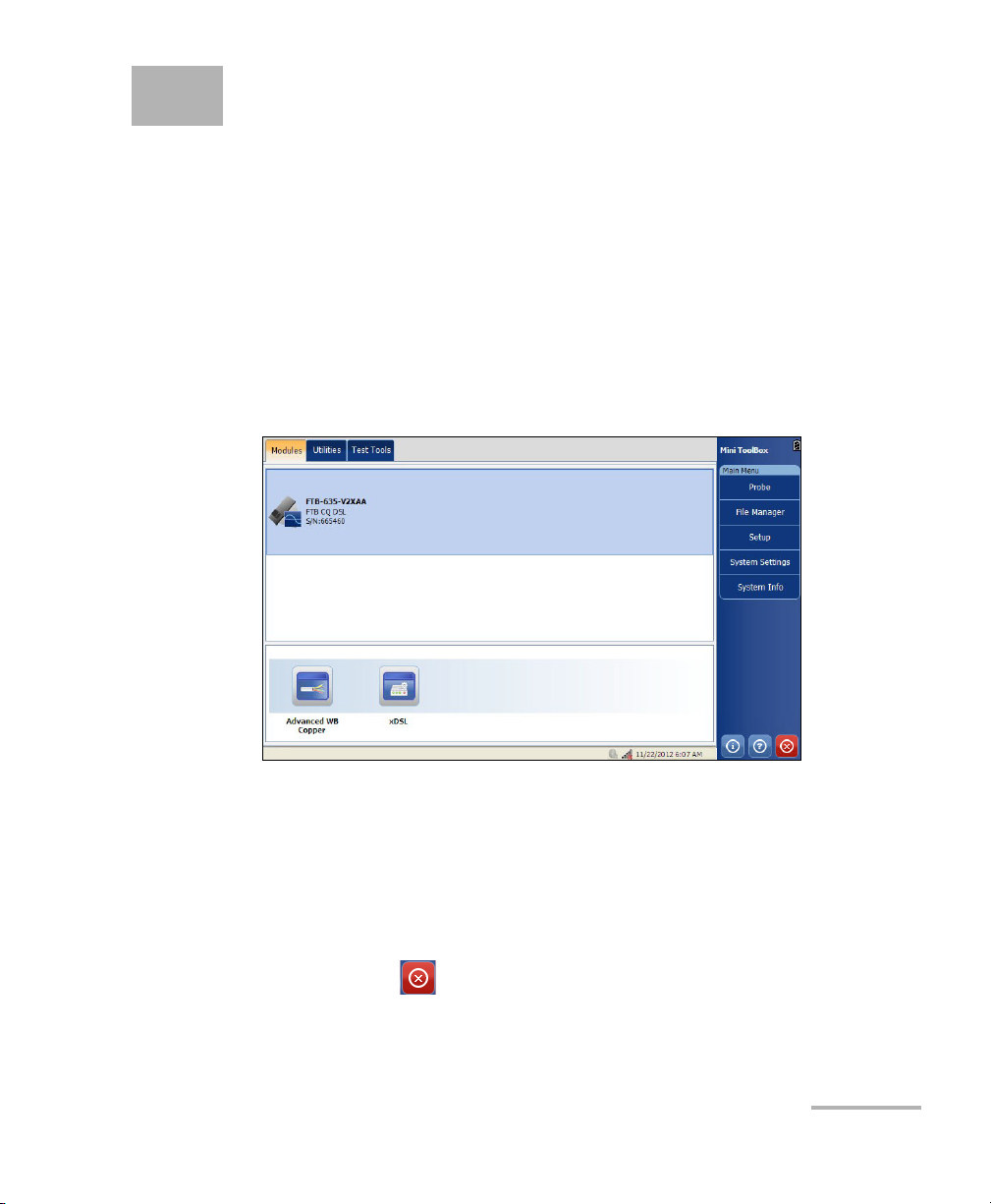
Getting Started
Primary tip/ring
(A/B) connectors
Ground (Earth)
terminal
Secondary tip/ring (A/B)
connectors
Headset
POTS Speaker
Ethernet LAN and DSL Ports
Cable Connections
Cable Connections
These connections are intended for the express purpose of electrical
testing of common telephone line conductors, within the ranges
specified in the Technical Specifications on page 353. The device is
not intended to be used on telephone lines having voltages greater
than 280 VAC or 400 VDC, and it is also not intended to be used on
power distribution circuits.
The graphics below show the connectors on the FTB-635 device.
WARNING
Note: When connecting a network cable to the LAN port, use the RJ-45 plug end
of the cable provided with the unit. There is a 1500 V maximum transient
voltage on telecom ports. Basic insulation is needed for external telecom
circuits.
10 FTB-635
Page 19
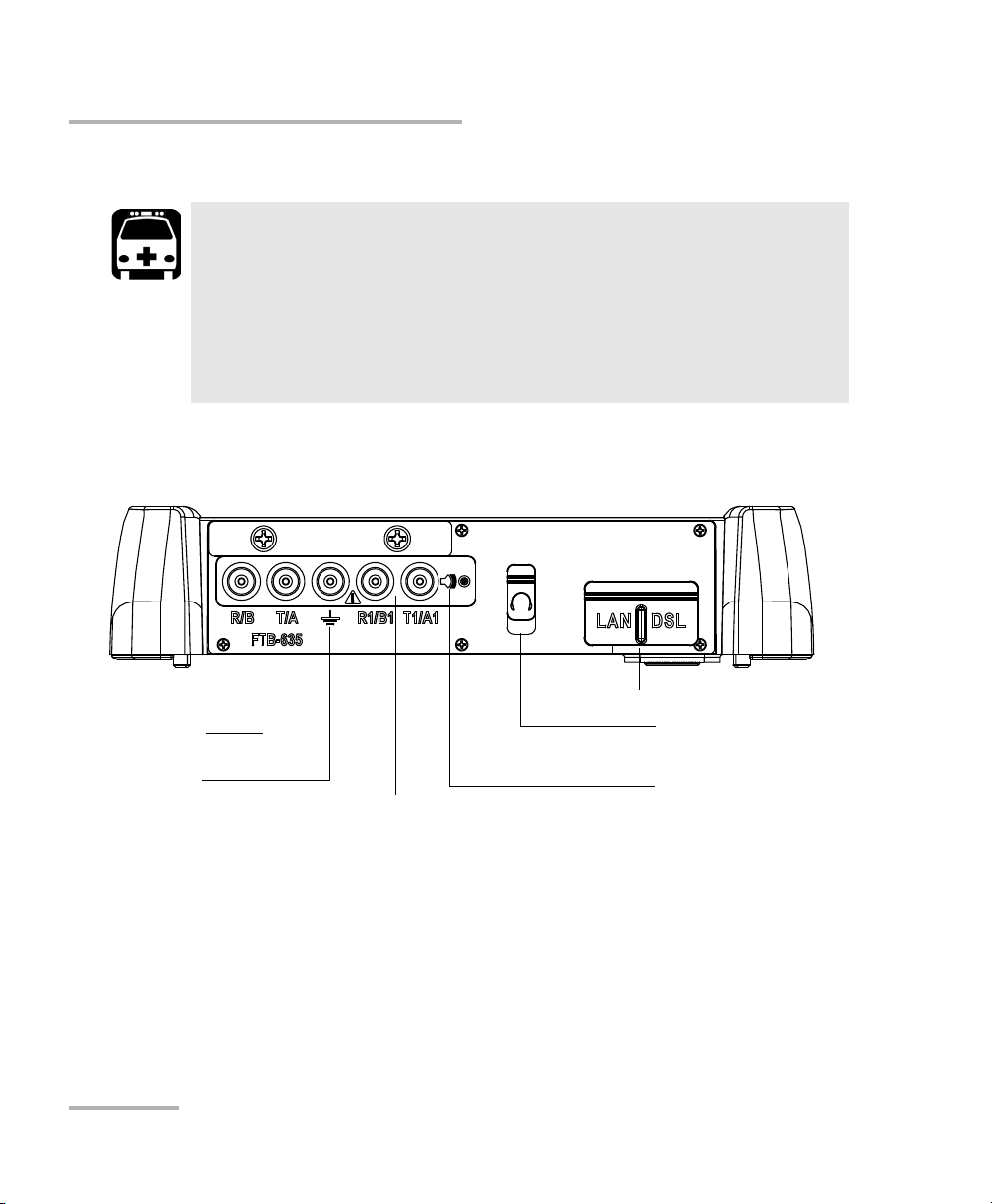
Getting Started
Shield of phone
line
Secondary Ring/B
wire of phone
line
Secondary Tip/A
wire of phone
line
Primary Ring/B wire of phone line
Primary Tip/A wire of phone line
Cable Connections
WARNING
A 50/100/125/500 Vcc limited power source may be present on connector R/T/R1/T1 when the unit is testing isolation resistance. Use
with caution.
The unit is protected against damage caused by fault voltages that
may be present on lines under test. Do not connect the unit if the
maximum expected fault voltage is greater than 500 volts.
Copper and xDSL Tests 11
CAUTION
Page 20

Getting Started
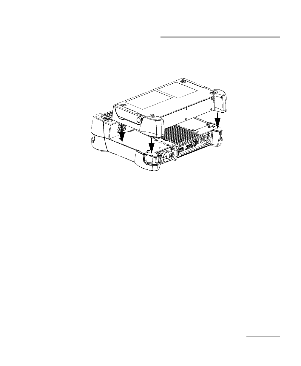
Inserting and Removing Test Modules
Inserting and Removing Test Modules
Never insert or remove a module while the FTB-1 is turned on. This
will result in immediate and irreparable damage to both the
module and unit.
To avoid damaging your unit, use it only with modules approved by
EXFO.
To insert a module into the FTB-1:
1. Turn off your unit (shutdown, not hibernate or standby).
2. Position the unit so that its front panel rests on a flat surface such as a
table.
CAUTION
CAUTION
12 FTB-635
Page 21
Getting Started
Inserting and Removing Test Modules
Place the module on the platform making sure that the bumpers and the
shorter sides of the module are flush with those of the platform. If
necessary, slightly move the module until alignment is correct.
Copper and xDSL Tests 13
Page 22
Getting Started
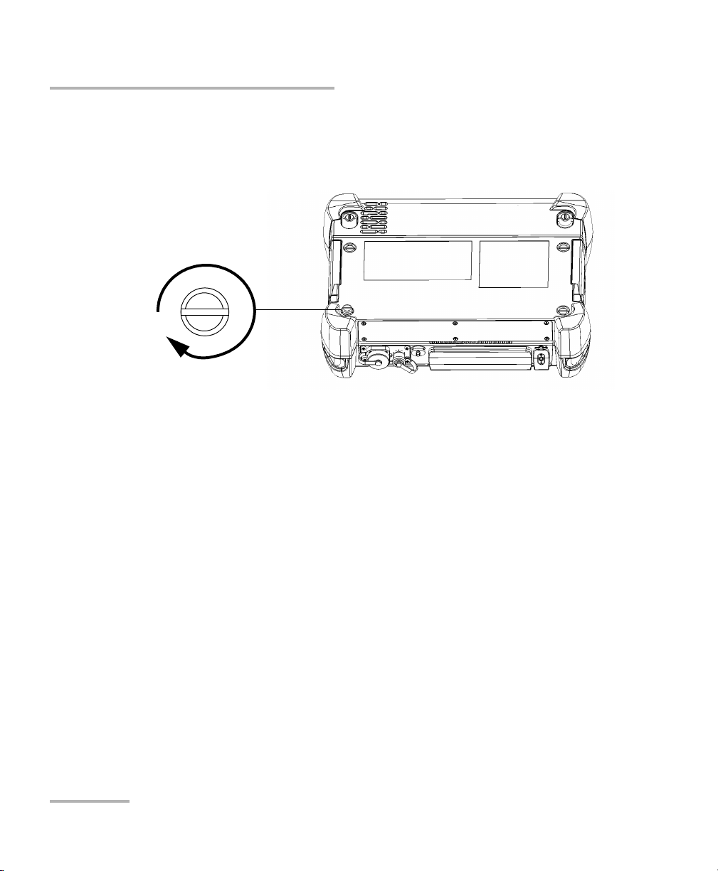
Turn screws
clockwise
Back panel
Inserting and Removing Test Modules
3. Using a flat screwdriver, turn the screws (4) clockwise until they are
tightened.
This will secure the module into its “seated” position.
When you turn on the unit, the startup sequence will automatically detect
the module.
14 FTB-635
Page 23
Getting Started
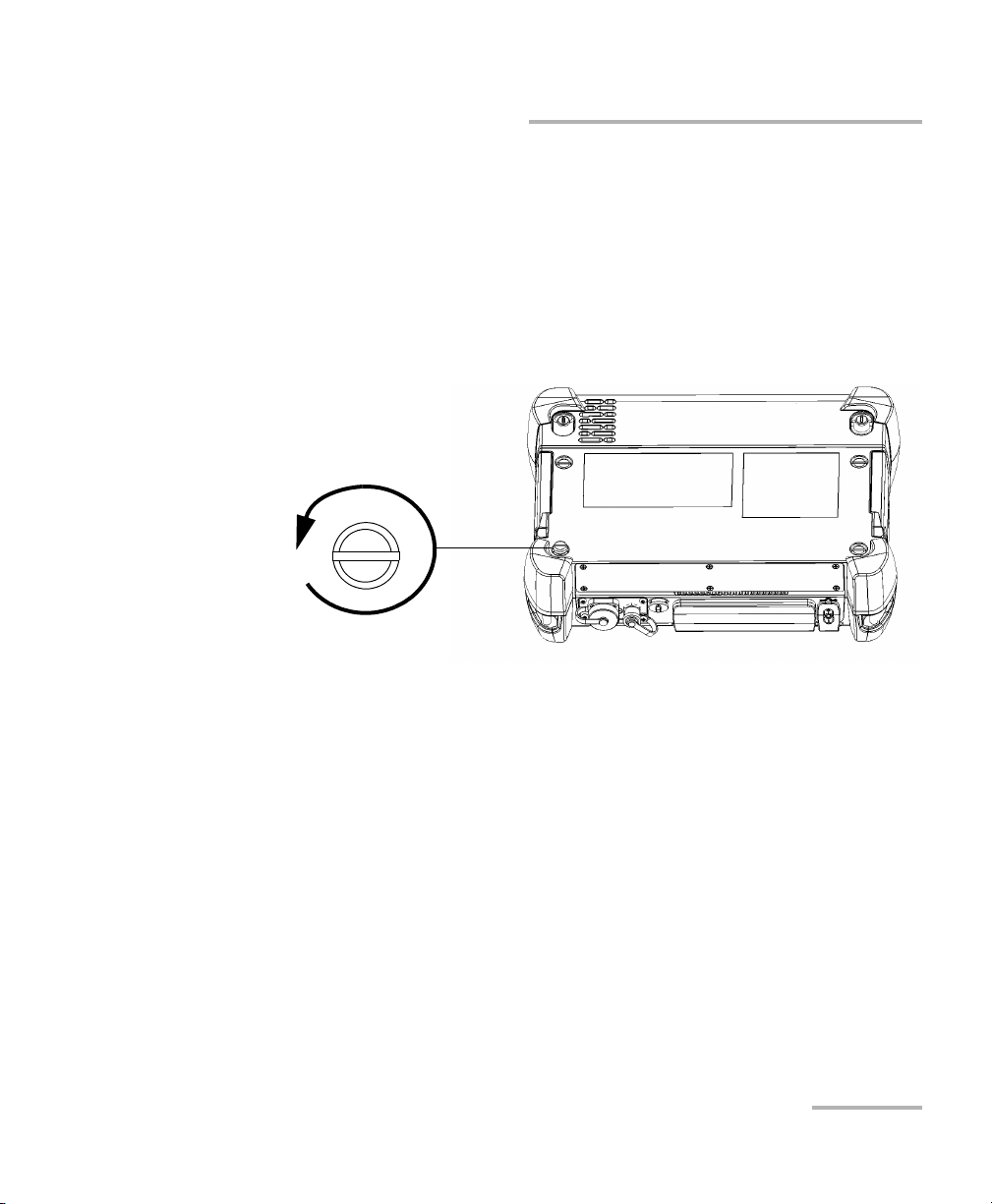
Turn screws
counterclockwise
Back panel
Inserting and Removing Test Modules
To remove a module from the FTB-1:
1. Turn off your unit (Shutdown).
2. Position the unit so that its front panel rests on a flat surface such as a
table.
3. Using a flat screwdriver, turn the screws (4) counterclockwise until
they are loose. Since they are captive screws, you cannot remove them
completely.
Copper and xDSL Tests 15
Page 24
Getting Started
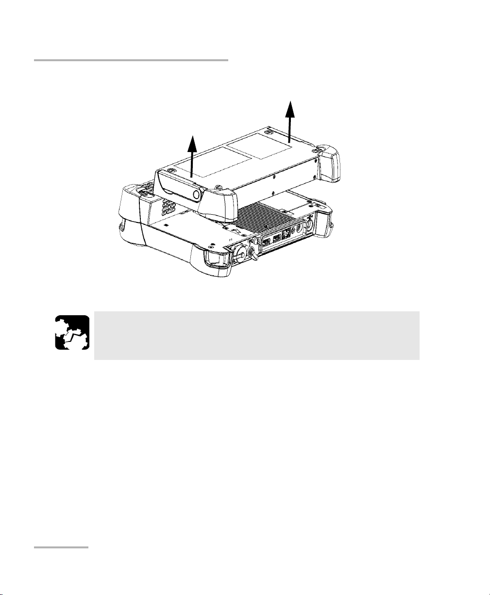
Inserting and Removing Test Modules
4. Hold the module by its sides (NOT by the connectors) and pull it up.
CAUTION
Pulling a module by its connectors could seriously damage both the
module and connector. Always pull a module by its casing.
16 FTB-635
Page 25

Getting Started
Performing FTB-1 Software Updates
Performing FTB-1 Software Updates
The FTB-1 software updates can only be performed by a Supervisor, since
only Supervisors are given administrative rights (upon FTB-1 login). Since
administrative rights are required in order to use Update Manager, persons
logging in as an Operator will not have access to Update Manager.
After completing the FTB-1 software update using Update Manager, the
Supervisor should always run the newly installed application. The reason
for this is that some updates may require a module firmware update, and
only a Supervisor has the administrative rights to allow this update to
proceed. If a module firmware update is required, but is not performed by
the Supervisor (that is, by running the application), then when an Operator
attempts to start the application the following message is displayed:
Module firmware update required. Please login as Administrator.
The above message may also be displayed if an Operator replaces the
FTB-1 module with a module from another FTB-1 that does not have the
required module firmware. For both cases the Operator will only have
access to the application if a Supervisor logs into the FTB-1 and completes
the installation of the module firmware.
Copper and xDSL Tests 17
Page 26
Getting Started
Performing FTB-1 Software Updates
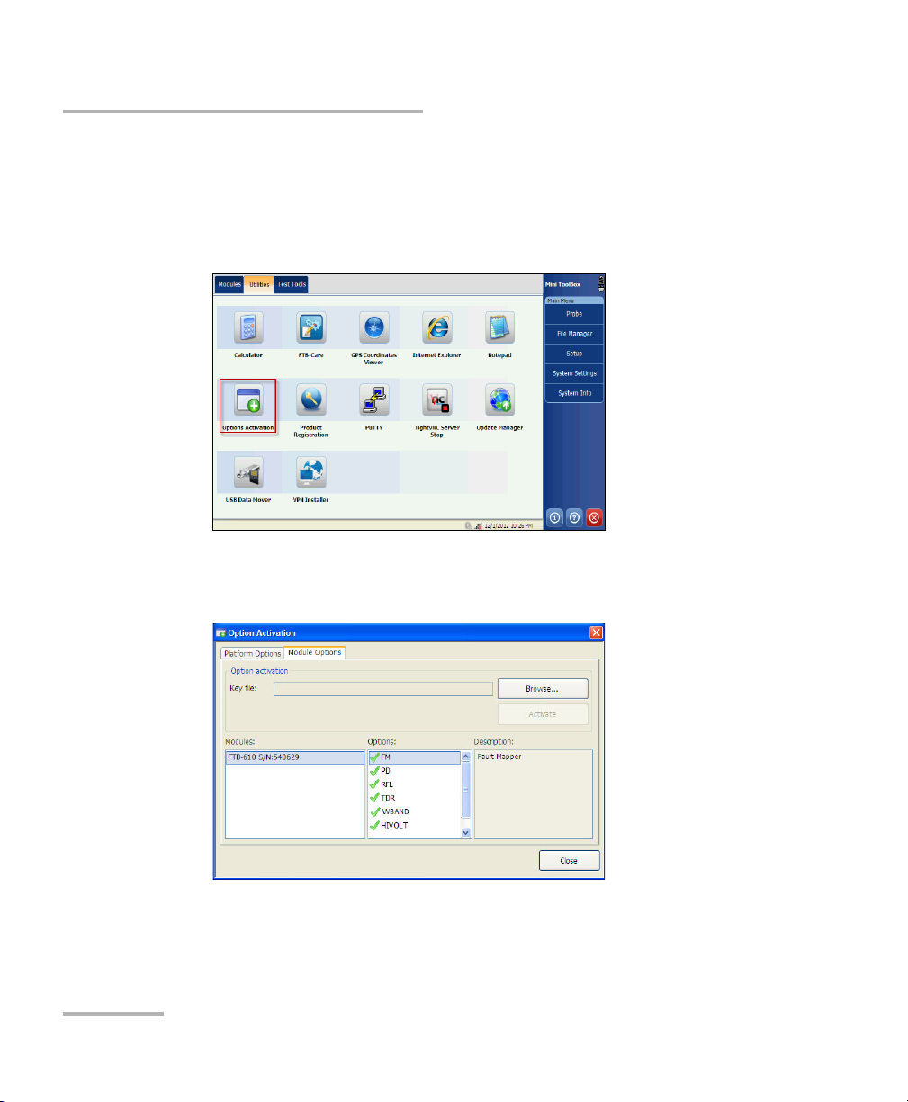
To view the software options enabled on your FTB-635 Wideband
Copper and DSL Test Module:
1. From the Mini ToolBox, select the Utilities tab, then tap Options
Activation.
2. Select the Module Options tab.
You can see the supported options for the module in the Options list.
18 FTB-635
Page 27
Getting Started
Usual Tab Elements
Usual Tab Elements
While configuring tests or consulting results, different tabs and buttons
allow you to navigate within the application.
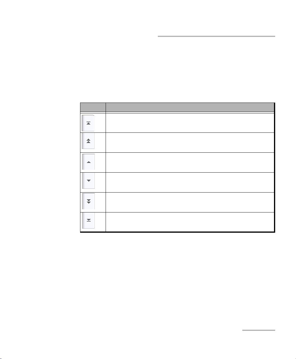
Arrow Buttons
Button Description
Moves to the top of the list.
Moves one page up.
Moves one line up.
Moves one line down.
Moves one page down.
Moves to the end of the list.
Copper and xDSL Tests 19
Page 28
Getting Started
Usual Tab Elements
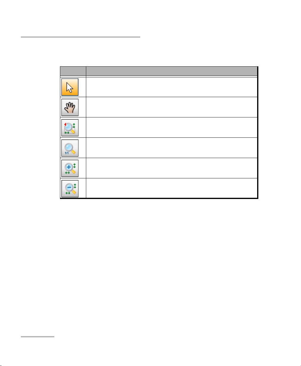
Graph Controls
Button Description
Arrow enables cursor mode (move a vertical cursor to get
precise information about the plot along the x-axis).
Hand is used to pan around the graph.
Used to draw a zoom box to select an area on the graph.
Resets the graph to original size (full view).
Zoom in.
Zoom out.
20 FTB-635
Page 29
4 Advanced WB Copper
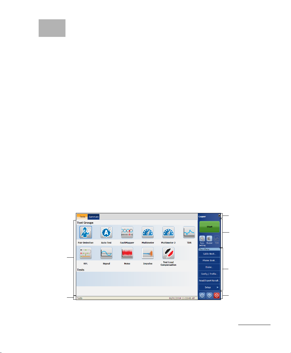
Title Bar
Main Menu
Main
Window
Status Bar
Application
Button
Te st
Information
and Control
Application
Using the Graphical User Interface
This chapter describes the graphical user interface of the Copper tests
application.
The graphical user interface allows you to configure and start the Copper
tests, view results and statistics, and other information related to the
FTB-635. The application user interface contains:
Main Window
Status Bar
Title Bar
Test M e nu
Application Buttons
Main Window
The main window allows you to view the first and second level tabs for test
groups, the tests within groups, and results as applicable.
Copper and xDSL Tests 21
Page 30

Advanced WB Copper Application
Navigation Path
Test Status
Date and Time
Status Bar
Test Grou ps
The Copper application provides you the following Te st Gr o ups:
Pair Detective
Auto Test
FaultMapper
Multimeter
Multimeter 2
TDR
RFL
Signal
Noise
Impulse
Test Lead Compensation
Tests
The Test s section of the main window displays the selected test or its
sub-tests.
Status Bar
The Status Bar displays the navigation path of the test, date, and time.
22 FTB-635
Page 31

Advanced WB Copper Application
Title Bar
The Title Bar displays the software application name and the battery level
indicator.
Test Information and Control
Yo ur Copper application allows you to view the global indicator, Start/Stop
any test or tool, use control buttons, and use the main menu to setup
tests/tools and view test results.
Start/Stop button: for more details, see Start/Stop Button on page 27.
Application Settings: for more details, see Application Settings on
page 66.
The Buzzer icon is a shortcut for Buzzer tab under Application
settings. For more details, see Buzzer on page 72.
The TDR icon is a shortcut for the TDR test which is activated for
Load Coils, Pair Detective and FaultMapper tests. For more details, see
TDR Test on page 187.
Title Bar
Main Menu
The Main Menu displays the Setup and Result button. Setup allows you to
configure a test or tool, and the Result button allows you to view respective
test results.
Copper and xDSL Tests 23
Page 32

Advanced WB Copper Application
Application buttons
Application buttons
Help Button
The help button displays the help information related to the tab. It is
also possible to navigate through the remainder of the help information.
About Button
You can view the product version details and technical support information
in this window.
To view the information about the product:
1. From the main window, tap .
24 FTB-635
Page 33

Advanced WB Copper Application
Application buttons
2. Ta p Information to view further details about the product, software,
and memory installed on the device.
2a. You can view the complete versioning information by
double-tapping on the Version value.
2b. Double-tap the Version value again to return to the original value.
Copper and xDSL Tests 25
Page 34

Advanced WB Copper Application
Application buttons
3. Ta p View License Agreement to view further details about using the
product and software.
Exit Button
The Exit button closes the application.
26 FTB-635
Page 35

5 Copper Tests: Using the Main
Menu
The FTB-635 is designed to test twisted pair quality, identify and locate
faults, and troubleshoot noise and signal issues. These measurements offer
a quick and thorough method to determine if the cable is capable of
supporting xDSL technology.
Start/Stop Button
The Start/Stop button allows you to start and stop a test. The button text
changes depending on the action performed (toggle button).
Start: when the test is not running.
Stop: when the test is running.
Copper and xDSL Tests 27
Page 36

Copper Tests: Using the Main Menu
Cable Book
Cable Book
The Cable Book menu presents a selection of functions which allow you to
manage the groups of cables relevant to performing the copper tests. The
Cable Book menu allows you to load, add, clone, and delete a cable, as
well as modify its details.
To access Cable Book:
From the Copper Main Menu, select Cable Book
.
28 FTB-635
Page 37

Copper Tests: Using the Main Menu
Cable Book
Load Cable
The page lists entries by Cable ID and Cable Name. There is 1 group of 10
factory default entries which cannot be edited or deleted. The Cable Book
can include a maximum of 50 groups.
To load a cable:
1. From the Main Menu, tap Cable Book.
2. From the Cable Management tab, select the cable that you want to
load.
3. Ta p Load Cable button to load the group/entry.
Copper and xDSL Tests 29
Page 38

Copper Tests: Using the Main Menu
Cable Book
Cable Details
The Cable Details page allows you to view the cable parameter details of
the currently highlighted cable entry.
To view/modify cable details:
1. From the Main Menu, tap Cable Book.
2. From the Cable Management tab, select the cable for which you want
to view details.
3. Select the Cable Details tab to view the details.
4. Ta p Close to exit from the page.
The page displays the following parameters:
Cable ID displays the cable ID number.
Cable Name is the name of the cable in the Cable Book.
Cable Gauge is the gauge system for measuring wire sizes in AWG
(American Wire Gauge) units or mm (metric wire size).
Cable Fill Material is the type of material the cable is filled with:
Aircore, Jelly, Pulp, 5 PR, or 2 PR. The selection influences the cable
capacitance per length, automatically updating the Cap. T/R to GND
field.
30 FTB-635
Page 39

Copper Tests: Using the Main Menu
Cable Book
Capacitance T-R specifies a value for the capacitance per length
constant.
Capacitance T/R to GND specifies a value for the capacitance per
length to ground constant.
Resistance specifies a value for the resistance constant of the cable.
Attenuation @ 300 kHz specifies a value for the reduction in signal
strength or insertion loss of the cable.
Velocity of propagation for the cable as a ratio of the speed of light.
Tem pe ra tu re specifies the temperature of reference at which all cable
parameters have been measured, in either F (Fahrenheit) or C
(Celsius) units. The measurement units are updated based on the
Tem pe ra tu re settings in the Application Settings, General on page 66.
Copper and xDSL Tests 31
Page 40

Copper Tests: Using the Main Menu
Cable Book
Add Cable
The Add Cable page allows you to add a new cable entry into the Cable
Book using the following parameters for the currently highlighted Cable
ID.
To add a Cable:
1. From the Main Menu, tap Cable Book.
2. Select the Cable Management tab and tap Add Cable.
The Add Cable dialog opens.
The page allows you to set the following parameters:
Cable ID displays the cable ID number. This parameter cannot be
modified.
Cable Name is displayed in the Cable Book.
Cable Gauge allows you to enter the Cable Gauge. This is the gauge
system for measuring wire sizes in AWG (American Wire Gauge) units
or mm (metric wire size).
32 FTB-635
Page 41

Copper Tests: Using the Main Menu
Cable Book
Cable Fill Material allows you to select the type of material the cable
can be filled with. Changing the selection to Aircore, Jelly, Pulp 5 PR,
or 2 PR influences the cable capacitance per length, automatically
updates the Capacitance T/R to GND field.
Capacitance T-R allows you to specify a value for the capacitance per
length constant.
Capacitance T/R to GND allows you to specify a value for the
capacitance per length to ground constant.
Resistance allows you specify a value for the resistance constant of the
cable.
Attenuation @ 300 kHz allows you to specify a value for the reduction
in signal strength or insertion loss of the cable.
Velocity of propagation allows you to set the velocity of propagation
for the cable as a ratio of the speed of light.
Temperature allows you to specify the temperature of reference at
which all cable parameters have been measured.
Add button, tap the Add button to append the new cable entry to the
end of the Cable Book. If the maximum number of Cable Book entries
has been reached, delete an entry before adding a new one.
Copper and xDSL Tests 33
Page 42

Copper Tests: Using the Main Menu
Cable Book
Clone Cable
The Clone Cable option allows you to copy the cable details of an existing
entry to a new cable entry in the Cable Book.
To clone a cable entry:
1. From the Main Menu, tap Cable Book.
2. From the Cable Management tab, select the cable ID that you want to
clone.
3. Ta p the Clone Cable button to copy the details of the highlighted entry
and append a new Cable ID to the list.
34 FTB-635
Page 43

Copper Tests: Using the Main Menu
Delete Cable
The Delete Cable page allows you to delete a cable entry from the Cable
Book. The page lists all entries, excluding the 10 factory default cable
entries, by Cable ID and Cable Name.
To delete a cable entry:
1. From the Main Menu, tap Cable Book.
2. Select the Cable Management tab and tap Delete Cable.
The Delete Cable dialog opens.
3. Select the cable ID that you want to delete.
Note: Check the Select All Cables to specify all cable IDs.
4. Ta p the Delete Cable button to remove the entry from the Cable Book.
If you try to delete a cable in use, a warning message pops-up.
Cable Book
Copper and xDSL Tests 35
Page 44

Copper Tests: Using the Main Menu
Phone Book
Phone Book
The Phone Book menu presents a selection of functions which allow you
to manage the groups of phone numbers relevant to performing the copper
tests. It can include a maximum of 50 groups of up to 3 individual entries
each.
To access Phone Book:
From the Copper Main Menu, select Phone Book
.
36 FTB-635
Page 45

Copper Tests: Using the Main Menu
Phone Book
Load Group/Entry
The page lists entries by Group ID and Entry Name/Type. There is 1 group
of 3 factory default entries which cannot be edited or deleted. The Phone
Book can include a maximum of 50 groups.
To load Group/Entry:
1. From the Main Menu, tap Phone Book.
2. From the Phone Book Management tab, select the group which you
want to load.
3. Ta p the Load Group/Entry button to load the group/entry.
Copper and xDSL Tests 37
Page 46

Copper Tests: Using the Main Menu
Phone Book
Phone Book Details
The Phone Book Details page allows you to view and modify the Phone
Book parameters of the currently highlighted phone entry. As well, you can
enable/disable entries 2 and 3 in each phone group. When creating a new
phone group, only entry 1 is enabled. Entries 2 and 3 remain disabled until
entry 1 is filled in.
To view/modify Phone Book details:
1. From the Main Menu, tap Phone Book.
2. From the Phone Book Management tab, select the group which you
want to load.
3. Select the Phone Book Details tab to view the details.
4. Ta p Close to exit from the page.
38 FTB-635
Page 47

Copper Tests: Using the Main Menu
Phone Book
The page displays the following parameters:
Group ID displays the group ID number. This is the only parameter that
cannot be modified however you can navigate between the available
phone groups.
Entry Name is the name of the entry in the Phone Book.
Phone Number is the 10-digit numeric phone number of the entry.
Typ e displays the following list of values:
Milliwatt tone
Drop battery
Quiet line
- (for additional line types)
Accept button validates and updates all the parameters of the Phone
Book.
Copper and xDSL Tests 39
Page 48

Copper Tests: Using the Main Menu
Phone Book
Add Group
The Add Group page allows you to add a new group entry into the Phone
Book using the following parameters for the currently highlighted Group
ID.
To Add Group:
1. From the Main Menu, tap Phone Book.
2. From the Phone Book Management tab, tap Add Group.
The page displays the following parameters:
Group ID displays the group ID number. This parameter that cannot be
modified.
Entry Name is the name of the entry in the Phone Book.
Phone Number is the 10-digit numeric phone number of the entry.
40 FTB-635
Page 49

Copper Tests: Using the Main Menu
Phone Book
Typ e displays the following list of values:
Milliwatt tone
Drop battery
Quiet line
- (for additional line types)
Add function key adds the new group entry to the Phone Book.
Clone Group
The Clone Group page allows you to copy the details of an existing entry to
a new group entry in the Phone Book. The page lists all entries by Group
ID.
The list can display a maximum of 50 entries.
To Clone Group:
1. From the Main Menu, tap Phone Book.
2. From the Phone Book Management tab, select the group you want to
clone.
3. Ta p Clone Group.
Copper and xDSL Tests 41
Page 50

Copper Tests: Using the Main Menu
Phone Book
Delete Group
The Delete Group page allows you to delete a group entry from the Phone
Book. The page lists all entries by Group ID.
To delete a group entry:
1. From the Main Menu, tap Phone Book.
2. From the Phone Book Management tab, select the group you want to
delete.
Note: Select the Select All Groups option to select all group IDs.
3. Ta p the Delete Group button to remove the entry from the Cable
Book. If you try to delete a group in use, a warning message pops-up.
42 FTB-635
Page 51

Copper Tests: Using the Main Menu
Phone Book
Load Phone Book
The Load Phone Book page allows you to import a phone book. The page
displays the file name and date of the last phone book loaded. Only .csv
files are supported.
To load Phone Book:
1. From the Main Menu, tap Phone Book.
2. Ta p the Load Phone Book button.
The Load Phone Book dialog opens.
3. Select the file name to load.
4. Ta p Load and confirm. The unit will remove the existing phone book
and replace it by the loaded one.
OR
5. Ta p Cancel to remove the message.
Copper and xDSL Tests 43
Page 52

Copper Tests: Using the Main Menu
Phone Book
The page displays the following parameters:
The File Storage Location lists the load destinations:
FTB-1 internal memory
Name of the USB Device (if attached)
File Name lists the phone book file name(s) to load.
Load button imports the selected phone book. You will be prompted
for confirmation since this action will overwrite the current phone
book.
Cancel button removes the confirmation/warning message without
impacting the phone book.
Save Phone Book
The Save Phone Book page allows you to save or export a phone book.
To Save Phone Book:
1. From the Main Menu, tap Phone Book.
2. From the Phone Book Management tab, tap the Save Phone Book
button.
The Save Phone Book dialog opens.
44 FTB-635
Page 53

Copper Tests: Using the Main Menu
Phone Book
The page displays the following parameters:
Enter File Name allows you to enter a file name of the current phone
book to save. By default, the name is phone_book.
Select File Storage Location lists the save destinations:
FTB-1 internal memory
Name of the USB Device (if attached)
Save button saves the selected file. Only .csv files are supported.
Note: The platform will overwrite any document with the same file name found
on the disk, without warning.
Copper and xDSL Tests 45
Page 54

Copper Tests: Using the Main Menu
Dialer
Dialer
The Dialer function provides a dial-up path from the module to another
tester (or quiet termination or silent switchman) through a switched circuit
network. DTMF transmission is enabled via the phone keypad allowing you
to place POTS calls. The dialer can be accessed from the Copper Main
Menu and is also integrated into individual test screens to give you quick
access to the manual dialer function, speed dial and last dialed lists,
without exiting the current test application.
The Dialer function allows you to use the unit as a telephone (with a
headset) and the on-screen phone keypad as a dialer when Enter Number
is invoked, whether in the test results screens or through the separate
dedicated Dialer application. An external speaker on top of the module
provides DTMF audio, while a headset jack also lets you connect a headset
and microphone.
To access the Dialer function:
From the Main Menu select Dialer.
46 FTB-635
Page 55

Copper Tests: Using the Main Menu
Dialer
The following functions can be accessed from this page:
Dialing Status shows the current status of the dialed number.
Enter Number displays the telephone number entered or selected
from the Recent Dialed Numbers list or Phone Book.
Recent button opens a list of recently dialed numbers for selection.
Select button allows you to select a number from the Phone Book.
Function Keys
Dial/Hang Up allows you to dial the selected or entered number,
or hang up the dialer.
Add saves the entered number to the Phone Book.
Mute Speaker changes the speaker status.
Volu me adjusts the volume level.
To dial a number:
1. Enter a new phone number using the on-screen or hard keypad, or
select an existing one from the phone book or recent dialed list.
2. Ta p the Dial button to start the call.
Enter Number
The Enter Number box is where you enter the phone number you wish to
dial.
To enter a phone number:
1. Enter the phone number.
2. Delete a character by moving the cursor to the left of the character and
tapping the Del button.
3. Ta p Dial button when you have completed entering a phone number.
Note: Alphabets on the key pad are for reference only. Tapping any of the buttons
will not show the alpha-character in the text box.
Copper and xDSL Tests 47
Page 56

Copper Tests: Using the Main Menu
Dialer
Recent Dialed Numbers
The Recent Dialed Numbers page lists a maximum of 25 recently dialed
telephone numbers which you can select to make your call.
To select a recently dialed number:
1. Ta p Recent button to open the Recent Dialed Numbers page.
2. Select the number.
3. Tap the OK button. The number is automatically entered in the Enter
Number field of the Dialer page.
Select from Phone Book
The Select Phone Book Entry page lists entries by Group ID and Entry
Name/Type. There is 1 group of 3 factory default entries which cannot be
edited or deleted. The Phone Book can include a maximum of 50 groups.
Group # in Use displays the group number in use.
To select a group and entry:
1. Ta p Select button to open the Select Phone Book Entry page.
2. Select the desired entry and tap OK. The Group # in Use is updated
with the current selection and automatically entered in the Enter
Number field of the Dialer page.
48 FTB-635
Page 57

Copper Tests: Using the Main Menu
Dialer
Add to Phone Book
The Add Phone Group page allows you to add a new group entry into the
Phone Book using the following parameters for the currently highlighted
Group ID.
Group ID displays the group ID number. This parameter that cannot be
modified.
Entry Name is the name of the entry in the Phone Book.
Phone Number is the 10-digit numeric phone number of the entry.
Typ e displays the following list of values:
Milliwatt tone
Drop battery
Quiet line
- (for additional line types)
Add button adds the new group entry to the Phone Book.
To add a number to the phone book:
1. Tap Add on the Dialer page.
2. Enter the required details.
3. Ta p the Add button to append the new group entry to the end of the
Phone Book. If the maximum number of Phone Book entries has
been reached, delete an entry before adding a new one.
Copper and xDSL Tests 49
Page 58

Copper Tests: Using the Main Menu
Config/Profile
Config/Profile
The Config/Profile menu presents a selection of functions, which allows
you to manage the profiles and view the profile details. The FTB-635
Wideband Copper and DSL Test Module supports several types of copper
test applications. Configuration parameters are saved into a test
configuration profile. A Profile Default is provided with a predefined set of
parameters for all test applications.
To access Config/Profile:
From the Copper Main Menu, select Config/Profile
.
50 FTB-635
Page 59

Copper Tests: Using the Main Menu
Config/Profile
Load
The Profile Management page lists the available profiles in the internal
memory, by Profile Name and Modification Date.
To load Profile:
1. From the Main Menu, tap Config/Profile.
2. From the Profile Management tab, select the profile which you want
to load.
3. Ta p the Load button to load the Profile.
Copper and xDSL Tests 51
Page 60
Copper Tests: Using the Main Menu
Config/Profile
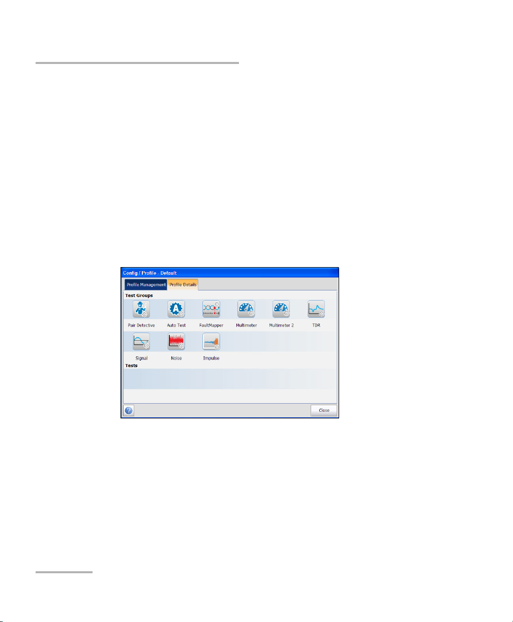
Profile Details
You can view any of your saved profiles on the FTB-635 Wideband Copper
and DSL Test Module from the Profile Details menu by selecting the
desired test icon. An asterisk “*” on the currently Selected Profile name
indicates that modifications have been made to this profile in the threshold
settings or parameters of a particular test.
Each test displays a sub-menu of test icons to select and setup.
To view Profile details:
1. From the Main Menu, tap Config/Profile.
2. From the Profile Details tab, select the test for which you want to view
the details.
52 FTB-635
Page 61

Copper Tests: Using the Main Menu
The page displays the following tests:
Pair Detective
Auto Test
FaultMapper
Multimeter
Multimeter 2
TDR
Signal
Noise
Impulse
Config/Profile
Copper and xDSL Tests 53
Page 62

Copper Tests: Using the Main Menu
Config/Profile
Pair Detective Profile Details
The profile details Pair Detective main menu allows you to view the test
threshold and parameters.
To view the Pair Detective Profile details:
1. From the Main Menu, tap Config/Profile.
2. Ta p the Profile Details tab.
3. From the Te s t G roup s , select the Pair Detective test.
4. From the Te sts menu, select the test for which you want to view the
details.
54 FTB-635
Page 63

Copper Tests: Using the Main Menu
Config/Profile
Auto Test Profile Details
The profile details Auto Test main menu allows you to view the test
threshold and parameters of the following tests:
Pots Auto Test
User Auto Test
To view the Auto Test Profile details:
1. From the Main Menu, tap Config/Profile.
2. Ta p the Profile Details tab.
3. From the Te s t G roup s , select the Auto test.
4. From the Te sts menu, select the test for which you want to view the
details.
Copper and xDSL Tests 55
Page 64

Copper Tests: Using the Main Menu
Config/Profile
FaultMapper Test Profile Details
The profile details FaultMapper Test main menu allows you to view the
test threshold and parameters.
To view the FaultMapper Test Profile details:
1. From the Main Menu, tap Config/Profile.
2. Ta p the Profile Details tab.
3. From the Te s t G roup s , select the FaultMapper test.
4. From the Te sts menu, select the test for which you want to view the
details.
56 FTB-635
Page 65

Copper Tests: Using the Main Menu
Config/Profile
Multimeter Test Profile Details
The profile details Multimeter main menu allows you to view the test
threshold and parameters of the following tests:
Voltage
Current
Resistance
Capacitance/Opens
Resistive Balance
Balance
To view the Multimeter Test Profile details:
1. From the Main Menu, tap Config/Profile.
2. Ta p the Profile Details tab.
3. From the Te s t G roup s , select the Multimeter test.
4. From the Te sts menu, select the test for which you want to view the
details.
Copper and xDSL Tests 57
Page 66

Copper Tests: Using the Main Menu
Config/Profile
Multimeter 2 Test Profile Details
The profile details Multimeter 2 main menu allows you to view the test
threshold and parameters of the following tests:
Isolation
Station Ground
To view the Multimeter 2 Test Profile details:
1. From the Main Menu, tap Config/Profile.
2. Ta p the Profile Details tab.
3. From the Te s t G roup s , select the Multimeter 2 test.
4. From the Te sts menu, select the test for which you want to view the
details.
58 FTB-635
Page 67

Copper Tests: Using the Main Menu
Config/Profile
TDR Test Profile Details
The profile details TDR main menu allows you to view the test threshold
and parameters of the following tests:
Auto TDR
Manual TDR
Xtalk TDR
To view the TDR Test Profile details:
1. From the Main Menu, tap Config/Profile.
2. Ta p the Profile Details tab.
3. From the Te s t G roup s , select the TDR test.
4. From the Te sts menu, select the test for which you want to view the
details.
Copper and xDSL Tests 59
Page 68

Copper Tests: Using the Main Menu
Config/Profile
Signal Test Profile Details
The profile details Signal main menu allows you to view the test threshold
and parameters of the following tests:
WB Balance
WB Attenuation
TX/RX Tone
To view the Signal Test Profile details:
1. From the Main Menu, tap Config/Profile.
2. Ta p the Profile Details tab.
3. From the Te s t G roup s , select the Signal test.
4. From the Te sts menu, select the test for which you want to view the
details.
60 FTB-635
Page 69
Copper Tests: Using the Main Menu
Config/Profile
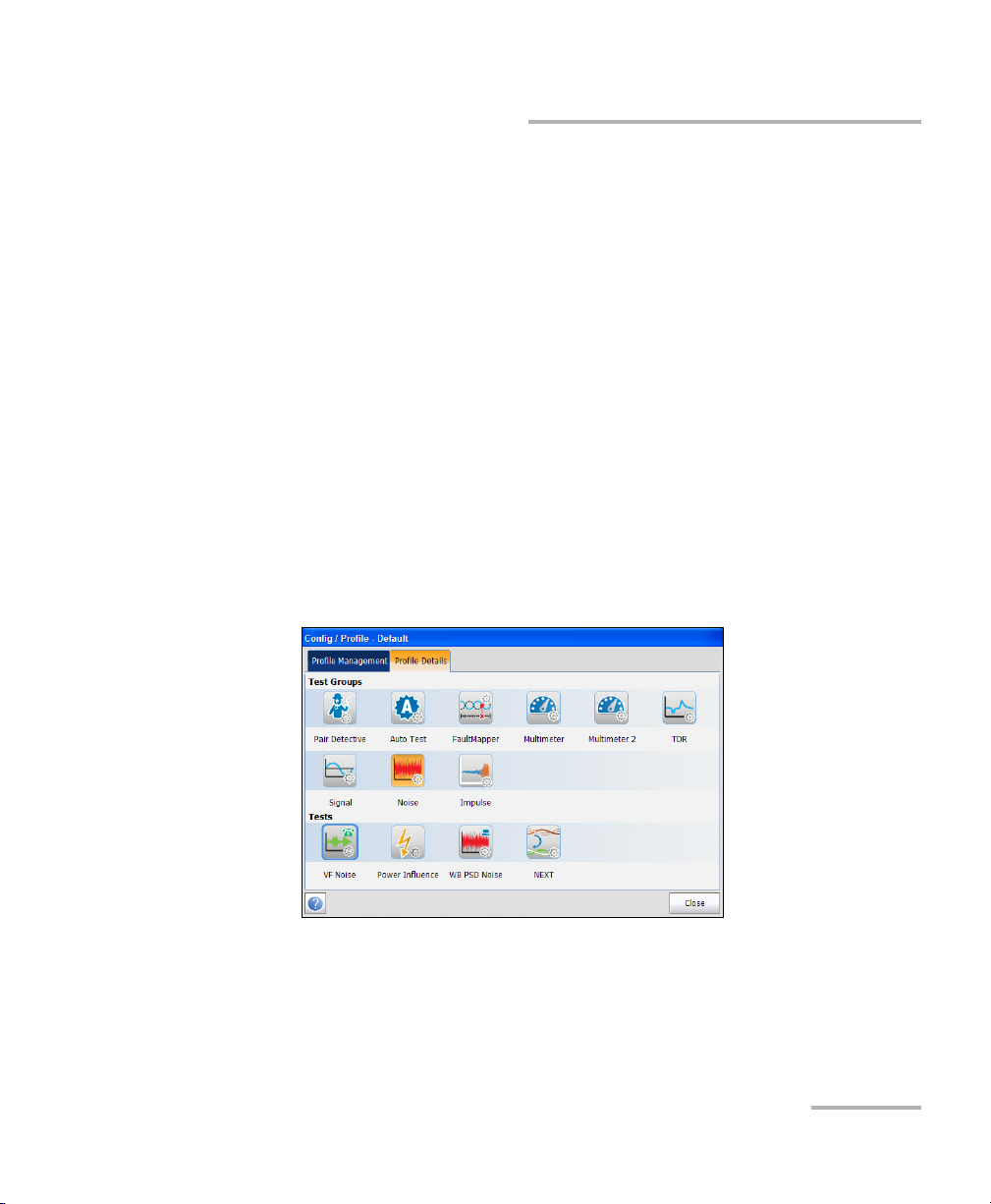
Noise Test Profile Details
The profile details Noise main menu allows you to view the test threshold
and parameters of the following tests:
VF Noise
Power Influence
WB PSD Noise
NEXT
To view the Noise Test Profile details:
1. From the Main Menu, tap Config/Profile.
2. Ta p the Profile Details tab.
3. From the Te s t G roup s , select the Noise test.
4. From the Te sts menu, select the test for which you want to view the
details.
Copper and xDSL Tests 61
Page 70

Copper Tests: Using the Main Menu
Config/Profile
Impulse Test Profile Details
The profile details Impulse main menu allows you to view the test
threshold and parameters of the following tests:
VF Impulse Noise
WB Impulse Noise
Impulse Scope
Impulse Duration
To view the Impulse Test Profile details:
1. From the Main Menu, tap Config/Profile.
2. Ta p the Profile Details tab.
3. From the Te s t G roup s , select the Impulse test.
4. From the Te sts menu, select the test for which you want to view the
details.
62 FTB-635
Page 71

Copper Tests: Using the Main Menu
Copy from USB
Copy from USB allows you to copy all profiles found on an external USB
device to the unit.
To copy the profile details:
1. From the Main Menu, tap Config/Profile.
2. From the Profile Management tab, tap the Copy from USB button. The
Copy From USB page opens.
3. Select the USB drive from the USB Drives list.
4. Select the profile to copy.
Note: Check Select All Profiles to select all profile names.
5. Ta p the Copy button to start the copying process.
Copy to USB
Copy to USB allows you to copy all profiles found in the internal memory
to an external USB device. If the profile name already exists in the
destination folder, Copy (x) will be appended to the profile name, where x
corresponds to the number of copies starting from 1.
Config/Profile
To copy the profile details:
1. From the Main Menu, tap Config/Profile.
2. From the Profile Management tab, tap the Copy to USB button.
The Copy From USB page opens.
3. Select the profile to copy.
Note: Check Select All Profiles to select all profile names.
4. Select the USB drive from the USB Drives list.
5. Ta p the Copy button to start the copying process.
Copper and xDSL Tests 63
Page 72

Copper Tests: Using the Main Menu
Config/Profile
Delete Profile
Delete allows you to delete a profile (except the default profile) on the unit.
To delete a profile:
1. From the Main Menu, tap Config/Profile.
2. From the Profile Management tab, select the profiles to delete.
3. Ta p the Delete button. The selected profiles are deleted.
Save
Save allows you to save changes made to selected profile. An asterisk “*”
on the Selected Profile name indicates that modifications have been
made in the threshold settings or parameters of a particular test.
To s av e a p r o fi le :
1. From the Main Menu, tap Config/Profile.
2. From the Profile Management tab, select the profiles and tap Save.
Save allows you to save to the currently selected profile name.
Save As opens the alphanumeric editor screen allowing you to
enter a new name for the profile selected.
64 FTB-635
Page 73

Copper Tests: Using the Main Menu
Config/Profile
Default
Default resets the current test setup to the factory default profile. If
selected, a dialogue box pops up to confirm that all single and auto test
settings will revert to factory test settings.
To reset the setup:
1. From the Main Menu, tap Config/Profile.
2. From the Profile Management tab, tap the Default button. A warning
is displayed to confirm that settings will be reset to factory defaults.
3. Ta p OK to continue or Cancel to abort.
Copper and xDSL Tests 65
Page 74

Copper Tests: Using the Main Menu
Application Settings
Application Settings
Before executing the copper tests, set up the software settings and values
for the cables. The module allows you to save standard parameter settings
to different profiles and reuse them as needed.
To access Application Settings:
1. From the Main Menu, select Setup.
2. Ta p App. Setting.
The page displays the following tabs:
General
The General tab allows you to configure the cable temperature, test
startup mode, report format, etc. for the application.
The page allows you to set the following parameters:
Cable Temperature specifies the temperature of the cable under test
in either F (Fahrenheit) or C (Celsius) units.
66 FTB-635
Page 75

Copper Tests: Using the Main Menu
Application Settings
Capacitance Measurement is either 3 Terminal or 2 Terminal. The
latter method measures the capacitance across the 2 terminals
specified (either T-R, T-G, R-G or A-B, A-E, B-E), whereas the 3 Terminal
method measures the capacitance across the 2 terminals specified,
and shorts the remaining (or unspecified) terminal to G/E.
Note: In order to correctly determine cable length by using the capacitance
measurement, the Cable Book must contain both 3/2 Terminal values.
Test Startup Mode lists the test startup type:
Auto (default) automatically starts a test when you select the
respective icon from the test sub-menu.
Manual requires that you tap the Start button on the Main Menu to
start a test.
Result File Storage Location allows you to select where to save your
results: to a USB or the internal memory.
Report Format is HTML, MHTML, XML, or PDF as the generated report
format.
Prompt To Save Results allows you to enable popup confirmation
messages before leaving a test and not saving results, by checking the
box.
Show Connection Diagram On Test Startup allows you to enable the
hookup diagram upon startup by checking the boxes of the following
tests:
Xtalk
Station Ground
NEXT
Copper and xDSL Tests 67
Page 76

Copper Tests: Using the Main Menu
Application Settings
Standard
The Standard tab allows you to set Measurement unit and Test Parameter
Preset values.
The page allows you to set the following parameters:
Standard Selection
Standard allows you to specify if the copper tests should conform to
the ITU (International Telecommunications) or ANSI (American
National Standards Institute) standard.
Note: Selecting the Standard resets the default Measurement Units, Label
Customization, and Test Parameters Preset for the page.
Measurement Units
Distance lists the measurement units for distance in feet or meters.
Tem pe ra tu re lists the measurement units for temperature in
F (Fahrenheit) or C (Celsius).
Level lists the units of power level in dBm or dBRN.
Capacitance lists the units of capacitance for Tip and Ring in
(nF/km or nF/mi).
68 FTB-635
Page 77

Copper Tests: Using the Main Menu
Application Settings
Resistance lists the units for resistance in (Ω/km or Ω/mi).
Attenuation lists the units for the reduction in signal strength or
insertion loss of the cable, in (dB/km or dB/mi).
Power Spectral Density (PSD) lists the units to measure the noise
energy at a point in a noise spectrum. Units are dependent on the
previously selected Level.
Label Customization
Connection lists the type of cable connection: T-R-G or A-B-E.
Test Parameters Preset
Power Line Frequency lists the frequency value of the power line.
Termination Impedance lists the values for the impedance of the
dummy load connected to the line.
Noise Filter lists the type of noise filters to use.
Copper and xDSL Tests 69
Page 78

Copper Tests: Using the Main Menu
Application Settings
Identification
The Identification tab allows you to preset values to identify each single
and auto test result file when saving them.
The page allows you to set the following parameters:
User Name/User ID allow you to enter up to 25 alphanumeric
characters, in each field.
Test Fr o m/To list the following values: DSLAM, NID, CPE, CROSSBOX,
FRAME - up to 20 entries each, including user defined values.
Test Fr o m/To List Setup buttons open separate list management
pages.
A maximum of 20 different entries can be added.
To manage the list:
1. Select the entries.
2. Ta p Add button to add an entry just below the selected entry in the list.
3. To edit an entry, select the entry and tap Modify button.
4. Ta p Delete button to delete any entry you have added.
70 FTB-635
Page 79

Copper Tests: Using the Main Menu
Application Settings
File Name
The File Name tab sets up the standard configuration for automatically
naming a result file. You can only select/deselect the entries. All enabled
entries are considered for file name generation.
The page allows you to set the following parameters:
File Name Preview displays a preview of the file name. The actual
values of the selected entries are not shown.
Date and Time value format depends on the format selected in
System Settings. This entry cannot be deselected.
Separator allows you to choose a value to separate the enabled
entries in the file name, e.g.: Space ( ), Dash (-), Underscore (_).
Up and down arrows allow you to change the order of the
identification field.
Copper and xDSL Tests 71
Page 80

Copper Tests: Using the Main Menu
Application Settings
Buzzer
The buzzer is always on when the module is powered, to provide audible
and visual warnings of hazardous voltages on the line under test.
The Buzzer tab allows you to configure values for the buzzer settings.
The page allows you to set the following parameters:
Buzzer Threshold Voltage allows you to configure the hazardous
voltage level from 70 to 150 volts. Default is 80 volts.
Hush Time allows you to configure the hush timeout from
1to15minutes. Default is 3minutes.
Hush Buzzer button mutes the sounding buzzer.
72 FTB-635
Page 81

Copper Tests: Using the Main Menu
Factory Default
Factory Default
The Factory Default allows you to restore the Application Settings, Phone
Book settings or both of them to factory default settings.
To access Factory Default Settings:
1. From the Main Menu, select Setup.
2. Ta p Fact or y D efault.
3. Select the option to reset to factory default.
4. Ta p Confirm Factory Default button to confirm selection.
5. Ta p Close to exit from the page.
The page displays the following parameters:
Application Settings allows you to reset all the application settings to
factory default values.
Phone Book allows you to reset the phone book to the factory default
values.
All these options allows you to reset Application Settings and Phone
Book to the factory default values.
Copper and xDSL Tests 73
Page 82

Copper Tests: Using the Main Menu
Save Test
Save Test
You can save a snapshot of test results into a result/report file during or
after a test performed with the FTB-635. Each copper test includes a Save
Tes t button which opens a page where results can be saved to an internal
memory or external USB drive. Reports can be created in the following
formats: HTML, MHTML, XML, or PDF.
Alternately, when a test is completed or stopped and you select another
test to start, Save dialogue box pops up. Selecting Save displays the Save
Tes t screen.
74 FTB-635
Page 83

Copper Tests: Using the Main Menu
The page allows you to set the following parameters:
Identification Fields
User Name/User ID display the values set up in the Application
Settings/Identification tab. You can edit this field using the editor
screen.
Test Fr o m/To display the values set up in the Application
Settings/Identification tab. You can edit this field using the
choices from the list box.
Job ID allows you to create/edit a unique identifier for the task.
Customer Name is the name of the customer for which the test
was run.
Circuit ID allows you to create/edit a unique identifier for the
circuit under test.
Comments allows you to add any relevant information.
Results
Save Test
Select Result File button displays a list of existing file names
where you can save your results.
If the result file already exists, a warning message is displayed to
overwrite the existing file.
Tap OK to overwrite the existing file or Cancel to abort.
Copper and xDSL Tests 75
Page 84

Copper Tests: Using the Main Menu
Save Test
Result File Storage Location gives you the option of storing results
either in the FTB-1 internal memory or a USB device. The default
selection comes from Application Settings/General tab.
Result File Name allows you to preview and edit the result file
name. The proposed file name is based on current auto-naming
parameters configured in Setup/Application Settings/File Name.
Save Results button confirms if the Result File Name is saved
successfully.
Report
Select Report button displays a list of existing report file names
where you can save your results.
Report File Storage gives you the option of storing your report
either in the FTB-1 internal memory or a USB device.
Report File Name allows you to preview and edit the report file
name. The proposed file name is based on current auto-naming
parameters configured in Setup/Application Settings/File Name.
Report Format is HTML, MHTML, XML, or PDF.
You can generate reports from any saved test result. Reports
include:
General Information including Pass/Fail status.
Identification
Profile/Result Summary
Blank entries for your Signature and the Date.
Save Report button confirms if the Report File Name is saved
successfully. If a USB device is not inserted, the following warning
dialogue box appears: USB device not present.
76 FTB-635
Page 85

Copper Tests: Using the Main Menu
Save Test
Select Result File
Select Result File page displays a list of existing file names where you can
save your results.
To save your results to an existing File Name:
1. Select the desired File Name.
2. Ta p OK to confirm your selection.
Note: The selected result file is overwritten with the new results.
Copper and xDSL Tests 77
Page 86

Copper Tests: Using the Main Menu
Save Test
Select Report File
Select Report page displays a list of existing file names where you can
save your reports.
To save your reports to an existing File Name:
1. Select the desired Report File Name.
2. Ta p OK to confirm your selection.
Note: The selected report file is overwritten with the new report.
78 FTB-635
Page 87
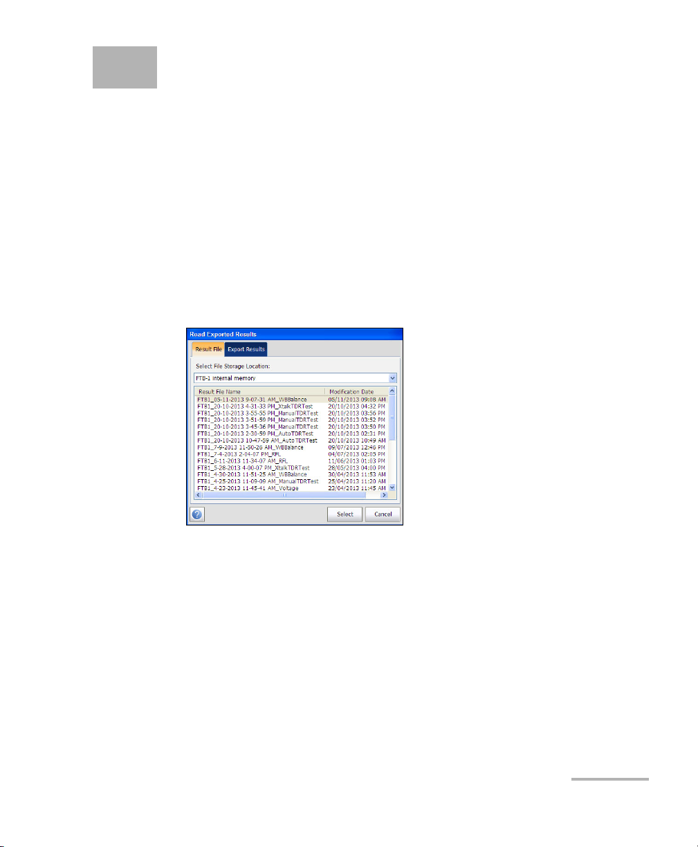
6 Reading and Exporting Saved
Results
You can view and or export any of your saved results by selecting the
Read/Export Results from the Main Menu.
Result File
The Result File page allows you to select a Result File Name and view the
results of files previously saved. The page lists all saved result files by test
date and time. The format of Modification Date is per the selection in
System Settings. Result files can be loaded from either the FTB-1 internal
memory or a USB.
To open previously saved test results:
1. Tap to select the file to open.
2. Ta p Select to open the result file or Cancel to exit the page.
Copper and xDSL Tests 79
Page 88

Reading and Exporting Saved Results
Reading the Result File
Reading the Result File
Once you open a saved result file, you are presented with the saved
measured result details and cable parameters of the selected test. The
following tabs and buttons are displayed dependent on the test saved:
Summary tab displays a list of the names of the executed tests, the
date and time each test was run, and pass/fail status of the test. Refer
to Summary on page 319.
Profile Details displays the thresholds and setup parameters of the
test.
Result Summary displays general information and parameters of the
test under the following tabs:
Save Test displays pass/fail status, general and identification
information, along with comments.
Phone Book displays the phone entries dialed during the test.
Supplemental displays the status, date and time of the last Test
Lead Compensation performed.
80 FTB-635
Page 89

Reading and Exporting Saved Results
Reading the Result File
Profile Details
The Profile Details page displays read-only Test Thresholds and Tes t
Parameters information about the setup of the selected test.
The page displays the following parameters:
Test Grou p is the overall test group of the selected saved results file,
for example Multimeter.
Test Identification is the test type of the group, for example Voltage.
Profile Name is the file name of the selected saved results.
Copper and xDSL Tests 81
Page 90

Reading and Exporting Saved Results
Reading the Result File
Result Summary
The Save Test tab displays pass/fail status, general and identification
information, along with comments, for the test.
General Information displays read-only information pertaining to the
test result.
Result File Name
Test Da te an d Time
Test Gr oup
Test Identification
Test Mo des
Editable Identification Fields display values from the loaded file. You
can edit all fields using the editor screen or by selecting an entry from
the list box.
User Name/ID
Test Fro m /To
Job ID
82 FTB-635
Page 91

Reading and Exporting Saved Results
Reading the Result File
Customer Name
Circuit ID
Comments
Save button keeps any current changes with the current file name.
Save As button saves the current changes under a different file name
that you can configure in the editor screen.
The Save As dialog opens.
The page displays the following parameters:
Result File Storage Location gives you the option of storing results
either in the FTB-1 internal memory or USB device. The default
selection comes from Application Settings/General tab.
Result File Name allows you to preview and edit the result file
name. The proposed file name is based on current auto-naming
parameters configured in Setup/Application Settings/File Name.
Save button confirms your selections.
Cancel button exits the dialog box.
Copper and xDSL Tests 83
Page 92

Reading and Exporting Saved Results
Reading the Result File
Save Report allows you to load a result file, update the ID fields, and
generate a report.
The Save Report dialog opens.
The page displays the following parameters:
Report File Storage Location gives you the option of storing the
report either in the FTB-1 internal memory or USB device. The
default selection comes from Application Settings/General tab.
Report File Name allows you to preview and edit the result file
name. The proposed file name is based on current auto-naming
parameters configured in Setup/Application Settings/File Name.
Report Format allows you to select HTML, MHTML, XML, or PDF
for the generated report.
Save button confirms your selections.
Cancel button exits the dialog box.
Close does not save any changes and closes the page.
84 FTB-635
Page 93
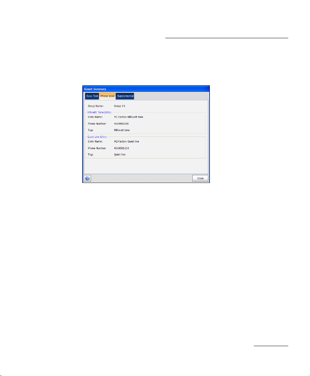
Reading and Exporting Saved Results
Reading the Result File
Phone Book
The Phone Book tab summarizes the Phone Book details when loading a
results file.
It contains information about group entries such as group/Entry name,
phone numbers, and tags.
If the dialer was not used during the test, the Phone Book tab will not
appear as part of the Result Summary page.
Copper and xDSL Tests 85
Page 94

Reading and Exporting Saved Results
Reading the Result File
Supplemental
The Test L ead Comp en satio n under the Supplemental tab displays
read-only Date and Time and Pass/Fail Test Status of the compensated
resistance and capacitance based on the cable temperature of the test
lead.
86 FTB-635
Page 95

Reading and Exporting Saved Results
Export Results
Export Results
The Export Results page allows you to select a Result File Name or Select
All files previously saved and export the results in a selected report format.
The page displays the following parameters:
Select Report Format allows you to select HTML, MHTML, XML, or
PDF for the saved report(s).
Select File Storage Location gives you the option of exporting your
results to either the FTB-1 internal memory or USB device.
Select All allows you to check all file names listed or when not
selected, one or more files to export.
Result File Name lists all the saved result files to format.
Export button transfers the selected file(s) to the internal memory or
USB device in the selected report format.
Cancel button exits the dialog box.
Copper and xDSL Tests 87
Page 96

Page 97

7 Pair Detective Test
The Pair Detective test consists of a series of 10 consecutive individual
tests and applies a high voltage to the line. It automatically analyzes
collected results and gives plain language indications of possible faults.
Before proceeding with this test, ensure the line is inactive.
At the start of any test, the unit checks for the presence of dangerous
voltage and an active circuit. If dangerous voltage is detected, a dialog box
is displayed to inform you and the test will stop. If an active circuit is
detected, a dialog box is displayed to ask you whether or not to proceed
with the test.
Pair Detective
The Pair Detective page displays a summary of the pass/fail status,
DC-Voltage/Current and Isolation for each selected wire pair, as well as
other detailed results of the Pair Detective test.
To access the Pair Detective Page:
1. From the Copper main menu Te st Grou p s, select Pair Detective test
2. From the Te st s menu, select Pair Detective to start the test.
.
Note: Results are not real and for example only.
Copper and xDSL Tests 89
Page 98

Pair Detective Test
Pair Detective
The page allows you to set the following parameters:
Edit Parameters button opens a new page that allows you to set the
soak period of time from 0 to 59 Minutes and 59 Seconds for the
Isolation test. Default is 30 s.
Edit Thresholds button opens a new page that allows you to set the
Pair Detective threshold parameters.
Edit Messages button allows you to edit the error messages in the test.
Select Cable button opens a new page that allows you to set the Cable
Parameters for the test.
Save Test button opens a new page that allows you to save a snapshot
of test results into a result file. Refer Save Test on page 74 for more
information.
90 FTB-635
Page 99

Pair Detective Test
Pair Detect i v e
Setting Test Parameters
The Test Par am eters page allows you to set Test Parameters for the Pair
Detective test.
To set the Test Parameter values:
1. From the Copper main menu Te s t Gr o ups , select Pair Detective test
2. From the Te sts menu, select Pair Detective test.
3. Ta p Edit Parameters button to open the Tes t Par am eters page.
4. Configure the Isolation Soak Time as required.
5. Ta p Close to confirm and exit the page.
.
The page allows you to set the following parameters:
Isolation Soak Time sets a soak period of time from 0 to 59 minutes
and 59 seconds for the Pair Detective test.
Copper and xDSL Tests 91
Page 100

Pair Detective Test
Pair Detective
Setting Threshold Values
The Test T hres h ol ds page allows you to set the Pair Detective threshold
values.
To set the Threshold values:
1. From the Copper main menu Te s t Gr o ups , select Pair Detective test
2. From the Te sts menu, select Pair Detective test.
3. Ta p Edit Thresholds button to open the Tes t Th resh o ld s page.
4. Configure the thresholds as required.
5. Ta p Close to confirm and exit the page.
.
The page allows you to set the following parameters:
Foreign DC Voltage sets the maximum foreign DC voltage value.
POTS DC Voltage sets the minimum working POTS DC voltage value.
POTS DC Current sets the minimum working POTS DC current value.
Capacitive Balance sets the minimum capacitive balance threshold as
a percentage.
Good Balance sets the good balance threshold.
92 FTB-635
 Loading...