

Page 1

Руководство пользователя
EPM-50/ELS-50
Power Meter/Light Source
User Guide
Guide d’utilisation
用户指南
Guía del usuario
Guia do utilizador
Page 2

Copyright © 2010 EXFO Electro-Optical Engineering Inc. All rights reserved. No part
of this publication may be reproduced, stored in a retrieval system or transmitted in
any form, be it electronically, mechanically, or by any other means such as
photocopying, recording or otherwise, without the prior written permission of EXFO
Electro-Optical Engineering Inc. (EXFO).
Information provided by EXFO is believed to be accurate and reliable. However, no
responsibility is assumed by EXFO for its use nor for any infringements of patents or
other rights of third parties that may result from its use. No license is granted by
implication or otherwise under any patent rights of EXFO.
EXFO’s Commerce And Government Entities (CAGE) code under the North Atlantic
Treaty Organization (NATO) is 0L8C3.
The information contained in this publication is subject to change without notice.
Trademarks
EXFO’s trademarks have been identified as such. However, the presence or
absence of such identification does not affect the legal status of any trademark.
Units of Measurement
Units of measurement in this publication conform to SI standards and practices.
Version number: 2.0.0
ii
Page 3

Contents
Certification Information ................................................................................. iv
1 Introducing the EPM-50/ELS-50 ................................................ 1
Main Features ................................................................................................... 1
Power Sources .................................................................................................. 3
Typical Applications .......................................................................................... 3
Conventions ......................................................................................................3
2 Safety Information ................................................................... 4
3 Getting Started ......................................................................... 5
Turning the Unit On and Off ............................................................................. 5
Activating Automatic Shutdown (Auto-Off) ...................................................... 6
Interchanging connector adaptaters .................................................................6
Cleaning and Connecting Optical Fibers ........................................................... 7
4 Measuring Power or Loss (EPM-50) .......................................... 8
Nulling Electrical Offsets ................................................................................... 8
Referencing Your Power Meter to a Source ....................................................... 9
Measuring Power or Loss ................................................................................ 10
5 Using a Light Source (ELS-50) ................................................. 12
Activating/Deactivating a Light Source ........................................................... 12
Modulating the Source Signal ........................................................................ 12
6 Maintenance ............................................................................ 13
Cleaning EUI Connectors ................................................................................ 14
Cleaning Fixed Connectors .............................................................................. 16
Cleaning Detector Ports .................................................................................. 17
Replacing Batteries ......................................................................................... 18
Recalibrating the Unit .....................................................................................18
Recycling and Disposal (Applies to European Union Only) .............................. 19
7 Troubleshooting ...................................................................... 20
Solving Common Problems ............................................................................. 20
Error Codes and Descriptions .......................................................................... 20
Contacting the Technical Support Group ........................................................ 21
Transportation ................................................................................................ 22
8 Warranty .................................................................................. 23
General Information ....................................................................................... 23
Liability ........................................................................................................... 23
Exclusions .......................................................................................................24
Certification .................................................................................................... 24
Service and Repairs ......................................................................................... 25
EXFO Service Centers Worldwide .................................................................... 26
A Technical Specifications .......................................................... 27
EPM-50/ELS-50 iii
Page 4

Certification Information iv
Certification Information
F.C.C. Information
Electronic test equipment is exempt from Part 15 compliance (FCC) in the United
States. However, compliance verification tests are systematically performed on
most EXFO equipment.
Information
Electronic test equipment is subject to the EMC Directive in the European Union.
The EN61326 standard prescribes both emission and immunity requirements for
laboratory, measurement, and control equipment. This unit has undergone
extensive testing according to the European Union Directive and Standards.
DECLARATION OF CONFORMITY
Application of Council Directive(s): 2004/108/EC - The EMC Directive
Manufacturer’s Name: EXFO Electro-Optical Engineering Inc.
Manufacturer’s Address: 400 Godin Avenue
Quebec, Quebec
(418) 683-0211
Equipment Type/Environment: Test & Measurement / Industrial
Trade Name/Model No.: EPM-50 / Power Meter
Standard(s) to which Conformity is Declared:
EN 61326-1:2006 Electrical Equipment for Measurement, Control and Laboratory
EN 60825-1:2007 Edition 2.0 Safety of laser products – Part 1: Equipment classification and
EN 55022: 2006 + A1: 2007 Information technology equipment — Radio disturbance
I, the undersigned, hereby declare that the equipment specified above conforms to the above Directive and Standards.
Manufacturer
Signature:
Full Name: Stephen Bull, E. Eng
Position: Vice-President Research and
Address: 400 Godin Avenue, Quebec (Quebec),
Date: December 03, 2009
Development
Canada, G1M 2K2
Use - EMC Requirements
requirements
characteristics — Limits and methods of measurement
2006/66/EC - The Battery Directive
93/68/EEC - CE Marking
And their amendments
Canada, G1M 2K2
ELS-50 / Light Source
Page 5

1 Introducing the
EPM-50/ELS-50
This user guide covers the following products (unless otherwise specified,
descriptions apply to all):
³ EPM-50 Power Meter
³ ELS-50 Light Source
Main Features
The EPM-50 Power Meter offers:
³ a rugged design
³ Interchangeable connector adapters
³ 300 hours of battery life
³ tone recognition for fiber identification
³ a universal push-pull interface
³ reference function for direct loss measurements
The ELS-50 Light Source offers:
³ a rugged design
³ excellent power stability for reliable loss measurements
³ interchangeable connectors interface
³ up to 60 hours of battery life
³ interchangeable connector adapters
³ tone generation for fiber identification
EPM-50/ELS-50 1
Page 6
Introducing the EPM-50/ELS-50 2
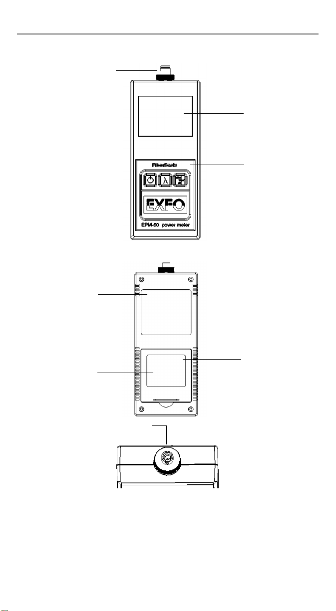
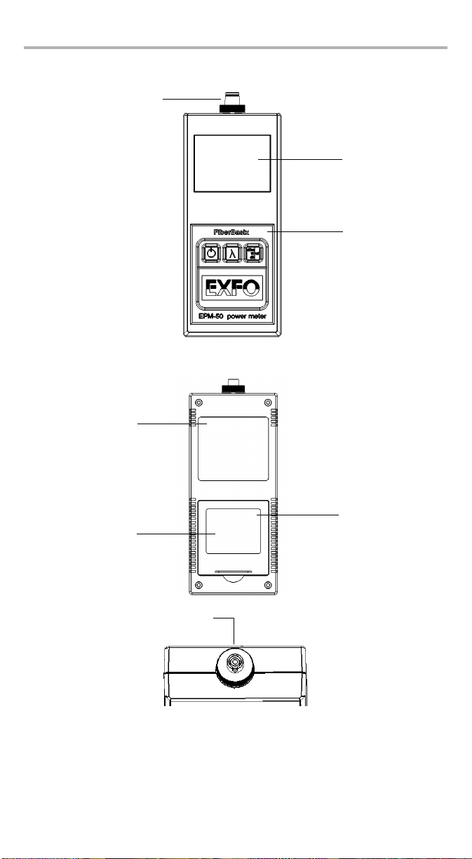
Front View
Protector Cap
LCD display
Keypad
(EPM-50 shown)
Back View
Safety label and
serial number
Battery compartment
(3 alkaline or
rechargeable
batteries)
Connector port
Quick reference
label
Page 7

Power Sources
The units operate with 3 AA alkaline or rechargeable batteries.
IMPORTANT
If the battery level becomes too low, the unit turns itself off.
Typical Applications
The units offer specific typical applications.
EPM-50 Power Meter:
³ High power model for CATV and Telco applications
³ Enterprise/LAN for singlemode and multimode measurements
ELS-50 Light Source:
³ Telco/CATV and FTTH models; dual and triple wavelenghts
³ Enterprise/LAN models; singlemode and multimode
Conventions
Before using the product described in this manual, you should understand the
following conventions:
WARNING
Indicates a potentially hazardous situation which, if not avoided,
could result in death or serious injury. Do not proceed unless you
understand and meet the required conditions.
CAUTION
Indicates a potentially hazardous situation which, if not avoided,
may result in minor or moderate injury. Do not proceed unless you
understand and meet the required conditions.
CAUTION
Indicates a potentially hazardous situation which, if not avoided,
may result in component damage. Do not proceed unless you
understand and meet the required conditions.
IMPORTANT
Refers to information about this product you should not overlook.
EPM-50/ELS-50 3
Page 8
Safety Information 4
2 Safety Information
WARNING
Do not install or terminate fibers while a laser source is active. Never
look directly into a live fiber and ensure that your eyes are protected
at all times.
WARNING
Use of controls, adjustments and procedures for operation and
maintenance other than those specified herein may result in
hazardous radiation exposure.
Your instrument is a Class 1 laser product in compliance with standards IEC 60825-1
and 21 CFR 1040.10. Laser radiation may be encountered at the output port.
The following label indicates that a product contains a Class 1 source:
CLASS 1
LASER PRODUCT
Note: The label is affixed to your product.
Page 9
3 Getting Started
Turning the Unit On and Off
When you turn off the EPM-50, it saves the current wavelength, unit and reference
power.
IMPORTANT
If you remove the batteries, the unit will turn off without saving the
above values.
If batteries are low, the unit will save the above values and turn off.
Note: Offset nulling values are always returned to factory settings.
To turn on the unit:
Press . You may use the unit immediately under normal conditions.
To turn off the unit:
From normal operating mode, hold down a few seconds.
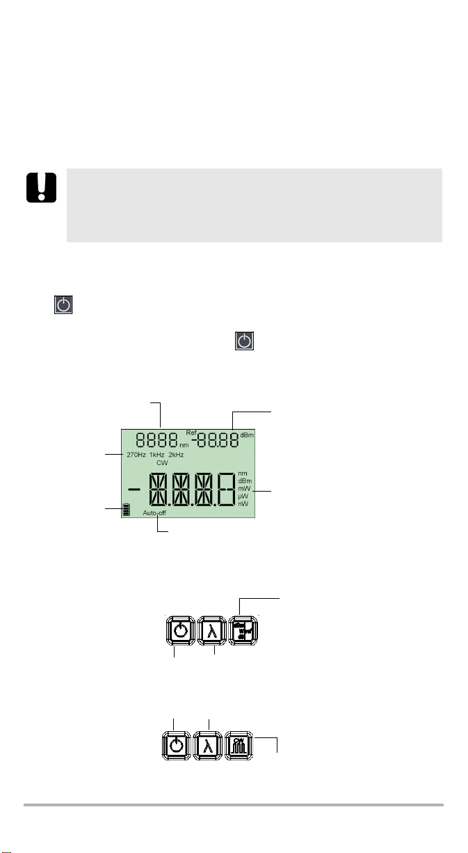
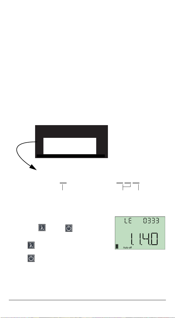
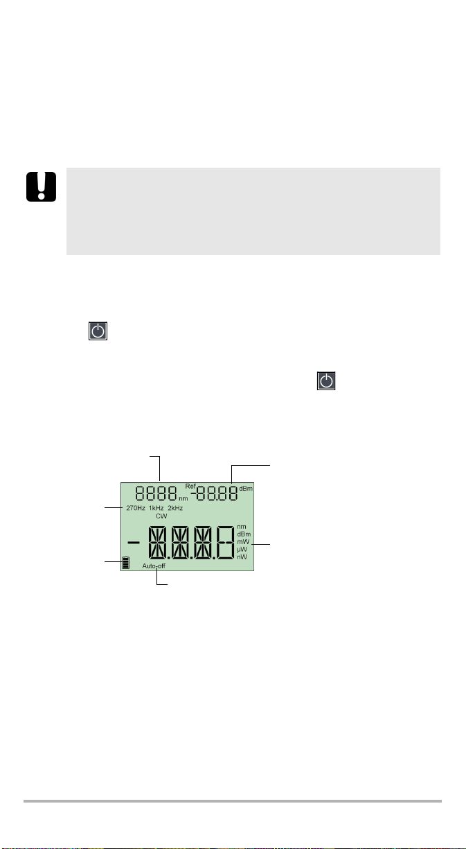
Display
Power meter wavelength
modulation
Detected
modulation
(EPM-50)
Batteries level
(EPM-50)
Source
(ELS-50)
Auto-off activated
Reference power (EPM-50)
Measured power/loss (EPM-50)
Active source wavelength (ELS-50)
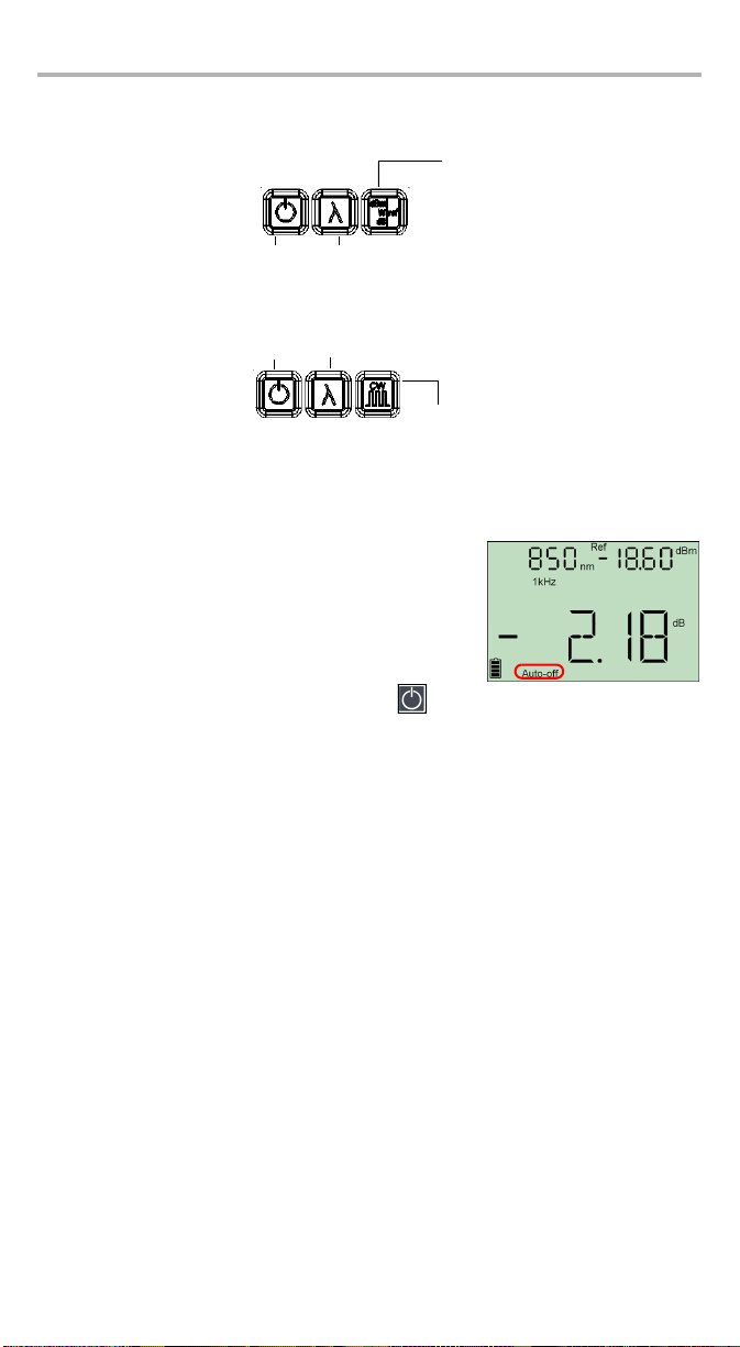
Keypad
PRESS: Switches between
units
EPM-50
HOLD: Turns unit on/off
PRESS: Controls
auto-off
PRESS: Exits special
modes
PRESS: Changes
wavelengths
PRESS: Activates next source
HOLD: Deactivates current source
HOLD: Sets input power as
reference power
ELS-50
PRESS: Switches between
modulation values
EPM-50/ELS-50 5
Page 10
Getting Started 6
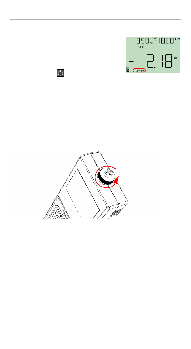
Activating Automatic Shutdown (Auto-Off)
When auto-off is activated, the unit will turn off after
10 minutes of idle time.
Auto-off is activated by default when you turn on the
unit.
To deactivate/reactivate auto-off:
When unit is on, press .
Note: Auto-off is automatically disabled when you perform an offset nulling.
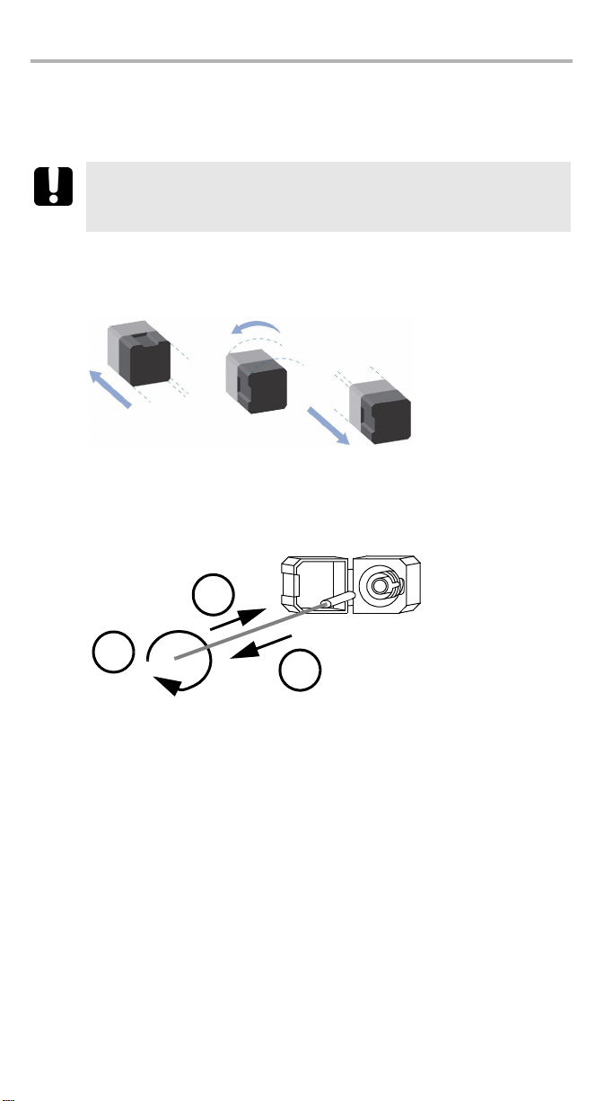
Changing Connector Adapters
The connector adapters are optional accessories available on the EPM-50 Power
Meter and ELS-50 Light Source. Depending on the type of connector on the fiber you
need to test, you might have to change them.
To change connector adapters:
1. Hold the unit so the connector port is facing you.
2. Turn the connector adapter counterclockwise to unscrew it.
3. Screw in the adapter you want to use.
Page 11

Cleaning and Connecting Optical Fibers
IMPORTANT
To ensure maximum power and to avoid erroneous readings:
³ Always clean fiber ends as explained below before inserting
them into the port. EXFO is not responsible for damage or errors
caused by bad fiber cleaning or handling.
³ Ensure that your patchcord has appropriate connectors. Joining
mismatched connectors will damage the ferrules.
To connect the fiber-optic cable to the port:
1. Inspect the fiber using a fiber inspection microscope. If the fiber is clean,
proceed to connecting it to the port. If the fiber is dirty, clean it as explained
below.
2. Clean the fiber ends as follows:
2a. Gently wipe the fiber end with a lint-free swab dipped in isopropyl alcohol.
2b. Use compressed air to dry completely.
2c. Visually inspect the fiber end to ensure its cleanliness.
3. Carefully align the connector and port to prevent the fiber end from touching the
outside of the port or rubbing against other surfaces.
If your connector features a key, ensure that it is fully fitted into the port’s
corresponding notch.
4. Push the connector in so that the fiber-optic cable is firmly in place, thus
ensuring adequate contact.
If your connector features a screwsleeve, tighten the connector enough to firmly
maintain the fiber in place. Do not overtighten, as this will damage the fiber and
the port.
Note: If your fiber-optic cable is not properly aligned and/or connected, you
will notice heavy loss and reflection.
EPM-50/ELS-50 7
Page 12

Measuring Power or Loss (EPM-50) 8
4 Measuring Power or Loss
(EPM-50)
Nulling Electrical Offsets
Temperature and humidity variations affect the performance of electronic circuits
and optical detectors. Nulling the electrical offsets eliminates these effects. Your un i t
has been designed not to require offset nulling under normal operation, but you
should perform it whenever environmental conditions change significantly or when
measuring very low power values.
IMPORTANT
If light reaches the detector when nulling offsets, LIGH appears on
the display and the nulling is not performed. You will need to press a
key to return to the previous display.
Note: Factory-defined values will be reinstated when you turn off the unit.
To perform an offset nulling:
Hold down and a few seconds. The unit
displays NULL while nulling the offsets, then returns to
normal mode.
Note: Keypad is disabled during the operation.
Page 13
Referencing Your Power Meter to a Source
In reference mode, your unit displays the loss created by the fiber under test only,
since a reference value is subtracted from the measured power.
Note: You must set a reference value separately for each wavelength.
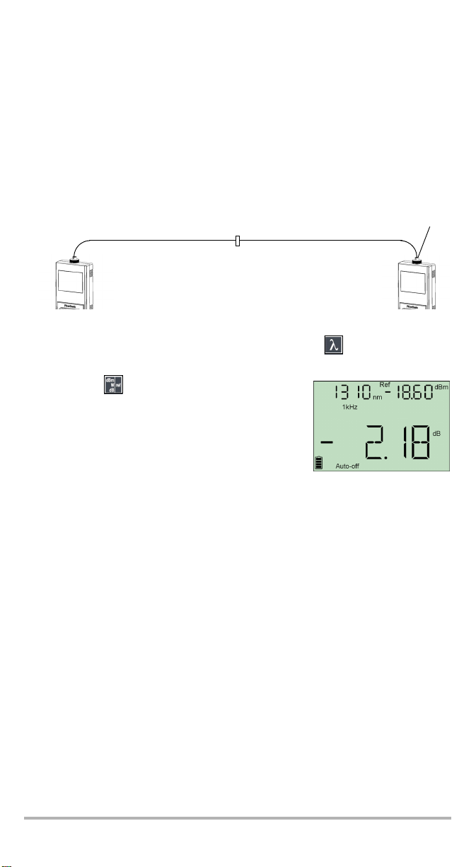
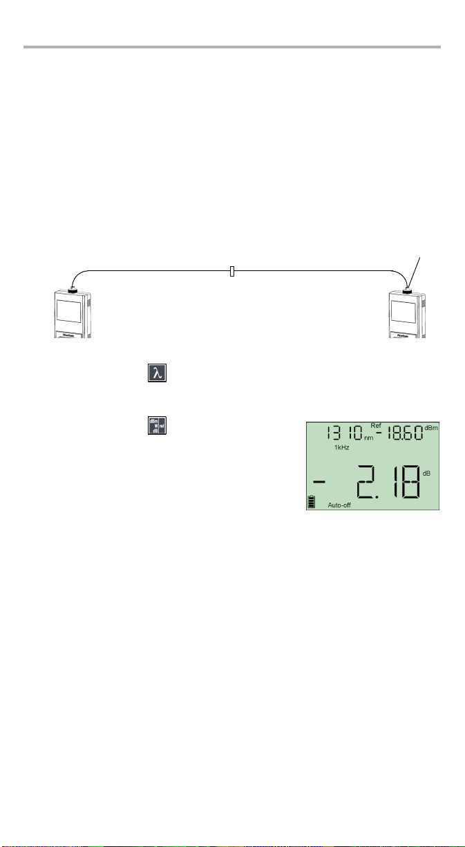
To reference the power meter to a source manually:
1. Using the proper adapter, connect a light source (such as ELS-50) to the
detector port of your power meter.
Reference
test jumper
Power
meter
Light
source
test jumper
Bulkhead
connector
2. Activate the source at the desired wavelength.
3. Match the source and power meter wavelenghts using .
Wavelength is displayed in the top left corner.
4. Hold down for a few seconds. The power meter
stores the currently detected power as the new
reference power.
Reference power is displayed in the top right corner
(in dBm) and current loss reading is automatically
switched to dB.
5. Repeat the procedure for each wavelength you want to reference.
AdapterReference
Note: Once all desired wavelengths have been referenced, do not disconnect
the Reference Test Jumper from the source port until all measurements
have been done.
EPM-50/ELS-50 9
Page 14
Measuring Power or Loss (EPM-50) 10
Measuring Power or Loss
Measuring absolute power is done the same way as referencing the power meter to
a source, except for the referencing step.
To perform power or loss measurements:
1. If necessary, perform an offset nulling (see Nulling Electrical Offsets on page 8).
2. Check and clean your fibers appropriately for optimum performance
(see Cleaning and Connecting Optical Fibers on page 7).
3. For loss measurements, reference your power meter to a light source
(see Referencing Your Power Meter to a Source on page 9), then deactivate the
light source.
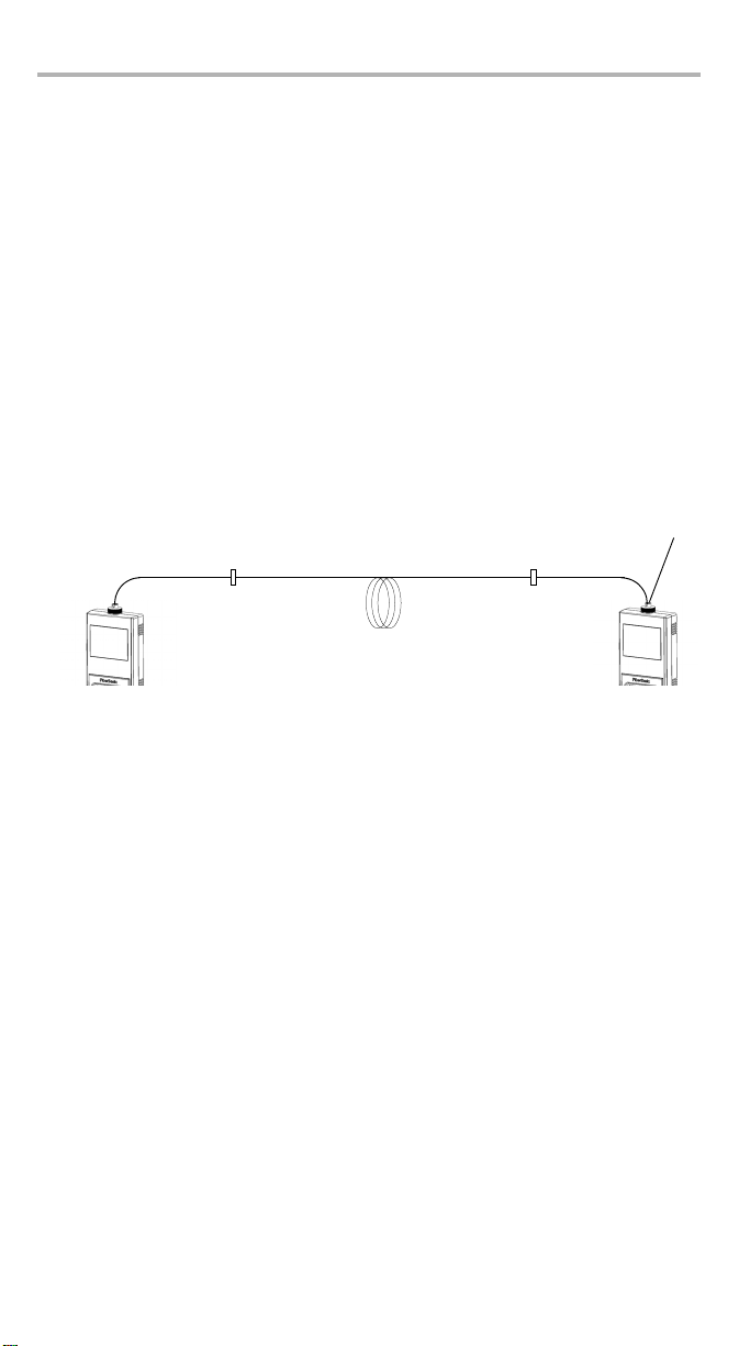
4. Using the proper adapter and test jumpers, connect a fiber under test to a light
source (such as ELS-50) and to the detector port of your unit.
Note: If you have referenced your power meter to a source, simply connect a
fiber under test to the test jumpers used for referencing.
Te st
jumper
Light
source
Bulkhead
connector
Fiber under test
jumper
Bulkhead
connector
Power
meter
Te st
Adapter
Page 15
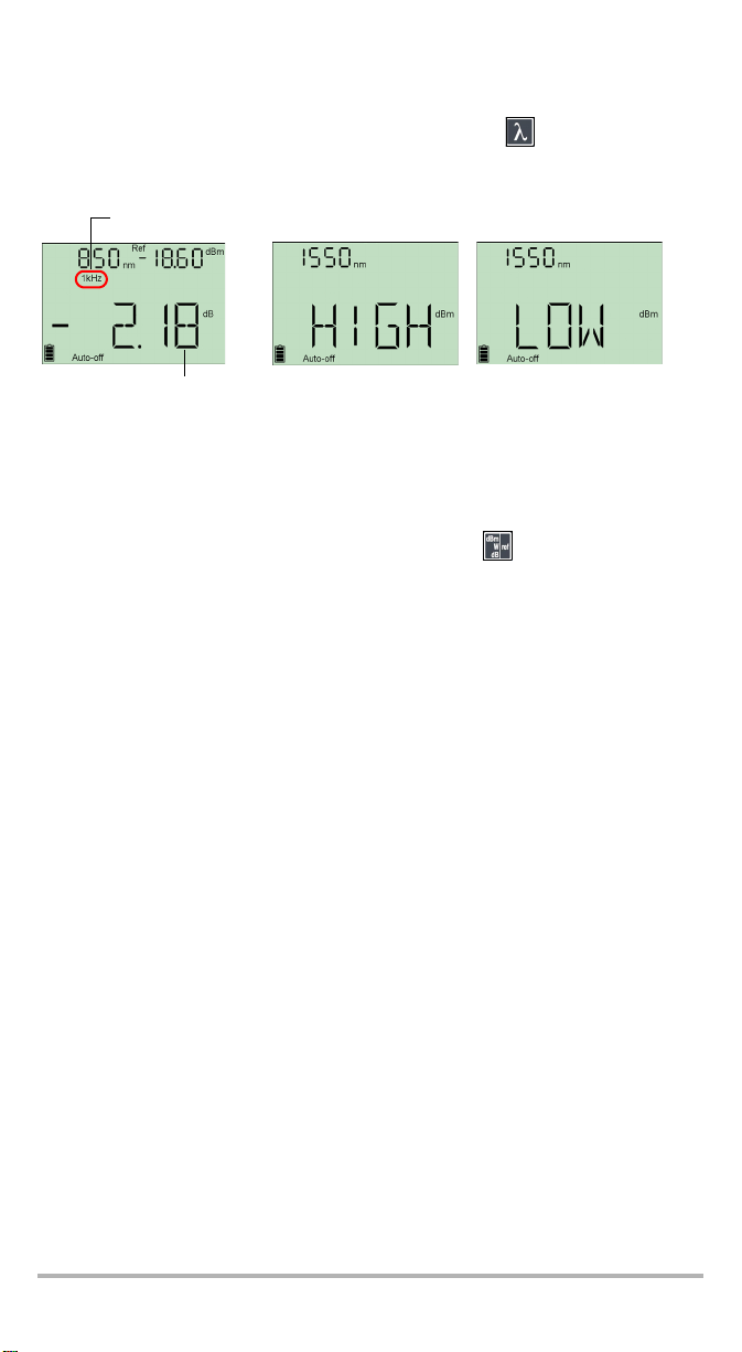
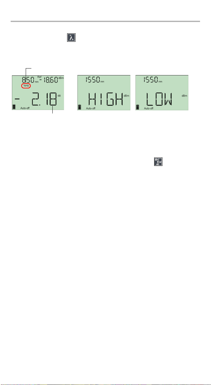
5. Activate the source at the desired wavelength.
6. Match the source and power meter wavelengths using .
Modulation detected
Actual power
or loss
of fiber under test
When power or loss is outside power limits
(see Technical Specifications on page 27)
When the unit detects a modulated signal, it displays the modulation value and
average measured power or loss (see left illustration above). You may notice a
slightly unstable last digit.
7. If necessary, change the displayed units by pressing .
8. Repeat the procedure for other wavelengths.
EPM-50/ELS-50 11
Page 16
Using a Light Source (ELS-50) 12
5 Using a Light Source
(ELS-50)
The ELS-50 may contain up to three sources.
Activating/Deactivating a Light Source
Only one source may be active at a time. When no source is active, the unit displays
OFF and leaves the top left corner empty.
To activate a light source and change the wavelength:
Press
and modulation.
To deactivate the light source:
³ Press
³ Hold down
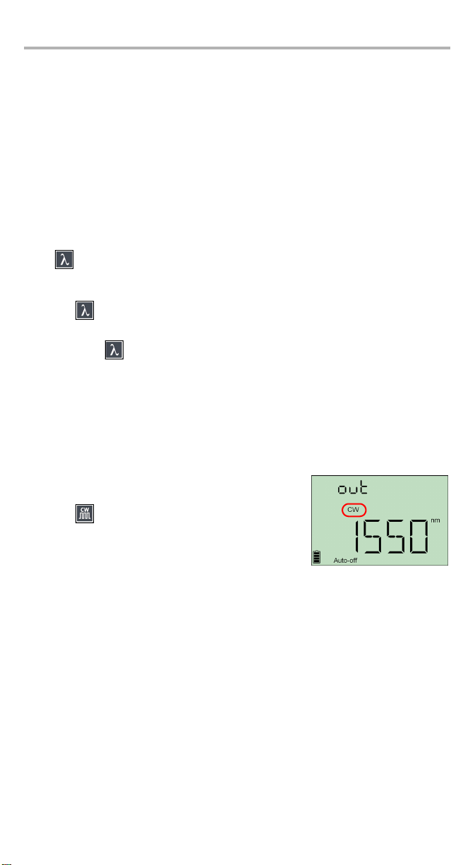
Modulating the Source Signal
When you activate the first source, the signal is always CW (unmodulated). When
you switch sources, the modulation remains the same. Modulation is indicated in
the top left corner.
Available modulation values are: CW, 270 Hz, 1 kHz and 2 kHz.
To change the signal modulation:
1. Activate the source.
2. Press to switch between available modulations.
to activate each available source in turn. The unit displays the wavelength
until you get past the last source.
OR
a few seconds.
Note: When the output signal is modulated
(270Hz, 1kHz, 2kHz), you will notice the
mention out blinking in the top left corner of the display.
Page 17

6 Maintenance
This product contains no user-serviceable parts. However, it contains sensitive
electronic and optical components, and should be handled carefully and stored in
its carrying case when not in use.
To help ensure long, trouble-free operation:
³ Always inspect fiber-optic connectors before using them and clean them if
necessary.
³ Keep the unit free of dust.
³ Clean the unit casing and front panel with a cloth slightly dampened with water.
³ Store unit at room temperature in a clean and dry area. Keep the unit out of
direct sunlight.
³ Avoid high humidity or significant temperature fluctuations.
³ Avoid unnecessary shocks and vibrations.
³ If any liquids are spilled on or into the unit, turn off the power immediately,
disconnect from any external power source, remove the batteries and let the
unit dry completely.
WARNING
Use of controls, adjustments, and procedures for operation and
maintenance other than those specified herein may result in
hazardous radiation exposure.
EPM-50/ELS-50 13
Page 18
Maintenance 14
Cleaning EUI Connectors
Regular cleaning of EUI connectors will help maintain optimum performance. There
is no need to disassemble the unit.
IMPORTANT
If any damage occurs to internal connectors, the module casing will
have to be opened and a new calibration will be required.
To clean EUI connectors:
1. Remove the EUI from the instrument to expose the connector baseplate and
ferrule.
Tur n
Push
2. Moisten a 2.5 mm cleaning tip with one drop of isopropyl alcohol (alcohol may
leave traces if used abundantly).
3. Slowly insert the cleaning tip into the EUI adapter until it comes out on the other
side (a slow clockwise rotating movement may help).
Pull
3
4
5
4. Gently turn the cleaning tip one full turn, then continue to turn as you withdraw
it.
Page 19

5. Repeat steps 3 to 4 with a dry cleaning tip.
Note: Make sure you don’t touch the soft end of the cleaning tip.
6. Clean the ferrule in the connector port as follows:
6a. Deposit one drop of isopropyl alcohol on a lint-free wiping cloth.
IMPORTANT
Since isopropyl alcohol is not absolutely pure, it may leave residues
if used abundantly or left to evaporate (about 10 seconds).
Avoid contact between the tip of the bottle and the wiping cloth,
dry the surface quickly, and use a bottle that distributes only a drop
of alcohol at a time.
6b. Gently wipe the connector and ferrule.
6c. With a dry lint-free wiping cloth, gently wipe the same surfaces to ensure
that the connector and ferrule are perfectly dry.
6d. Verify connector surface with a portable fiber-optic microscope (for
example, EXFO’s FOMS) or fiber inspection probe (for example, EXFO’s
FIP).
WARNING
Verifying the surface of the connector WHILE THE UNIT IS ACTIVE
WILL result in permanent eye damage.
7. Put the EUI back onto the instrument (push and turn clockwise).
8. Throw out cleaning tips and wiping cloths after one use.
EPM-50/ELS-50 15
Page 20

Maintenance 16
Cleaning Fixed Connectors
Regular cleaning of connectors will help maintain optimum performance. Do not try
to disassemble the unit. Doing so would break the connector.
To clean fixed connectors:
1. Fold a lint-free wiping cloth in four to form a square.
2. Moisten the center of the lint-free wiping cloth with only one drop of isopropyl
alcohol.
IMPORTANT
Alcohol may leave traces if used abundantly. Avoid contact between
the tip of the bottle and the wiping cloth, and do not use bottles
that distribute too much alcohol at a time.
3. Gently wipe the connector threads three times with the folded and moistened
section of the wiping cloth.
IMPORTANT
Isopropyl alcohol takes approximately ten seconds to evaporate.
Since isopropyl alcohol is not absolutely pure, evaporation will leave
microscopic residue. Make sure you dry the surfaces before
evaporation occurs.
4. With a dry lint-free wiping cloth, gently wipe the same surfaces three times with
a rotating movement.
5. Throw out the wiping cloths after one use.
6. Moisten a cleaning tip (2.5 mm tip) with only one drop of isopropyl alcohol.
IMPORTANT
Alcohol may leave traces if used abundantly. Avoid contact between
the tip of the bottle and the cleaning tip, and do not use bottles that
distribute too much alcohol at a time.
7. Slowly insert the cleaning tip into the connector until it reaches the ferrule
inside (a slow clockwise rotating movement may help).
7
8
9
8. Gently turn the cleaning tip one full turn.
Page 21

9. Continue to turn as you withdraw the cleaning tip.
10. Repeat steps 7 to 9, but this time with a dry cleaning tip (2.5 mm tip provided by
EXFO).
Note: Make sure you don’t touch the soft end of the cleaning tip and verify the
cleanliness of the cotton tip.
11. Throw out the cleaning tips after one use.
Cleaning Detector Ports
Regular cleaning of detectors will help maintain measurement accuracy.
IMPORTANT
Always cover detectors with protective caps when unit is not in use.
To clean detector ports:
1. Remove the protective cap and adapter (FOA) from the detector.
2. If the detector is dusty, blow dry with compressed air.
3. Being careful not to touch the soft end of the swab, moisten a cleaning tip with
only one drop of isopropyl alcohol.
IMPORTANT
Alcohol may leave traces if used abundantly. Do not use bottles that
distribute too much alcohol at a time.
4. While applying light pressure (to avoid breaking the detector window), gently
rotate the cleaning tip on the detector window.
5. Repeat step 4 with a dry cleaning tip or blow dry with compressed air.
6. Discard the cleaning tips after one use.
EPM-50/ELS-50 17
Page 22
Maintenance 18
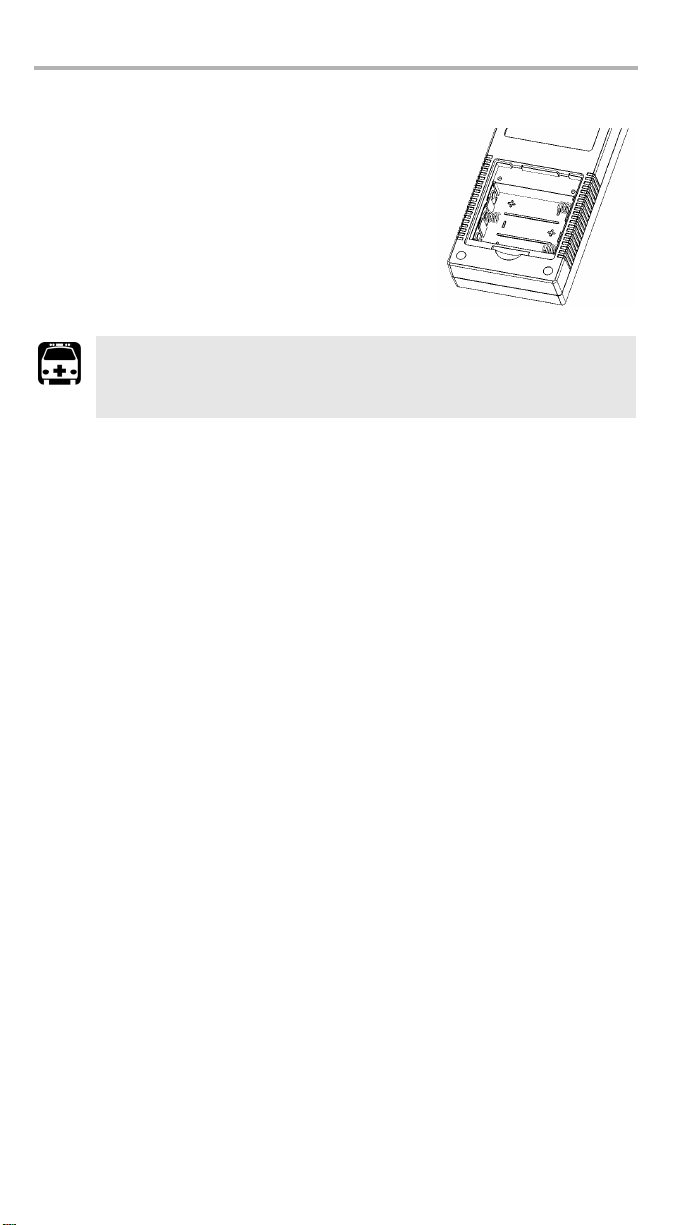
Replacing Batteries
Your unit requires three AA alkaline or rechargeable
batteries.
To replace batteries:
1. Turn off the unit.
2. Open the battery compartment door located at the
back of the unit.
3. Replace batteries, respecting the polarity as shown.
4. Close the battery compartment door.
WARNING
Do not throw batteries into fire or water and do not short-circuit
the batteries’ electrical contacts. Do not disassemble.
Recalibrating the Unit
Manufacturing and service center calibrations are based on the ISO/IEC 17025
Standard, which states that calibration documents must not contain a
recommended calibration interval, unless this has been previously agreed upon
with the customer.
Validity of specifications depends on operating conditions. For example, the
calibration validity period can be longer or shorter depending on the intensity of use,
environmental conditions and unit maintenance. You should determine the
adequate calibration interval for your unit according to your accuracy requirements.
Under normal use, EXFO recommends calibrating your unit every year.
Note: The FlexCare warranty program includes Calibration/Verification
Note: Recalibration only applies to the EPM-50 Power Meter.
packages (see Service and Repairs on page 25).
Page 23

Recycling and Disposal (Applies to European
Union Only)
Recycle or dispose of your product (including electric and electronic
accessories) properly, in accordance with local regulations. Do not
dispose of it in ordinary garbage receptacles.
This equipment was sold after August 13, 2005 (as identified by the
black rectangle).
³ Unless otherwise noted in a separate agreement between EXFO and a
customer, distributor or commercial partner, EXFO will cover costs related to
the collection, treatment, recovery and disposal of end-of-lifecycle waste
generated by electronic equipment introduced after August 13, 2005 to an
European Union member state with legislation regarding Directive 2002/96/EC.
³ Except for reasons of safety or environmental benefit, equipment manufactured
by EXFO, under its brand name, is generally designed to facilitate dismantling
and reclamation.
For complete recycling/disposal procedures and contact information, visit the EXFO
Web site at www.exfo.com/recycle.
EPM-50/ELS-50 19
Page 24

Troubleshooting 20
7 Troubleshooting
Solving Common Problems
Problem Possible Cause Solution
The unit does not turn on. Batteries are discharged. Replace batteries.
Reference power different than
source output power.
Error Codes and Descriptions
ER: error code displayed until you press a key.
Received power outside
detector’s range.
Change source output
power.
Error
Code
LIGH
Light detected while nulling offsets.
(EPM-50
Nulling is not performed.
only)
3/11 Embedded software problem. Contact EXFO.
7 Hardware problem. Replace unit.
13 Non-volatile memory corrupted
(would occur during unit
initialization).
Description Solution
Correctly place protective cap on
detector port, then retry.
³ Hold down all 3 buttons during
initialization to reset unit.
³ Unit must be recalibrated.
Contact EXFO.
Page 25
Contacting the Technical Support Group
To obtain after-sales service or technical support for this product, contact EXFO at
one of the following numbers. The Technical Support Group is available to take your
calls from Monday to Friday, 8:00 a.m. to 7:00 p.m. (Eastern Time in North America).
For detailed information about technical support, visit the EXFO Web site at
www.exfo.com.
Technical Support Group
400 Godin Avenue
Quebec (Quebec) G1M 2K2
CANADA
To accelerate the process, please have information such as the name and the serial
number (see the product identification label—an example is shown below), as well
as a description of your problem, close at hand.
1 866 683-0155 (USA and Canada)
Tel.: 1 418 683-5498
Fax: 1 418 683-9224
support@exfo.com
P/N
**************** A
542392-3D
S/N
Made in Canada QST442B
January 2020
EPM-50XX
Detector
type
Ver.
Mfg.
date
465 Godin Avenue
Vanier (Quebec) G1M 3G7 CANADA
ELS-50-XX-XX-XX
Source
ports
Source
connector
You may also be requested to provide the embedded software version numbers.
To display the embedded software version, the
manufacturing date, and the serial number:
1. Hold down
The unit displays the main embedded software
and press at the same time.
version.
2. Press again to view the serial number and
manufacturing date.
3. Press to return to normal mode.
EPM-50/ELS-50 21
Page 26

Troubleshooting 22
Transportation
Maintain a temperature range within specifications when transporting the unit.
Transportation damage can occur from improper handling. The following steps are
recommended to minimize the possibility of damage:
³ Pack the unit in its original packing material when shipping.
³ Avoid high humidity or large temperature fluctuations.
³ Keep the unit out of direct sunlight.
³ Avoid unnecessary shocks and vibrations.
Page 27

8 Warranty
General Information
EXFO Electro-Optical Engineering Inc. (EXFO) warrants this equipment against
defects in material and workmanship for a period of one year from t
shipment. EXFO also warrants that this equipment will meet applicable
original
specifications under normal use.
During the warranty period, EXFO will, at its discretion, repair, replace, or issue
credit for any defective product, as well as verify and adjust the product free of
charge should the equipment need to be repaired or if the original calibration is
erroneous. If the equipment is sent back for verification of calibration during the
warranty period and found to meet all published specifications, EXFO will charge
standard calibration fees.
IMPORTANT
The warranty can become null and void if:
³ unit has been tampered with, repaired, or worked upon by
unauthorized individuals or non-EXFO personnel.
³ warranty sticker has been removed.
³ case screws, other than those specified in this guide, have been
removed.
³ case has been opened, other than as explained in this guide.
³ unit serial number has been altered, erased, or removed.
³ unit has been misused, neglected, or damaged by accident.
he date of
THIS WARRANTY IS IN LIEU OF ALL OTHER WARRANTIES EXPRESSED, IMPLIED,
OR STATUTORY, INCLUDING, BUT NOT LIMITED TO, THE IMPLIED WARRANTIES OF
MERCHANTABILITY AND FITNESS FOR A PARTICULAR PURPOSE. IN NO EVENT
SHALL EXFO BE LIABLE FOR SPECIAL, INCIDENTAL, OR CONSEQUENTIAL
DAMAGES.
Liability
EXFO shall not be liable for damages resulting from the use of the product, nor shall
be responsible for any failure in the performance of other items to which the
product is connected or the operation of any system of which the product may be a
part.
EXFO shall not be liable for damages resulting from improper usage or unauthorized
modification of the product, its accompanying accessories and software.
EPM-50/ELS-50 23
Page 28

Warranty 24
Exclusions
EXFO reserves the right to make changes in the design or construction of any of its
products at any time without incurring obligation to make any changes whatsoever
on units purchased. Accessories, including but not limited to fuses, pilot lamps,
batteries and universal interfaces (EUI) used with EXFO products are not covered by
this warranty.
This warranty excludes failure resulting from: improper use or installation, normal
wear and tear, accident, abuse, neglect, fire, water, lightning or other acts of nature,
causes external to the product or other factors beyond EXFO’s control.
IMPORTANT
EXFO will charge a fee for replacing optical connectors that were
damaged due to misuse or bad cleaning.
Certification
EXFO certifies that this equipment met its published specifications at the time of
shipment from the factory.
Page 29

Service and Repairs
EXFO commits to providing product service and repair for five years following the
date of purchase.
To send any equipment for service or repair:
1. Call one of EXFO’s authorized service centers (see EXFO Service Centers
Worl dw id e on page 26). Support personnel will determine if the equipment
requires service, repair, or calibration.
2. If equipment must be returned to EXFO or an authorized service center, support
personnel will issue a Return Merchandise Authorization (RMA) number and
provide an address for return.
3. If possible, back up your data before sending the unit for repair.
4. Pack the equipment in its original shipping material. Be sure to include a
statement or report fully detailing the defect and the conditions under which it
was observed.
5. Return the equipment, prepaid, to the address given to you by support
personnel. Be sure to write the RMA number on the shipping slip. EXFO will
refuse and return any package that does not bear an RMA number.
Note: A test setup fee will apply to any returned unit that, after test, is found to
meet the applicable specifications.
After repair, the equipment will be returned with a repair report. If the equipment is
not under warranty, you will be invoiced for the cost appearing on this report. EXFO
will pay return-to-customer shipping costs for equipment under warranty. Shipping
insurance is at your expense.
Routine recalibration is not included in any of the warranty plans. Since
calibrations/verifications are not covered by the basic or extended warranties, you
may elect to purchase FlexCare Calibration/Verification Packages for a definite
period of time. Contact an authorized service center (see EXFO Service Centers
Worl dw id e on page 26).
EPM-50/ELS-50 25
Page 30

Warranty 26
EXFO Service Centers Worldwide
If your product requires servicing, contact your nearest authorized service center.
EXFO Headquarters Service Center
400 Godin Avenue
Vanier (Quebec) G1M 2K2
CANADA
EXFO Europe Service Center
Le Dynasteur
10/12, rue Andras Beck
92366 Meudon la Forêt Cedex
FRANCE
EXFO China Service Center/
Beijing OSIC
Beijing New Century Hotel
Office Tower, Room 1754-1755
No. 6 Southern Capital Gym Road
Beijing 100044
P. R . C H I N A
1 866 683-0155 (USA and Canada)
Tel.: 1 418 683-5498
Fax: 1 418 683-9224
quebec.service@exfo.com
Tel.: +33.1.40.83.85.85
Fax: +33.1.40.83.04.42
europe.service@exfo.com
Tel.: +86 (10) 6849 2738
Fax: +86 (10) 6849 2662
beijing.service@exfo.com
Page 31

A Technical Specifications
OPTIONAL ACCESSORIES
PMA-22 (FC connector adapter for EPM-50 power meter)
PMA-32 (ST connector adapter for EPM-50 power meter)
PMA-54 (SC connector adapter for EPM-50 power meter)
STANDARD ACCESSORIES
Soft pouch, PMA-22 FC connector adapter, quick reference sticker in five languages,
Certificate of Calibration, Certificate of Compliance, three AA batteries
GENERAL SPECIFICATIONS
Size (H x W x D)
189 mm x 78 mm x 37 mm (7 7/16 in x 3 1/16 in x 1 7/16 in)
Weight
0.4 kg (0.9 lb)
Temperature operating
—10 °C to 50 °C (14 °F to 122 °F)
storage
—40 °C to 70 °C (–40 °F to 158 °F)
Relative humidity
0 % to 95 % non-condensing
SPECIFICATIONS
a
MODEL EPM-53 EPM-53X
Power meter port
InGaAs InGaAsX
Power range b (dBm)
10 to –60 26 to –50
Number of calibrated wavelengths
c
55
Power uncertainty
d
±5 % ±5 %
Resolution (dB)
0.01 0.01
Display units
dB/dBm/W dB/dBm/W
Tone detection (Hz)
270, 1 k, 2 k 270, 1 k, 2 k
Battery life (hours)
d
>300 >300
Warranty (year)
11
IMPORTANT
The following technical specifications can change without notice.
The information presented in this section is provided as a reference
only. To obtain this product’s most recent technical specifications,
visit the EXFO Web site at www.exfo.com.
EPM-50 Specifications
Notes
a. All specifications valid at 23 °C ± 3 °C, with an FC/UPC connector
b. In CW mode
c. Wavelengths: 850 nm, 1300 nm, 1310 nm, 1490 nm, 1550 nm
d. Typical
EPM-50/ELS-50 27
Page 32

Technical Specifications 28
SPECIFICATIONS
MODEL
23BL
235BL
12C
Central wavelength (nm)
b
b, c
b, d
b
Tone generation (Hz)
Warranty (year)
STANDARD ACCESSORIES
Soft pouch, LSA-89 FC connector adapter, quick reference sticker in five languages,
Certificate of Compliance, three AA batteries
GENERAL SPECIFICATIONS
Size (H x W x D)
189 mm x 78 mm x 37 mm (7 7/16 in x 3 1/16 in x 1 7/16 in)
Weight
0.4 kg (0.9 lb)
Temperature operating
storage
—10 °C to 50 °C (14 °F to 122 °F)
—40 °C to 70 °C (–40 °F to 158 °F)
Relative humidity
0 % to 95 % non-condensing
OPTIONAL ACCESSORIES
LSA-89 (FC connector adapter for ELS-50 Light Source)
LSA-90 (ST connector adapter for ELS-50 Light Source)
LSA-91 (SC connector adapter for ELS-50 Light Source)
ELS-50 Specifications
Notes
a. All specifications valid at 23 °C ± 3 °C, with an FC/UPC connector
b. Typical
c. rms for lasers and —3 dB width for LEDs
d. After 15 minutes warmup; expressed as ± half the difference between the maximum and minimum values measured
over 8 hours
Page 33

NOTICE
抩⛙
CHINESE REGULATION ON RESTRICTION OF HAZARDOUS SUBSTANCES
NAMES AND CONTENTS OF THE TOXIC OR HAZARDOUS SUBSTANCES OR ELEMENTS
▔⚺⦷㦻 EXFO ℶ❐₼䤓㦘㹡㦘⹂䓸德㒥⏒侯䤓⚜䱿✛⚺摞
Indicates that this toxic or hazardous substance contained in all of the homogeneous
materials for this part is below the limit requirement in SJ/T11363-2006
O
嫷䯉年㦘㹡㦘⹂䓸德⦷年捷ↅ㓏㦘⧖德㧟㠨₼䤓⚺摞⧖⦷ SJ/T11363-2006 㪖屓⸩䤓棟摞尐
㻑ⅴₚᇭ
Indicates that this toxic or hazardous substance contained in at least one of the
homogeneous materials used for this part is above the limit requirement in SJ/T11363-2006
X
嫷䯉年㦘㹡㦘⹂䓸德咂⺠⦷年捷ↅ䤓㩟⧖德㧟㠨₼䤓⚺摞怔⒉ SJ/T11363-2006 㪖屓⸩䤓
棟摞尐㻑ᇭ
Par t Na me
捷ↅ⚜䱿
Enclosure
⮥⮂
Electronic and
electrical
sub-assembly
䟄✛䟄兓ↅ
Optical
sub-assembly
⏘ⷵ兓ↅ
Mechanical
sub-assembly
㧉㬿兓ↅ
a. If applicable.
Ⱁ㨫抑䞷ᇭ
a
a
a
a
₼⦌␂ℝ☀⹂䓸德棟Ⓟ䤓屓⸩
CONTAINED IN THIS EXFO PRODUCT
Toxic or hazardous Substances and Elements
Cadmium
Mercury
Lead
㻭
杔
(Hg)
(Pb)
OO O O O O
XO X O X X
XO O O O O
OO O O O O
MARKING REQUIREMENTS
㦘㹡㦘⹂䓸德✛⏒侯
Hexavalent
Chromium
椣
(Cd)
㪖㽷尐㻑
⏼ↆ杻
(Cr VI)
Pol yb ro mi na te d
biphenyls
⮩䅃勣啾
(PBB)
Pol yb r om in at ed
diphenyl ethers
⮩䅃ℛ啾搩
(PBDE)
Pro duct
ℶ❐
This Exfo product
㦻 EXFO ℶ❐
Battery
䟄㻯
a. If applicable.
Ⱁ㨫抑䞷ᇭ
a
a
Environmental protection use period (years)
䘾⬒≬㔳∎䞷㦮棟 ( )
10
5
Logo
㪖㉦
EPM-50/ELS-50 29
Page 34

Page 35

EPM-50/ELS-50
Wattmètre/Source lumineuse
Guide d’utilisation
Page 36

Copyright © 2010 EXFO Electro-Optical Engineering Inc. Tous droits réservés.
La reproduction, le stockage dans un système d’extraction ou la transmission de
tout ou partie de la présente publication, que ce soit par voie électronique,
mécanique ou tout autre moyen, notamment par photocopie, enregistrement ou
autre, sans l’autorisation écrite préalable de EXFO Electro-Optical Engineering Inc.
(EXFO) sont formellement interdits.
Les informations fournies par EXFO sont considérées comme exactes et fiables.
Cependant, EXFO ne saurait être tenu pour responsable de l’utilisation de ces
informations ou de la violation de brevets ou de tout autre droit de tiers pouvant en
découler. Aucune licence, implicite ou autre, n’est concédée selon les termes du
brevet d’EXFO.
Le code CAGE (code d’identification pour les entreprises et organismes
gouvernementaux américains) d’EXFO, en vertu de l’Organisation du Traité de
l’Atlantique Nord (OTAN), est le 0L8C3.
Les informations contenues dans la présente publication sont sujettes à
modification sans avis préalable.
Marques commerciales
Les marques commerciales d’EXFO sont identifiées comme telles. Cependant, la
présence ou l’absence d’une telle identification n’affecte aucunement le statut légal
des marques commerciales.
Unités de mesure
Les unités de mesure mentionnées dans la présente publication sont conformes
aux normes et aux pratiques SI.
Version : 2.0.0
ii
Page 37

Table des matières
Informations relatives à la certification ............................................................ iv
1 Présentation du EPM-50/ELS-50 ................................................ 1
Caractéristiques principales .............................................................................. 1
Sources d’alimentation ..................................................................................... 3
Applications courantes ..................................................................................... 3
Conventions ......................................................................................................3
2 Informations relatives à la sécurité ......................................... 4
3 Initiation .................................................................................... 5
Mise sous et hors tension de l’unité ................................................................. 5
Activation de l’arrêt automatique ..................................................................... 6
Changement des adaptateurs de connecteur ................................................... 6
Nettoyage et connexion des fibres optiques ..................................................... 8
4 Mesure de la puissance ou de la perte (EPM-50) .................... 9
Annulation des déviations électriques .............................................................. 9
Référencement de votre wattmètre à une source ...........................................10
Mesure de la puissance ou de la perte ............................................................ 11
5 Utilisation d’une Source lumineuse (ELS-50) ......................... 13
Activation/désactivation d’une source lumineuse ........................................... 13
Modulation du signal source ..........................................................................13
6 Entretien .................................................................................. 14
Nettoyage des connecteurs de l’interface universelle EXFO (EUI) .................... 15
Nettoyage des connecteurs fixes ..................................................................... 17
Nettoyage des ports du détecteur .................................................................. 19
Remplacement des piles ................................................................................. 20
Réétalonnage de l’unité .................................................................................. 20
Recyclage et mise au rebut (Union européenne uniquement) ......................... 21
7 Dépannage .............................................................................. 22
Résolution de problèmes courants .................................................................. 22
Codes d’erreur et descriptions ........................................................................ 22
Contacter l’équipe d’assistance technique ...................................................... 23
Transport ........................................................................................................ 24
8 Garantie ................................................................................... 25
Informations générales ................................................................................... 25
Responsabilité .................................................................................................26
Exclusions .......................................................................................................26
Certification .................................................................................................... 26
Entretien et réparation ................................................................................... 27
EXFO Centres de service dans le monde .......................................................... 28
A Caractéristiques techniques ................................................... 29
EPM-50 ........................................................................................................... 29
ELS-50 ............................................................................................................. 30
EPM-50/ELS-50 iii
Page 38

Informations relatives à la certification iv
Informations relatives à la certification
Informations FCC
L’équipement de test électronique est exempté d’obligation de conformité à la
partie 15 (FCC) aux États-Unis. Cependant, la plupart des équipements EXFO sont
soumis à des tests de vérification de conformité périodiques.
Informations
L’équipement de test électronique est soumis à la norme EMC dans l’Union
européenne. La norme EN61326 prévoit des exigences en matière d’émission et
d’immunité applicables au matériel de laboratoire ainsi qu’aux équipements de
mesure et de commande. Cet appareil a été soumis à des tests poussés,
conformément aux normes et exigences de l’Union européenne.
DECLARATION OF CONFORMITY
Application of Council Directive(s): 2004/108/EC - The EMC Directive
Manufacturer’s Name: EXFO Electro-Optical Engineering Inc.
Manufacturer’s Address: 400 Godin Avenue
Quebec, Quebec
(418) 683-0211
Equipment Type/Environment: Test & Measurement / Industrial
Trade Name/Model No.: EPM-50 / Power Meter
Standard(s) to which Conformity is Declared:
EN 61326-1:2006 Electrical Equipment for Measurement, Control and Laboratory
EN 60825-1:2007 Edition 2.0 Safety of laser products – Part 1: Equipment classification and
EN 55022: 2006 + A1: 2007 Information technology equipment — Radio disturbance
I, the undersigned, hereby declare that the equipment specified above conforms to the above Directive and Standards.
Manufacturer
Signature:
Full Name: Stephen Bull, E. Eng
Position: Vice-President Research and
Address: 400 Godin Avenue, Quebec (Quebec),
Date: December 03, 2009
Development
Canada, G1M 2K2
Use - EMC Requirements
requirements
characteristics — Limits and methods of measurement
2006/66/EC - The Battery Directive
93/68/EEC - CE Marking
And their amendments
Canada, G1M 2K2
ELS-50 / Light Source
Page 39

1 Présentation du
EPM-50/ELS-50
Ce guide d’utilisation s’applique aux produits suivants (sauf mention contraire,
les descriptions s’appliquent à tous les produits) :
³ Wat t mè t re E P M- 5 0
³ Source lumineuse ELS-50
Caractéristiques principales
Le Wattmètre EPM-50 offre :
³ une conception robuste
³ des adapteurs de connecteur interchangeables
³ une durée de vie des piles de 300 heures
³ une reconnaissance de tonalité pour l’identification des fibres
³ une interface PP universelle
³ une fonction de référence pour les mesures de perte directes
Le Source lumineuse ELS-50 offre :
³ une conception robuste
³ une excellente stabilité électrique pour des mesures de perte fiables
³ une interface à connecteurs interchangeables
³ une durée de vie des piles allant jusqu’à 60 heures
³ des adapteurs de connecteur interchangeables
³ une composition de tonalités pour l’identification des fibres
EPM-50/ELS-50 1
Page 40
Présentation du EPM-50/ELS-50 2
Vue de face
Capuchon
de protection
Affichage LCD
Clavier
(EPM-50 illustré)
Vue de dos
Étiquette de
sécurité et
numéro de série
Compartiment à piles
(3 piles alcalines ou
rechargeables)
Port de connecteur
Étiquette de
référence rapide
Page 41

Sources d’alimentation
L’unité fonctionne avec 3 piles AA alcalines ou rechargeables.
IMPORTANT
Si le niveau des piles est trop faible, l’unité se met elle-même hors
tension.
Applications courantes
Les unités offrent des applications courantes spécifiques :
Wattmètre EPM-50 :
³ Modèle grande puissance pour les applications CATV et Telco
³ Entreprise/LAN pour les mesures en monomode et multimode
Source lumineuse ELS-50 :
³ Modèles Telco/CATV et FTTH ; deux et trois longueurs d’onde
³ Modèles Entreprise/LAN ; monomode et multimode
Conventions
Avant d’utiliser le produit décrit dans le présent manuel, vous devez maîtriser les
conventions suivantes :
AVERTISSEMENT
Indique un danger potentiel susceptible d’entraîner la mort ou des
blessures graves. Ne poursuivez pas l’opération à moins d’avoir
compris les conditions requises et de les respecter.
MISE EN GARDE
Indique un danger potentiel susceptible d’entraîner des blessures
légères ou moyennement graves. Ne poursuivez pas l’opération à
moins d’avoir compris les conditions requises et de les respecter.
MISE EN GARDE
Indique un danger potentiel susceptible d’entraîner des dommages
matériels. Ne poursuivez pas l’opération à moins d’avoir compris les
conditions requises et de les respecter.
IMPORTANT
Fait référence aux informations relatives au produit, à prendre en
compte impérativement.
EPM-50/ELS-50 3
Page 42

Informations relatives à la sécurité 4
2 Informations relatives à
la sécurité
AVERTISSEMENT
N’installez pas et ne retirez pas de fibre si une source laser est active.
Ne regardez jamais directement dans une fibre active et veillez à
toujours protéger vos yeux.
AVERTISSEMENT
L’utilisation de commandes, réglages et procédures à des fins
d’exploitation et d’entretien autres que celles indiquées dans le
présent document peut entraîner une exposition à des radiations
dangereuses.
Vous êtes en possession d’un produit laser Classe 1 conforme aux normes
CEI 60825-1 et 21 CFR 1040.10. Des radiations laser peuvent être émises au niveau
du port de sortie.
L’étiquette suivante indique que le produit contient une source Classe 1 :
CLASS 1
LASER PRODUCT
Note : Cette étiquette est apposée sur votre produit.
Page 43
3 Initiation
Mise sous et hors tension de l’unité
Lorsque vous mettez le EPM-50 hors tension, la longueur d’onde, l’unité et la
puissance de référence sont enregistrées.
IMPORTANT
Si vous retirez les piles, l’unité se met hors tension sans enregistrer
les valeurs indiquées ci-dessus.
Si le niveau des piles est faible, l’unité enregistre les valeurs
indiquées ci-dessus et se met hors tension.
Note : Les valeurs d’annulation de déviation sont toujours redéfinies sur les
paramètres usine.
Pour mettre l’unité sous tension :
Appuyez sur . Vous pouvez immédiatement utiliser l’appareil dans des
conditions normales.
Pour mettre l’unité hors tension :
En mode de fonctionnement normal, maintenez la touche enfoncée pendant
quelques secondes.
Écran
Longueur d’onde du
wattmètre (EPM-50)
Modulation de la
source (ELS-50)
Modulation
détectée
(EPM-50)
Niveau des piles
Arrêt automatique activé
Puissance de
référence(EPM-50)
Puissance/perte mesurée (EPM-50)
Longueur d’onde source active
(ELS-50)
EPM-50/ELS-50 5
Page 44
Initiation 6
Clavier
PRESSION COURTE : passe d’une
unité à l’autre.
EPM-50
PRESSION LONGUE : Allume ou
PRESSION COURTE : Contrôle
PRESSION COURTE : Quitte les
éteint l’appareil.
l’arrêt automatique.
modes spéciaux.
PRESSION COURTE : change de longueur d’onde.
PRESSION COURTE : active la source suivante.
PRESSION LONGUE : désactive la source actuelle.
PRESSION LONGUE : définit la
puissance d’entrée comme
puissance de référence.
ELS-50
PRESSION COURTE : passe d’une
valeur de modulation à une autre.
Activation de l’arrêt automatique
Lorsque l’arrêt automatique est activé, l’unité se met
hors tension après 10 minutes d’inactivité.
L’arrêt automatique est activé par défaut lorsque vous
mettez l’unité sous tension.
Pour désactiver/réactiver la fonction d’arrêt
automatique :
Lorsque l’unité est sous tension, appuyez sur .
Note : L’arrêt automatique sera automatiquement désactivé si vous procédez
à une annulation de déviation.
Page 45

Changement des adaptateurs de connecteur
Les adaptateurs de connecteur sont des accessoires en option sur les modèles
Wattmètre EPM-50 et Source lumineuse ELS-50. Selon le type de connecteur utilisé
sur la fibre à tester, il se peut que vous deviez changer les adaptateurs.
Pour changer les adaptateurs de connecteur :
1. Tenez l’unité avec le port du connecteur vous faisant face.
2. Dévissez l’adaptateur du connecteur dans le sens contraire des aiguilles d’une
montre et enlevez-le.
3. Placez l’adaptateur dont vous avez besoin et vissez-le.
EPM-50/ELS-50 7
Page 46

Initiation 8
Nettoyage et connexion des fibres optiques
IMPORTANT
Pour garantir une puissance maximale et éviter toute lecture
erronée :
³ Nettoyez toujours les extrémités de la fibre comme expliqué
ci-après avant de les insérer dans le port. EXFO ne peut être tenu
responsable des dommages ou erreurs provoqué(e)s par une
manipulation ou un nettoyage inapproprié(e) des fibres.
³ Vérifiez que votre câble de raccordement dispose des
connecteurs adéquats. Le raccordement de connecteurs
inadaptés peut endommager les férules.
Pour connecter le câble à fibres optiques au port :
1. Inspectez la fibre à l’aide du microscope d’inspection de fibre optique. Si la fibre
est propre, connectez-la au port. Si la fibre est sale, nettoyez-la en suivant la
procédure ci-après.
2. Nettoyez les extrémités de la fibre comme suit :
2a. Nettoyez doucement l’extrémité de la fibre à l’aide d’un chiffon non
pelucheux trempé dans de l’alcool isopropylique.
2b. Séchez complètement la fibre avec de l’air comprimé.
2c. Effectuez une inspection visuelle de l’extrémité de la fibre afin de vous
assurer de sa propreté.
3. Alignez avec précaution le connecteur et le port afin d’éviter que l’extrémité de
la fibre n’entre en contact avec la partie externe du port ou toute autre surface.
Si votre connecteur est équipé d’un ergot, assurez-vous de bien le positionner
dans l’encoche correspondante du port.
4. Enfoncez le connecteur dans le port de sorte que le câble à fibres optiques soit
correctement positionné, garantissant ainsi un bon contact.
Si le connecteur est équipé d’une bague filetée, serrez le connecteur de sorte à
maintenir fermement la fibre en place. Un serrage excessif peut endommager
la fibre et le port.
Note : Si votre câble à fibres optiques n’est pas correctement aligné et/ou
branché, vous remarquerez une réflexion et une perte très importantes.
Page 47

4 Mesure de la puissance ou
de la perte (EPM-50)
Annulation des déviations électriques
Les variations de température et d’humidité affectent les performances des circuits
électroniques et des détecteurs optiques. L’annulation des déviations électriques
élimine ces effets. Votre appareil a été conçu pour que, dans des conditions de
fonctionnement normales, il ne soit pas nécessaire de procéder à l’annulation des
déviations. Toutefois, celle-ci s’avèrera nécessaire à chaque évolution significative
des conditions environnementales ou en cas de valeurs très faibles.
IMPORTANT
Si le détecteur est exposé à de la lumière lors de l’annulation des
déviations, le code LIGH s’affiche à l’écran et l’annulation n’est pas
effectuée. Vous devez appuyer sur une touche pour revenir à l’écran
précédent.
Note : Les valeurs usine sont restaurées lorsque vous mettez l’unité hors
tension.
Pour procéder à l’annulation des déviations :
Maintenez les touches et enfoncées quelques
secondes. L’unité affiche NULL pendant l’annulation
des déviations, puis retourne en mode normal.
Note : Pendant cette opération, le clavier est
désactivé.
EPM-50/ELS-50 9
Page 48
Mesure de la puissance ou de la perte (EPM-50) 10
Référencement de votre wattmètre à une
source
En mode référence, votre unité affiche uniquement la perte générée par la fibre
testée, car elle soustrait une valeur de référence de la puissance mesurée.
Note : Vous devez définir une valeur de référence distincte pour chaque
longueur d’onde.
Pour référencer manuellement le wattmètre à une source :
1. À l’aide de l’adaptateur approprié, connectez une source lumineuse (telle que
ELS-50) au port du détecteur du wattmètre.
de référence
Connecteur de
l’adaptateur
Source
lumineuse
2. Activez la source à la longueur d’onde souhaitée.
3. À l’aide de la touche , faites correspondre les longueurs d’onde de la source
et du wattmètre.
La longueur d’onde est affichée dans le coin supérieur gauche.
4. Maintenez la touche enfoncée pendant
quelques secondes. Le wattmètre enregistre la
puissance détectée comme la nouvelle puissance
de référence.
La puissance de référence s’affiche dans le coin
supérieur droit (en dBm) et la lecture de perte
passe automatiquement à dB.
5. Répétez cette procédure pour chaque longueur d’onde à référencer.
traversant
Cavalier de test
de référence
Wattmètre
AdaptateurCavalier de test
Note : Une fois toutes les longueurs d’onde requises référencées, ne
déconnectez pas le cavalier de test de référence du port source tant que
toutes les mesures n’ont pas été effectuées.
Page 49

Mesure de la puissance ou de la perte
La mesure de la puissance absolue s’effectue selon la même procédure que le
référencement du wattmètre à une source, à l’exception de l’étape de
référencement.
Pour mesurer la puissance ou la perte :
1. Si nécessaire, procédez à une annulation des écarts (voir Annulation des
déviations électriques à la page 9).
2. Vérifiez vos fibres et nettoyez-les correctement pour des performances
optimales (voir Nettoyage et connexion des fibres optiques à la page 8).
3. Pour les mesures de perte, référencez votre wattmètre à une source lumineuse
(voir Référencement de votre wattmètre à une source à la page 10), puis
désactivez la source lumineuse.
4. À l’aide de l’adaptateur et des cavaliers de test appropriés, connectez une fibre
à tester à une source lumineuse (telle que ELS-50) et au port du détecteur de
votre unité.
Note : Si vous avez référencé votre wattmètre à une source, connectez la fibre
testée aux cavaliers de test de référence utilisés pour le référencement.
Cavalier
de test
Source
lumineuse
Connecteur de
l’adaptateur
traversant
Fibre testée
Cavalier
de test
Connecteur de
l’adaptateur
traversant
Wattmètre
Adaptateur
EPM-50/ELS-50 11
Page 50
Mesure de la puissance ou de la perte (EPM-50) 12
5. Activez la source à la longueur d’onde souhaitée.
6. À l’aide de la touche , faites correspondre les longueurs d’onde de la source
et du wattmètre.
Modulation détectée
Puissance ou perte
de la fibre testée
réelle
Lorsque la puissance ou la perte est
en-dehors des limites de puissance
(voir Caractéristiques techniques à la page 29)
Lorsque l’unité détecte un signal modulé, elle affiche la valeur de modulation et
la puissance ou perte moyenne mesurée (voir l’illustration ci-dessus à gauche).
Le dernier chiffre peut être légèrement instable.
7. Si nécessaire, changez les unités affichées en appuyant sur .
8. Répétez cette procédure pour les autres longueurs d’onde.
Page 51

5 Utilisation d’une Source
lumineuse (ELS-50)
L’unité ELS-50 peut contenir jusqu’à trois sources.
Activation/désactivation d’une source
lumineuse
Une seule source à la fois peut être active. Lorsqu’aucune source n’est active,
l’unité affiche OFF et rien n’apparaît dans le coin supérieur gauche.
Pour activer une source lumineuse et modifier la longueur d’onde :
Appuyez sur
la longueur d’onde et la modulation.
Pour désactiver la source lumineuse :
³ Appuyez sur
OU
³ Maintenez la touche
Modulation du signal source
Lors de l’activation de la première source, le signal est toujours Stable
(non modulé). Lorsque vous commutez les sources, la modulation reste identique.
La modulation est indiquée dans le coin supérieur gauche.
Les valeurs de modulation disponibles sont les suivantes : Stable, 270 Hz, 1 kHz et
2kHz.
Pour changer la modulation du signal :
1. Activez la source.
2. Appuyez sur pour passer d’une modulation
disponible à une autre.
pour activer chaque source disponible une à une. L’appareil affiche
jusqu’à ce que vous dépassiez la dernière source.
enfoncée quelques secondes.
Note : Si le signal de sortie est modulé
(270 Hz, 1 kHz, 2 kHz), vous verrez
la mention « out » clignoter dans le coin supérieur gauche de l’affichage.
EPM-50/ELS-50 13
Page 52

Entretien 14
6 Entretien
Ce produit ne contient aucune pièce remplaçable par l’utilisateur. Il comprend
toutefois des composants électroniques et optiques sensibles et doit être manipulé
avec soin et stocké dans son boîtier portatif lorsqu’il n’est pas utilisé.
Pour assurer un fonctionnement sans problème et durable de votre appareil :
³ Inspectez toujours les connecteurs à fibres optiques avant de les utiliser et
nettoyez-les si nécessaire.
³ Conservez l’appareil à l’abri de la poussière.
³ Nettoyez le boîtier et le panneau avant de l’appareil à l’aide d’un chiffon
légèrement imbibé d’eau.
³ Entreposez l’appareil dans un endroit propre, sec et à température ambiante.
Évitez toute exposition directe aux rayons du soleil.
³ Évitez d’exposer l’appareil à un taux d’humidité élevé ou à des variations
importantes de température.
³ Dans la mesure du possible, évitez les chocs et les vibrations.
³ Si des liquides sont renversés sur l’appareil ou à l’intérieur de celui-ci, mettez-le
immédiatement hors tension, déconnectez-le de toute source d’alimentation
externe, retirez la batterie et les piles et laissez-le sécher complètement.
AVERTISSEMENT
L’utilisation de contrôles, réglages et procédures à des fins
d’exploitation et d’entretien autres que celles indiquées dans le
présent document peut entraîner une exposition à des radiations
dangereuses.
Page 53

Nettoyage des connecteurs de l’interface
universelle EXFO (EUI)
Un nettoyage régulier des connecteurs de l’ interface universelle EXFO (EUI)
permet de garantir des performances optimales. Il n’est pas nécessaire de
démonter l’appareil.
IMPORTANT
Si les connecteurs internes sont endommagés, vous devez ouvrir le
boîtier du module et procéder à un nouvel étalonnage.
Pour nettoyer les connecteurs de l’interface universelle EXFO (EUI) :
1. Retirez l’interface universelle EXFO (EUI) de l’appareil afin de pouvoir accéder à
la plaque de connecteurs et à la férule.
To ur n ez
Poussez
2. Humectez un embout de nettoyage de 2,5 mm à l’aide d’une goutte d’alcool
isopropylique (l’alcool peut laisser des traces s’il est utilisé en trop grande
quantité).
3. Insérez lentement l’embout dans l’adaptateur de l’interface universelle EUI
jusqu’à ce qu’il ressorte de l’autre côté (une rotation lente dans le sens des
aiguilles d’une montre peut s’avérer utile).
Tirez
3
4
5
4. Tournez doucement l’embout de nettoyage en lui faisant faire un tour complet,
puis continuez à tourner lorsque vous le retirez.
5. Répétez les étapes 3 à 4 avec un embout de nettoyage sec.
Note : Prenez soin de ne pas toucher son extrémité.
EPM-50/ELS-50 15
Page 54

Entretien 16
6. Nettoyez la férule du port de connecteur en procédant comme suit :
6a. Déposez une goutte d’alcool isopropylique sur un chiffon non pelucheux.
IMPORTANT
L’alcool isopropylique peut laisser des résidus si vous l’utilisez en
trop grande quantité ou si vous le laissez s’évaporer (au bout de
10 secondes environ).
Évitez tout contact entre l’embout de la bouteille et le chiffon,
essuyez la surface rapidement et utilisez une bouteille de type
compte-gouttes pour l’alcool.
6b. Essuyez doucement le connecteur et la férule.
6c. Réessuyez-les doucement à l’aide d’un chiffon sec non pelucheux afin de
vous assurer qu’ils sont parfaitement secs.
6d. Vérifiez la surface des connecteurs à l’aide d’un microscope à fibres
optiques portatif (FOMS d’EXFO par exemple) ou d’une sonde d’inspection
fibre (FIP d’EXFO par exemple).
AVERTISSEMENT
Vous risquez des dommages oculaires irréversibles si vous vérifiez la
surface du connecteur LORSQUE L’APPAREIL EST ACTIF.
7. Replacez l’interface universelle EXFO (EUI) sur l’appareil en la poussant et en
effectuant une rotation dans le sens des aiguilles d’une montre.
8. Ne réutilisez ni les embouts de nettoyage ni les chiffons.
Page 55

Nettoyage des connecteurs fixes
Un nettoyage régulier des connecteurs permet de garantir des performances
optimales. Ne tentez pas de démonter l’appareil sous peine d’endommager les
connecteurs.
Pour nettoyer les connecteurs fixes :
1. Pliez un chiffon non pelucheux en quatre afin de former un carré.
2. Humectez le centre de ce carré à l’aide d’une seule goutte d’alcool
isopropylique.
IMPORTANT
L’alcool peut laisser des traces s’il est utilisé en trop grande quantité.
Évitez tout contact entre l’embout de la bouteille et le chiffon et
n’utilisez pas de bouteille à débit important.
3. Avec la partie pliée et humectée du chiffon, essuyez doucement à trois reprises
le filetage des connecteurs.
IMPORTANT
L’alcool isopropylique s’évapore en dix secondes environ. N’étant
pas tout à fait pur, son évaporation laisse des résidus
microscopiques. Assurez-vous de sécher les surfaces avant que
l’évaporation n’ait lieu.
4. Avec un mouvement de rotation, réessuyez-les doucement à trois reprises à
l’aide d’un chiffon sec non pelucheux.
5. Ne réutilisez pas les chiffons.
6. Humectez un embout de nettoyage (2,5 mm) à l’aide d’une seule goutted’alcool
isopropylique.
IMPORTANT
L’alcool peut laisser des traces s’il est utilisé en trop grande quantité.
Évitez tout contact entre l’embout de la bouteille et l’embout de
nettoyage et n’utilisez pas de bouteille à débit important.
EPM-50/ELS-50 17
Page 56

Entretien 18
7. Insérez lentement l’embout dans le connecteur jusqu’à ce qu’il y atteigne la
férule (une rotation lente dans le sens des aiguilles d’une montre peut s’avérer
utile).
7
8
9
8. Tournez doucement l’embout de nettoyage en lui faisant faire un tour complet.
9. Continuez à tourner lorsque vous le retirez.
10. Répétez les étapes 7 à 9, cette fois avec un embout de nettoyage sec (embout
de 2,5 mm fourni par EXFO).
Note : Prenez soin de ne pas toucher son extrémité et vérifiez que le coton-tige
est bien propre.
11. Ne réutilisez pas les embouts de nettoyage.
Page 57

Nettoyage des ports du détecteur
Le nettoyage régulier des détecteurs permet de garantir la précision des mesures.
IMPORTANT
Couvrez systématiquement les détecteurs à l’aide de capuchons de
protection lorsque vous n’utilisez pas l’unité.
Pour nettoyer les ports du détecteur :
1. Retirez le capuchon de protection et l’adaptateur (FOA) du détecteur.
2. Si le détecteur est poussiéreux, nettoyez-le à l’air comprimé.
3. Prenez soin de ne pas toucher l’extrémité du coton-tige et humectez un embout
de nettoyage à l’aide d’une seule goutte d’alcool isopropylique.
IMPORTANT
L’alcool peut laisser des traces s’il est utilisé en trop grande quantité.
N’utilisez pas de bouteille à débit important.
4. Tout en appliquant une légère pression (afin d’éviter le bris de la fenêtre du
détecteur), passez doucement l’embout de nettoyage sur la fenêtre du
détecteur.
5. Répétez l’étape 4 à l’aide d’un embout de nettoyage sec ou séchez la surface à
l’air comprimé.
6. Ne réutilisez pas les embouts de nettoyage.
EPM-50/ELS-50 19
Page 58

Entretien 20
Remplacement des piles
Votre appareil fonctionne avec trois piles AA alcalines
ou rechargeables.
Pour remplacer les piles :
1. Mettez l’appareil hors tension.
2. Ouvrez le capot du compartiment à piles situé à
l’arrière de l’appareil.
3. Remplacez les piles en respectant la polarité
comme indiqué.
4. Fermez le capot du compartiment à piles.
AVERTISSEMENT
Veillez à ne pas jeter les piles au feu ou dans l’eau et à ne pas
court-circuiter leurs contacts électriques. Ne tentez pas de
démonter l’appareil.
Réétalonnage de l’unité
Les étalonnages des centres de fabrication et de service sont basés sur la
norme ISO/IEC 17025, qui stipule que les documents d’étalonnage ne doivent pas
indiquer d’intervalle d’étalonnage recommandé, sauf accord préalable avec le
client.
La validité des caractéristiques dépend des conditions de fonctionnement.
Par exemple, la période de validité de l’étalonnage peut être plus ou moins longue
selon la fréquence d’utilisation, les conditions environnementales et l’entretien de
l’appareil. Déterminez l’intervalle d’étalonnage de votre appareil en fonction de vos
exigences de précision.
Dans des conditions d’utilisation normales, EXFO recommande de procéder à un
étalonnage annuel de l’appareil.
Note : Le programme de garantie FlexCare inclut des ensembles d’étalonnage
et de vérification (consultez la section Entretien et réparation à la
page 27).
Note : Le réétalonnage ne s’applique qu’au Wattmètre EPM-50.
Page 59

Recyclage et mise au rebut
(Union européenne uniquement)
Recyclez et mettez votre produit au rebut (accessoires électriques et
électroniques inclus) conformément aux réglementations en vigueur.
Ne le jetez pas dans les bacs à ordures ordinaires.
La date de vente de l’appareil est postérieure au 13 août 2005 (comme
l’indique le rectangle noir).
³ Sauf indication contraire stipulée dans un contrat annexe entre EXFO et le
client, le distributeur ou le partenaire commercial, EXFO prendra en charge les
coûts de collecte, de traitement, de récupération et de mise au rebut des
équipements électroniques en fin de vie introduits après le 13 août 2005 dans
un état membre de l’Union européenne, conformément à la
directive 2002/96/EC.
³ Excepté pour des raisons de sécurité ou d’intérêt écologique, les appareils
fabriqués par EXFO et portant la marque de la société sont généralement
conçus pour un démontage et un recyclage faciles.
Pour connaître les procédures complètes de recyclage/mise au rebut et obtenir des
coordonnées, visitez le site Web d’EXFO sur www.exfo.com/recycle.
EPM-50/ELS-50 21
Page 60

Dépannage 22
7 Dépannage
Résolution de problèmes courants
Problème Cause possible Solution
L’unité ne se met pas sous
tension.
Puissance de référence
différente de la puissance
de sortie source.
Codes d’erreur et descriptions
ER : code d’erreur affiché jusqu’à ce que vous appuyiez sur une touche.
Les piles sont
déchargées.
La puissance reçue n’est
pas comprise dans la
plage du détecteur.
Remplacez les piles.
Modifiez la puissance
de sortie source.
Code
d’erreur
LIGH
(EPM-50
uniquement)
3/11 Problème lié au logiciel intégré. Contactez EXFO.
13 Mémoire non volatile
De la lumière a été détectée
pendant l’annulation des
déviations. L’annulation n’est
pas effectuée.
7 Problème matériel. Remplacez l’appareil.
corrompue (se produit pendant
l’initialisation de l’appareil).
Description Solution
Placez le capuchon de protection
correctement sur le port du
détecteur, puis réessayez.
³ Maintenez les trois boutons
enfoncés pendant
l’initialisation afin de
réinitialiser l’appareil.
³ L’appareil doit être réétalonné.
Contactez EXFO.
Page 61

Contacter l’équipe d’assistance technique
Pour obtenir un service après-vente ou une assistance technique sur ce produit,
contactez EXFO à l’un des numéros suivants. L’équipe d’assistance technique est à
votre service du lundi au vendredi, de 8 h 30 à 19 h (heure de l’Est en Amérique du
Nord).
Pour plus d’informations sur l’assistance technique, rendez-vous sur le site Web
d’EXFO à l’adresse www.exfo.com..
Service d’assistance technique
400 avenue Godin
Québec (Québec) G1M 2K2
CANADA
Afin d’accélérer le processus, munissez-vous des informations nécessaires, telles
que le nom et le numéro de série du produit (voir l’étiquette d’identification du
produit, dont un exemple est présenté ci-dessous) et préparez une description du
problème rencontré.
1 866 683-0155 (États-Unis et Canada)
Tél. : 1 418 683-5498
Téléc. : 1 418 683-9224
support@exfo.com
P/N
**************** A
542392-3D
S/N
Made in Canada QST442B
Janvier 2006
EPM-50XX
Typ e
de détecteur
Ver.
Mfg.
date
465 Godin Avenue
Vanier (Quebec) G1M 3G7 CANADA
ELS-50-XX-XX-XX
Ports
sources
Connecteur
source
Il peut vous être demandé de fournir les numéros de version du logiciel intégré.
Pour afficher la version du logiciel intégré, la
date de fabrication et le numéro de série :
1. Enfoncez la touche
tout en appuyant sur .
L’appareil affiche la version principale du logiciel
intégré.
2. Appuyez de nouveau sur pour connaître le
numéro de série et la date de fabrication.
3. Appuyez sur pour retourner en mode normal.
EPM-50/ELS-50 23
Page 62

Dépannage 24
Transport
Lors du transport de l’appareil, respectez la plage de température indiquée dans les
caractéristiques. Les dommages survenant au cours du transport peuvent être
causés par une manipulation inappropriée. La procédure suivante est
recommandée afin de réduire autant que possible le risque d’endommagement :
³ Replacez l’appareil dans son emballage d’origine pour l’expédition.
³ Évitez l’exposition à un taux d’humidité élevé ou à d’importantes variations de
température.
³ Conservez l’appareil à l’abri des rayons du soleil.
³ Dans la mesure du possible, évitez les chocs et les vibrations.
Page 63

8 Garantie
Informations générales
EXFO Electro-Optical Engineering Inc. (EXFO) garantit cet appareil contre tout
défaut de fabrication et de main-d’œuvre pendant un an à partir de la date
d’expédition initiale. EXFO garantit également qu’il satisfait aux spécifications
applicables s’il est utilisé normalement.
Pendant la période de garantie, EXFO réparera, remplacera ou créditera tout produit
défectueux, à sa discrétion, advenant que l’équipement nécessite des réparations.
Si l’équipement est renvoyé pour vérification de l’étalonnage au cours de la période
de garantie et déclaré conforme aux caractéristiques annoncées, EXFO facturera
des frais d’étalonnage standard.
IMPORTANT
La garantie est nulle et non avenue si :
³ des personnes non autorisées ou extérieures à EXFO sont
intervenues sur l’appareil dans le cadre d’une réparation ou
autre ;
³ l’étiquette de garantie a été retirée ;
³ des vis du boîtier, autres que celles spécifiées dans le présent
guide, ont été retirées ;
³ le boîtier a été ouvert autrement que tel qu’indiqué dans le
présent guide ;
³ le numéro de série de l’appareil a été modifié, effacé ou
supprimé ;
³ l’appareil a été soumis à de mauvaises conditions d’utilisation,
négligé ou endommagé accidentellement.
LA PRÉSENTE GARANTIE REMPLACE TOUTE AUTRE GARANTIE RÉGLEMENTAIRE,
EXPLICITE OU IMPLICITE, Y COMPRIS, MAIS SANS S’Y LIMITER, LES GARANTIES
IMPLICITES DE QUALITÉ MARCHANDE OU D’ADÉQUATION À UN USAGE
SPÉCIFIQUE. EXFO NE SAURAIT EN AUCUN CAS ÊTRE TENU POUR RESPONSABLE
EN CAS DE DOMMAGES ET INTÉRÊTS PARTICULIERS, ACCESSOIRES OU
CONSÉCUTIFS.
EPM-50/ELS-50 25
Page 64

Garantie 26
Responsabilité
EXFO ne saurait être tenu pour responsable en cas de dommages et intérêts
résultant de l’utilisation du produit, ni de toute défaillance d’autres articles auxquels
le produit est branché ou du fonctionnement de tout système dont le produit fait
partie.
EXFO décline toute responsabilité en cas de dommages et intérêts résultant d’une
mauvaise utilisation de l’appareil ou d’une modification non autorisée de ce
dernier, de ses accessoires ou de son logiciel.
Exclusions
EXFO se réserve le droit d’apporter des modifications à la conception ou à la
fabrication de ses produits à tout moment, sans obligation d’effectuer ces
modifications sur les appareils déjà vendus. Les accessoires, notamment les
fusibles, les voyants, les piles et les interfaces universelles (EUI) utilisés avec les
produits EXFO, ne sont pas couverts par cette garantie.
La présente garantie exclut tout dysfonctionnement suite à : une mauvaise
utilisation ou installation de l’appareil, une usure normale, un accident, un abus,
une négligence, un incendie, une inondation ou autre dégât des eaux, une
décharge provoquée par la foudre ou tout autre événement climatique, des causes
extérieures au produit ou indépendantes de la volonté d’EXFO.
IMPORTANT
EXFO prélèvera des frais pour le remplacement de connecteurs
optiques endommagés suite à une mauvaise utilisation ou à un
nettoyage inadéquat.
Certification
EXFO certifie que le présent appareil répondait aux spécifications publiées à sa
sortie d’usine.
Page 65

Entretien et réparation
EXFO s’engage à fournir les services d’entretien et de réparations pendant une
période de cinq ans suivant la date d’achat.
Pour envoyer un appareil en entretien ou en réparation :
1. Contactez l’un des centres de service autorisés d’EXFO (voir la section EXFO
Centres de service dans le monde à la page 28). Le personnel d’assistance
déterminera si l’appareil nécessite un entretien, une réparation ou un
étalonnage.
2. Si l’équipement doit être retourné à EXFO ou à un centre de service autorisé,
le personnel d’assistance émettra un numéro d’autorisation de retour de
marchandise (RMA) et fournira une adresse de retour.
3. Dans la mesure du possible, sauvegardez vos données avant d’envoyer
l’appareil en réparation.
4. Remettez l’appareil dans son emballage d’origine. Veillez à inclure un relevé ou
un rapport décrivant de manière détaillée le défaut et les conditions dans
lesquelles ce dernier a été décelé.
5. Retournez l’appareil, en port payé, à l’adresse indiquée par le personnel
d’assistance. Veillez à inscrire le numéro d’autorisation de retour de
marchandise (RMA) sur le bordereau d’expédition. EXFO refusera et retournera
tout envoi sur lequel n’apparaîtra pas le numéro RMA.
Note : Des frais de configuration de test s’appliqueront pour tout appareil
retourné qui, à l’issue du test, s’avérerait satisfaire aux caractéristiques
applicables.
Lorsque les réparations seront terminées, l’équipement sera retourné, accompagné
d’un rapport de réparation. Si l’appareil n’est pas sous garantie, les frais inscrits sur
le rapport vous seront facturés. EXFO prendra en charge les frais de transport liés au
renvoi au client si l’appareil est sous garantie. Les frais d’assurance pour le transport
sont à votre charge.
Aucune garantie ne prévoit de réétalonnage régulier. Les étalonnages et les
vérifications n’étant couverts ni par les garanties de base, ni par les garanties
étendues, nous vous conseillons de souscrire un forfait d’étalonnage et de
vérification FlexCare pour une période définie. Contactez votre centre de service
autorisé (voir la section EXFO Centres de service dans le monde à la page 28).
EPM-50/ELS-50 27
Page 66

Garantie 28
EXFO Centres de service dans le monde
Si votre appareil nécessite un entretien, contactez votre centre de service autorisé.
Centre de service du siège social d’EXFO
400 avenue Godin
Vanier (Québec) G1M 2K2
CANADA
Centre de service EXFO Europe
Omega Enterprise Park, Electron Way
Chandlers Ford, Hampshire S053 4SE
ANGLETERRE
EXFO Telecom Equipment
(Shenzhen) Ltd.
3rd Floor, Building 10,
Yu Sheng Industrial Park (Gu Shu Crossing),
No. 467,
National Highway 107,
Xixiang, Bao An District,
Shenzhen, Chine, 518126
1 866 683-0155 (États-Unis et Canada)
Tél. : 1 418 683-5498
Téléc. : 1 418 683-9224
quebec.service@exfo.com
Tél. : +44 2380 246810
Téléc. : +44 2380 246801
europe.service@exfo.com
Tél : +86 (755) 2955 3100
Téléc. : +86 (755) 2955 3101
beijing.service@exfo.com
Page 67

A Caractéristiques
OPTIONAL ACCESSORIES
PMA-22 (FC connector adapter for EPM-50 power meter)
PMA-32 (ST connector adapter for EPM-50 power meter)
PMA-54 (SC connector adapter for EPM-50 power meter)
STANDARD ACCESSORIES
Soft pouch, PMA-22 FC connector adapter, quick reference sticker in five languages,
Certificate of Calibration, Certificate of Compliance, three AA batteries
GENERAL SPECIFICATIONS
Size (H x W x D)
189 mm x 78 mm x 37 mm (7 7/16 in x 3 1/16 in x 1 7/16 in)
Weight
0.4 kg (0.9 lb)
Temperature operating
—10 °C to 50 °C (14 °F to 122 °F)
storage
—40 °C to 70 °C (–40 °F to 158 °F)
Relative humidity
0 % to 95 % non-condensing
SPECIFICATIONS
a
MODEL EPM-53 EPM-53X
Power meter port
InGaAs InGaAsX
Power range b (dBm)
10 to –60 26 to –50
Number of calibrated wavelengths
c
55
Power uncertainty
d
±5 % ±5 %
Resolution (dB)
0.01 0.01
Display units
dB/dBm/W dB/dBm/W
Tone detection (Hz)
270, 1 k, 2 k 270, 1 k, 2 k
Battery life (hours)
d
>300 >300
Warranty (year)
11
techniques
IMPORTANT
Les caractéristiques techniques suivantes peuvent être modifiées
sans préavis. Les informations présentées dans cette section sont
fournies uniquement à titre de référence. Pour obtenir les
caractéristiques techniques les plus récentes de ce produit,
rendez-vous sur le site Web d’EXFO à l’adresse www.exfo.com.
EPM-50
Notes
a. All specifications valid at 23 °C ± 3 °C, with an FC/UPC connector
b. In CW mode
c. Wavelengths: 850 nm, 1300 nm, 1310 nm, 1490 nm, 1550 nm
d. Typical
EPM-50/ELS-50 29
Page 68

Caractéristiques techniques 30
SPECIFICATIONS
b
b, c
b, d
b
Tone generation (Hz)
Warranty (year)
STANDARD ACCESSORIES
Soft pouch, LSA-89 FC connector adapter, quick reference sticker in five languages,
Certificate of Compliance, three AA batteries
GENERAL SPECIFICATIONS
Size (H x W x D)
189 mm x 78 mm x 37 mm (7 7/16 in x 3 1/16 in x 1 7/16 in)
Weight
0.4 kg (0.9 lb)
Temperature operating
storage
—10 °C to 50 °C (14 °F to 122 °F)
—40 °C to 70 °C (–40 °F to 158 °F)
Relative humidity
0 % to 95 % non-condensing
OPTIONAL ACCESSORIES
LSA-89 (FC connector adapter for ELS-50 Light Source)
LSA-90 (ST connector adapter for ELS-50 Light Source)
LSA-91 (SC connector adapter for ELS-50 Light Source)
Manual (User guide)
ELS-50
Notes
a. All specifications valid at 23 °C ± 3 °C, with an FC/UPC connector
b. Typical
c. rms for lasers and —3 dB width for LEDs
d. After 15 minutes warmup; expressed as ± half the difference between the maximum and minimum values measured
over 8 hours
Page 69

EPM-50/ELS-50
功率计 / 光源
用户指南
Page 70

版权所有 © 2010 EXFO Electro-Optical Engineering Inc. 保留所有权利。未经 EXFO
Electro-Optical Engineering Inc. (EXFO) 的事先书面许可,禁止以任何形式 (电子的
或机械的)或任何手段 (包括影印、录制等)对本出版物的任何部分进行复制、传播
或将其存储于检索系统。
EXFO 提供的信息是准确可靠的。但是, EXFO 不承担因使用此类信息或由使用此类
信息而可能引起的任何侵犯第三方专利以及其他权益的责任。 EXFO 不暗示或以其他
方式授予对其任何专利权的许可。
EXFO 在北大西洋公约组织 (NATO) 内的商业和政府实体 (CAGE) 代码为 0L8C3。
本手册中包含的信息如有更改,恕不另行通知。
商标
EXFO 的商标已经认定。但是,无论此类标识出现与否均不影响任何商标的合法地
位。
测量单位
本手册中所使用的测量单位符合 SI 标准与惯例。
版本号:2.0.0
ii
Page 71

目录
合格证书信息 ................................................................................................... iv
1 EPM-50/ELS-50 简介 .............................................................................1
主要功能 ........................................................................................................... 1
电源 ......................................................................................................................3
典型应用 ........................................................................................................... 3
惯例 .................................................................................................................. 3
2 安全信息 .................................................................................................4
3 入门 ........................................................................................................5
开启和关闭设备 ................................................................................................. 5
激活自动关机 (Auto-off) ................................................................................ 6
安装 EXFO 通用接口 (EUI) ................................................................................. 6
清洁和连接光纤 ................................................................................................. 7
4 测量功率或损耗 (EPM-50) ......................................................................9
电偏移归零 ........................................................................................................ 9
将功率计与光源相参考 ........................................................................................10
测量功率或损耗 ..................................................................................................11
5 使用光源 (ELS-50) ...............................................................................13
激活 / 禁用光源 ............................................................................................... 13
调制光源信号 ..................................................................................................13
6 维护 ......................................................................................................14
清洁 EUI 连接器 .............................................................................................. 15
清洁固定连接器 ...............................................................................................17
清洁检测器端口 ...............................................................................................18
更换电池 ......................................................................................................... 19
重新校准设备 ..................................................................................................19
产品的回收和处理 (仅适用于欧盟) ............................................................... 20
7 故障排除 ...............................................................................................21
解决常见问题 ..................................................................................................21
错误代码及描述 ...............................................................................................21
联系技术支持部 ...............................................................................................22
运输 ................................................................................................................ 23
8 保修 ......................................................................................................24
一般信息 ......................................................................................................... 24
责任 ................................................................................................................ 24
免责 ................................................................................................................ 25
合格证书 ......................................................................................................... 25
服务和维修 ...................................................................................................... 26
EXFO 全球服务中心 ...........................................................................................27
A 技术规格 ...............................................................................................28
EPM-50/ELS-50 iii
Page 72

合格证书信息 iv
合格证书信息
F.C.C. 信息
本电子测试设备在美国豁免第 15 部分符合性 (FCC) 的认证。但是,大多数 EXFO 设
备都系统地执行了符合性验证测试。
信息
本电子测试设备服从欧盟 EMC 指令。 EN61326 标准规定了实验室、测量和控制设备
的发射和抗干扰性要求。本设备按照欧盟指令和标准进行了严格的测试。
DECLARATION OF CONFORMITY
Application of Council Directive(s): 2004/108/EC - The EMC Directive
Manufacturer’s Name: EXFO Electro-Optical Engineering Inc.
Manufacturer’s Address: 400 Godin Avenue
Quebec, Quebec
(418) 683-0211
Equipment Type/Environment: Test & Measurement / Industrial
Trade Name/Model No.: EPM-50 / Power Meter
Standard(s) to which Conformity is Declared:
EN 61326-1:2006 Electrical Equipment for Measurement, Control and Laboratory
EN 60825-1:2007 Edition 2.0 Safety of laser products – Part 1: Equipment classification and
EN 55022: 2006 + A1: 2007 Information technology equipment — Radio disturbance
I, the undersigned, hereby declare that the equipment specified above conforms to the above Directive and Standards.
Manufacturer
Signature:
Full Name: Stephen Bull, E. Eng
Position: Vice-President Research and
Address: 400 Godin Avenue, Quebec (Quebec),
Date: December 03, 2009
Development
Canada, G1M 2K2
Use - EMC Requirements
requirements
characteristics — Limits and methods of measurement
2006/66/EC - The Battery Directive
93/68/EEC - CE Marking
And their amendments
Canada, G1M 2K2
ELS-50 / Light Source
Page 73

1 EPM-50/ELS-50 简介
本用户指南涵盖下列产品 (除非另外指明,所作说明适用于所有产品):
³ EPM-50 功率计
³ ELS-50 光源
主要功能
EPM-50 功率计 提供了:
³ 坚固耐用的设计
³ 可互换的连接器适配器
³ 300 小时的电池寿命
³ 用于识别光纤的音调信号辨识功能
³ 通用的推拉式接头
³ 用于直接损耗测量的参考功能
ELS-50 光源 提供了:
³ 坚固耐用的设计
³ 卓越的功率稳定性,确保损耗测量可靠。
³ 可互换的接头
³ 长达 60 小时的电池寿命
³ 可互换的连接器适配器
³ 用于识别光纤的音调信号发生功能
EPM-50/ELS-50 1
Page 74

EPM-50/ELS-50 简介 2
正面图
保护盖
液晶显示屏
键盘
(EPM-50 外观)
背面图
安全标签和序列号
电池盒 (3 节碱性电池
或可充电电池)
快速参考标签
连接器端口
Page 75

电源
设备使用 3 节 AA 碱性电池或可充电电池。
重要提示
如果电池电量过低,设备将自动关机。
典型应用
设备提供了特定的典型应用。
EPM-50 功率计 :
³ 用于有线电视和电信用途的高功率型号
³ 用于单模测量和多模测量的企业 / 局域网型号
ELS-50 光源 :
³ 电信 / 有线电视和 FTTH 型号、双波长和三波长
³ 企业 / 局域网型号;单模和双模
惯例
在使用本手册中所述的产品之前,应了解以下惯例:
警告
指示潜在的危险状况,如果不加以避免,可能会导致死亡或严重的人身伤
害。必须在了解并且符合操作条件的情况下,才能进行操作。
注意
指示潜在的危险状况,如果不加以避免,可能会导致轻微或中度的损害。
必须在了解并且符合操作条件的情况下,才能进行操作。
注意
指示潜在的危险状况,如果不加以避免,可能会导致器件损坏。必须在了
解并且符合操作条件的情况下,才能进行操作。
重要提示
涉及不可忽视的有关此产品的各种信息。
EPM-50/ELS-50 3
Page 76

安全信息 4
2 安全信息
警告
请勿在激光光源处于活动状态时安装或终止光纤。切勿直视在线光纤,并
确保您的眼睛始终得到保护。
警告
如果不按照此处指定的控制、调节方法和步骤进行操作和维护,可能导致
危险的辐射暴露。
您的仪器属于 1 级激光产品,符合 IEC 60825-1 和 21 CFR 1040.10 标准。在输出端口
可能会发生激光辐射。
以下标签指示产品包含 1 级光源:
1 级
激光产品
注意: 此标签贴在您的产品上。
Page 77

3 入门
开启和关闭设备
关闭 EPM-50 时,它会保存当前波长、单位和参考功率。
重要提示
如果取出电池,设备关闭时不保存上述值。
如果电池电量低,设备会保存上述值后关闭。
注意: 偏移归零值总是恢复为出厂设置。
若要开启设备:
按 。正常情况下可立即使用设备。
若要关闭设备:
在正常操作模式下,按住 几秒。
显示屏
功率计波长 (EPM-50)
光源调制 (ELS-50)
检测调制
(EPM-50)
电量
自动关机功能已激活
参考功率 (EPM-50)
测定的功率 / 损耗 (EPM-50)
使用中的光源波长 (ELS-50)
键盘
按下:切换单位
按住:将输入功率设置为参考
EPM-50
按住:打开或关闭设备
按下:控制自动关机
按下:退出特定模式
按下:更改波长
按下:激活下一光源
按住:禁用当前光源
功率
ELS-50
按下:在调制值间切换
EPM-50/ELS-50 5
Page 78

入门 6
激活自动关机 (Auto-off)
激活自动关机功能后,设备将在待机 10 分钟后关闭。
打开设备时,自动关机功能默认情况下是激活的。
禁用 / 重新激活自动关机功能:
当设备打开时,按 。
注意: 执行偏移归零时,自动关机功能会被自动禁
用。
更换连接器适配器
连接器适配器是可用于 EPM-50 功率计和 ELS-50 光源的选购附件。根据您需要测试的
光纤上的连接器类型,您可能需要更换连接器适配器。
若要更换连接器适配器:
1. 握住设备让连接器端口面向您。
2. 逆时针转动拧下连接器适配器。
3. 旋上您要用的适配器。
Page 79

清洁和连接光纤
重要提示
要确保得到最大功率及避免产生错误读数:
³ 请始终按照以下说明清洁光纤末端,然后再将其插入端口。 EXFO 对
使用错误的光纤清洁或操作方式而导致的损坏或差错不负责任。
³ 请确保光纤跳线带有合适的连接器。连接不匹配的连接器将损坏插
芯。
若要将光缆连接到端口:
1. 使用光纤检查显微镜检查光纤。如果光纤清洁,继续将其插入到端口。如果光纤
不洁,按如下所述清洁光纤。
2. 按如下操作清洁光纤末端:
2a. 用浸在异丙醇酒精中的不起毛棉签轻轻擦拭光纤末端。
2b. 使用压缩空气完全干燥。
2c. 目视检查光纤末端,确保其清洁。
3. 仔细将连接器对准端口,以防止光纤末端碰到端口外部或与其它的表面产生摩
擦。
如果连接器具有凸型结构,请确保连接时完全插入端口的对应凹槽。
4. 将连接器推入,使光缆固定到位,并确保充分接触。
如果该连接器具有螺纹套管,请拧紧该连接器以将光纤固定在正确位置。请勿过
度拧紧该连接器,否则将损坏光纤和端口。
注意: 如果光缆没有完全对正和 / 或连接,将会出现严重的损耗和反射。
EPM-50/ELS-50 7
Page 80

测量功率或损耗 (EPM-50) 8
4 测量功率或损耗 (EPM-50)
电偏移归零
温度和湿度的变化会影响电子电路和光学检测器的性能。电偏移归零可消除这些影
响。根据您设备的设计,正常操作时无需进行偏移归零,但在环境条件变化较为显著
或测量非常低的功率时,则应执行。
重要提示
如果检测器在偏移归零时检测到光,则会在显示屏上显示 LIGH,并且不执
行归零。此时,需要按一个键返回先前显示。
注意: 关闭设备时,将恢复出厂定义的值。
若要执行偏移归零:
按住 和 几秒钟。偏移归零时,设备会显示
“ NULL” ,然后返回正常模式。
注意: 操作执行期间键盘被禁用。
Page 81
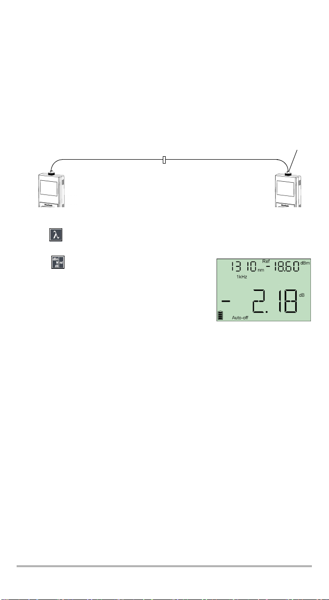
将功率计与光源相参考
在参考模式下,由于已从测得的功率中减去参考值,设备只显示被测光纤产生的损
耗。
注意: 必须为每个波长分别设置参考值。
若要手动将功率计与光源相参考:
1. 使用正确的适配器,将光源 (如 ELS-50)连接到功率计的检测器端口。
测试跳线
穿墙式连接器
参考值
测试跳线
适配器参考值
光源
功率计
2. 激活所需波长的光源。
3. 使用 匹配光源和功率计的波长。
波长显示在左上角。
4. 按住 几秒钟。功率计将当前检测到的功率存储
为新的参考功率值。
参考功率值显示在右上角 (dBm),当前损耗读数自动
切换到 dB。
5. 对于想要参考的每个波长,请重复此步骤。
注意: 对所需的所有波长完成参考后,请不要从光源端口断开参考测试跳线,直
到所有测试完成。
EPM-50/ELS-50 9
Page 82

测量功率或损耗 (EPM-50) 10
测量功率或损耗
除参考步骤外,测量绝对功率值的方法与功率计和光源相参考一样。
若要执行功率或损耗测量:
1. 根据需要,执行偏移归零 (请参阅电偏移归零 所在页面为 8)。
2. 正确检查和清洁光纤以获得最佳性能 (请参阅清洁和连接光纤 所在页面为 7)。
3. 对于损耗测量,将功率计与光源相参考 (请参阅将功率计与光源相参考 所在页面
为 9),然后禁用光源。
4. 使用正确的适配器和测试跳线,将被测光纤连接到光源 (如 ELS-50)和设备的检
测器端口。
注意: 如果已将功率计与光源相参考,只需将被测光纤连接到用于参考的测试跳
线。
适配器
测试跳线 测试跳线
穿墙式连接器 穿墙式连接器
光源
被测光纤
功率计
Page 83
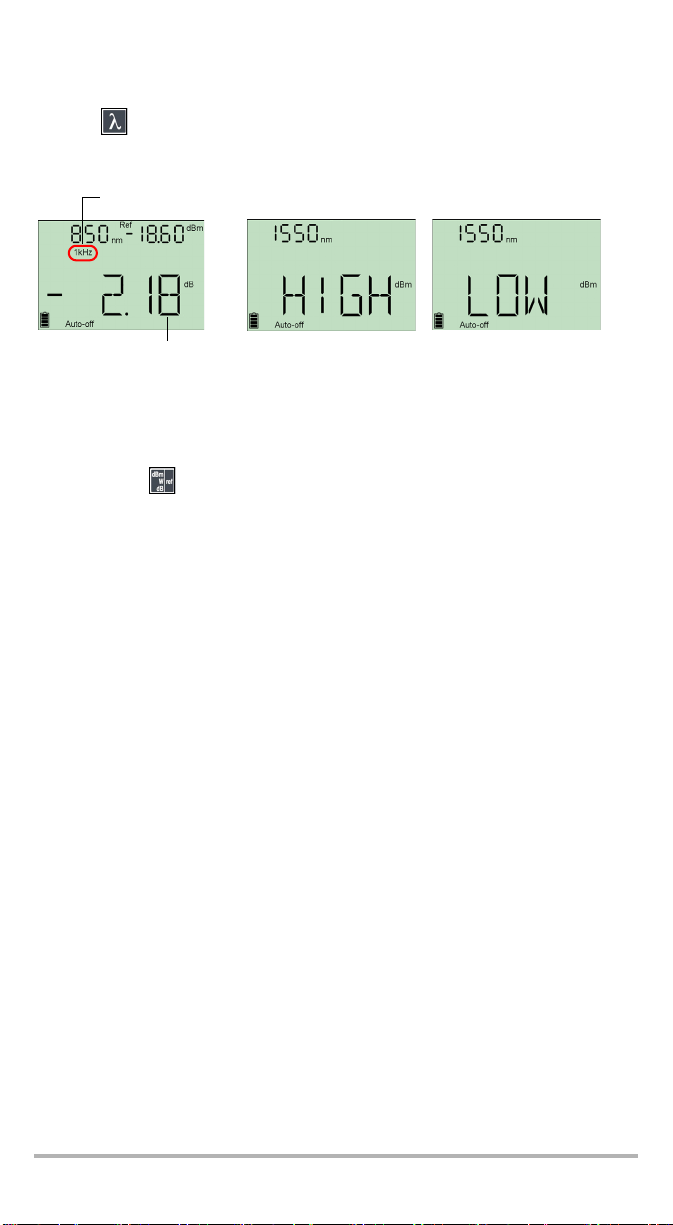
5. 激活所需波长的光源。
6. 使用 匹配光源和功率计的波长。
检测到的调制
被测光纤的实际功率
或损耗
功率或损耗超出功率范围时
技术规格 所在页面为 27)
(请参阅
设备检测到调制信号时显示调制值以及平均测量功率或损耗 (请参见左上图)。
您可能会注意到最后一个数字略不稳定。
7. 必要时,按 更改显示单位。
8. 对于其他波长,重复此过程。
EPM-50/ELS-50 11
Page 84

使用光源 (ELS-50) 12
5 使用光源 (ELS-50)
ELS-50 最多可包含三个光源。
激活 / 禁用光源
一次只能激活一个光源。没有使用光源时,设备显示 “ OFF” ,左上角显示为空。
若要激活光源和更改波长:
按 依次激活每个可用的光源。设备显示波长和调制。
若要禁用光源:
³ 按 ,直到经过最后一个光源。
或者
³ 按住 几秒钟。
调制光源信号
激活第一个光源时,信号始终为 CW (未调制)。切换光源时,调制保持不变。调制
指示在左上角。
可用的调制值有:CW、 270 Hz、 1kHz 和 2kHz。
若要更改信号调制:
1. 激活光源。
2. 按 在可用的调制间切换。
注意: 如果输出信号经过调制 (270Hz、 1kHz、
2kHz),您会注意到显示屏左上角有 “ out”
在闪烁。
Page 85

6 维护
本产品不包含需要用户维修的零件。但是,其中包含敏感的电子和光学器件,应轻拿
轻放,并在不用时将其存放在仪器箱中。
若要确保长期准确无误地执行操作:
³ 使用前始终检查光纤连接器,如有必要,则对其进行清洁。
³ 避免设备沾染灰尘。
³ 请用略微蘸水的布清洁设备外壳和前面板。
³ 将设备存放在室温下清洁干燥的地方。避免阳光直射设备。
³ 避免湿度过高或显著的温度变化。
³ 避免不必要的撞击和振动。
³ 如果设备中溅入或进入任何液体,请立即关闭电源、断开所有外部电源、取出电
池并让设备完全干燥。
警告
如果不按照此处指定的控制、调节方法和步骤进行操作和维护,可能导致
危险的辐射暴露。
EPM-50/ELS-50 13
Page 86

维护 14
清洁 EUI 连接器
定期清洁 EUI 连接器将有助于保持最佳性能。清洁时无需拆卸设备。
重要提示
如果内部连接器出现任何损坏,则必须打开模块外壳并重新校准。
要清洁 EUI 连接器:
1. 从仪器上取下 EUI,露出连接器底座和插芯。
转动
推入
2. 用一滴异丙醇润湿 2.5 mm 清洁棒 (如果酒精使用过量将留下痕迹)。
3. 轻轻将清洁棒插入 EUI 适配器,直到从另一端伸出为止 (顺时针方向缓慢旋转有
利于清洁)。
拉出
3
4
5
4. 轻轻转动清洁棒一圈,然后在抽出时继续转动。
Page 87

5. 用一个干燥的清洁棒重复步骤 3 到 4。
注意: 确保不要碰到清洁棒柔软的末端。
6. 按以下步骤清洁连接器端口内的插芯:
6a. 在不起毛的擦拭巾上滴一滴异丙醇酒精。
重要提示
因为异丙醇不绝对纯净,如果大量使用或任其蒸发 (大约 10 秒钟),则可
能会留下残余物。
避免瓶口和擦拭巾接触,并使表面快速干燥,而且要使用一次只倒出一滴
酒精的瓶子。
6b. 轻轻擦拭连接器和插芯。
6c. 用一块干燥的不起毛擦拭巾轻轻擦拭同一表面,确保连接器和插芯完全干
燥。
6d. 使用便携式光纤显微镜 (如 EXFO 的 FOMS)或光纤检测探头(如 EXFO 的
FIP)检验连接器表面。
警告
在设备工作时检验连接器的表面,将会对眼睛造成永久性伤害。
7. 将 EUI 装回仪器 (推入并顺时针旋转)。
8. 清洁棒和擦拭巾使用一次后丢弃。
EPM-50/ELS-50 15
Page 88

维护 16
清洁固定连接器
定期清洁连接器将有助于保持最佳性能。不要尝试拆卸设备。这样会损坏连接器。
清洁固定连接器:
1. 将一块不起毛的抹布折叠成正方形。
2. 只用一滴异丙醇酒精润湿不起毛擦拭巾的中心。
重要提示
酒精使用过量将留下痕迹。避免瓶口和抹布接触,并且不要使用一次倒出
太多酒精的瓶子。
3. 用抹布折叠且潮湿的部分,轻轻擦拭连接器螺纹三次。
重要提示
异丙醇酒精的蒸发大约需要十秒钟。由于异丙醇酒精不是绝对纯净,蒸发
后会留下极微的残余物。请确保在蒸发前干燥表面。
4. 用干燥的不起毛抹布轻轻擦拭同一表面三次,擦拭时使用旋转运动方式。
5. 抹布使用一次后丢弃。
6. 只用一滴异丙醇润湿清洁棒 (2.5 mm)。
重要提示
酒精使用过量将留下痕迹。避免瓶口与清洁棒接触,并且不要使用一次倒
出太多酒精的瓶子。
7. 将清洁棒缓慢插入连接器中,直到接触内部的插针 (顺时针方向缓慢旋转有利于
清洁)。
7
8
9
8. 将清洁棒轻轻转动一圈。
9. 在抽出清洁棒时仍保持转动。
10. 重复步骤 7 到 9,但这次使用干燥的清洁棒 (EXFO 提供的 2.5 mm 棒)。
注意: 确保不要碰到清洁棒的柔软末端,然后检查该棉棒是否清洁。
11. 清洁棒使用一次后应丢弃。
Page 89

清洁检测器端口
定期清洁检测器将有助于保持测量精度。
重要提示
设备不使用时,应始终用保护盖盖好检测器。
要清洁检测器端口:
1. 从检测器上取下保护盖和适配器 (FOA)。
2. 如果检测器上有灰尘,请用压缩空气吹除。
3. 切勿触摸棉签的柔软末端,只用一滴异丙醇酒精润湿清洁棒。
重要提示
酒精使用过量将留下痕迹。不要使用一次倒出太多酒精的瓶子。
4. 轻微用力 (避免打破检测器窗口),在检测器窗口上轻轻地旋转清洁棒。
5. 重复步骤 4,使用干燥的清洁棒或用压缩空气吹干。
6. 清洁棒使用一次后应丢弃。
EPM-50/ELS-50 17
Page 90

维护 18
更换电池
您的设备需要三节 AA 碱性电池或可充电电池。
若要更换电池:
1. 关闭设备。
2. 打开设备背面的电池盒盖。
3. 按所示极性更换电池。
4. 合上电池盒盖。
警告
切勿将电池投入火中或水中,也不要将电池的电极短路。禁止拆卸。
重新校准设备
制造和服务中心根据 ISO/IEC 17025 标准进行校准,该标准规定校准文档不能推荐校
准间隔时间,除非事先已经与客户达成协议。
规格的有效性取决于操作条件。例如,根据使用强度、环境条件和设备维护,校准的
有效性可以延长或缩短。应根据精度要求,为设备确定适当的校准间隔。
正常使用情况下, EXFO 建议每年重新校准一次设备。
注意: FlexCare 保修项目包括 “ 校准 / 验证” 软件包 (请参阅服务和维修 所在
注意: 重新校准仅适用于 EPM-50 功率计。
页面为 25)。
Page 91

产品的回收和处理 (仅适用于欧盟)
请根据当地条例之规定,正确回收或处理产品 (包括电气
和电子附件)。请勿将其丢弃到普通废物箱内。
本设备于 2005 年 8 月 13 日之后售出 (根据黑色方框判
别)。
³ 除非 EXFO 与客户、经销商或商业伙伴达成的单独协议中另有声明,否则 EXFO
将根据关于指令 2002/96/EC 的法律,对 2005 年 8 月 13 日以后进入欧盟成员国的
电子设备,承担与收集、处置、恢复和处理电子设备所产生的废弃物相关的费
用。
³ 除安全因素和环保利益外, EXFO 制造的设备 (使用 EXFO 品牌)其设计通常便
于拆卸和回收。
若要获得完整的回收 / 处理过程和联系信息,请访问 EXFO 网站:
www.exfo.com/recycle。
EPM-50/ELS-50 19
Page 92

故障排除 20
7 故障排除
解决常见问题
问题 可能原因 解决方案
设备无法启动。 电池电量已耗尽。 更换电池。
参考功率值与光源输出功率不同。接收到的功率超出检测器
的范围。
错误代码及描述
ER:按下一个键后,错误代码不再显示。
错误代码 描述 解决方案
LIGH
(仅 EPM-50)
3/11
7
13
偏移归零时检测到光。不
执行归零。
嵌入式软件故障。 联系 EXFO。
硬件故障。 更换设备。
非易失存储器损坏 (会出
现在设备初始化过程中)。
将保护盖正确装在检测器端口上,然
后重试。
³ 初始化过程中按住全部 3 个键重
³ 设备必须重新校准。联系
更改光源输出功率。
置设备。
EXFO。
Page 93

联系技术支持部
若要获得本产品的售后服务或技术支持,请用下列其中一个号码与 EXFO 联系。技术
支持部的工作时间为星期一至星期五,上午 8:00 至下午 7:00 (北美东部时间)。
有关技术支持的详细信息,请访问 EXFO 网站 www.exfo.com。
技术支持部
400 Godin Avenue
Quebec (Quebec) G1M 2K2
CANADA
为加快问题的处理过程,请将产品名称、序列号等信息 (见产品识别标签示例如
下),以及问题描述准备好后放在手边。
1 866 683-0155 (美国和加拿大)
电话:1 418 683-5498
传真:1 418 683-9224
support@exfo.com
P/N
**************** A
542392-3D
S/N
Made in Canada QST442B
2006 年 1 月
EPM-50XX
检测器
类型
Ver.
Mfg.
date
ELS-50-XX-XX-XX
也可能请求您提供嵌入式软件的版本号。
若要显示嵌入式软件的版本,生产日期和序列号:
1. 按住 并同时按 。设备即会显示嵌入的主软
件版本。
2. 再次按下 查看序列号和生产日期。
3. 按下 返回正常模式。
465 Godin Avenue
Vanier (Quebec) G1M 3G7 CANADA
端口
光源连接器光源
EPM-50/ELS-50 21
Page 94

故障排除 22
运输
运输设备时,应将温度维持在规格中所述的范围内。如果操作不当,可能会在运输过
程中损坏设备。建议遵循以下步骤,以将设备损坏的可能性降至最低:
³ 在运输时使用原有的包装材料包装设备。
³ 避免湿度过高或温度变化过大。
³ 避免阳光直接照射设备。
³ 避免不必要的撞击和振动。
Page 95

8 保修
一般信息
EXFO Electro-Optical Engineering Inc. (EXFO) 保证本设备从最初发货日起一年内,
对因材料或工艺所引起的缺陷实行保修。 EXFO 同时保证本设备在正常使用时将符合
适用的规范。
在保修期内, EXFO 将有权决定对于任何有问题需要维修的产品进行维修、更换或发
放信用卡。如果设备在保修期内被送回校准刻度,并且发现其符合所有已公布的规
范, EXFO 将会收取标准校准费用。
重要提示
如果发生以下情形,保修将无效:
³ 设备由未授权人员或非 EXFO 技术人员篡改、维修或更改。
³ 保修标签被撕掉。
³ 非本指南所指定的机箱螺丝被移走。
³ 未按本指南说明打开机箱。
³ 设备序列号已被修改、擦除或磨掉。
³ 本设备曾被不当使用、疏忽或意外被损坏。
本保修声明将取代以往所有其他明确表述、暗示或法定的保修声明,包括但不限于对
于适销性以及是否适合特定用途的暗示保修声明。在任何情况下, EXFO 均不承担特
殊事故、意外损坏或衍生性损坏的责任。
责任
EXFO 不对因使用产品造成的损坏负责,亦不对本产品所连任何其他设备的性能失
效,或本产品所关联之任何系统的操作失败负责。
EXFO 不对因不当使用或未经授权擅自修改本设备、附件及软件所造成的损坏负责。
EPM-50/ELS-50 23
Page 96

保修 24
免责
EXFO 保留随时更改其任一款产品设计或结构的权利,且不承担对用户所购买设备进
行更改的责任。各种附件,包括但不限于 EXFO 产品中使用的保险丝、指示灯、电池
和通用接口 (EUI) 等,不在此保修范围之内。
如果发生以下情形,保修将会无效:不正确的使用或安装、正常磨损和破裂、意外事
故、违规操作、疏忽、失火、水淹、闪电或其他自然事故、产品以外的原因或超出
EXFO 所能控制范围之外的其他原因。
重要提示
EXFO 对因使用不当或清洁方式不佳造成光学连接器损坏而进行的更换收取
费用。
合格证书
EXFO 保证本设备出厂装运时符合其公布的规格。
Page 97

服务和维修
EXFO 承诺:自购买之日起,对本设备提供五年的产品服务及维修。
若要发送任何设备进行技术服务或维修:
1. 请与其中一个 EXFO 授权客户服务中心联系 (请参阅 EXFO 全球服务中心 所在页
面为 26)。支持人员将确定您的设备是否需要检修、修理或校准。
2. 如果设备必须送回 EXFO 或授权服务中心,服务人员将签发返修货物授权 (RMA)
编号并提供返修地址。
3. 如有可能,请在设备送修之前,备份您的数据。
4. 请使用原始包装材料包装设备。请务必附上一份说明或报告,详细注明故障以及
发生故障的条件。
5. 将设备 (预付费)送回服务人员提供的地址。确认已将 RMA 号码填写在了货单
上。 EXFO 将拒收并退回无 RMA 号码的任何包裹。
注意: 返修的设备经测试之后,如果发现完全符合各种技术指标,则会收取测试
修复之后,我们会将设备寄回并附上一份维修报告。如果设备不在保修范围内,用户
应支付维修报告上所注明的费用。如果属于保修范围, EXFO 将支付设备的返程运
费。用户支付运输保险费。
常规重新校准不包括在任何保修计划内。由于基本或扩展的保修不包括校准 / 验证,
因此可选择购买定期的 FlexCare 校准 / 验证软件包。请与授权服务中心联系 (请参阅
EXFO 全球服务中心 所在页面为 26)。
设置费。
EPM-50/ELS-50 25
Page 98

保修 26
EXFO 全球服务中心
如果您的产品需要维修,请联系最近的授权服务中心。
EXFO 总部服务中心
400 Godin Avenue
Vanier (Quebec) G1M 2K2
CANADA
EXFO 欧洲服务中心
Omega Enterprise Park, Electron Way
Chandlers Ford, Hampshire S053 4SE
ENGLAND
爱斯福电讯设备 (深圳)有限公司
中国深圳市宝安区西乡街道 107 国道
愉盛工业区 (固戍路口边) 467 号,
10 栋 3 楼, 518126
1 866 683-0155 (美国和加拿大)
电话:1 418 683-5498
传真:1 418 683-9224
quebec.service@exfo.com
电话:+44 2380 246810
传真:+44 2380 246801
europe.service@exfo.com
电话:+86 (755) 2955 3100
传真:+86 (755) 2955 3101
beijing.service@exfo.com
Page 99

A 技术规格
OPTIONAL ACCESSORIES
PMA-22 (FC connector adapter for EPM-50 power meter)
PMA-32 (ST connector adapter for EPM-50 power meter)
PMA-54 (SC connector adapter for EPM-50 power meter)
STANDARD ACCESSORIES
Soft pouch, PMA-22 FC connector adapter, quick reference sticker in five languages,
Certificate of Calibration, Certificate of Compliance, three AA batteries
GENERAL SPECIFICATIONS
Size (H x W x D)
189 mm x 78 mm x 37 mm (7 7/16 in x 3 1/16 in x 1 7/16 in)
Weight
0.4 kg (0.9 lb)
Temperature operating
—10 °C to 50 °C (14 °F to 122 °F)
storage
—40 °C to 70 °C (–40 °F to 158 °F)
Relative humidity
0 % to 95 % non-condensing
SPECIFICATIONS
a
MODEL EPM-53 EPM-53X
Power meter port
InGaAs InGaAsX
Power range b (dBm)
10 to –60 26 to –50
Number of calibrated wavelengths
c
55
Power uncertainty
d
±5 % ±5 %
Resolution (dB)
0.01 0.01
Display units
dB/dBm/W dB/dBm/W
Tone detection (Hz)
270, 1 k, 2 k 270, 1 k, 2 k
Battery life (hours)
d
>300 >300
Warranty (year)
11
下列技术规格如有更改,恕不另行通知。本节所述信息仅供参考。要获得
本产品的最新技术规格,请访问 EXFO 网站 www.exfo.com。
EPM-50
重要提示
Notes
a. All specifications valid at 23 °C ± 3 °C, with an FC/UPC connector
b. In CW mode
c. Wavelengths: 850 nm, 1300 nm, 1310 nm, 1490 nm, 1550 nm
d. Typical
EPM-50/ELS-50 27
Page 100

技术规格 28
SPECIFICATIONS
b
b, c
b, d
b
Tone generation (Hz)
Warranty (year)
STANDARD ACCESSORIES
Soft pouch, LSA-89 FC connector adapter, quick reference sticker in five languages,
Certificate of Compliance, three AA batteries
GENERAL SPECIFICATIONS
Size (H x W x D)
189 mm x 78 mm x 37 mm (7 7/16 in x 3 1/16 in x 1 7/16 in)
Weight
0.4 kg (0.9 lb)
Temperature operating
storage
—10 °C to 50 °C (14 °F to 122 °F)
—40 °C to 70 °C (–40 °F to 158 °F)
Relative humidity
0 % to 95 % non-condensing
OPTIONAL ACCESSORIES
LSA-89 (FC connector adapter for ELS-50 Light Source)
LSA-90 (ST connector adapter for ELS-50 Light Source)
LSA-91 (SC connector adapter for ELS-50 Light Source)
Manual (User guide)
ELS-50
Notes
a. All specifications valid at 23 °C ± 3 °C, with an FC/UPC connector
b. Typical
c. rms for lasers and —3 dB width for LEDs
d. After 15 minutes warmup; expressed as ± half the difference between the maximum and minimum values measured
over 8 hours
 Loading...