

Page 1
POWER METER/LIGHT SOURCE/
NETWORK TESTING
OPTICAL LOSS TEST SET
EPM-500/ELS-500/EOT-500
USER GUIDE
Page 2

Copyright © 2006 EXFO Electro-Optical Engineering Inc. All rights reserved. No part
of this publication may be reproduced, stored in a retrieval system or transmitted in
any form, be it electronically, mechanically, or by any other means such as
photocopying, recording or otherwise, without the prior written permission of EXFO
Electro-Optical Engineering Inc. (EXFO).
Information provided by EXFO is believed to be accurate and reliable. However, no
responsibility is assumed by EXFO for its use nor for any infringements of patents or
other rights of third parties that may result from its use. No license is granted by
implication or otherwise under any patent rights of EXFO.
EXFO’s Commerce And Government Entities (CAGE) code under the North Atlantic
Treaty Organization (NATO) is 0L8C3.
The information contained in this publication is subject to change without notice.
Trademarks
EXFO’s trademarks have been identified as such. However, the presence or
absence of such identification does not affect the legal status of any trademark.
Units of Measurement
Units of measurement in this publication conform to SI standards and practices.
Patents
EXFO’s Universal Interface is protected by US patent 6,612,750.
ii
Page 3

Contents
Certification Information .................................................................................. v
1 Introducing the EPM-500/ELS-500/EOT-500 .............................. 1
Main Features ................................................................................................... 1
Power Sources .................................................................................................. 3
Typical Applications .......................................................................................... 3
Conventions ...................................................................................................... 3
2 Safety Information ................................................................... 4
Electrical Safety Information ............................................................................. 4
Laser Safety Information (ELS-500 and EOT-500 without VFL) .......................... 4
Laser Safety Information (Units with VFL) ......................................................... 5
3 Getting Started ......................................................................... 6
Turning the Unit On and Off ............................................................................. 6
Activating Automatic Shutdown (Auto-Off) ...................................................... 6
Activating the Backlight .................................................................................... 7
Accessing and Navigating Setup Menus ........................................................... 7
Installing the EXFO Universal Interface (EUI) ..................................................... 8
Cleaning and Connecting Optical Fibers ........................................................... 9
4 Measuring Power or Loss (EPM-500 and EOT-500) ................ 10
Nulling Electrical Offsets ................................................................................. 10
Referencing Your Power Meter to a Source ..................................................... 11
Measuring Power or Loss ................................................................................ 12
Automatically Detecting Wavelength .............................................................. 14
Setting Pass/Fail Thresholds ............................................................................ 15
5 Using a Light Source (ELS-500 and EOT-500) or VFL .............. 16
Activating/Deactivating a Light Source or VFL ................................................. 16
Modulating the Source Signal ........................................................................ 17
Using Auto-Switching Mode ........................................................................... 17
Sending Source Power Value with Signal ........................................................ 18
6 Saving and Recalling Power/Loss Values ............................... 20
Setting Autonaming Scheme .......................................................................... 20
Saving, Recalling and Deleting Data ............................................................... 21
Transferring Data to a Computer .................................................................... 23
7 Maintenance ............................................................................ 24
Cleaning EUI Connectors ................................................................................ 25
Cleaning Detector Ports .................................................................................. 27
Recharging the Battery ................................................................................... 27
Replacing Battery ............................................................................................ 28
Recalibrating the Unit ..................................................................................... 28
Recycling and Disposal (Applies to European Union Only) .............................. 29
EPM-500/ELS-500/EOT-500 iii
Page 4

Contents iv
8 Troubleshooting ...................................................................... 30
Solving Common Problems ............................................................................. 30
Reverting Unit to Factory Settings .................................................................. 31
Error Codes and Descriptions .......................................................................... 31
Contacting the Technical Support Group ........................................................ 32
Finding Information on the EXFO Web Site .................................................... 33
Transportation ................................................................................................ 33
9 Warranty .................................................................................. 34
General Information ....................................................................................... 34
Liability ........................................................................................................... 34
Exclusions ....................................................................................................... 35
Certification .................................................................................................... 35
Service and Repairs ......................................................................................... 36
EXFO Service Centers Worldwide .................................................................... 37
A Technical Specifications .......................................................... 38
Page 5

Certification Information
F.C.C. Information
Electronic test equipment is exempt from Part 15 compliance (FCC) in the United
States. However, compliance verification tests are systematically performed on
most EXFO equipment.
Information
Electronic test equipment is subject to the EMC Directive in the European Union.
The EN61326 standard prescribes both emission and immunity requirements for
laboratory, measurement, and control equipment. This unit has undergone
extensive testing according to the European Union Directive and Standards.
DECLARATION OF CONFORMITY
Application of Council Directive(s): 73/23/EEC - The Low Voltage Directive
Manufacturer’s Name: EXFO ELECTRO-OPTICAL ENG.
Manufacturer’s Address: 400 Godin Avenue
Equipment Type/Environment: Industrial Scientific Equipment
Trade Name/Model No.: EPM-500 Power Meter, ELS-500 Light Source,
Standard(s) to which Conformity is Declared:
EN 60825-1: 1994/
A2: 2001
EN 61326: 1997/ A2:
2001
EN 55022: 1998/ A1:
2000
I, the undersigned, hereby declare that the equipment specified above conforms to the above Directive and Standards.
Manufacturer
Signature:
Full Name: Stephen Bull, E. Eng
Position: Vice-President Research and
Address: 400 Godin Avenue Vanier, Quebec,
Date: December 22, 2004
Safety of Laser Products-Part 1: Equipment Classification, Requirement, and
User’s guide
Electrical Equipment for Measurement, Control and Laboratory
Use - EMC Requirements
Limits and methods of measurement of radio disturbance characteristics of
information technology equipment
Development
Canada
89/336/EEC - The EMC Directive
Vanier, Québec
Canada G1M 2K2
(418) 683-0211
EOT-500 OLTS
EPM-500/ELS-500/EOT-500 v
Page 6

Introducing the EPM-500/ELS-500/EOT-500 1
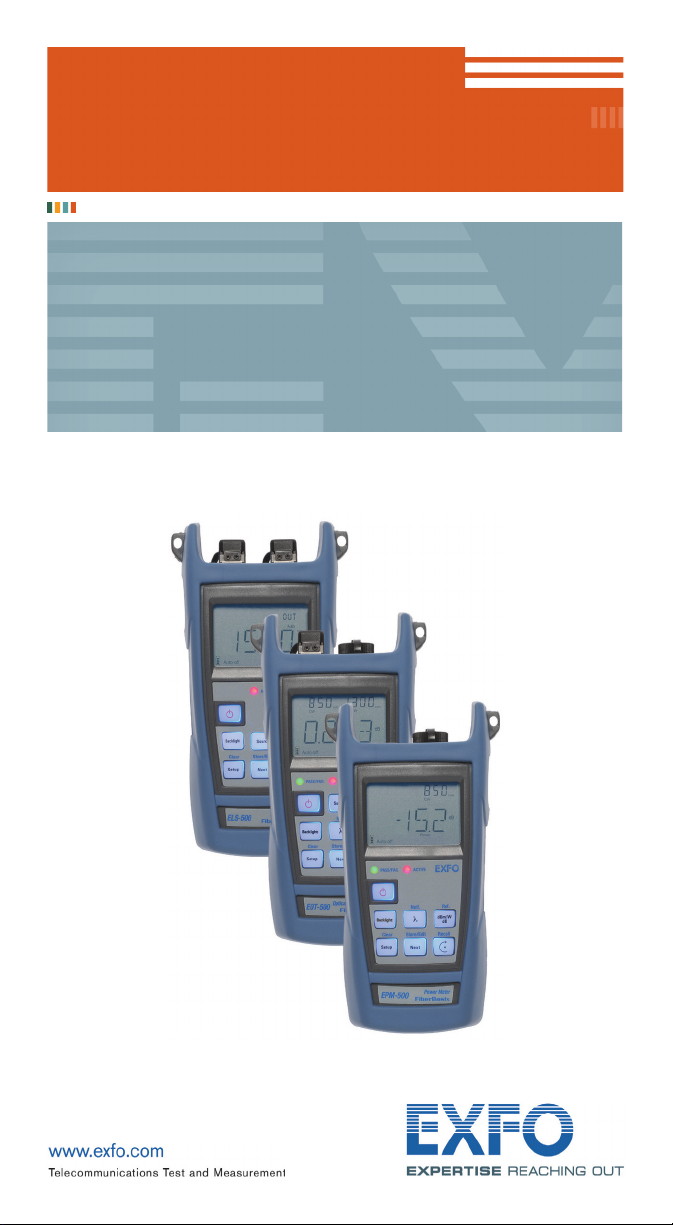
1 Introducing the
EPM-500/ELS-500/EOT-500
This user guide covers the following products (unless otherwise specified,
descriptions apply to all):
³ EPM-500 Power Meter
³ ELS-500 Light Source
³ EOT-500 Optical Loss Test Set: combines both a power meter and a light source
Main Features
EPM ELS EOT
Ge or GeX detector with 6 calibrated wavelengths X X
Absolute power and link loss measurements X X
Automatic wavelength detection X X
No offset nulling of detectors required in normal operation X X
Multiple source configurations on a single port [EOT-500] or
on one or two ports [ELS-500]
Optional visual fault locator X X X
Transmission of editable power value with source’s signal for
automatic reference with compatible power meter
Transmission of wavelength to compatible power meter in
automatic wavelength or auto-switching mode
Modulated signal emission or detection (270 Hz, 1 kHz and
2 kHz) compatible with other EXFO units
Data storage on unit and USB transfer to a computer X X
User-configurable pass/fail thresholds with LED indicator X X
Automatic shutdown after 10 minutes of idle time (auto-off) X X X
XX
XX
XX
XXX
Page 7
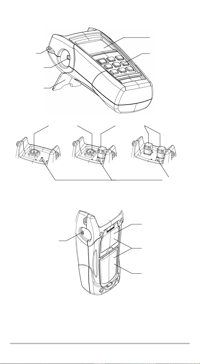
LCD display
Shoulder
strap eyelet
DC connector
Stand
Power meter
detector port
USB connector
Keypad
(EOT-500 shown)
Light source
ports
EOT-500 ELS-500EPM-500
Visual fault
locator port
Safety label
and serial number
(under the stand)
Quick reference labels
Battery compartment
EPM-500/ELS-500/EOT-500 2
Page 8

Introducing the EPM-500/ELS-500/EOT-500 3
Power Sources
The units operate with the following power sources:
³ AC adapter (connected to standard power outlet—indoor use only)
Compatible car outlet adapter available upon request.
³ Li-Ion rechargeable battery (automatically takes over if you unplug the
AC adapter)
IMPORTANT
If the battery level becomes too low, the unit turns itself off.
Typical Applications
³ Transmitter power measurements (dBm and W)
³ Fiber-link loss testing (dB)
³ Component insertion-loss testing (dB)
³ Fiber identification with 270-Hz, 1-kHz and 2-kHz signals
³ Fiber installation and maintenance applications
³ FTTx: testing of passive optical networks (PONs)
Conventions
Before using the product described in this manual, you should understand the
following conventions:
WARNING
Indicates a potentially hazardous situation which, if not avoided,
could result in death or serious injury. Do not proceed unless you
understand and meet the required conditions.
CAUTION
Indicates a potentially hazardous situation which, if not avoided,
may result in minor or moderate injury. Do not proceed unless you
understand and meet the required conditions.
CAUTION
Indicates a potentially hazardous situation which, if not avoided,
may result in component damage. Do not proceed unless you
understand and meet the required conditions.
IMPORTANT
Refers to information about this product you should not overlook.
Page 9

2 Safety Information
Electrical Safety Information
WARNING
Use the AC adapter provided with this product
indoors only.
Laser Safety Information (ELS-500 and EOT-500 without VFL)
WARNING
Do not install or terminate fibers while a laser source is active. Never
look directly into a live fiber and ensure that your eyes are protected
at all times.
WARNING
Use of controls, adjustments and procedures for operation and
maintenance other than those specified herein may result in
hazardous radiation exposure.
Your instrument is a Class 1M laser product in compliance with standards
IEC 60825-1 Amendment 2: 2001 and 21 CFR 1040.10. Invisible laser radiation may
be encountered at the output port.
The product is safe under reasonably foreseeable conditions of operation but it may
be hazardous if you use optics within a diverging or collimated beam. Do not view
directly with optical instruments.
Note: Label shown for information purposes only. It is not affixed to your
product.
Note: Units without VCSEL sources are Class 1 products.
EPM-500/ELS-500/EOT-500 4
Page 10

Safety Information 5
Laser Safety Information (Units with VFL)
Your instrument is a Class 3R laser product in compliance with standards
IEC 60825-1 Amendment 2: 2001 and 21 CFR 1040.10. It is potentially harmful in
direct intrabeam viewing.
The following label(s) indicate that the product contains a Class 3R source:
If VFL option is available
IEC 60825-1:1993+A2:2001
21 CFR 1040.10
LASER RADIATION
AVOID DIRECT EYE EXPOSURE
CLASS 3R LASER PRODUCT
λ: 650 ±10 nm
P
maximum < 5mW (into free space)
out
VFL LASER APERTURE
Affixed to back
(under the stand)
Indicated on
connector panel
Page 11
3 Getting Started
Turning the Unit On and Off
When you turn off the EPM-500 or the EOT-500, it saves the current wavelength, unit
and reference power.
IMPORTANT
If you remove batteries (and the AC adapter is unplugged), the unit
will turn off without saving the above values.
If batteries are low (and the AC adapter is unplugged), the unit will
save the above values and turn off.
Note: Offset nulling values are always returned to factory settings.
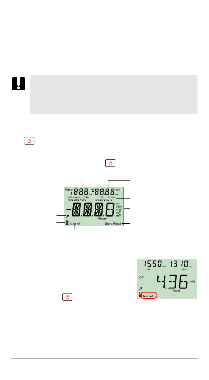
To turn on the unit:
Press . The unit displays EXFO for a few seconds. You may use it immediately
under normal conditions.
To turn off the unit:
From normal operating mode, hold down a few seconds.
Source wavelength (EOT)
Batteries in use
Fiber number
AC adapter
plugged in
(with level)
Auto-off activated
Display
Data storage or recall modes
Power meter wavelength or
reference power (EPM/EOT)
Modulation values
Measured power/loss (EPM/EOT)
Active source wavelength (ELS)
Activating Automatic Shutdown (Auto-Off)
When auto-off is activated, the unit will turn off after
10 minutes of idle time.
Auto-off is activated by default when you turn on the
unit.
To deactivate/reactivate auto-off:
When unit is on, press .
EPM-500/ELS-500/EOT-500 6
Page 12
Getting Started 7
Activating the Backlight
When operating the unit in the dark, use the backlight to make data on the display
more visible. The keypad buttons will also lighten for about 10 seconds.
Note: When backlight is activated, you must always press a button once to
lighten the keypad, then press the actual button you want.
To activate/deactivate the backlight:
From normal operating mode, press .
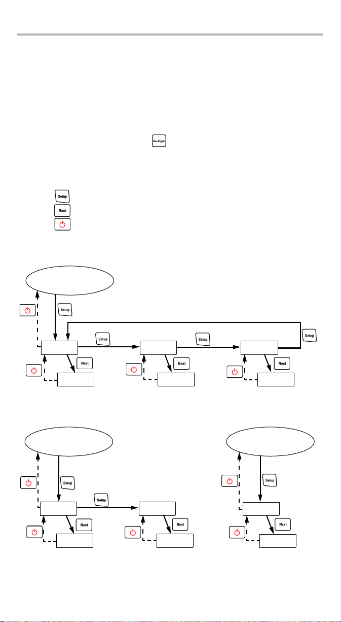
Accessing and Navigating Setup Menus
Setup menus differ in each model. You may access and navigate menus as follows:
³ Press repeatedly to switch between options in a menu level.
³ Press once to access a submenu from the main level.
³ Press to exit menus (one level at a time).
Note: Details about each menu option are given in this user guide.
EOT-500
Normal Mode
PM DATA SRC
P/F CAB 1
*
PREF
*: Default cable name
EPM-500 ELS-500
Normal Mode
PM DATA
P/F CAB 1
*: Default cable name
Normal Mode
SRC
*
PREF
Page 13

Installing the EXFO Universal Interface (EUI)
The EUI fixed baseplate is available for connectors with angled (APC) or non-angled
(UPC) polishing. A green border around the baseplate indicates that it is for
APC-type connectors, as shown below:
Green border
indicates APC
option
To install an EUI connector adapter onto the EUI baseplate:
1. Hold the EUI connector adapter so the dust cap opens downwards.
indicates UPC option
Bare metal
(or blue border)
3
4
2
2. Close the dust cap in order to hold the connector adapter more firmly.
3. Insert the connector adapter into the baseplate.
4. While pushing firmly, turn the connector adapter clockwise on the baseplate to
lock it in place.
EPM-500/ELS-500/EOT-500 8
Page 14

Getting Started 9
Cleaning and Connecting Optical Fibers
IMPORTANT
To ensure maximum power and to avoid erroneous readings:
³ Always clean fiber ends as explained below before inserting
them into the port. EXFO is not responsible for damage or errors
caused by bad fiber cleaning or handling.
³ Ensure that your patchcord has appropriate connectors. Joining
mismatched connectors will damage the ferrules.
To connect the fiber-optic cable to the port:
1. Clean the fiber ends as follows:
1a. Gently wipe the fiber end with a lint-free swab dipped in isopropyl alcohol.
1b. Use compressed air to dry completely.
1c. Visually inspect the fiber end to ensure its cleanliness.
2. Carefully align the connector and port to prevent the fiber end from touching the
outside of the port or rubbing against other surfaces. If your connector features
a key, ensure that it is fully fitted into the port’s corresponding notch.
3. Push the connector in so that the fiber-optic cable is firmly in place, thus
ensuring adequate contact.
If your connector features a screwsleeve, tighten the connector enough to firmly
maintain the fiber in place. Do not overtighten, as this will damage the fiber and
the port.
Note: If your fiber-optic cable is not properly aligned and/or connected, you
will notice heavy loss and reflection.
Page 15

4 Measuring Power or Loss
(EPM-500 and EOT-500)
Nulling Electrical Offsets
Temperature and humidity variations affect the performance of electronic circuits
and optical detectors. Nulling the electrical offsets eliminates these effects. Your unit
has been designed not to require offset nulling under normal operation, but you
should perform it whenever environmental conditions change significantly or when
measuring very low power values.
IMPORTANT
If light reaches the detector when nulling offsets, LIGH appears on
the display and the nulling is not performed. You will need to press a
key to return to the previous display.
Note: Factory-defined values will be reinstated when you turn off the unit.
To perform an offset nulling:
Hold down a few seconds. The unit displays NULL
while nulling the offsets, then returns to normal mode.
Note: Keypad is disabled during the operation.
EPM-500/ELS-500/EOT-500 10
Page 16

Measuring Power or Loss (EPM-500 and EOT-500) 11
Referencing Your Power Meter to a Source
In reference mode, your unit displays the loss created by the fiber under test only,
since a reference value is subtracted from the measured power.
Note: You must set a reference value separately for each wavelength.
Compatible sources (such as EOT-500 and ELS-500) can transmit a power value to
your power meter, avoiding the need for manual referencing.
IMPORTANT
The value sent is not the source’s actual power. It is a user-defined
value that may not take the optical link’s loss into account.
To receive the reference power value from a compatible source:
1. Connect a compatible source to your power meter
(as shown below, with or without a fiber under
test).
2. Use the source to emit the signal that contains its
power value (see Sending Source Power Value
with Signal on page 18).
³ If reference value or units change, the power
meter beeps.
³ The new reference power is displayed in the top right corner (in dBm) and
current loss reading is automatically switched to dB.
Note: When using this feature, you cannot change the power meter’s
wavelength manually. The power meter behavior is totally determined
by the source.
To reference the power meter to a source manually:
1. Using the proper adapter, connect a light source (such as ELS-500 or EOT-500)
to the detector port of your power meter.
test jumper
Bulkhead
connector
Light
source
2. Activate the source at the desired wavelength.
Reference
test jumper
Power
meter
AdapterReference
Page 17

3. Match the source and power meter wavelengths:
³ If the source emits an auto-wavelength signal
or is in auto-switching mode (see
Automatically Detecting Wavelength on
page 14 and Using Auto-Switching Mode on
page 17), the power meter automatically
matches the source wavelength.
³ Press to switch between calibrated wavelengths.
4. Hold down a few seconds. The power meter
stores the currently detected power as the new
reference power.
Reference power is displayed in the top right
corner (in dBm) and current loss reading is
automatically switched to dB.
5. Repeat the procedure for each wavelength you
want to reference (if you use auto-switching mode, the power meter
automatically references wavelengths one at a time).
Note: When using dB units, press to display the current wavelength for a
few seconds. To change this wavelength, press again while it is
displayed.
Measuring Power or Loss
Measuring absolute power or link loss is done the same way, except for the
referencing step.
To perform power or loss measurements:
1. If necessary, perform an offset nulling (see Nulling Electrical Offsets on page 10).
2. Check and clean your fibers appropriately for optimum performance
(see Cleaning and Connecting Optical Fibers on page 9).
3. For loss measurements, reference your power meter to a light source
(see Referencing Your Power Meter to a Source on page 11), then deactivate the
light source.
EPM-500/ELS-500/EOT-500 12
Page 18

Measuring Power or Loss (EPM-500 and EOT-500) 13
4. Using the proper adapter and test jumpers, connect a fiber under test to a light
source (such as ELS-500 or EOT-500) and to the detector port of your unit.
Note: If you have referenced your power meter to a source, simply connect a
fiber under test to the test jumpers used for referencing.
Te st
jumper
Light
source
Bulkhead
connector
jumper
Bulkhead
connector
Fiber under test
Power
meter
Adapter
Te st
5. Activate the source at the desired wavelength.
6. Match the source and power meter wavelengths:
³ If the source emits an auto-wavelength signal
or is in auto-switching mode (see
Automatically Detecting Wavelength on
page 14 and see Using Auto-Switching Mode
on page 17), the power meter automatically
matches the source wavelength.
OR
³ Press to switch between calibrated wavelengths.
Modulation detected
Actual power or loss
of fiber under test
When power or loss is outside power limits
(see Technical Specifications on page 38)
When the unit detects a modulated signal, it beeps and displays the modulation
value and average measured power or loss (see left illustration above). You may
notice a slightly unstable last digit.
7. If necessary, change the displayed units by pressing .
8. Repeat the procedure for other wavelengths.
Page 19

Automatically Detecting Wavelength
Compatible sources (such as EOT-500 and ELS-500) can transmit their wavelength
value through the fiber, avoiding the need to manually match the source and power
meter wavelengths.
Note: When you receive an auto-wavelength signal or when the source is in
auto-switching mode, you cannot manually change the power meter
wavelength. The power meter behavior is totally determined by the
source.
To receive the auto-wavelength signal or detect the source's
auto-switching mode:
1. Connect a compatible source to your power meter.
2. Activate the source in Auto mode (EOT-500 and
ELS-500: see Modulating the Source Signal on
page 17) or in auto-switching mode (see Using
Auto-Switching Mode on page 17).
Your power meter automatically matches the
source wavelength. If the wavelengths differ, it also
beeps and returns you to normal operating mode.
EPM-500/ELS-500/EOT-500 14
Page 20

Measuring Power or Loss (EPM-500 and EOT-500) 15
Setting Pass/Fail Thresholds
You can define thresholds to specify acceptable power (dBm) or loss (dB) values for
each wavelength. Thresholds are often supplied by system manufacturers and
depend on the system deployed.
When a threshold is activated, the PASS/FAIL LED
is turned on. If it is green, the threshold
succeeded, if the PASS/FAIL LED is red, the
threshold failed.
To set pass/fail thresholds:
1. From normal operating mode, press
repeatedly until you reach PM.
2. Press to access the first submenu, then press
3. Press to switch between power (dBm) and
4. Press to switch between available wavelengths. An asterisk (*) appears
5. Press to activate/deactivate the displayed threshold. The PASS/FAIL LED
6. Edit the pass/fail threshold as follows:
7. Press twice to exit setup menus.
repeatedly until you reach the P/F menu.
loss (dB) values.
beside activated thresholds. If no threshold is set for a wavelength, the unit
indicates “----”.
will lighten (green or red) when you return to normal mode.
6a. Hold down a few seconds. The first digit of the threshold blinks.
6b. Clear all digits by holding down a few seconds.
AND/OR
Select a digit to change by holding until it blinks, then increase its
value by pressing (it returns to 0 after 9). After the last digit, all digits
blink: you may add/remove the “–” sign by pressing .
6c. While a digit blinks, hold down a few seconds to save the modified
value (it remains in memory even when you turn off the unit) or press
to return to the previous value without saving.
Page 21

5 Using a Light Source
(ELS-500 and EOT-500) or
VFL
The ELS-500 may contain up to three sources (one-port models) or up to four
sources (two-port models). The EOT-500 may contain up to three sources.
Note: The VFL option may also be present on the EPM-500.
Activating/Deactivating a Light Source or VFL
Only one source may be active at a time. When no source is active, the unit displays
OFF.
Source wavelength (and VFL indicator)
and modulation (when active)
EOT-500 ELS-500
To activate a light source (or VFL) and change the wavelength:
Press to activate each available source in turn, including the VFL. The unit
displays the wavelength and modulation.
To deactivate the light source:
Press until you get past the last source.
Active source
port
EPM-500/ELS-500/EOT-500 16
Page 22

Using a Light Source (ELS-500 and EOT-500) or VFL 17
Modulating the Source Signal
When you activate the first source (after turning on the unit), the signal is always
CW (unmodulated). When you switch sources, the modulation remains the same
(VFL remembers its own modulation). Modulation is indicated in the top left
(port #1) or top right (port #2) corner.
Available modulation values are: CW, Auto, auto-switching mode, 270 Hz, 1 kHz and
2kHz (VFL: CW and 1Hz only).
Note: Auto is a modulated signal detected by compatible units (see
Automatically Detecting Wavelength on page 14). It provides greater
autonomy than CW, but covers a reduced power range.
Note: Auto-switching mode is a special signal detected by compatible units
To change the signal modulation:
1. Activate the source.
2. Press to switch between available
(see Using Auto-Switching Mode on page 17).
modulations.
Using Auto-Switching Mode
In auto-switching mode, your source automatically
switches from one wavelength to another. The power
meter connected to this source displays the power
value for each wavelength one at a time. The
wavelength value appearing on the display changes
every two seconds.
To activate auto-switching mode:
1. Press to activate the source.
2. Press to switch between available modulations until the Auto indicator
blinks on your display.
Page 23

Sending Source Power Value with Signal
Your source can transmit a user-defined power value to compatible power meters
(such as EOT-500 and EPM-500) through the fiber. If the reference source is far from
the power meter, you can connect your source to the power meter to send the
reference value. With this feature you can also correct for power variations.
Note: If you connect a fiber between EOT-500’s source and detector ports, the
unit can use the actual source output power as reference power.
Note: For details about how compatible power meters receive this power
value, see Referencing Your Power Meter to a Source on page 11.
IMPORTANT
The value sent is not (and will not affect) the source’s actual power.
It is a user-defined value that may not take the optical link’s loss into
account.
To define the source power value to use as reference:
1. From normal operating mode, press repeatedly until you reach SRC.
2. Press to access the first submenu, then press repeatedly until you
reach the PREF menu.
3. Press to switch between available source wavelengths and select one. The
unit displays the currently defined power value for this wavelength.
4. Edit the power value as follows:
4a. Hold down a few seconds. The first digit of the power value blinks.
4b. Revert all digits to 0 by holding down a few seconds.
AND/OR
Select a digit to change by pressing until it blinks, then increase its
value by pressing (it returns to 0 after 9). After the last digit, all digits
blink: you may add/remove the “–” sign by pressing .
4c. While a digit blinks, hold down a few seconds to save the modified
value (it remains in memory even when you turn off the unit) or press
to return to the previous value without saving.
5. Press twice to exit setup menus.
EPM-500/ELS-500/EOT-500 18
Page 24

Using a Light Source (ELS-500 and EOT-500) or VFL 19
To use the actual source output power as reference (EOT-500 only):
1. Connect a fiber between the source and power meter of same unit.
2. Activate the source at the desired wavelength.
3. Match the source and power meter wavelengths:
³ If the source emits an auto-wavelength signal
or is in auto-switching mode (see
Automatically Detecting Wavelength on
page 14 and Using Auto-Switching Mode on
page 17), the power meter automatically
matches the source wavelength.
OR
³ Press to switch between calibrated wavelengths.
4. From normal operating mode, hold down and . The unit displays PREF
for a few seconds while saving the value, then returns to normal mode.
To send the source power value:
1. Activate the source.
2. Change the modulation signal to AUTO or auto-switching.
If you use auto-switching mode, the power value of each wavelength will
automatically be sent.
3. Hold down and to send the power value with an auto-wavelength
signal. The unit displays Send for a few seconds, then returns to normal mode.
Page 25

6 Saving and Recalling
Power/Loss Values
You can save 1000 power/loss values in your unit, along with references. You will
save and recall this data according to cable names and fiber numbers. To free up
memory, you can transfer saved data to a computer or simply delete all.
Setting Autonaming Scheme
When saving data, the unit suggests fiber IDs based on autonaming settings. After
saving a value, the unit prepares the next fiber ID according to the selected
increment (0, 1 or 2).
To define the cable name and the starting fiber ID and increment value:
1. From normal operating mode, press
repeatedly until you reach DATA.
2. Press to access CAB1 or the last cable name
edited.
3. Hold down until the first character of the cable
name blinks.
4. Select a character to change by pressing until it blinks, then increase its
value by pressing (it returns to 0 after Z).
5. While a digit blinks, hold down a few seconds to save the modified value
(it remains in memory even when you turn off the unit) or press to return
to the previous value without saving.
6. Press twice to exit setup menus.
EPM-500/ELS-500/EOT-500 20
Page 26

Saving and Recalling Power/Loss Values 21
Saving, Recalling and Deleting Data
IMPORTANT
³ You cannot recover deleted data. Ensure that you transfer your
data to a computer if you intend to use it later.
³ Deleting a single value does not free memory. To free memory,
you must delete all data at once.
To save a power/loss value:
1. If you want to view or change the fiber ID before
saving:
1a. From normal operating mode, press or
to view the fiber ID that will be used next.
1b. Change the fiber ID by using and to
move forward or backward in the list.
2. Hold down a few seconds to save the
measured value under the selected fiber ID.
To recall saved data:
1. From normal operating mode, hold down a
few seconds. The Recall indicator is displayed
with the cable name, then the last saved value and
its fiber ID.
2. When fiber ID is displayed, hold down a few
seconds to return to the cable name list. Select the
cable in which you want to recall saved data by
using and to move forward or backward. The last saved value in the
selected cable and its fiber ID will be displayed after 3 seconds.
3. View values you want by using and to move forward or backward in
saved data. You can also change the units by pressing .
4. Press to return to normal mode.
To delete a single saved value from the unit:
1. From normal operating mode, hold down a
few seconds. The Recall indicator is displayed
with the cable name, then the last saved value and
its fiber ID.
2. When fiber ID is displayed, hold down a few
seconds to return to the cable name list. Select the
cable in which you want to recall saved data by
using and to move forward or backward. The last saved value in the
selected cable and its fiber ID will be displayed after 3 seconds.
3. Select the value to delete by using and to move forward or backward
in saved data.
4. Hold down a few seconds. The unit displays “dEL”, then displays another
saved data.
5. Press to return to normal mode.
Page 27

To delete a cable name:
1. From normal operating mode, hold down a
few seconds. The Recall indicator is displayed
with the last cable name, then the last saved value
and its fiber ID.
2. When fiber ID is displayed, hold down a few
seconds to return to the cable name list, then,
select the cable you want to delete by using
and to move forward or backward.
3. Hold down a few seconds. The unit displays “dEL”, then displays another
cable name.
4. Press to return to normal mode.
To delete all saved data from the unit:
1. From normal operating mode, hold down a
few seconds.The Recall indicator is displayed with
the last cable name, then the last saved value and
its fiber ID.
2. When fiber ID is displayed, hold down both
and a few seconds. The unit displays “dEL”
and “ALL”, then automatically returns to normal
mode.
EPM-500/ELS-500/EOT-500 22
Page 28

Saving and Recalling Power/Loss Values 23
Transferring Data to a Computer
Using an appropriate USB cable and the Handheld Data Transfer software, you can
transfer saved data from your handheld unit to a computer. This way, you can
increase storage capacity, perform better analyses on your data and create reports.
IMPORTANT
Transferred data is not automatically deleted from your unit.
To transfer data to a computer:
1. Using a USB cable, connect your unit to an available USB port of the computer.
USB connector
USB port
2. Turn on both the computer and your handheld unit. Connect your unit to a
power outlet to ensure that your unit will remain on during the transfer.
3. On the computer, launch the Handheld Data Transfer application and start the
operation.
The unit displays “REM” and temporarily deactivates the keyboard and auto-off.
Note: For details about setting up the software and transferring data, refer to
the Handheld Data Transfer online help.
Page 29

7 Maintenance
This product contains no user-serviceable parts. However, it contains sensitive
electronic and optical components, and should be handled carefully and stored in
its carrying case when not in use.
To help ensure long, trouble-free operation:
³ Always clean fiber-optic connectors before using them.
³ Keep the unit free of dust.
³ Clean the unit casing and front panel with a cloth slightly dampened with water.
³ Store unit at room temperature in a clean and dry area. Keep the unit out of
direct sunlight.
³ Avoid high humidity or significant temperature fluctuations.
³ Avoid unnecessary shocks and vibrations.
³ If any liquids are spilled on or into the unit, turn off the power immediately and
let the unit dry completely.
WARNING
Use of controls, adjustments and procedures for operation and
maintenance other than those specified herein may result in
hazardous radiation exposure.
EPM-500/ELS-500/EOT-500 24
Page 30

Maintenance 25
Cleaning EUI Connectors
Regular cleaning of EUI connectors will help maintain optimum performance. There
is no need to disassemble the unit.
IMPORTANT
If any damage occurs to internal connectors, the module casing will
have to be opened and a new calibration will be required.
To clean EUI connectors:
1. Remove the EUI from the instrument to expose the connector baseplate and
ferrule.
Tu rn
Push
2. Moisten a 2.5 mm cleaning tip provided by EXFO with one drop of isopropyl
alcohol (alcohol may leave traces if used abundantly).
3. Slowly insert the cleaning tip into the EUI adapter until it comes out on the other
side (a slow clockwise rotating movement may help).
Pull
3
4
5
4. Gently turn the cleaning tip one full turn, then continue to turn as you withdraw
it.
5. Repeat steps 3 to 4 with a dry cleaning tip.
Note: Make sure you don’t touch the soft end of the cleaning tip.
6. Clean the ferrule in the connector port as follows:
6a. Deposit one drop of isopropyl alcohol on a lint-free wiping cloth.
Page 31

IMPORTANT
Since isopropyl alcohol is not absolutely pure, it may leave residues
if used abundantly or left to evaporate (about 10 seconds).
Avoid contact between the tip of the bottle and the wiping cloth,
dry the surface quickly, and use a bottle that distributes only a drop
of alcohol at a time.
6b. Gently wipe the connector and ferrule.
6c. With a dry lint-free wiping cloth, gently wipe the same surfaces to ensure
that the connector and ferrule are perfectly dry.
6d. Verify connector surface with a portable fiber-optic microscope
(e.g., EXFO’s FOMS) or fiber inspection probe (e.g., EXFO’s FIP).
WARNING
Verifying the surface of the connector WHILE THE UNIT IS ACTIVE
WILL result in permanent eye damage.
7. Put the EUI back onto the instrument (push and turn clockwise).
8. Throw out cleaning tips and wiping cloths after one use.
EPM-500/ELS-500/EOT-500 26
Page 32

Maintenance 27
Cleaning Detector Ports
Regular cleaning of detectors will help maintain measurement accuracy.
IMPORTANT
Always cover detectors with protective caps when unit is not in use.
To clean detector ports:
1. Remove the protective cap and adapter (FOA) from the detector.
2. If the detector is dusty, blow dry with compressed air.
3. Being careful not to touch the soft end of the swab, moisten a supplied cleaning
tip with only one drop of isopropyl alcohol.
IMPORTANT
Alcohol may leave traces if used abundantly. Do not use bottles that
distribute too much alcohol at a time.
4. While applying light pressure (to avoid breaking the detector window), gently
rotate the cleaning tip on the detector window.
5. Repeat step 4 with a dr y cleaning tip or blow dry with compressed air.
6. Discard the cleaning tips after one use.
Recharging the Battery
The Li-Ion battery will last about 70 hours (power meter) or 50 hours (source in Auto
mode) in normal operation. The charge status is shown on the unit display (lower
left corner).
IMPORTANT
³ The battery is not charged at the factory. Fully charge it (about 4
hours) before using it for the first time.
³ The battery functions and charges properly between 0
o
45
C (32oF and 113oF). It will not charge if the temperature is
below -10
³ Never store battery at temperatures above 60
³ Charge only with specified charger.
To recharge the Li-Ion battery:
Connect the unit to a power outlet (or car outlet) using the AC adapter/charger. The
charge cycle will start and end automatically.
Note: While charging, the battery indicator animates continuously. It does not
reflect the actual charge status until charging is complete.
o
C (14oF) or above 45oC (113oF).
o
o
C (140oF).
C and
Page 33

Replacing Battery
Your unit requires one Li-Ion battery.
To replace the battery:
1. Turn off the unit (if the AC adapter is plugged in, you may replace the battery
while unit is on).
2. Open the battery compartment door located at the back of the unit.
3. Replace the battery, respecting the polarity.
4. Close the battery compartment door.
WARNING
Do not throw batteries into fire or water and do not short-circuit
the batteries’ electrical contacts. Do not disassemble.
Recalibrating the Unit
Manufacturing and service center calibrations are based on the ISO/IEC 17025
Standard, which states that calibration documents must not contain a
recommended calibration interval, unless this has been previously agreed upon
with the customer.
Validity of specifications depends on operating conditions. For example, the
calibration validity period can be longer or shorter depending on the intensity of use,
environmental conditions and unit maintenance. You should determine the
adequate calibration interval for your unit according to your accuracy requirements.
Under normal use, EXFO recommends calibrating your unit every year.
Note: The FlexCare warranty program includes Calibration/Verification
packages (see Service and Repairs on page 38).
To view the last calibration date (EOT-500 and EPM-500 only):
1. From normal operating mode, hold down and
2. Press until you reach the calibration date (and
3. Press to return to normal mode.
EPM-500/ELS-500/EOT-500 28
for a few seconds. The unit displays the first
embedded software version.
version) of the power meter.
Page 34

Maintenance 29
Recycling and Disposal (Applies to European Union Only)
Recycle or dispose of your product (including electric and electronic
accessories) properly, in accordance with local regulations. Do not
dispose of it in ordinary garbage receptacles.
This equipment was sold after August 13, 2005 (as identified by the
black rectangle).
³ Unless otherwise noted in a separate agreement between EXFO and a
customer, distributor or commercial partner, EXFO will cover costs related to
the collection, treatment, recovery and disposal of end-of-lifecycle waste
generated by electronic equipment introduced after August 13, 2005 to an
European Union member state with legislation regarding Directive 2002/96/EC.
³ Except for reasons of safety or environmental benefit, equipment manufactured
by EXFO, under its brand name, is generally designed to facilitate dismantling
and reclamation.
For complete recycling/disposal procedures and contact information, visit the EXFO
Web s ite a t www.exfo.com/recycle.
Page 35

8 Troubleshooting
Solving Common Problems
Problem Possible Cause Solution
The unit does not turn on.
The unit takes very long to turn
on.
Battery does not charge as
expected.
Unable to change power meter
wavelength.
³ You did not press
long enough.
³ AC adapter/charger
not connected.
³ Main battery
discharged.
³ Weather too cold.
Too many values saved in
memory.
³ Temperature too
high.
³ Battery incorrectly
connected.
³ Incorrect charger
used.
³ Unit receiving Auto
(or REF) signal from
source.
Press for 2
seconds.
Connect AC
adapter/charger and
charge battery.
Delete all data from the
unit.
Ensure temperature is
within specifications.
Ensure battery is
connected properly.
Use the required
charger.
Change source mode
(see Modulating the
Source Signal on
page 17), then retry.
³ Only one wavelength
in list.
Unable to change power meter
dB unit or reference power.
OR
Changed unit or reference
value are replaced by other
values after a while.
Many beeps, unstable optical
power and blinking Auto (or
modulation) indicator.
EPM-500/ELS-500/EOT-500 30
Unit receiving REF signal
from source. See Sending
Source Power Value with
Signal on page 18.
Power too low to
recognize Auto mode
(or modulation).
Add wavelengths.
Wait a few seconds
until power value is
received, then retry.
Increase source power
or switch source to
CW.
Page 36

Troubleshooting 31
Problem Possible Cause Solution
Reference power different than
source output power.
Unit displays FULL even after
you deleted a few values.
Going from the first value to the
last value in recalled data is
very slow.
Received power outside
detector’s range.
You must d e l e t e all
values from the unit to
free memory.
Too many values saved in
memory.
Change source output
power.
Delete all values as
explained in Saving,
Recalling and Deleting
Data on page 21.
Delete all data from the
unit.
Reverting Unit to Factory Settings
You can revert most parameters on your unit to their factory state. When you
perform this operation, you will lose all customized parameters.
To revert unit to factory settings:
1. Turn off your unit.
2. While holding down , press . When your unit beeps, release .
Error Codes and Descriptions
³ ER: error code displayed until you press a key.
³ WR: warning code displayed for 3 seconds, then unit returns to normal.
Error
Code
LIGH Light detected while nulling offsets.
Nulling is not performed.
FULL Storage memory full. Delete data.
EMPt Storage memory empty:
³ You p r e s s e d Recall but no data
³ Last saved data deleted.
³ All data deleted.
Calibration errors. Contact EXFO.
29/30/
34/36/
56/57
18/52 Incompatible wavelengths or
power too low in PREF on EOT-500.
Description Solution
Correctly place protective cap on
detector port, then retry.
Add data.
was saved.
Match source and power meter
wavelengths or increase source
power.
Page 37

Contacting the Technical Support Group
To obtain after-sales service or technical support for this product, contact EXFO at
one of the following numbers. The Technical Support Group is available to take your
calls from Monday to Friday, 7:30 a.m. to 8:00 p.m. (Eastern Time in North America).
Technical Support Group
400 Godin Avenue
Vanier (Quebec) G1M 2K2
CANADA
To accelerate the process, please have information such as the name and the serial
number (see the product identification label—an example is shown below), as well
as a description of your problem, close at hand.
1 866 683-0155 (USA and Canada)
Tel.: 1 418 683-5498
Fax: 1 418 683-9224
support@exfo.com
P/N
**************** A
542392-3D
S/N
Made in Canada QST442B
January 2003
EPM-50XX-XX
Detector
type
Ver.
Mfg.
date
465 Godin Avenue
Vanier (Quebec) G1M 3G7 CANADA
VFL option
ELS-500-XX-XX-XX-XX
Source
ports
Source
connector
EOT-50XX-XX-XX-XX
You may also be requested to provide the embedded software’s version numbers.
To display the embedded software version:
1. From normal operating mode, hold down and
for a few seconds. The unit displays the first
software version.
2. Press to switch between the software and
hardware versions.
3. Press to return to normal mode.
EPM-500/ELS-500/EOT-500 32
Page 38

Troubleshooting 33
Finding Information on the EXFO Web Site
The EXFO Web site provides answers to frequently asked questions (FAQs)
regarding the use of your Power Meter/Light Source/Optical Loss Test Set.
To access FAQs:
1. Ty pe http://www.exfo.com in your Internet browser.
2. Click on the Support tab.
3. Click on FAQs and follow the on-screen instructions. You will be given a list of
questions pertaining to your subject.
The EXFO Web site also provides the product’s most recent technical specifications.
Transportation
Maintain a temperature range within specifications when transporting the unit.
Transportation damage can occur from improper handling. The following steps are
recommended to minimize the possibility of damage:
³ Pack the unit in its original packing material when shipping.
³ Avoid high humidity or large temperature fluctuations.
³ Keep the unit out of direct sunlight.
³ Avoid unnecessary shock and vibration.
Page 39

9 Warranty
General Information
EXFO Electro-Optical Engineering Inc. (EXFO) warrants this equipment against
defects in material and workmanship for a period of one year from the date of
original shipment. EXFO also warrants that this equipment will meet applicable
specifications under normal use.
During the warranty period, EXFO will, at its discretion, repair, replace, or issue
credit for any defective product, as well as verify and adjust the product free of
charge should the equipment need to be repaired or if the original calibration is
erroneous. If the equipment is sent back for verification of calibration during the
warranty period and found to meet all published specifications, EXFO will charge
standard calibration fees.
IMPORTANT
The warranty can become null and void if:
³ unit has been tampered with, repaired, or worked upon by
unauthorized individuals or non-EXFO personnel.
³ warranty sticker has been removed.
³ case screws, other than those specified in this guide, have been
removed.
³ case has been opened, other than as explained in this guide.
³ unit serial number has been altered, erased, or removed.
³ unit has been misused, neglected, or damaged by accident.
THIS WARRANTY IS IN LIEU OF ALL OTHER WARRANTIES EXPRESSED, IMPLIED,
OR STATUTORY, INCLUDING, BUT NOT LIMITED TO, THE IMPLIED WARRANTIES OF
MERCHANTABILITY AND FITNESS FOR A PARTICULAR PURPOSE. IN NO EVENT
SHALL EXFO BE LIABLE FOR SPECIAL, INCIDENTAL, OR CONSEQUENTIAL
DAMAGES.
Liability
EXFO shall not be liable for damages resulting from the use of the product, nor shall
be responsible for any failure in the performance of other items to which the
product is connected or the operation of any system of which the product may be a
part.
EXFO shall not be liable for damages resulting from improper usage or unauthorized
modification of the product, its accompanying accessories and software.
EPM-500/ELS-500/EOT-500 34
Page 40

Warranty 35
Exclusions
EXFO reserves the right to make changes in the design or construction of any of its
products at any time without incurring obligation to make any changes whatsoever
on units purchased. Accessories, including but not limited to fuses, pilot lamps,
batteries and universal interfaces (EUI) used with EXFO products are not covered by
this warranty.
This warranty excludes failure resulting from: improper use or installation, normal
wear and tear, accident, abuse, neglect, fire, water, lightning or other acts of nature,
causes external to the product or other factors beyond EXFO’s control.
IMPORTANT
EXFO will charge a fee for replacing optical connectors that were
damaged due to misuse or bad cleaning.
Certification
EXFO certifies that this equipment met its published specifications at the time of
shipment from the factory.
Page 41

Service and Repairs
EXFO commits to providing product service and repair for five years following the
date of purchase.
To send any equipment for service or repair:
1. Call one of EXFO’s authorized service centers (see EXFO Service Centers
Worl dw id e on page 37). Support personnel will determine if the equipment
requires service, repair, or calibration.
2. If equipment must be returned to EXFO or an authorized service center, support
personnel will issue a Return Merchandise Authorization (RMA) number and
provide an address for return.
3. If possible, back up your data before sending the unit for repair.
4. Pack the equipment in its original shipping material. Be sure to include a
statement or report fully detailing the defect and the conditions under which it
was observed.
5. Return the equipment, prepaid, to the address given to you by support
personnel. Be sure to write the RMA number on the shipping slip. EXFO will
refuse and return any package that does not bear an RMA number.
Note: A test setup fee will apply to any returned unit that, after test, is found to
meet the applicable specifications.
After repair, the equipment will be returned with a repair report. If the equipment is
not under warranty, you will be invoiced for the cost appearing on this report. EXFO
will pay return-to-customer shipping costs for equipment under warranty. Shipping
insurance is at your expense.
Routine recalibration is not included in any of the warranty plans. Since
calibrations/verifications are not covered by the basic or extended warranties, you
may elect to purchase FlexCare Calibration/Verification Packages for a definite
period of time. Contact an authorized service center (see EXFO Service Centers
Worl dw id e on page 37).
EPM-500/ELS-500/EOT-500 36
Page 42

Warranty 37
EXFO Service Centers Worldwide
If your product requires servicing, contact your nearest authorized service center.
EXFO Headquarters Service Center
400 Godin Avenue
Vanier (Quebec) G1M 2K2
CANADA
1 866 683-0155 (USA and Canada)
Tel.: 1 418 683-5498
Fax: 1 418 683-9224
quebec.service@exfo.com
EXFO Europe Service Center
Le Dynasteur
10/12, rue Andras Beck
92366 Meudon la Forêt Cedex
FRANCE
EXFO China Service Center/
Beijing OSIC
Beijing New Century Hotel
Office Tower, Room 1754-1755
No. 6 Southern Capital Gym Road
Beijing 100044
P. R . C H I N A
Tel.: +33.1.40.83.85.85
Fax: +33.1.40.83.04.42
europe.service@exfo.com
Tel.: +86 (10) 6849 2738
Fax: +86 (10) 6849 2662
beijing.service@exfo.com
Page 43

A Technical Specifications
Model EPM-502 EPM-502X
Detector
4
Ge GeX
Power range5(dBm) 10 to −70 26 to −55
Wavelength range (nm) 800 to 1650 800 to 1650
Number of calibrated wavelengths 6 6
Power uncertainty
6
± 5 % ± 0.1 nW ± 5 % ± 3 nW
Automatic offset nulling7Yes Ye s
Display units dB, dBm, W dB, dBm, W
Tone detection 270 Hz, 1 kHz and 2 kHz 270 Hz, 1 kHz and 2 kHz
Automatic wavelength recognition8Yes Ye s
Warm-up period9(min) 0 0
Data storage (items) up to 1000 up to 1000
Battery life (hours) (typical) 70 70
Warranty and recommended
recalibration interval (years) 1 1
VFL Option Specifications
10
Emitter type Laser
Wavelength (nm) 650
Output power (dBm) 3
Notes
1. Guaranteed unless otherwise specified.
2. All specifications valid at 23 °C ± 1 °C, with an FC connector.
3. rms for FP lasers and VCSEL; −3 dB width for LEDs (typical values for LEDs and VCS EL).
4. All specifications valid at 1550 nm and 23 °C ± 1 °C, with an FC connector.
5. In CW mode; sensitivity defined as 6 x rms noise level.
6. For calibration wavelengths. Valid up to 20 dBm for EOT/EPM-5 02X.
7. For power > −40 dBm for EOT/EPM-502, and > −25 dBm for EOT/EPM-502X.
8. At 850 nm, 1300 nm, 1310 nm, 1490 nm, 1550 nm and 1625 nm; for power > −50 dBm
for EOT-502/EPM-502, and > −40 dBm (typical) for EOT/EPM-502X.
9. For a variation of ≤ 0.06 dB at power levels ≥−40 dBm for EOT/EP M-502 and ≥−25 dBm
for EOT/EPM-502X.
10. Typical values for 62.5/125 μm fiber.
Model
2
12D 23BL 235BL 01-VCL
Central wavelength (nm) 850 ± 25 1310 ± 20 1310 ± 20 850 ± 20
1300 +50/−10 1550 ± 20 1490 ± 10
1550 ± 20
Spectral width3(nm) 50/135 ≤ 5 ≤ 5 ≤ 1
Output power (dBm) ≥−18/≥−18 (62.5/125 μm) ≥ 1/≥ 1 ≥ 1/≥−4.5/≥−3 ≥−3 (50/125 μm)
Automatic wavelength recognition Yes Yes Yes Yes
Tone generation 270 Hz, 1 kHz, 2 kHz 270 Hz, 1 kHz, 2 kHz 270 Hz, 1 kHz, 2 kHz 270 Hz, 1 kHz, 2 kHz
Battery life (hours) (typical in Auto mode) 50 50 50 60
Warranty and recommended calibration interval (year) 1 1 1 1
IMPORTANT
The following technical specifications can change without notice.
The information presented in this section is provided as a reference
only. To obtain this product’s most recent technical specifications,
visit the EXFO Web site at www.exfo.com.
EPM-500 Specifications
ELS-500 Specifications
EPM-500/ELS-500/EOT-500 38
Page 44

Technical Specifications 39
Model EOT-502 EOT-502X
Detector
4
Ge GeX
Power range5(dBm) 10 to −70 26 to −55
Wavelength range (nm) 800 to 165 0 800 to 1650
Number of calibrated wavelengths 6 6
Power uncertainty
6
± 5 % ± 0.1 nW ± 5 % ± 3 nW
Automatic offset nulling
7
Yes Ye s
Display units dB, dBm, W dB, dBm, W
Tone detection 270 Hz, 1 kHz and 2 kHz 270 Hz, 1 kHz and 2 kHz
Automatic wavelength recognition8Yes Ye s
Warm-up period9(min) 0 0
Data storage (items) more than 1000 more than 1000
Battery life (hours) (typical) 70 70
Warranty and recommended calibration period (year) 1 1
Model
2
12D 23BL 235BL 01-VCL
Central wavelength (nm) 850 ± 25 1310 ± 20 1310 ± 20 850 ± 20
1300 +50/−10 1550 ± 20 1490 ± 10
1550 ± 20
Spectral width3(nm) 50/135 ≤ 5 ≤ 5 ≤ 1
Output power (dBm) ≥−18 (62.5/125 μm) ≥ 1 ≥ 1 ≥−3 (50/125 μm)
≥−18 (62.5/125 μm) ≥−4.5
≥−3
Tone generation 270 Hz, 1 kHz, 2 kHz 270 Hz, 1 kHz, 2 kHz 270 Hz, 1 kHz, 2 kHz 270 Hz, 1 kHz, 2 kHz
Automatic wavelength recognition Yes Yes Yes Yes
Battery life (hours) (typical in Auto mode) 50 50 50 60
Warranty and recommended calibration period (years) 1 1 1 1
GENE RAL SPECIFICATIONS
Size (H x W x D) 19.0 cm x 10.0 cm x 6.2 cm (7 1/2in x 4 in x 2 1/2in)
Weight 0.48 kg (1.1 lb)
Temperature operating −10 °C to 50 °C (14 °F to 122 °F)
storage −40 °C to 70 °C (−40 °F to 158 °F)
Relative humidity 0 % to 95 % non-condensing
STANDARD ACCESSORIE S
User guide, Certificate of Calibration, instrument stickers in six languages, AC
adapter/charger, lithium ion battery, shoulder strap, alcohol cleaning pads, soft
carrying case.
EOT-500 Specifications
Page 45

P/N:1043429
www.exfo.com · info@exfo.com
CORPORATE
HEADQUARTERS
EXFO AMERICA 4275 Kellway Circle, Suite 122 Addison TX, 75001 USA
EXFO EUROPE Le Dynasteur
EXFO ASIAPACIFIC
TOLL-FREE (USA and Canada) 1 800 663-3936
© 2006 EXFO Electro-Optical Engineering Inc. All rights reserved.
Printed in Canada (2006-01)
400 Godin Avenue Vanier (Quebec) G1M 2K2 CANADA
10/12, rue Andras Beck
151 Chin Swee Road
#03-29, Manhattan House
Tel.: 1 418 683-0211 · Fax: 1 418 683-2170
Tel.: 1 972 836-0100 · Fax: 1 972 836-0164
92366 Meudon la Forêt Cedex FRANCE
Tel.: +33.1.40.83.85.85 · Fax: +33.1.40.83.04.42
SINGAPORE 169876
Tel.: +6563338241 · Fax: +6563338242
 Loading...