

Page 1
MaxTester DSL
FTTx Test Set
User Guide
Page 2

Copyright © 2010–2011 EXFO Inc. All rights reserved. No part of this publication may
be reproduced, stored in a retrieval system or transmitted in any form, be it
electronically, mechanically, or by any other means such as photocopying,
recording or otherwise, without the prior written permission of EXFO Inc. (EXFO).
Information provided by EXFO is believed to be accurate and reliable. However, no
responsibility is assumed by EXFO for its use nor for any infringements of patents or
other rights of third parties that may result from its use. No license is granted by
implication or otherwise under any patent rights of EXFO.
EXFO’s Commerce And Government Entities (CAGE) code under the North Atlantic
Treaty Organization (NATO) is 0L8C3.
The information contained in this publication is subject to change without notice.
Trademarks
EXFO’s trademarks have been identified as such. However, the presence or
absence of such identification does not affect the legal status of any trademark.
Units of Measurement
Units of measurement in this publication conform to SI standards and practices.
Version number 4.0.0
ii
Page 3

Contents
Certification Information .................................................................................. v
1 Introducing the MaxTester DSL Test Set .................................. 1
Product Description .......................................................................................... 1
Key Features and Benefits ................................................................................. 1
Typical Applications .......................................................................................... 1
Keypad .............................................................................................................. 2
Battery .............................................................................................................. 2
Caring for the MaxTester DSL ............................................................................ 4
Using the MaxTester DSL ................................................................................... 4
Conventions ...................................................................................................... 6
2 Safety Information ................................................................... 7
3 Getting Started with the MaxTester DSL Test Set ................... 9
Turning the Unit On/Off .................................................................................... 9
Using Menus and Keypad ............................................................................... 10
Using Online Help ........................................................................................... 10
4 Setting Up the MaxTester DSL Test Set .................................. 11
Main Menu Page - Home ................................................................................ 11
System Settings .............................................................................................. 11
5 Configuring the MaxTester DSL Test Set ................................ 16
Test Configuration .......................................................................................... 16
Test Setup ....................................................................................................... 21
6 MaxTester DSL Test Results ..................................................... 27
xDSL Connection Summary ............................................................................. 27
Ethernet Connection Summary ....................................................................... 28
WAN Status .................................................................................................... 28
LAN Status ...................................................................................................... 29
IPTV Summary ................................................................................................ 29
Join Leave ....................................................................................................... 30
DSL Parameter Details ..................................................................................... 31
DSL Statistics .................................................................................................. 32
Band Info ........................................................................................................ 33
Data Tests Summary ........................................................................................ 33
Web Browser .................................................................................................. 35
Bookmarks ...................................................................................................... 36
7 Saving and Reading Test Results ............................................ 37
Save Results ................................................................................................ 37
Read Results Menu ......................................................................................... 38
8 Maintenance ............................................................................ 39
General Maintenance ...................................................................................... 39
Recycling and Disposal (Applies to European Union Only) .............................. 40
9 Troubleshooting ...................................................................... 41
Contacting the Technical Support Group ........................................................ 41
Transportation ................................................................................................ 41
MaxTester DSL iii
Page 4

Contents iv
10 Warranty .................................................................................. 42
General Information ....................................................................................... 42
Liability ........................................................................................................... 42
Exclusions ....................................................................................................... 43
Certification .................................................................................................... 43
Service and Repairs ......................................................................................... 44
EXFO Service Centers Worldwide .................................................................... 45
A Technical Specifications .......................................................... 46
Page 5

Certification Information
FCC Information
Electronic test equipment is exempt from Part 15 compliance (FCC) in the United
States. However, compliance verification tests are systematically performed on
most EXFO equipment.
Information
Electronic test equipment is subject to the EMC Directive in the European Union.
The EN61326 standard prescribes both emission and immunity requirements for
laboratory, measurement, and control equipment. This unit has undergone
extensive testing according to the European Union Directive and Standards.
MaxTester DSL v
Page 6

Certification Information vi
MAX-630-1VER
Application of Council Directive(s): 2006/95/EC - The Low Voltage Directive
2004/108/EC - The EMC Directive
2006/66/EC - The Battery Directive
93/68/EEC - CE Marking
And their amendments
0DQXIDFWXUHU¶V1DPH EXFO Inc.
ManufactureU¶V$GGUHVV 400 Godin Avenue
Quebec, Quebec
Canada, G1M 2K2
(418) 683-0211
Equipment Type/Environment: Test & Measurement / Industrial
Trade Name/Model No.: MaxTester DSL / MAX-630 series
Standard(s) to which Conformity is Declared:
EN 61010-1:2001 Edition 2.0
Safety Requirements for Electrical Equipment for Measurement,
Control, and Laboratory Use, Part 1: General Requirements.
EN 61326-1:2006
Electrical Equipment for Measurement, Control and Laboratory
Use - EMC Requirements ± Part 1: General requirements
EN 60825-1:2007 Edition 2.0
Safety of laser products ± Part 1: Equipment classification,
UHTXLUHPHQWVDQGXVHU¶VJXLGH
EN 60950-1:2006+A1:2010
Information Technology Equipment, Safety - Part 1: General
Requirements.
I, the undersigned, hereby declare that the equipment specified above conforms to the above Directive and Standards.
Manufacturer
Signature:
Full Name:
Stephen Bull, E. Eng
Position: Vice-President Research and
Development
Address:
400 Godin Avenue, Quebec (Quebec),
Canada, G1M 2K2
Date:
January 11, 2011
DECLARATION OF CONFORMITY
Page 7

1 Introducing the
MaxTester DSL Test Set
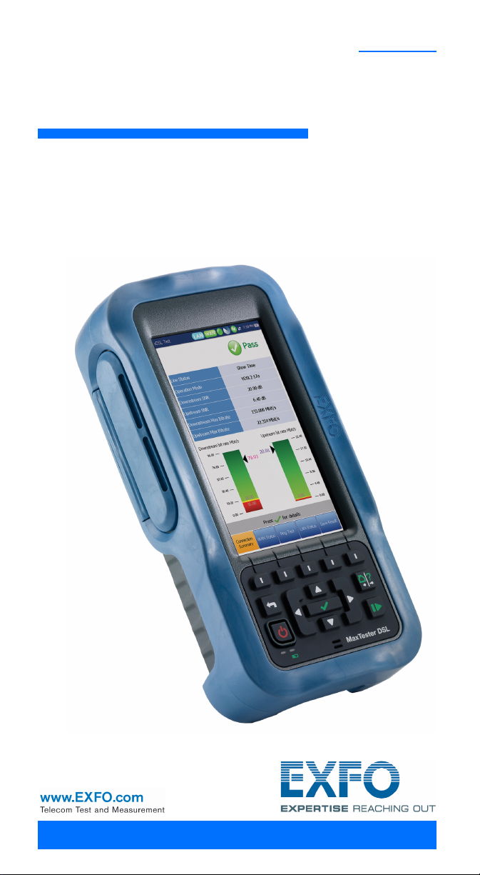
The MaxTester DSL is a handheld device designed for testing ADSL2+ and VDSL2
services between the service provider and the subscriber premises. In addition, the
dual Ethernet ports of the MaxTester DSL allow it to be used inside the home to test
all the way to the end point of the service.
Product Description
The MaxTester DSL Test Set case is an aluminum enclosure with rubber over mold,
which makes it ideal for field use. Its display is a back-lit LCD featuring 800 x 480
resolution. A membrane keypad mounted on the face of the unit features a
14-button keypad used to operate the test set. The following describes the features
of the MaxTester DSL.
Key Features and Benefits
³ Rugged and weatherproof handheld unit
³ Broadcom chipset
³ IP login
³ User-defined automatic testing
³ Dual Ethernet ports
³ Modem replacement
³ Battery powered
Typical Applications
³ ADSL2+ testing with optional VDSL2 for hybrid networks
³ Optional Web Browser, IPTV analysis, and data tests including Ping, FTP and
Traceroute testing
³ Ethernet testing for qualifying FTTx service at the customer premises
³ Configurable pass/fail results for automated testing
MaxTester DSL 1
Page 8
Introducing the MaxTester DSL Test Set 2
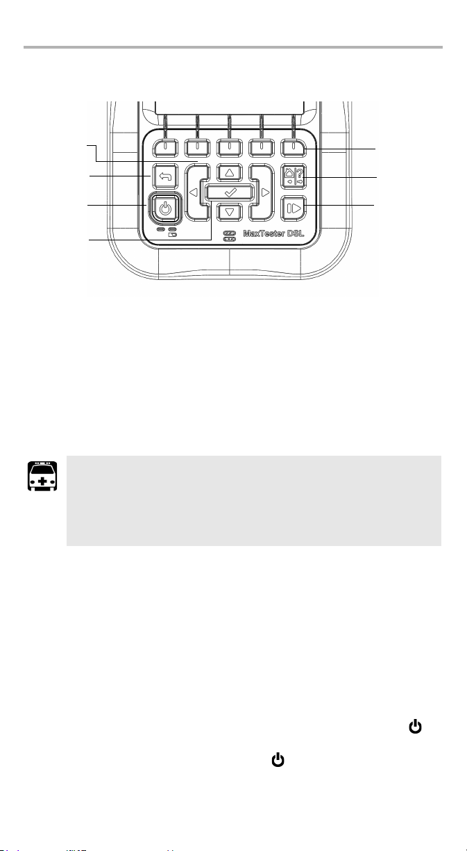
Function keys
Home/Help
Stop/Start test
Power
Back
Arrow keys
Enter
Keypad
³ Power: The button on the lower left side of the unit is used to power the unit on
and off.
³ Arrow Keys navigate the screen to access and modify parameters.
³ Function Keys activate the corresponding on-screen function button.
Battery
The MaxTester DSL is equipped with a Lithium-ion battery.
WARNING
³ Recharge the battery using only the MaxTester and with the
battery properly installed in the unit.
³ Never open the battery back panel of the MaxTester without
reading the Replacing the Battery section in this chapter.
When fully charged, the battery should provide between 3 and 10 hours of power
depending on different factors such as: type of tests performed, display backlight
level, and connected accessories.
To maximize battery power of the MaxTester DSL:
1. Lower the display backlight level using the application found in Display and
Language in the System settings, when the MaxTester DSL is used under low to
medium light conditions.
2. Disconnect any unused USB or SD accessories.
3. Quit any running tests when the MaxTester is not in use.
4. Whenever possible, put the MaxTester DSL in suspend mode by pressing for
less than 1 second,
5. When not in use, turn the unit off by pressing for at least 4 seconds.
Page 9

If the battery capacity remains low or outside the previously stated values, it should
be replaced. This could occur after 3 years depending on the usage.
Battery Calibration
In order to optimize the battery gas gauge accuracy, a battery calibration procedure
is accessible in the System menu under Power. See the Setting Up the MaxTester
DSL Test Set chapter. Going through this procedure may be necessary when first
using the MaxTester or after time depending on the number of charging cycles the
battery has undergone. It will optimize the gas gauge accuracy and not affect the
MaxTester's battery capacity.
Replacing the Battery
WARNING
Only use an EXFO battery. Batteries from other suppliers could result in
serious damage to the MaxTester or personal injuries. See the
Troubleshooting chapter for information on contacting EXFO.
Battery replacement should only be done by a qualified technician with the
appropriate tools on an electronic bench or similar environment.
To replace the battery:
1. Remove all 4 screws of the battery back panel using a 1.5 mm Allen key. Put
aside the screws and the panel keeping the inside foam seal clean. (See the
Back diagram under the Using the MaxTester DSL section in this chapter.)
2. Pull out the old battery using your fingers. Flipping the unit, battery-side down,
will ease removal. Do not use tools in order to prevent damage to the batter y
envelope. Pull out the electrical connector. Put aside the old battery.
3. Remove the new battery from its package. Keep the package for future use.
Plug in the electrical connector ensuring the pins are correctly aligned. Place
the new battery in the MaxTester.
4. Inspect the inside rib around the MaxTester battery compartment to make sure
it is free from any debris. Remove any debris using a dry cloth. Replace the
battery back panel. Replace the 4 screws with a moderate torque so the foam
seal is evenly compressed without damaging the screws.
Disposing of the Battery
Place the old battery in the replacement battery packaging. Properly dispose it
according to your local facilities for battery recycling.
MaxTester DSL 3
Page 10
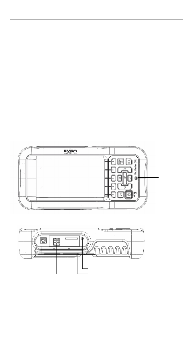
Introducing the MaxTester DSL Test Set 4
Speaker
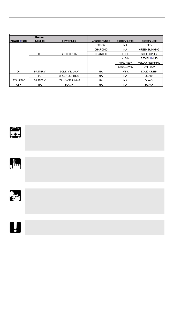
Battery LED
Power LED
USB Host Port
2 USB Client Ports
SD Card (not used)
Head Set Jack (2.5 mm) (not used)
Door
Caring for the MaxTester DSL
The MaxTester DSL has been designed to be a rugged and lightweight piece of test
equipment. However, the unit should be kept away from extremes of heat, cold,
moisture, and dust. Failure to do this may shorten the life of the instrument.
The MaxTester DSL LCD display should only be cleaned using a soft, lint-free cloth
and an anti-static cleaning solution. Ordinary detergents and other cleaning
solutions may cloud or scratch the surface and should be avoided.
Using the MaxTester DSL
The MaxTester DSL is rated IP54 which means that it is not affected by dust or water
splashing against the enclosure from any direction. This protection is only valid
when both side doors are properly closed. If the equipment is used in a manner not
specified by the manufacturer, the protection provided by the equipment may be
impaired.
The MaxTester DSL is equipped with a series of interfaces shown in the following
views:
³ Front
³ Left
Page 11
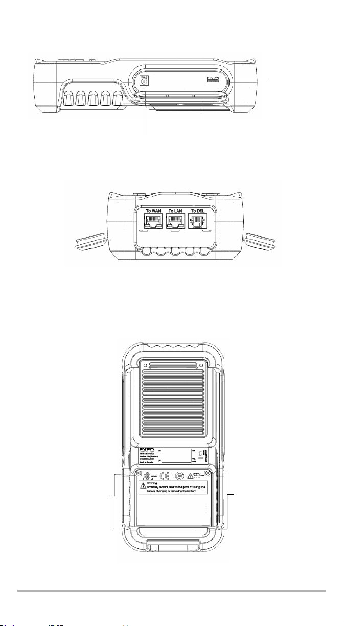
³ Right
DC Power Door
USB Client Port
Battery Door
Screws
Screws
³ Top
Note: When connecting a DSL cable to the WAN port, use the RJ-45 plug end of
the 26AWG cable provided with the unit. There is a 1500V maximum
transient voltage on telecom ports. Basic insulation is needed for
external telecom circuits.
³ Back
MaxTester DSL 5
Page 12
Introducing the MaxTester DSL Test Set 6
³ LED Legend
The MaxTester DSL enclosure may become warm during normal use.
Conventions
Before using the product described in this manual, you should understand the
following conventions:
WARNING
Indicates a potentially hazardous situation which, if not avoided,
could result in death or serious injury. Do not proceed unless you
understand and meet the required conditions.
CAUTION
Indicates a potentially hazardous situation which, if not avoided,
may result in minor or moderate injury. Do not proceed unless you
understand and meet the required conditions.
CAUTION
Indicates a potentially hazardous situation which, if not avoided,
may result in component damage. Do not proceed unless you
understand and meet the required conditions.
IMPORTANT
Refers to information about this product you should not overlook.
Page 13
2 Safety Information
IMPORTANT
When you see the following symbol on your unit , make
sure that you refer to the instructions provided in your user
documentation. Ensure that you understand and meet the required
conditions before using your product.
The AC adapter/charger provided with this unit (40 W/24 V) is specifically designed
to work with your MaxTester.
WARNING
³ Use the AC/DC adapter/charger indoors only.
³ Use only with a Class II AC/DC adapter, power limited output.
³ On the AC/DC adapter, replacing detachable mains supply cords
with inadequately rated cords, may result in overheating of the
cord and create a fire risk.
³ The adapter shall have the appropriate safety mark (e.g. UL,
CSA, TUV, CE, etc.) that is acceptable to the authorities in the
country where the equipment is to be used.
CAUTION
When using the MaxTester while connected to the AC/DC
adapter/charger, make sure you do not position the equipment so
that it is difficult to disconnect the adapter/charger from the
AC mains.
WARNING
Use only accessories that meet EXFO specifications.
MaxTester DSL 7
Page 14

Safety Information 8
Equipment Ratings
Te mp er at u re
³ Operation
³ Storage
Relative humidity (unit) 5 % to 95 % non-condensing
Maximum operation
altitude
Pollution degree 2(unit used inside; connected to AC mains or
Overvoltage category II
Power supply rating 100 V to 240 Vacc at 0.7A (50Hz/60Hz)
a. Use the external power supply indoors only.
b. Equipment should be normally protected against exposure to direct sunlight, precipitations and
full wind pressure.
c. Not exceeding ± 10 % of the nominal voltage.
0°C to 40°C (32°F to 104°F)
-20°C to 60°C (-4°F to 140°F)
3000 m (9843 ft)
powered by batteries)
a
3 (unit used outside; powered by batteries)
9-24 Vdc at 1.67 A
b
Page 15

3 Getting Started with the
MaxTester DSL Test Set
Turning the Unit On/Off
When you turn the unit on, you may use it immediately under normal conditions.
When the unit is turned off, it keeps the following parameters in its internal
memory:
³ Test parameters
³ User-defined thresholds
³ Regional, LCD, and energy-saving settings
³ Saved test results
There are two ways to turn off the MaxTester DSL Test Set
³ Suspend: the next time you turn your unit on, you will quickly return to your
work environment.
³ Shutdown: completely cuts power to the unit; the unit will perform a complete
restart routine the next time you use it. You should perform a shutdown if you do
not intend to use your unit for a week or more.
To t u rn t he u ni t on :
Press and hold for ½ to 1 second to start. The unit initializes for a few seconds
and displays the Home pane.
To enter suspend mode:
Hold down the key until the suspend notification sound plays, about 1 second.
The MaxTester will stay in suspend mode for 2 hours. After which it will
automatically shutdown. This prevents complete battery discharge and ensures
maximum battery performance.
To perform a shutdown:
Hold down the key for about 4 seconds. The shutdown process starts.
Note: In both previous cases, if the power adapter is plugged in, the unit will
MaxTester DSL 9
enter a charge mode instead of suspending or shutting down.
Page 16

Getting Started with the MaxTester DSL Test Set 10
Using Menus and Keypad
You can access various tools from the keypad or menu. Menu options may differ
depending on your unit configuration.
Home menu is where you can access either the various elements for your unit or
the system itself.
³ To navigate through the items, use the arrow keys.
³ To confirm a choice or enter a menu, press .
³ To cancel an action or return to the previous item or pane, press .
³ To return to the home pane, press .
Note: Pressing while a test is running will do nothing. The test can not be
running in order to return to the main menu screen.
Note: You can also select an option directly by pressing the function keys
corresponding to the on-screen buttons at the bottom of the screen.
Using Online Help
Online help is available at any time. Most test operations pause while you view help,
but will resume automatically when you exit help.
To access help about the current function at any time:
Press and hold the ? key.
Page 17
4 Setting Up the MaxTester
DSL Test Set
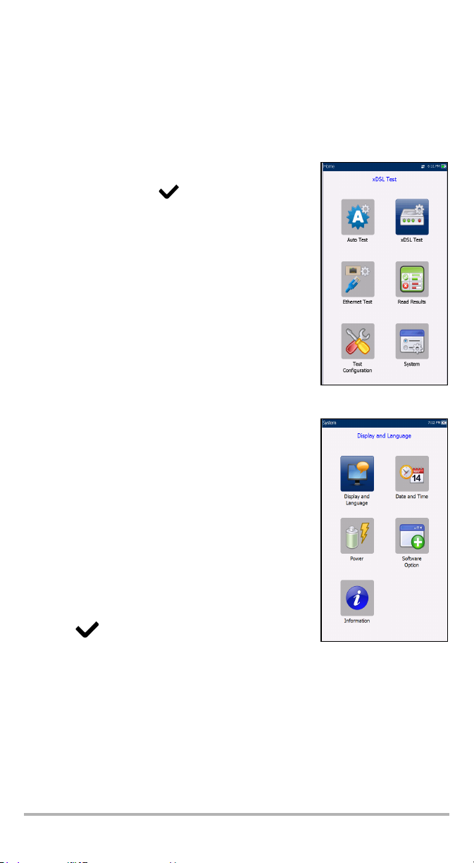
Main Menu Page - Home
Home presents the main menu page which allows you to
navigate to each icon using the up/down left/right arrow
keys on the keypad. Press to bring up the sub-menu
of the selected icon:
³ For Auto, xDSL, or Ethernet Test, the test will start
and the screen control will navigate to the Result
Summary page.
³ Read Results opens the Read Results page of the
previously saved tests.
³ Test Configuration provides the utilities to setup test
parameters.
³ System allows you to set the parameters of the unit.
System Settings
System presents a menu of items to setup the unit.
³ Display & Language provides the setup for backlight,
information on the title bar, and language choice.
³ Date & Time sets the date and time and format.
³ Power displays the battery status and power scheme.
³ Software Options allows you to enable/disable
purchased feature options.
³ Information shows unit details pertaining to
hardware/software/product info.
To navigate between the system settings:
1. Press the up/down left/right arrow keys on the keypad
to select an icon.
2. Press to confirm your selection.
MaxTester DSL 11
Page 18
Setting Up the MaxTester DSL Test Set 12
Display and Language
To fit your work environment, you may adjust the LCD
brightness, and display the time, Active Sync and power
status.
Note: The LCD backlight consumes battery power;
more brightness, more power consumption.
This is also where you can change the display language.
The values are kept in memory when you turn the unit off.
To adjust the display settings:
1. Press , select System, and then Display &
Language.
2. Use the up/down arrow keys to select the setting to
change.
3. Press to select it.
³ You can switch between preset brightness levels in the Backlight item.
Press to con fir m .
³ Enable or disable the time, Active Sync, and modem power status, then
confirm the choice with the key.
³ Use the up/down arrow keys to navigate between the available languages,
then press
to select it. You will be prompted to restart your unit.
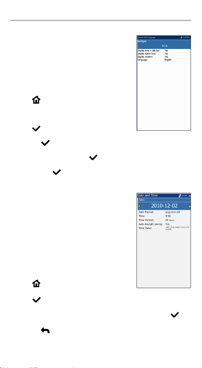
Date and Time
When saving results, the unit also saves the
corresponding date and time.
You can enter the date according to the following formats:
³ yyyy-mm-dd
³ dd-mm-yyyy
³ mm-dd-yyyy
The time can be set according to the 12- or 24-hour
formats.
You can also modify the time zone and enable an option
so that your unit automatically adjusts the time for the
daylight saving period.
To set the date and time:
1. Press , select System, and then Date & Time.
2. Use the arrows to select any of the date or time settings.
3. Press to enable the modification controls.
³ For the date and time, an edit screen is displayed with descriptive function
keys. Use the arrow keys to modify the number values, then press to
confirm the change and go back to the previous screen.
Press to go back to the previous screen without saving the new value.
Page 19
³ For the time format, auto daylight saving and time zone values, use the
arrow keys to select the desired value, then press to confirm the
change.
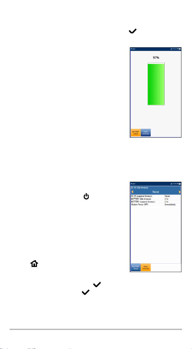
Power - Battery Status
The BATTERY Status pane indicates the current power
level for the battery.
Note: The battery level might not display after a
system upgrade but will become available
again after the next full charge.
Power Schemes
You can set your unit to automatically switch to suspend mode independently for
the battery or AC power modes. This is useful for example if you want to save
battery power but do not want to be hindered by unwanted switches between
modes when using AC power.
³ Power off completely shuts down the unit’s power.
³ Power suspend puts the unit in sleep mode; you can
wake up the system by pressing power on/off
button.
³ Modem power off:
³ Immediately for when an xDSL test is completed
or stopped. In this mode, the modem is powered
on when xDSL test starts.
³ Timeout value powers off the modem within a
defined period after an xDSL test is completed or
stopped.
To change the power management settings:
1. Press , select System, and then Power.
2. Select the Power Schemes tab.
3. Under DC In or Battery, use the arrow keys to select power off on system idle or
suspend timeout modes, then press to view the list of available choices.
4. Select a new value, then press to confirm the choice. Repeat for the other
modes as needed.
MaxTester DSL 13
Page 20
Setting Up the MaxTester DSL Test Set 14
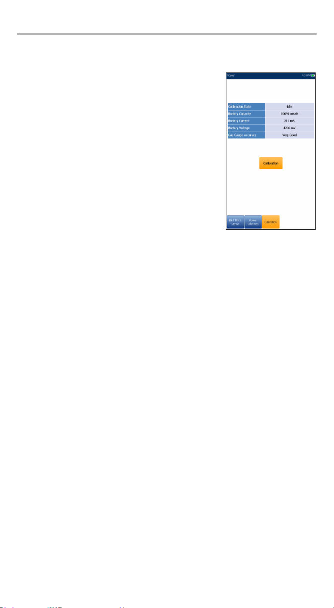
Power - Calibration
The Calibration tab allows you to optimize the battery gas gauge accuracy.
³ Calibration State:
³ Completed displays after the calibration
procedure has been started and the DC plug was
not removed before the end was reached.
³ In Progress displays when the calibration
procedure has been started but has not yet
reached the end.
³ Aborted displays when the calibration procedure
has been started but the DC plug was removed
before the end.
³ Idle displays after the next MaxTester cold boot.
³ Gas Gauge Accuracy indicates the estimated battery
gas gauge accuracy.
³ Below 10 % accuracy error is Very Good.
³ Between 10 % and 20 % accuracy error is Good.
³ Over 20 % accuracy error is Poor and a gas gauge calibration is needed in
order to get optimal accuracy.
The following on-screen messages may appear:
³ Calibration Completed is displayed after the procedure has been started and
successfully completed.
³ Calibration In Progress is displayed when the procedure has been started and
not yet completed.
³ Calibration Aborted is displayed when the procedure has been started but the
DC plug was removed or a power failure occurred before the end, or if you
terminate the calibration.
To start the gas gauge calibration:
1. Select the Calibration button. Completion time is up to 20 hours depending on
the MaxTester's initial battery level and current power consumption.
2. Make sure the DC plug always stays connected and the unit is not turned off
until completion. Failing to do so will abort the procedure and previous
calibration parameters will be kept.
Note: No other activity can be performed on the unit during calibration.
Note: Going through this calibration does not affect the MaxTester's battery
capacity.
Page 21
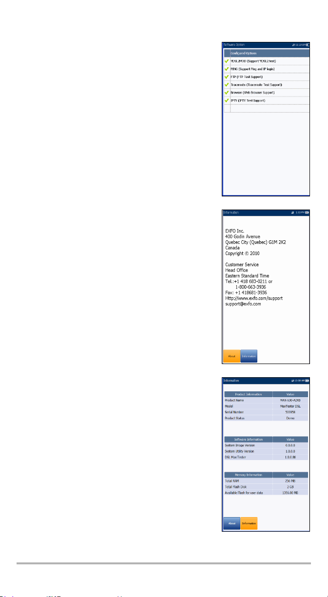
Software Option
This screen lists all the Configured Options which are
present on the unit.
Information - About EXFO
The About tab contains contact information should you
require technical assistance.
MaxTester DSL Information
The Information tab displays information about the
product, software, and memory installed on the device.
MaxTester DSL 15
Page 22
Configuring the MaxTester DSL Test Set 16
5 Configuring the
MaxTester DSL Test Set
Test Configuration
The MaxTester DSL supports 3 types of test applications: Auto Test, xDSL Test, and
Ethernet Test. Configuration parameters for all 3 test applications are saved into a
test configuration profile. A default profile is provided with a predefined set of
parameters for all test applications.
³ Select Profile lists saved available profiles. The
current active profile is shown in the upper
information header. At power up, settings are read
from the last loaded profile.
³ Profile Details lists the 3 types of tests for
configuration:
³ Auto Test Setup
³ xDSL Test Setup
³ Ethernet Test Setup
³ Factory Default resets system profiles to factory
default settings. Currently selected profiles, other than
system profiles, are not affected.
³ Clone Profile allows you to create a new profile by
copying all parameters from the currently loaded
profile.
³ Import Profile allows you to copy all profiles from external USB key to the unit.
³ Export to USB allows you to copy all profiles to USB key.
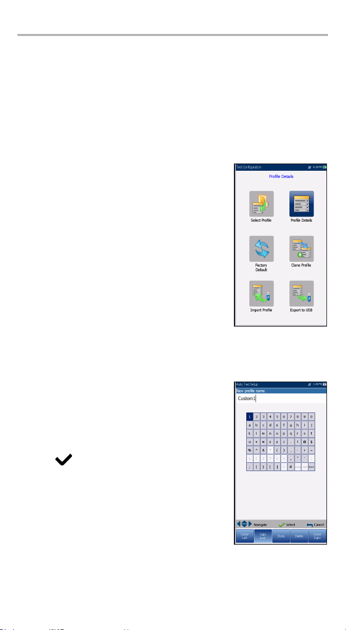
Setup Profile Name
This alphanumeric editor screen allows you to change
parameter values and save changes to a new profile.
To use the editor screen:
1. Press the up/down left/right arrows to navigate the
on-screen keyboard.
2. Press to confirm the selection.
Page 23
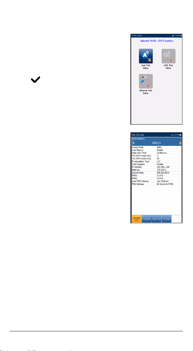
Profile Details Menu
You can view any of your saved profiles on the MaxTester
DSL from the Profile Details menu by selecting the desired
test setup icon. This sub-menu displays an icon for each
test: Auto Test, xDSL, and Ethernet.
To select a test:
1. Press the up/down left/right navigation keys to select
the desired icon.
2. Press to display the test profile details.
Connection Setup
The Connection Setup tab allows you to configure the
following option setup fields:
³ Test I n t e rfac e is either
³ ADSL2+ - configured as multi mode
(G.992.1/2/3/5 T1.413, ANSI,) or
³ VDSL2 - only available if the VDSL2 Software
Option is activated. VDSL2 configuration allows
fallback to ADSL.
³ Ethernet
³ Access Mode options are dependent on the Test
Interface selection:
³ If ADSL2+ - then Sync only, Bridged (not in Auto
Test), DHCP, Static, PPPoE, PPPoA, IPoA
³ If VDSL2 - then Sync only, Bridged (not in Auto
Test), DHCP, Static, PPPoE
For x DS L , d e f a u l t i s Bridged.
³ For Ethernet - DHCP, Static, PPPoE, Bridged.
³ Auto Resync allows you to Enable the SyncLossCounter as the Pass/Fail criteria.
When SyncLossCounter+1 is reached, the test will have fail status.
If Auto Resync is disabled, any time the test loses sync, the result status will be
fail and the test will stop automatically.
³ Keep Sync Time is either
³ Continuous - the test runs until you manually stop it, or
³ set to a time period. Default is 5 minutes.
³ VLAN Support enables the unit to analyze and pass WAN tagged ethernet
frames through the virtual local area network (VLAN).
MaxTester DSL 17
Page 24

Configuring the MaxTester DSL Test Set 18
³ VLAN ID is a virtual local area network (VLAN) tag ranging from 0 through 4094.
The entry is available only when VLAN Support is Enable.
³ Vendor ID is the name of the unit. This entry is available only when Access
Mode is DHCP.
³ VPI (ATM mode only) is the virtual path identifier (VPI) ranging from 0 through
255 for the downstream channel.
³ VCI (ATM mode only) is the virtual circuit identifier (VCI) ranging from 32
through 65535 for the downstream channel.
³ Encapsulation Type depends on the network configuration and sets the ATM to
either LLC also known as LLC-SNAP (logical link control-sub network address
protocol) or VC_MUX (virtual channel multiplex).
³ Local Mac Address is the internal MAC address of the unit: either MaxTester or
User Defined.
³ Mac Address is a specific MAC address, in a hexadecimal format, if
User Defined was selected for the previous parameter. This entry is available
only when Access Mode is DHCP, Static for ADSL2+.
³ Static IP is the address of the current location assigned by the service provider.
This entry is available only if Obtain IP is set to Static.
The following parameters are available only when Access Mode is PPPoE or PPPoA.
³ Login Name is your user ID.
³ Passw ord is your password.
³ Obtain IP is either Dynamic where the access concentrator or broadband
remote access server assigns a temporary IP address to the unit, or Static
where you enter the IP address of the unit.
³ WAN Login Tim eou t is a numeric setup field.
The following parameters are available only when Access Mode is IPoA or Static.
³ IP Address is the address for the unit that is actively connected to your
network or the internet at the time of login.
³ Gateway is the IP address of the default gateway.
³ Subnet Mask is the network address used to identify if the IP address is
within the same wide area network.
³ DNS1 is the address of the primary domain name server to be used by the
unit. If DNS is unavailable, enter 0.0.0.0.
³ DNS2 is the address of the secondary domain name server to be used by
the unit. If DNS is unavailable, enter 0.0.0.0.
The following parameters are available only when Tes t I n te rfac e is Ethernet.
³ WAN/LAN Link Speed is a choice between AUTO (negotiated during the
link establishment), 100 or 10 Mbit/s.
³ WAN/LAN Connect Mode is Full or Half Duplex, when Link Speed is set to
either 100 or 10 Mbit/s.
Page 25
To configure options in the setup fields:
1. Press the up/down arrows to select the desired parameter.
2. Press the left/right arrow keys to view and select the options.
3. If you make any changes to the parameter values, press the on-screen function
keys to save or cancel your input.
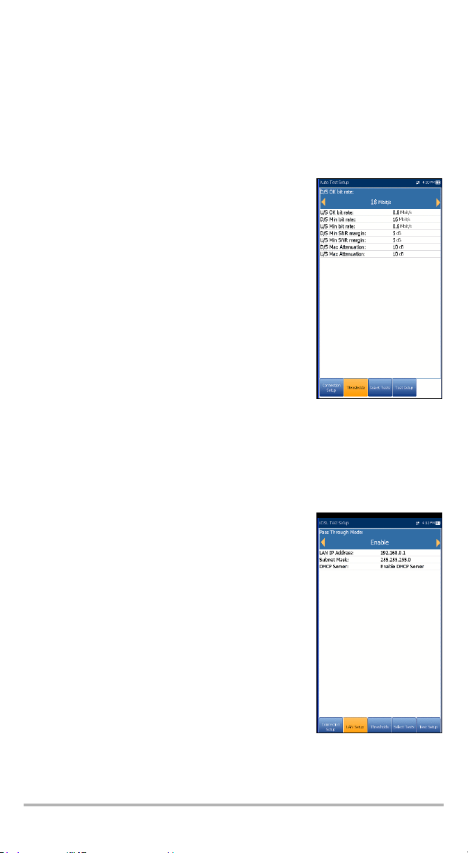
Thresholds
The Thresholds tab defines DSL parameter criteria. For
D/S (downstream) and U/S (upstream) data rates, there
are OK and Min (minimum) bit rates defined to indicate
unacceptable, marginal, and acceptable rates.
³ D/S and U/S OK bit rate (Kbit/s):
³ for ADSL - value limited to D/S 30 Mbit/s,
U/S 2 Mbit/s.
³ for VDSL - D/S to 100 Mbit/s, U/S to 50 MBit/s.
³ D/S and U/S Min SNR margin (dB) - values range from
0 to 63.5. Default is 5.
³ D/S and U/S Max Attenuation (dB) - values range
from 0 to 128. Default is 10.
To s e t t h re s ho l d v a l ue s :
1. Press the up/down arrows to select the desired
parameter.
2. Press the left/right arrow keys to view and select the options.
3. If you make any changes to the parameter values, press the on-screen function
keys to save or cancel your input.
LAN Setup
The LAN Setup tab is available only in xDSL test setup and
when the Access Mode set in Connection Setup is not
Sync Only. LAN Setup allows you to configure the
parameters required when working in Pass Through
Mode, and the LAN (local area network) is connected to
the external device which supports 10/100 Ethernet.
This tab is not available in Auto Test Setup.
³ Pass Through Mode - Enable or Disable.
³ LAN IP Address is the local network IP address of the
unit.
³ Subnet Mask is the network address mask used to
identify if the IP address is within the same local area
network.
MaxTester DSL 19
Page 26

Configuring the MaxTester DSL Test Set 20
³ DHCP Server enables the dynamic host configuration protocol (DHCP) mode
for the LAN side of the connection.
³ Platform Ip Address displays the IP address of the unit’s platform when the
DHCP Server is disabled.
To configure LAN setup values:
1. Press the up/down arrows to select the desired parameter.
2. Press the left/right arrow keys to view and select the options.
3. If you make any changes to the parameter values, press the on-screen function
keys to save or cancel your input.
Select Tests
The Select Tests page allows you to Enable/Disable the
following optional sub-tests, within the 3 types of test
applications.
³ IPTV Test - when enabled, all other sub-tests are
automatically disabled.
³ Ping is also known as ICMP echo request and
determines network connectivity and accessibility.
³ FTP test verifies the file transfer speed of the file
download and upload.
³ Tracer out e is a complement tool of the Ping test to
determine why a destination cannot be reached, or
where the internet is broken.
³ Web Brow ser Test can only be started when a WAN
connection (either through xDSL or Ethernet) has
been established.
When enabled, the sub-tests’ test pages are available in the results pages.
When highlighted, the sub-tests’ setup contents are shown on the Test Setup tab.
Note: Select Tests and Te s t S et u p tabs are not
available in Sync Only and
Bridged Access Modes.
To select sub-tests:
1. Press the up/down arrows to highlight the desired test.
2. Press the left/right arrow keys to toggle between Enable/Disable.
OR
3. Press on any value to open the list box to toggle between Enable/Disable.
Page 27

Test Setu p
The Test Setup tab allows you to configure values for the optional sub-tests within
the 3 types of test applications. You must highlight the sub-test on the Select Tests
page in order to display the sub-test’s parameters on the Test Setup page.
IPTV Test Setup
IPTV test supports STB (set-top box) emulation mode over
xDSL and Ethernet interfaces enabling the MaxTester to
join and leave multicast IPTV streams. The following
parameters can be configured from the Test Setup tab:
³ Display Mode is either the Channel Name or # used
for displaying channel information in the result pages.
³ IGMP Version is a value of either 2 or 3 used to send
IGMP join/leave messages.
Note: If you change the IGMP Version from the
default of 2 to 3, you must reboot your unit.
³ Max TS Packet Loss Ratio is an editable percentage,
ranging from 1 to 50, used to qualify if the IPTV stream
is stable.
³ Max ZAP Time is an editable value ranging from 0 to 10,000 that measures the
channel switch time in ms.
³ Channel List Setup button accesses the page to configure parameters for
channel analysis.
³ Auto IPTV Test Setup button accesses the setup page to automatically run an
IPTV test. This function is only available in Auto Test Setup application.
To configure test setup values:
1. Press the up/down arrow keys to select the desired parameter.
2. Press the left/right arrow keys to view and select the options.
OR
3. Press on a value to open a list box of options or the alphanumeric editor
screen and use the navigation keys to scroll through.
4. Press to confirm the value.
5. If you make any changes to the parameter values, press the on-screen function
keys to save or cancel your input.
MaxTester DSL 21
Page 28

Configuring the MaxTester DSL Test Set 22
Channel List Setup
The Channel List Setup page in the IPTV test setup
provides a tool for you to create an alias table. It allows
you to join/leave an IPTV stream using a symbolic name
or TV channel number instead of the IP address.
Maximum entries in the table are 100, divided into pages.
³ The channel list displays 3 editable parameters:
³ Channel # is a numeric value from 1 to 9999.
³ Channel Name is a 24-character alphanumeric
field.
³ IP address is a numeric value.
³ Previous/Next Entry buttons highlight the
previous/next entry in the table (up/down direction).
When the highlight reaches the first/last entry of the
alias table page, the button(s) is disabled.
³ On-screen function buttons:
³ Add/Insert adds currently edited channel info into the alias table below the
highlighted entry and moves the highlight to the newly added entry. If the
page is full, the bottom entry moves to the next page. Selecting the highlight
placement allows you add and group entries with similar parameters.
³ Delete removes the highlighted entry in the alias table. If the deleted entry
was also present in the IPTV Channel Analysis list or Join/leave Test list in
Auto IPTV Test Setup page, it will also be removed from those lists.
³ Accept replaces the edited value for the current highlighted entry. Use this
function for modification purposes.
³ Page U p/Down display the previous/next page(s) of the alias table. If current
page is the first/last page, the button(s) are disabled.
To setup the channel list:
1. Press the up/down, right/left keys to select the desired channel parameter.
2. Use the on-screen function buttons to create or edit the channel list.
OR
3. Use the navigation keys to select the Previous/Next Entry button(s) and press
to select the entry to be highlighted and edited.
Page 29

Auto IPTV Test Setup
The Auto IPTV Test Setup page in the IPTV test setup
allows you to define 2 types of IPTV tests to run
automatically:
³ IPTV Channel Analysis - Enable to add channels for
analysis. If disabled, channel analysis in auto test is
not performed.
³ Stream Time defines the length of time, from 1 to
60 s, to keep the channel stream(s) for analysis.
³ Channel 1-5 allows you to define up to 5 IPTV
channels for concurrent analysis.
³ Join/leave Test - Enable to define a list of channels to
sequentially join and leave. If disabled, no test is
performed.
³ Channel 1-10 allows you to define a list of up to
10 channels.
³ On-screen function buttons:
³ Add/Insert is available only when a blank entry is highlighted. When the
button is pressed, the first available channel from the alias Channel List is
automatically added to this list of channels. Upon highlighting another blank
entry, the next channel from the alias table is added, and so on.
³ Delete removes the selected channel from the list.
You can Enable either one or both, but you cannot Disable both of them at same
time. If both tests are enabled, Join/leave Test runs first.
To configure test setup values:
1. Press the up/down arrow keys to select the desired parameter.
2. Press the left/right arrow keys to view and select the options.
OR
3. Press on a value to open a list box of options or the alphanumeric editor
screen and use the navigation keys to scroll through.
4. Press to confirm the value.
MaxTester DSL 23
Page 30

Configuring the MaxTester DSL Test Set 24
Ping Test Setup
The Test Setup tab is available only if Access Mode is not
Sync only.
³ Address Format is URL, IP Address or Gateway.
³ URL/IP Address lists either the URL or IP Address
where the unit pings.
³ Packe t Size is a value from 32 through 1200 of the
number of bytes sent in one packet. The default value
is 32.
³ Tota l P i ng s is the total number of Ping packets to
send out from1 through 99. The default value is 3.
³ Timeout is the time in seconds from 1 through 10, that
the unit will wait for a response back from the
destination device.
To configure test setup values:
1. Press the up/down arrow keys to select the desired parameter.
2. Press the left/right arrow keys to view and select the options.
OR
3. Press on a value to open a list box of options or the alphanumeric editor
screen and use the navigation keys to scroll through.
4. Press to confirm the value.
5. If you make any changes to the parameter values, press the on-screen function
keys to save or cancel your input.
FTP Test Setup
The FTP test verifies the file transfer speed of the file
download and upload. The FTP Test Setup tab allows you
to configure the following parameters:
³ Address Format is URL or IP Address.
³ FTP Server Address lists either the URL or IP
Address.
³ Login Name/Password is your user ID and password.
³ Download File Name is the filename requested for
downloading, maximum 128 characters.
³ Upload File Name is the filename used for uploading,
maximum 128 characters.
³ Upload File Size (kB) is the number of bytes or size
of the file to be uploaded to the server.
³ File Upload/Download - Enable/Disable options
available only in Auto Test Setup. Enable to perform the upload/download
operation automatically.
Page 31

To configure test setup values:
1. Press the up/down arrow keys to select the desired parameter.
2. Press the left/right arrow keys to view and select the options.
OR
3. Press on a value to open a list box of options or the alphanumeric editor
screen and use the navigation keys to scroll through.
4. Press to confirm the value.
5. If you make any changes to the parameter values, press the on-screen function
keys to save or cancel your input.
Traceroute Test Setup
The Traceroute Test Setup tab allows you the configure
the following parameters:
³ Address Format is URL or IP Address.
³ Destination Address is the destination IP or URL
address.
³ Max Hops specifies the maximum number of hops
(1 to 32) used in attempting to reach the destination
address.
³ Timeout is the time in seconds from 1 to 10, that the
unit will wait for a response back from the destination
device.
To configure test setup values:
1. Press the up/down arrow keys to select the desired
parameter.
2. Press the left/right arrow keys to view and select the options.
OR
3. Press on a value to open a list box of options or the alphanumeric editor
screen and use the navigation keys to scroll through.
4. Press to confirm the value.
5. If you make any changes to the parameter values, press the on-screen function
keys to save or cancel your input.
MaxTester DSL 25
Page 32
Configuring the MaxTester DSL Test Set 26
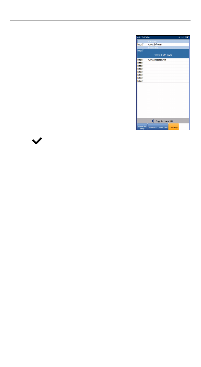
Web Browser Test Setup
The Test Setup page for the Web browser content is
displayed when the Web Browser Test is highlighted on
the previous Select Tests tab. Here you can edit the
Bookmarks and Home URL.
³ Bookmarks lists 9 entries. The default is http://.
The Bookmarks list is shared by all 3 tests (Auto Test, xDSL
and Ethernet tests). If the list is changed in one test, the
changes are reflected in the other two.
³ Home URL acts as the Home URL for the Web
browser test page when launched. It is independent
among the 3 types of test applications.
³ Copy to Home URL allows you to set a highlighted
URL as the Home URL.
To configure the Web browser setup:
1. Press the up/down arrows to highlight the desired entry in the list.
2. Press to access the edit screen.
3. If you make any changes to the test values, press the on-screen function keys to
save or cancel your input.
Page 33
6 MaxTester DSL Test
Results
The MaxTester DSL is designed to make xDSL turn-up easy. The unit will emulate an
ATU-R to the point that it can handshake and connect with an ATU-C and report the
upstream and downstream parameters. Simply connect to the line, turn on the
MaxTester DSL, and select a test to run. Results obtained include upstream and
downstream throughput and noise margin.
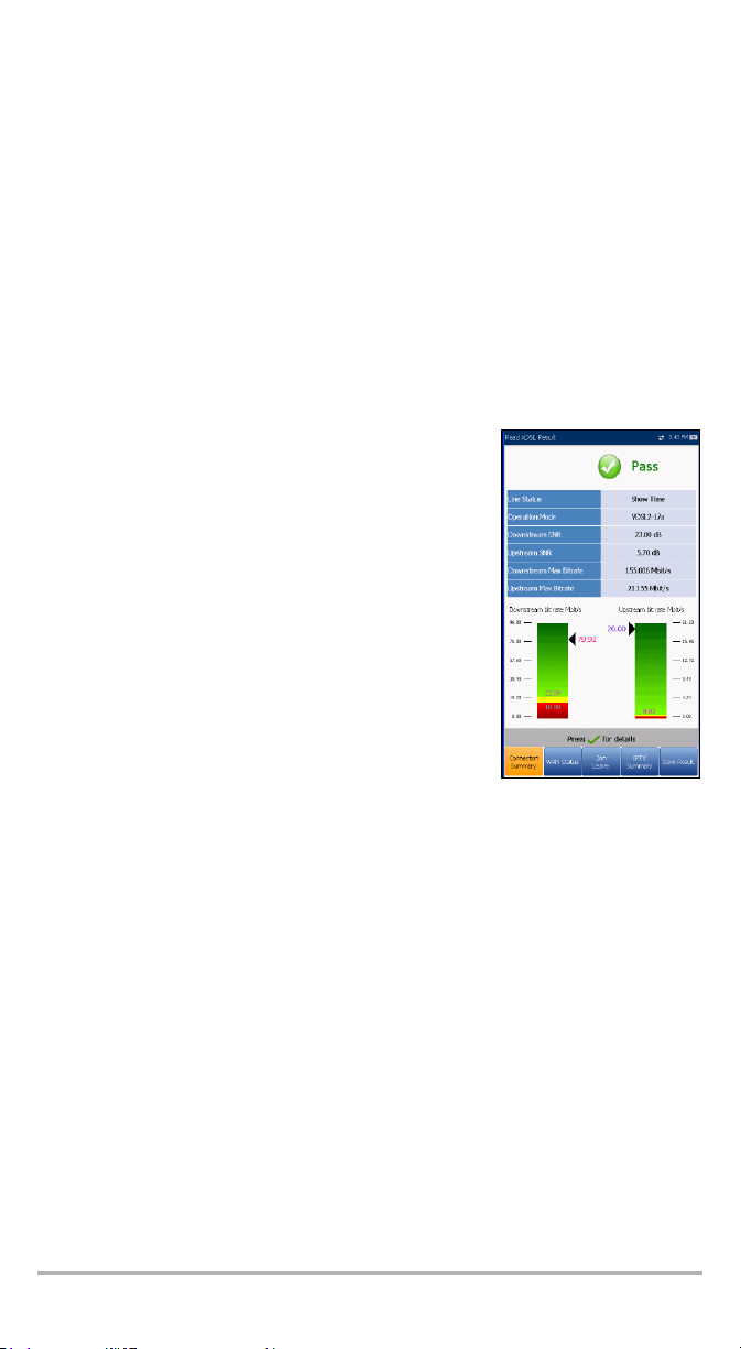
xDSL Connection Summary
The Connection Summary tab allows you to view the pass/fail status and details of
the test results.
³ Line Status displays the status of the line under test
during negotiation with the DSLAM. The value
changes from Idle /Activate /Handshake /Training
/Showtime for ADSL2+ or VDSL2 mode.
³ Operation Mode is the xDSL mode of operation as
negotiated between the unit and the DSLAM.
³ Downstream/Upstream SNR is a value ranging from 0
through 63.5 for the minimum SNR (signal-to-noise
ratio) margin.
³ Downstream/Upstream Max Bitrate displays the D/S
(downstream) and U/S (upstream) maximum
attainable bit rates that the circuit can handle as
determined by the remote terminal and CO during the
training phase. Values can be greater than the actual
bit rate.
³ Downstream/Upstream actual bit rates are displayed by graphic bars and the
current actual values appear as numbers.
³ Downstream bit rate value is shown in yellow region if it is greater than Min
threshold and less than OK threshold.
³ Upstream bit rate value is shown in yellow region if it is greater than Min
threshold and less than OK threshold.
³ Downstream bit rate value is shown in red region if it is less than
Min threshold.
³ Upstream bit rate value is shown in red region if it is less than Min threshold.
MaxTester DSL 27
Page 34
MaxTester DSL Test Results 28
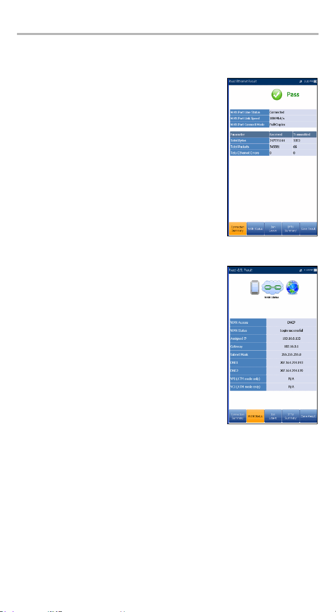
Ethernet Connection Summary
When set up over Ethernet, the available test results are the following:
³ WAN/LAN Port Line Status displays either Connected
or Disconnected for the particular line connection
under test.
³ WAN/LAN Port LinkSpeed is a choice between AUTO
(negotiated during the link establishment), 100 or
10 Mbps.
³ WAN/LAN Port ConnectMode is Full-Duplex or
Half-Duplex, when Link Speed is set to either 100 or
10 Mbps.
³ The total number of Received and Transmitted
Bytes, Packets, and Ethernet Errors are also
displayed during the test.
WAN Status
The WAN Status tab allows you to view the status of the connection between the
WAN port of the unit and the ISP.
³ WAN Access specifies the encapsulation method used
by the network and consists of the following types:
³ PPPoE is point-to-point protocol over Ethernet.
³ PPPoA is point-to-point protocol over ATM.
³ DHCP is Dynamic Host Control Protocol which is
used to dynamically assign an IP address for the
client node on the network.
³ Static IP is the current location assigned by the
service provider or user.
³ IPoA stands for classical Internet Protocol over
ATM .
³ WAN Status value changes as per current WAN Status.
³ Assigned IP displays IP address information assigned
to the unit that is connected to the network.
³ Gateway is the IP address of the default gateway.
³ Subnet Mask is the network address used to identify if the IP address is within
the same WAN.
³ DNS1 is the address of the primary domain name server to be used by the unit.
³ DNS2 is the address of the secondary domain name server to be used by
the unit.
³ VPI is the virtual path identifier value. Not available in PTM mode.
³ VCI is the virtual circuit identifier value. Not available in PTM mode.
Page 35
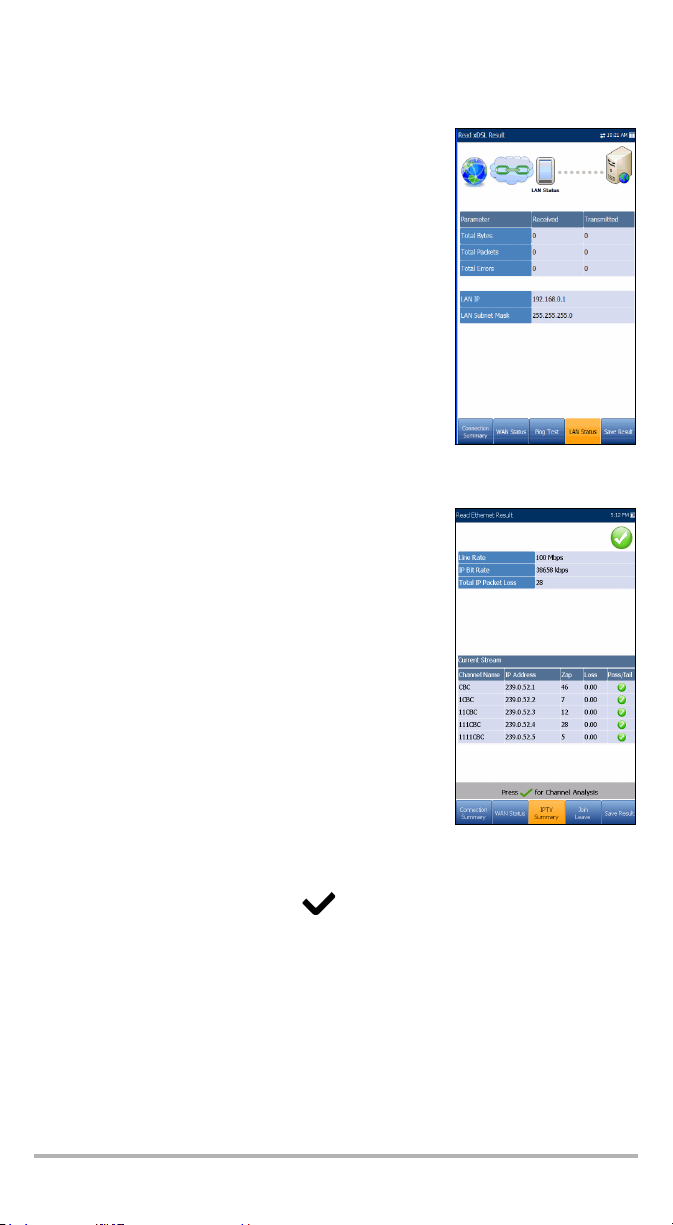
LAN Status
The LAN Status tab allows you to view the customer
information configured for the LAN (local area network).
³ LAN IP is the local network IP address of the unit.
³ LAN Subnet Mask is the network address mask used
to identify if the IP address is within the same local
area network.
³ The total number of Received and Transmitted
Bytes, Packets, and Errors are also displayed during
the test.
IPTV Summary
The IPTV Summary tab allows you to view the pass/fail
status and test results of the IPTV streams and actions
(Join/Leave).
³ Line Rate is the actual rate achieved by the circuit,
in Mbps.
³ IP Bit Rate is the IP data rate for the IPTV service,
including all channels detected.
³ Total IP Packet Loss is the total number of packets
lost, with errors, or out of sequence, during the
test period.
³ Current Stream lists a maximum of 5 live channel
streams by name and IP Address.
³ Zap is the time in ms, required for a channel
change or join, and is one of the key factors to be
considered when evaluating the IPTV quality of
service (QoS).
³ Loss is the percentage of IP packet loss during the last one-second period.
To view the Channel Analysis, press from the IPTV Summary tab.
MaxTester DSL 29
Page 36
MaxTester DSL Test Results 30
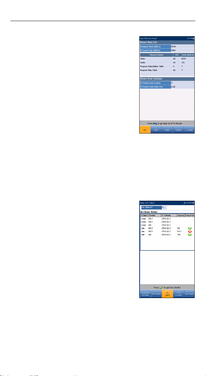
Channel Analysis
The Channel Analysis function provides a separate tab for
every live stream channel. Each channel displays the
following information:
³ Stream Rate Info
³ Transport Rate (kbit/s)
³ IP Packet Rate (kbit/s)
³ Stream Content lists the statistical information about
the Video, Audio and Program Association/Map
Tab le (s) content for each MPEG video
analyzed stream.
³ PID is a unique integer value or packet identifier
(PID) that indicates the type of data that is stored
in the packet payload of the video stream.
³ Rate (kbit/s) is the rate calculated of a given
stream content.
³ Stream Error Indicator
³ TS Packet Loss Counter is the number of packets lost, with errors, or out of
sequence, during the test period in the transport stream.
³ TS Packet Loss Ratio (%) is the percentage of IP packet loss during a one
second period in the transport stream.
Join Leave
The Join Leave tab displays a list of IPTV channels from
the alias table, their activity (measured Zap time), and
pass/fail status. Upon successful WAN connection, the
Join/Leave Channel lists and Join and Leave buttons
are shown.
Note: Join and Leave buttons are not shown in
Auto Test since join and leave are
automatically executed.
To join/leave channels:
1. Pres s Join to have the STB send an IGMP report with
the multicast IP address.
2. Pres s Leave to inform the network to stop sending the
current stream.
Page 37

DSL Parameter Details
The DSL Param Details tab displays the Downstream and Upstream parameter
results configured in the xDSL tests.
³ Line Status displays the status of the line under test
during negotiation with the DSLAM. The value
changes from Idle /Activate /Handshake /Training
/Show Time for ADSL2+ or VDSL2 mode.
³ Operation Mode is the DSL mode of operation as
negotiated between the unit and the DSLAM.
³ CO Vendor ID is a unique 4-digit alphanumeric
identifier of the DSL chipset manufacturer used on the
CO (central office) side.
³ CO Version is the version number of the unique
alphanumeric identifier of the DSL chipset used on
the CO side.
³ Sync loss count is the number of times the unit lost
synchronization.
³ Parameters - Downstream/Upstream
³ Actual Data Rate displays the values at which the unit and CO are
connected, as negotiated during the training phase. The values should
represent what the CO was set to, unless the DSL link is being subjected to
high levels of noise/crosstalk, and are typically what the DSLAM has been
set to, whether interleaved or fast.
³ SNR is the signal-to-noise ratio margin measured on the line.
³ Attenuation is line attenuation measured during the training phase.
³ Capacity is the capacity of the line as a ratio of achieved bit rate over the
maximum attainable bit rate presented as a percentage (%). A high value
could mean that the link is nearing its maximum capabilities while a low
value could mean the link is being under utilized (sometimes intentionally –
verify your local DSLAM setup).
³ Maximum Data Rate displays the maximum attainable bit rates that the
circuit can handle as determined by the remote terminal and CO during the
training phase. Values can be greater than the actual bit rate.
³ Output Power is the current transmit power level that is a measure of the
aggregated transmit power.
³ Latency is the path type, Fast or Interleave, set by the service provider at
the CO. The use of the interleaved path means greater delay in the deliver y
of data but it is less susceptible to noise or crosstalk due to increased
Reed-Solomon coding and FEC (forward error checking). The use of the
fast path means little or no delay in the delivery of data but it is more
susceptible to noise and crosstalk.
³ Interleave Delay defines the mapping (relative spacing) between
subsequent input bytes at the interleave input and their placement in the bit
stream at the interleave output.
³ INP is the level of impulse noise protection.
MaxTester DSL 31
Page 38
MaxTester DSL Test Results 32
³ Interleave Depth defines the number of bits (or bytes) in each block of
data.
³ Bitswap specifies the status of the bit swapping mechanism - Active, Not
Active or Unknown - swapping bits from tone m to tone n to prevent
modem retraining.
³ Trelli s or Trellis Coded Modulation (TCM) is a type of convolutional code
which utilizes parity bits on each symbol within a continuous data stream.
When the line is connected, Trellis displays either On or Off.
³ Phy-R is Broadcom proprietary Physical Layer Retransmit technology which
is used to overcome impulse noise.
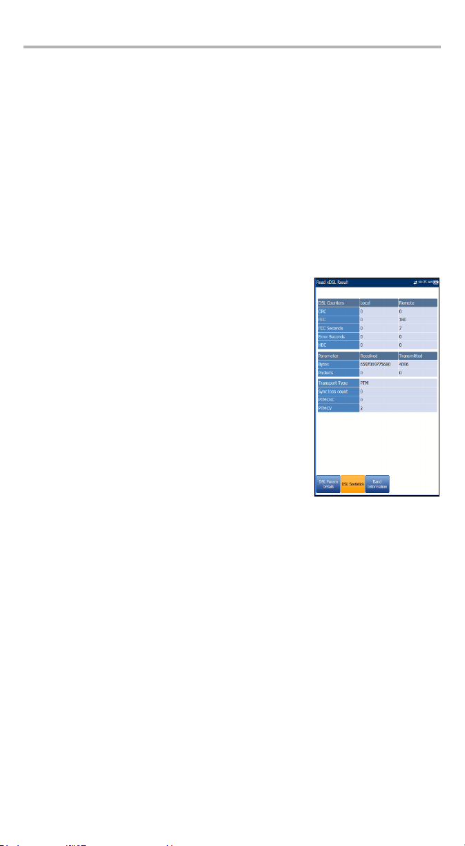
DSL Statistics
The DSL Statistics tab allows you to view transfer mode statistics and DSL counters.
³ DSL Counters lists the Local and Remote results for
the following counters:
³ CRC is the cyclical redundancy check
Interleaved/Fast counter.
³ FEC is the Reed Solomon forward error
correction.
³ FEC Seconds is the number of seconds when FEC
is detected.
³ Error Seconds is the number of seconds when
code violation is detected.
³ HEC is the header error check (HEC)
Interleaved/Fast counter. Available only in ATM
connection mode.
³ Parameter - Received/Transmitted
³ Bytes records the number of active (non-idle) PTM/ATM cells or frames on
a channel.
³ Packe ts displays the number of packets.
³ Transp ort Type options include PTM (packet transfer mode) and ATM
(asynchronous transfer mode).
³ Sync Loss Count is the number of times the unit lost synchronization.
³ PTMCRC is the number of CRC (cyclical redundancy check) errors of the PTM.
³ PTMCV is the number of CV (code violation) errors of the PTM.
Page 39

Band Info
The Band Info tab allows you to view a list of individual upstream or downstream
band parameter details.
³ Band contains Upstream (US) and Downstream (DS)
parameters.
³ ADSL lists only 1 of each.
³ VDSL lists US0 to 3 and DS1 to 3 possible bands,
depending on the band plan,
³ Parameter - Downstream/Upstream
³ SNR Margin is the measured current
signal-to-noise ratio margin across all active
sub-carriers, as an amount of increased noise
relative to the measured noise power that the
system would be able to tolerate. Only a value of 6
or above is able to support a bit error rate of 10
³ Loop Attenuation is the current reduction of the
line and is measured only once during training.
³ Signal Attenuation is the current reduction of the signal and is measured
periodically when the line is connected.
³ Tx Power is the upstream/downstream transmitting power for the
selected band.
³ Output Power is the current transmit power level that is a measure of the
aggregated transmit power.
-7
.
Data Tests Summary
The Data Tests Summary tab displays the pass/fail status
of the selected data tests enabled in the connection setup.
A successful WAN connection must be established in
order to view the detailed results.
To view individual data test results:
1. Press the up/down navigation keys to select the
desired test.
2. Press to display the test result details.
MaxTester DSL 33
Page 40
MaxTester DSL Test Results 34
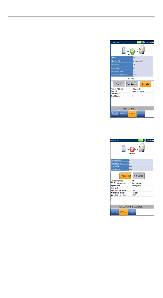
Ping Test
The Ping Test tab allows you to view the Pass/Fail summary status of either a Ping
Address or Ping Gateway.
³ Status is the status of the Ping test performed.
³ Ping IP/URL is the IP Address or domain name of the
destination being pinged.
³ Packe t Size is the number of bytes sent in one packet.
³ Packe ts Sent is the number of packets sent.
³ Packets Received is the number of packets received.
³ Average Round Trip Time is the duration in
milliseconds (ms) it took the data to reach the
destination device and come back.
³ Ping IP Address is the destination IP address.
³ Ping URL is the destination URL address.
³ Packe t Size is the number of bytes sent in one packet
ranging from 32 through 1200 (default is 32 bytes).
³ Tota l P i ng s is the total number of Ping requests to be sent.
FTP Test
The FTP Test tab displays the FTP download and upload
results configured in the connection setup, and a pass/fail
summary status of whether or not the file transfer protocol
(FTP) was completed successfully or not.
Except for Auto Test, FTP parameters can be reconfigured
and have information updated from this tab by using the
on-screen FTP Download/Upload buttons.
Page 41

Traceroute Test
The Trace Route Test tab allows you to view the pass/fail
status of the IP packet sent to a specified IP destination,
and the path and time taken to do so.
Except for Auto Test, Traceroute parameters can be
reconfigured and have information updated from this tab
by using the on-screen Tra ce U RL or Trace IP buttons.
Web Browser
The Web browser results screen is available only if the
software option is enabled. Web browser results
screen contains the following functions:
³ URL Box displays the current Web address to be
connected.
³ The Go button launches the specified URL or reloads
the previous Web page.
³ On-screen function keys:
³ Back retrieves the previous Web page (if
available). If no Web page was previously
browsed, this key is disabled.
³ Enter Text opens the editor screen allowing you
to type an entry.
³ Bookmarks opens the Bookmarks page allowing
you to select a URL from the list or save the current URL to Bookmarks. You
must press to enable the Bookmarks key.
³ Refresh reloads the current Web page.
³ STOP halts loading the Web page. If the Web page has already loaded, the
key is disabled.
³ Forw ard takes you to the next Web page (if available). If no Web page was
browsed after the current page, this key will be disabled.
MaxTester DSL 35
Page 42

MaxTester DSL Test Results 36
To edit the Web address:
1. Pres s t o hi ghlight the URL box.
2. Press to bring up the edit screen and modify the Web address. The edited
URL can be used to browse the Web page temporarily but it will not be saved as
the Home URL.
To navigate the Web browser page:
1. Use the keypad arrow keys to move the on-screen cursor. When the cursor
reaches the edge of the viewing area, the Web browser page scrolls
up/down/left/right. The cursor turns into a text edit tool when scrolling over an
editable field or a hand tool when hovering near a hyperlink.
2. Press to launch the desired outcomes.
3. Press to load the Home URL page.
4. Press to exit from the Web browser test.
Bookmarks
The Bookmarks page allows you to select from a list of
URLs or save the current one.
³ URL box shows the current URL in the Web browser
page.
³ On-screen function keys:
³ Add to Bookmarks copies the current URL to the
Bookmarks list above the highlight. When the list
reaches the maximum 9 URLs, the key is
disabled.
³ Select copies the highlighted URL to the URL box.
³ GO saves the bookmarks and starts the Web
connection using the address in URL box.
Press to exit from the Bookmarks page avoiding all
actions and return to the Web browser page.
Page 43

7 Saving and Reading Test
Results
Save Results
You can save a snapshot of test results into a result file during or after a test
performed with the MaxTester DSL. Each Auto Test, xDSL, and Ethernet test includes
a Save Results tab to do so.
When a test is completed or stopped, a Confirm Save Results dialogue box pops
up. Selecting Yes displays the Save Results screen where the following information
can be entered:
³ File Name opens an editor screen where you can
enter a desired file name.
³ Save button saves the results in binary format for the
test executed.
³ Export Format generates results of a pre-executed
test in the following formats:
³ binary
³ HTML
³ XML
³ Export File Name opens an editor screen where you
can enter a desired export file name.
³ Export button sends the results, in the selected
format, to a USB key. If more than one USB key is
attached to the device, you’ll be asked to select one
from a list of all USB keys attached to the unit.
Note: If the test is still running (not completed or stopped), only the first two
To save or export results:
1. Press the up/down arrows to select the desired parameter.
2. Press the left/right arrow keys to view and select the options,
3. Press to open the on-screen keyboard. to enter or edit a File Name.
4. Press the up/down left/right arrows to navigate the on-screen keyboard.
5. Select the desired function key to complete your selection.
6. Select Save or Export buttons and press to confirm your selection.
MaxTester DSL 37
fields are available and the results are saved to binary format.
Or
Page 44

Saving and Reading Test Results 38
Read Results Menu
You can view any of your saved results with the MaxTester
DSL from the Main Menu and selecting the Read Results
icon. The sub-menu displays an icon for each test: Auto
Test, xDSL, and Ethernet.
To select a test:
1. Press the up/down left/right navigation keys to select
the desired icon.
2. Press to display a list of the saved test results.
Read Results
Based on the selected value for the test type, the list of
result files is displayed by File Name and test date and
time. The format of Te s t D a t e Time is per the selection in
System settings.
When a file in the list is selected and enter key is pressed,
it will read the file and display the result on the GUI.
To recall any of the saved data:
1. Press and select Read Results.
2. Select one of the Read test Results icons.
3. Select a file in the list using the up/down arrow keys.
4. Press to open the file and display the results.
Page 45

8 Maintenance
General Maintenance
To help ensure long, trouble-free operation:
³ Keep the unit free of dust.
³ Clean the unit casing and front panel with a cloth slightly dampened with water.
³ Store unit at room temperature in a clean and dr y area. Keep the unit out of
direct sunlight.
³ Avoid high humidity or significant temperature fluctuations.
³ Avoid unnecessary shocks and vibrations.
³ If any liquids are spilled on or into the unit, turn off the power immediately and
let the unit dry completely.
MaxTester DSL 39
Page 46

Maintenance 40
Recycling and Disposal (Applies to European Union Only)
Recycle or dispose of your product (including electric and electronic
accessories) properly, in accordance with local regulations. Do not
dispose of it in ordinary garbage receptacles.
This equipment was sold after August 13, 2005 (as identified by the
black rectangle).
³ Unless otherwise noted in a separate agreement between EXFO and a
customer, distributor or commercial partner, EXFO will cover costs related to
the collection, treatment, recovery and disposal of end-of-lifecycle waste
generated by electronic equipment introduced after August 13, 2005 to an
European Union member state with legislation regarding Directive 2002/96/EC.
³ Except for reasons of safety or environmental benefit, equipment manufactured
by EXFO, under its brand name, is generally designed to facilitate dismantling
and reclamation.
For complete recycling/disposal procedures and contact information, visit the EXFO
Web s i t e a t www.exfo.com/recycle.
Page 47

9 Troubleshooting
Ver.
Mfg.
date
P/N
S/N
Made in Canada QST442B
465 Godin Avenue
Vanier (Quebec) G1M 3G7 CANADA
**************** A
January 2020
542392-3D
MAX-630-XX-XX
Model
ADSL version
DSL software options
Contacting the Technical Support Group
To obtain after-sales service or technical support for this product, contact EXFO at
one of the following numbers. The Technical Support Group is available to take your
calls from Monday to Friday, 8:00 a.m. to 7:00 p.m. (Eastern Time in North America).
For detailed information about technical support, visit the EXFO Web site at
www.exfo.com.
Technical Support Group
400 Godin Avenue
Quebec (Quebec) G1M 2K2
CANADA
To accelerate the process, please have information such as the name and the serial
number (see the product identification label—an example is shown below), as well
as a description of your problem, close at hand.
1 866 683-0155 (USA and Canada)
Tel.: 1 418 683-5498
Fax: 1 418 683-9224
support@exfo.com
Transportation
Maintain a temperature range within specifications when transporting the unit.
Transportation damage can occur from improper handling. The following steps are
recommended to minimize the possibility of damage:
³ Pack the unit in its original packing material when shipping.
³ Avoid high humidity or large temperature fluctuations.
³ Keep the unit out of direct sunlight.
³ Avoid unnecessary shocks and vibrations.
MaxTester DSL 41
Page 48

Warranty 42
10 Warranty
General Information
EXFO Inc. (EXFO) warrants this equipment against defects in material and
workmanship for a period of one year from the date of original shipment. EXFO also
warrants that this equipment will meet applicable specifications under normal use.
During the warranty period, EXFO will, at its discretion, repair, replace, or issue
credit for any defective product, as well as verify and adjust the product free of
charge should the equipment need to be repaired or if the original calibration is
erroneous. If the equipment is sent back for verification of calibration during the
warranty period and found to meet all published specifications, EXFO will charge
standard calibration fees.
IMPORTANT
The warranty can become null and void if:
³ unit has been tampered with, repaired, or worked upon by
unauthorized individuals or non-EXFO personnel.
³ warranty sticker has been removed.
³ case screws, other than those specified in this guide, have been
removed.
³ case has been opened, other than as explained in this guide.
³ unit serial number has been altered, erased, or removed.
³ unit has been misused, neglected, or damaged by accident.
THIS WARRANTY IS IN LIEU OF ALL OTHER WARRANTIES EXPRESSED, IMPLIED,
OR STATUTORY, INCLUDING, BUT NOT LIMITED TO, THE IMPLIED WARRANTIES OF
MERCHANTABILITY AND FITNESS FOR A PARTICULAR PURPOSE. IN NO EVENT
SHALL EXFO BE LIABLE FOR SPECIAL, INCIDENTAL, OR CONSEQUENTIAL
DAMAGES.
Liability
EXFO shall not be liable for damages resulting from the use of the product, nor shall
be responsible for any failure in the performance of other items to which the
product is connected or the operation of any system of which the product may be a
part.
EXFO shall not be liable for damages resulting from improper usage or unauthorized
modification of the product, its accompanying accessories and software.
Page 49

Exclusions
EXFO reserves the right to make changes in the design or construction of any of its
products at any time without incurring obligation to make any changes whatsoever
on units purchased. Accessories, including but not limited to fuses, pilot lamps,
batteries and universal interfaces (EUI) used with EXFO products are not covered by
this warranty.
This warranty excludes failure resulting from: improper use or installation, normal
wear and tear, accident, abuse, neglect, fire, water, lightning or other acts of nature,
causes external to the product or other factors beyond the control of EXFO.
Certification
EXFO certifies that this equipment met its published specifications at the time of
shipment from the factory.
MaxTester DSL 43
Page 50

Warranty 44
Service and Repairs
EXFO commits to providing product service and repair for five years following the
date of purchase.
To send any equipment for service or repair:
1. Call one of EXFO’s authorized service centers (see EXFO Service Centers
Worldwid e on page 45).Support personnel will determine if the equipment
requires service, repair, or calibration.
2. If equipment must be returned to EXFO or an authorized service center, support
personnel will issue aReturn Merchandise Authorization (RMA) number and
provide an address for return.
3. If possible, back up your data before sending the unit for repair.
4. Pack the equipment in its original shipping material. Be sure to include a
statement or report fully detailing the defect and the conditions under which it
was observed.
5. Return the equipment, prepaid, to the address given to you by support
personnel. Be sure to write the RMA number on the shipping slip. EXFO will
refuse and return any package that does not bear anRMA number.
Note: A test setup fee will apply to any returned unit that, after test, is found to
meet the applicable specifications.
After repair, the equipment will be returned with a repair report. If the equipment is
not under warranty, you will be invoiced for the cost appearing on this report. EXFO
will pay return-to-customer shipping costs for equipment under warranty. Shipping
insurance is at your expense.
Routine recalibration is not included in any of the warranty plans. Since
calibrations/verifications are not covered by the basic or extended warranties, you
may elect to purchase FlexCare Calibration/Verification Packages for a definite
period of time. Contact an authorized service center (see EXFO Service Centers
Worldwid e on page 45).
Page 51

EXFO Service Centers Worldwide
If your product requires servicing, contact your nearest authorized service center.
EXFO Headquarters Service Center
400 Godin Avenue
Quebec (Quebec) G1M 2K2
CANADA
EXFO Europe Service Center
Omega Enterprise Park, Electron Way
Chandlers Ford, Hampshire S053 4SE
ENGLAND
EXFO Telecom Equipment
(Shenzhen) Ltd.
3rd Floor, Building 10,
Yu Sheng Industrial Park (Gu Shu Crossing),
No. 467,
National Highway 107,
Xixiang, Bao An District,
Shenzhen, China, 518126
1 866 683-0155 (USA and Canada)
Tel.: 1 418 683-5498
Fax: 1 418 683-9224
quebec.service@exfo.com
Tel.: +44 2380 246810
Fax: +44 2380 246801
europe.service@exfo.com
Tel: +86 (755) 2955 3100
Fax: +86 (755) 2955 3101
beijing.service@exfo.com
MaxTester DSL 45
Page 52

Technical Specifications 46
SPECIFICATIONS
DSL INTERFACE
Chipset Broadcom
Standards Compliance
VDSL2
ADSL1/2/2+
ITU-T G.993.2
Annex A version (over POTS): ITU-T G.992.5 (ADSL2+), ITU-T G.992.3 (ADSL2),
ITU-T G.992.1 (G.DMT) and ANSI T1.413 Issue 2
Annex B version (over ISDN): ITU-T G.992.5 (ADSL2+), ITU-T G.992.3 (ADSL2),
ITU-T G.992.1 (G.DMT)
Annex L (RE-ADSL) and Annex M (optional) also supported
DSL measurements (upstream and downstream) Maximum attainable bit rates
Actual achieved bit rates
Latency mode: fast, interleaved
Capacity (%)
Signal-to-noise ratio (SNR) margin
Output power
Attenuation
Carrier load (bits/bin)
Interleave depth
Interleave delay
Trellis coding
Bit swapping
Miscellaneous functions PhyR™ and INP support
Nitro™ support
FEC, CRC, HEC counters
Loss of sync counter
VDSL2 per band information
DATA TESTING
Interfaces supported VDSL2
ADSL1/2/2+
Ethernet 10/100
Encapsulation methods
PPPoE (RFC 2516), RFC 2684 supporting bridged Ethernet (IPoE), IPoA (RFC 1577),
PPPoA/LLC and PPPoA/VC-MUX (RFC 2364)
Operating modes DSL Terminate
Modem Replacement (DSL to Ethernet) Pass Through
Ethernet Terminate
Ethernet/Ethernet Pass Through
Login format Username and password using PAP/CHAP
IP connectivity support DNS, DHCP client/server, NAT, VLAN
IP ping Pings another device on the network
Ping destination: gateway, IP address or URL
Number of pings: 1 to 99
Packet size: 32 to 1200 bytes (32 is default)
Timeout: 1 to 10 seconds
Results: packets sent/received, average round-trip delay (ms)
A Technical Specifications
IMPORTANT
The following technical specifications can change without notice.
The information presented in this section is provided as a reference
only. To obtain this product’s most recent technical specifications,
visit the EXFO Web site at.
Page 53

SPECIFICATIONS (continued)
Traceroute Determines the path used to reach a device on the network
Timeout: In seconds, default is 1 s, maximum is 10 s
Packet size: 32 bytes
Number of hops: 1 to 32 (default is 30)
Results: Indicate IP address of hop and round-trip time in milliseconds (ms)
FTP speed test Displays speed to upload and/or download a file
Address: IP or URL
Protocol: FTP
Results: Time, kB transferred, speed in kbit/s
WEB BROWSER
Internet live feed
Browses to websites over xDSL or Ethernet interfaces; user-definable bookmarks
IPTV TESTING
Interfaces supported VDSL2, ADSL1/2/2+, Ethernet 10/100
Supported video standards MPEG2, MPEG4 part 2 and 10 (H.264/AVC), WM9
Operating modes
DSL Terminate
Ethernet Terminate
IPTV parameters/functionality
IGMP join/leave requests with STB emulation
Automatic tests to join/leave and analyze up to five simultaneous streams
Programmable channel list for storage of commonly used channels
Bandwidth usage per channel
IGMP packet and rate information per line and channel
Multicast/unicast RTP/UDP IP stream support
Key IP video QoS parameters Packet loss, zap time, PID statistics
Graphical results Transport stream packet loss histogram
Pass/fail indication for each stream
MaxTester DSL 47
Page 54
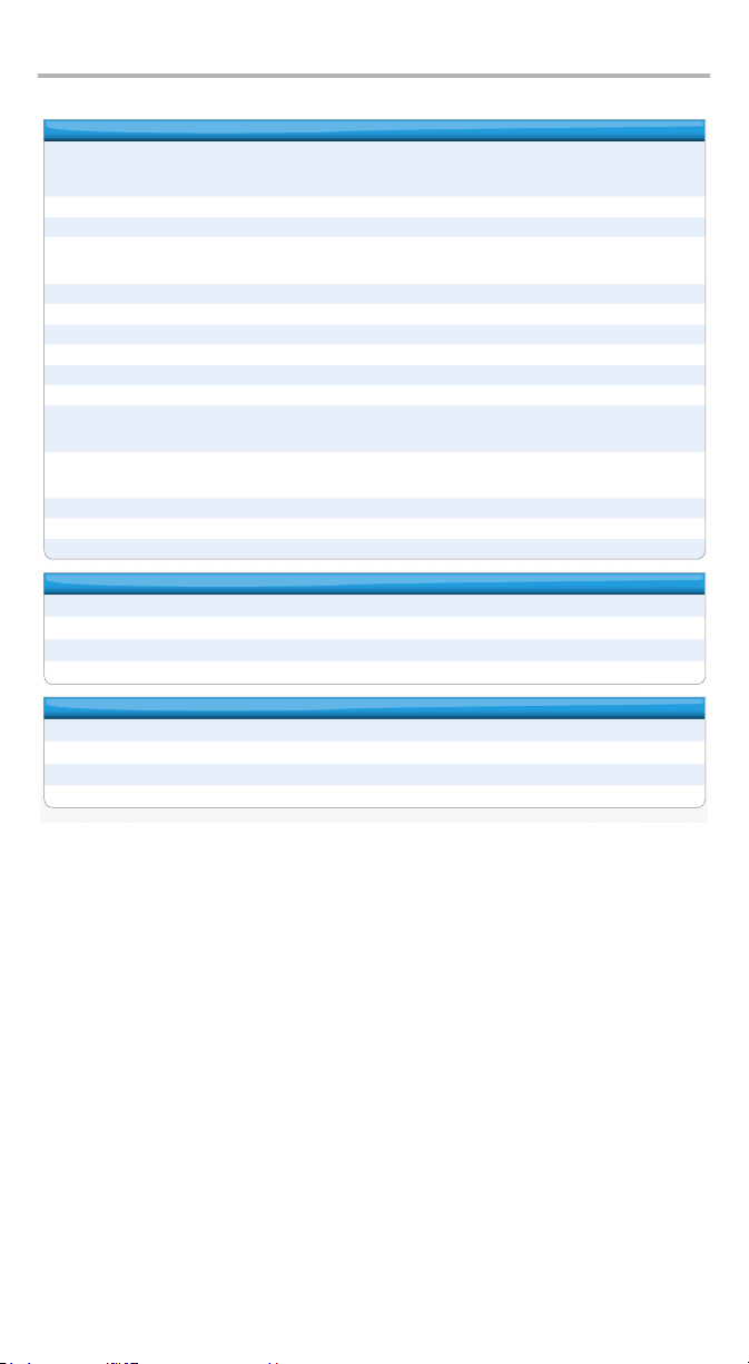
Technical Specifications 48
GENERAL SPECIFICATIONS
Display TFT LCD with backlight
152 mm (6 in) diagonal
800 x 480 resolution, WVGA
Size (H x W x D) 254 mm x 124 mm x 62 mm (10 in x 4 7/8 in x 2 7/16 in)
Weight (with battery) 1.5 kg (3.3 lb)
Temperature range
operating
storage
0 °C to 40 °C (32 °F to 104 °F)
–20 °C to 60 °C (–4 °F to 140 °F)
Humidity 5 % to 95 % relative, non-condensing
Shock 1 m (39 in) drop per GR-196-CORE
Water/dust ingress Designed to comply with IP54
Altitude 3000 m (9842 ft)
Input power 9 V to 24 V DC up to 1.67 A, minimum 15 W
Battery Internal rechargeable Lithium, with battery-state and level indications through the software
Test connections
RJ-11 for ADSL2+/VDSL2
RJ-45 for Ethernet 10/100 WAN
RJ-45 for Ethernet 10/100 LAN
Connectivity
USB 2.0 ports
Three clients: Type A connectors
One host: Type B connector
Results storage 1.2 GB internal memory
Languages English, French, Spanish, Chinese (Simplified)
CE and CSA marked
STANDARD ACCESSORIES
Test cable: RJ-11 to RJ-11 and telco clip with bed of nails (ACC-RJ11-TC), or RJ-11 to RJ-11 and 4 mm plugs with crocodile clips (ACC-RJ11-4MM)
Certificate of compliance
AC adapter (GP-2146)
Soft carrying case (GP-10-061)
OPTIONAL ACCESSORIES
RJ-45 Ethernet cable (ACC-RJRJ-UTP)
USB host/client cable (GP-2053)
12 V vehicle charger (CL4-CAR)
Form fitting, protective soft glove with shoulder strap (ACC-GLOVE)
Page 55

Index
A
AC requirements ..................................................................................................... 8
after-sales service .................................................................................................. 41
C
caution
of personal hazard ................................................................................ 2, 3, 6, 7
of product hazard ............................................................................................. 6
certification information ......................................................................................... v
cleaning
front panel ...................................................................................................... 39
cold shutdown ........................................................................................................ 9
conventions, safety ................................................................................................. 6
current, electrical..................................................................................................... 8
customer service.................................................................................................... 44
E
equipment returns ................................................................................................ 44
EXFO service centers.............................................................................................. 45
F
front panel, cleaning ............................................................................................. 39
I
identification label ................................................................................................ 41
indoor use ............................................................................................................... 8
input current ........................................................................................................... 8
K
keypad .................................................................................................................. 10
L
label, identification ............................................................................................... 41
M
main menu............................................................................................................ 10
maintenance
front panel ...................................................................................................... 39
general information ........................................................................................ 39
maximum input current .......................................................................................... 8
menus ................................................................................................................... 10
MaxTester DSL 49
Page 56

Index 50
P
power source, AC .................................................................................................... 8
product
identification label .......................................................................................... 41
specifications .................................................................................................. 46
R
return merchandise authorization (RMA) .............................................................. 44
S
safety
caution.............................................................................................................. 6
conventions ...................................................................................................... 6
warning ................................................................................................ 2, 3, 6, 7
service and repairs................................................................................................. 44
service centers ....................................................................................................... 45
shipping to EXFO................................................................................................... 44
shut down
cold vs. warm.................................................................................................... 9
unit ................................................................................................................... 9
specifications, product .......................................................................................... 46
storage requirements ............................................................................................ 39
symbols, safety........................................................................................................ 6
T
technical specifications.......................................................................................... 46
technical support .................................................................................................. 41
temperature for storage ........................................................................................ 39
transportation requirements ........................................................................... 39, 41
U
unit shutting down ................................................................................................. 9
W
warm shutdown...................................................................................................... 9
warranty
certification..................................................................................................... 43
exclusions........................................................................................................ 43
general............................................................................................................ 42
liability ............................................................................................................ 42
null and void ................................................................................................... 42
Page 57
NOTICE
抩⛙
CHINESE REGULATION ON RESTRICTION OF HAZARDOUS SUBSTANCES
NAMES AND CONTENTS OF THE TOXIC OR HAZARDOUS SUBSTANCES OR ELEMENTS
▔⚺⦷㦻 EXFO ℶ❐₼䤓㦘㹡㦘⹂䓸德㒥⏒侯䤓⚜䱿✛⚺摞
Indicates that this toxic or hazardous substance contained in all of the homogeneous
materials for this part is below the limit requirement in SJ/T11363-2006
O
嫷䯉年㦘㹡㦘⹂䓸德⦷年捷ↅ㓏㦘⧖德㧟㠨₼䤓⚺摞⧖⦷ SJ/T11363-2006 㪖屓⸩䤓棟摞尐
㻑ⅴₚᇭ
Indicates that this toxic or hazardous substance contained in at least one of the
homogeneous materials used for this part is above the limit requirement in SJ/T11363-2006
X
嫷䯉年㦘㹡㦘⹂䓸德咂⺠⦷年捷ↅ䤓㩟⧖德㧟㠨₼䤓⚺摞怔⒉ SJ/T11363-2006 㪖屓⸩䤓
棟摞尐㻑ᇭ
Par t Na me
捷ↅ⚜䱿
Enclosure
⮥⮂
Electronic and
electrical
sub-assembly
䟄✛䟄兓ↅ
Optical
sub-assembly
⏘ⷵ兓ↅ
Mechanical
sub-assembly
㧉㬿兓ↅ
a. If applicable.
Ⱁ㨫抑䞷ᇭ
a
a
a
a
₼⦌␂ℝ☀⹂䓸德棟Ⓟ䤓屓⸩
CONTAINED IN THIS EXFO PRODUCT
Toxic or hazardous Substances and Elements
Cadmium
Mercury
Lead
㻭
杔
(Hg)
(Pb)
OO O O O O
XO X O X X
XO O O O O
OO O O O O
MARKING REQUIREMENTS
㦘㹡㦘⹂䓸德✛⏒侯
Hexavalent
Chromium
椣
(Cd)
㪖㽷尐㻑
⏼ↆ杻
(Cr VI)
Pol yb ro mi na te d
biphenyls
⮩䅃勣啾
(PBB)
Pol yb r om in at ed
diphenyl ethers
⮩䅃ℛ啾搩
(PBDE)
Pro duct
ℶ❐
This Exfo product
㦻 EXFO ℶ❐
Battery
䟄㻯
a. If applicable.
Ⱁ㨫抑䞷ᇭ
Environmental protection use period (years)
䘾⬒≬㔳∎䞷㦮棟 ( )
10
a
a
5
Logo
㪖㉦
Page 58

P/N:1060868
www.EXFO.com · info@exfo.com
CORPORATE
HEADQUARTERS
EXFO AMERICA 3701 Plano Parkway,
EXFO EUROPE Omega Enterprise Park,
EXFO ASIA-PACIFIC 100 Beach Road,
EXFO CHINA Room 2711, Trade Center,
EXFO SERVICE
ASSURANCE
TOLL-FREE (USA and Canada) 1 800 663-3936
© 2011 EXFO Inc. All rights reserved.
Printed in Canada (2011-03)
400 Godin Avenue Quebec (Quebec) G1M 2K2 CANADA
Suite 160
Electron Way
#22-01/03 Shaw Tower
No. 4028 Jintian Road,
Futian District
Beijing Global Trade Center,
Tower C, Room 1207,
36 North Third Ring Road
East, Dongcheng District
270 Billerica Road Chelmsford MA, 01824 USA
Tel.: 1 418 683-0211 · Fax: 1 418 683-2170
Plano TX, 75075 USA
Tel.: 1 972 907-1505 · Fax: 1 972 836-0164
Chandlers Ford, Hampshire S053 4SE ENGLAND
Tel.: +44 2380 246810 · Fax: +44 2380 246801
SINGAPORE 189702
Tel.: +6563338241 · Fax: +6563338242
Shenzhen 518035 P. R. CHINA
Tel.: +86 (755) 8203 2300
Fax: +86 (755) 8203 2306
Beijing 100013 P. R. CHINA
Tel.: +86 (10) 5825 7755
Fax: +86 (10) 5825 7722
Tel.: 1 978 367-5600 · Fax: 1 978 367-5700
 Loading...