

Page 1
BV10
Performance Endpoint Unit
User Guide
Page 2

Copyright © 2010–2014 EXFO Inc. All rights reserved. No part of this
publication may be reproduced, stored in a retrieval system or transmitted
in any form, be it electronically, mechanically, or by any other means such
as photocopying, recording or otherwise, without the prior written
permission of EXFO Inc. (EXFO).
Information provided by EXFO is believed to be accurate and reliable.
However, no responsibility is assumed by EXFO for its use nor for any
infringements of patents or other rights of third parties that may result from
its use. No license is granted by implication or otherwise under any patent
rights of EXFO.
EXFO’s Commerce And Government Entities (CAGE) code under the North
Atlantic Treaty Organization (NATO) is 0L8C3.
The information contained in this publication is subject to change without
notice.
Trademarks
EXFO’s trademarks have been identified as such. However, the presence
or absence of such identification does not affect the legal status of any
trademark.
Units of Measurement
Units of measurement in this publication conform to SI standards and
practices.
December 4, 2014
Version number:
ii BV10
3.
0.0.1
Page 3

Certification Information
Certification Information
North America Regulatory Statement
This unit was certified by an agency approved in both Canada and the
United States of America. It has been evaluated according to applicable
North American approved standards for product safety for use in Canada
and the United States.
Electronic test and measurement equipment is exempt from FCC part 15,
subpart B compliance in the United States of America and from ICES-003
compliance in Canada. However, EXFO Inc. makes reasonable efforts to
ensure compliance to the applicable standards.
The limits set by these standards are designed to provide reasonable
protection against harmful interference when the equipment is operated in
a commercial environment. This equipment generates, uses, and can
radiate radio frequency energy and, if not installed and used in accordance
with the user guide, may cause harmful interference to radio
communications. Operation of this equipment in a residential area is likely
to cause harmful interference in which case the user will be required to
correct the interference at his own expense.
Modifications not expressly approved by the manufacturer could void the
user's authority to operate the equipment.
European Community Declaration of Conformity
An electronic version of the declaration of conformity for your product is
available on our website at www.exfo.com. Refer to the product’s page on
the Web site for details.
Laser
This product complies with 21 CFR 1040.10 except for deviations pursuant
to Laser Notice No. 50, dated June 24, 2007 and with IEC/EN 60825-1.
BV10-100 and BV10-1000 iii
Page 4

Contents
Certification Information ....................................................................................................... iii
1 Introducing the BV10 ....................................................................................1
Features .................................................................................................................................1
BrixWorx for Turn Up ..............................................................................................................2
Conventions ............................................................................................................................3
2 Safety Information ......................................................................................5
Additional Laser Safety Information .......................................................................................6
Installation Instruction Warnings ............................................................................................7
Other Safety Symbols on Your Unit .........................................................................................8
3 Getting Started .............................................................................................9
Installing the BV10 in a Rack ..................................................................................................9
Connecting the Power ..........................................................................................................10
4 Physical Interfaces, LEDs, and Buttons ......................................................15
BV10 Models .......................................................................................................................15
Port Availability on BV10 .....................................................................................................16
Connecting the TEST Port Interface .......................................................................................16
Connecting the Management Interfaces ...............................................................................18
LEDs .....................................................................................................................................20
RESET and DEFAULT Buttons .................................................................................................21
5 Managing BV10 Verifier on BrixWorx ........................................................23
Configuring BV10 Verifier for BrixWorx Registry ...................................................................23
Configuring a Test .................................................................................................................24
Verifier Health Information ...................................................................................................28
6 Introducing the BV10 CLI ............................................................................29
Command Line Interface .......................................................................................................29
Connecting to the BV10 to a Console ...................................................................................30
Entering Commands .............................................................................................................33
CLI Session ............................................................................................................................37
7 CLI Command Reference ............................................................................39
Conventions ..........................................................................................................................39
Command Availability ...........................................................................................................39
Alphabetical List of CLI Commands .......................................................................................40
Operation Commands ..........................................................................................................42
Configuration Commands ....................................................................................................58
iv BV10
Page 5

8 Test Applications ........................................................................................ 73
Smart Loopback Test .............................................................................................................74
Ping Test ...............................................................................................................................76
TWAMP Light Responder Test ...............................................................................................77
UDP Echo Responder Test .....................................................................................................78
Ethernet OAM Handling Test .................................................................................................79
9 Power Failure Recovery .............................................................................. 81
10 Maintenance ............................................................................................... 83
Cleaning LC Connectors ........................................................................................................84
Recycling and Disposal (Applies to European Union Only) ....................................................84
11 Troubleshooting ......................................................................................... 85
Solving Common Problems ...................................................................................................85
Contacting the Technical Support Group ..............................................................................86
Transportation ......................................................................................................................86
12 Warranty ..................................................................................................... 87
General Information .............................................................................................................87
Liability .................................................................................................................................88
Exclusions .............................................................................................................................89
Certification ..........................................................................................................................89
Service and Repairs ...............................................................................................................90
EXFO Service Centers Worldwide ..........................................................................................91
A Specifications ............................................................................................. 93
General Specifications .........................................................................................................93
Electrical Interface ...............................................................................................................95
Optical Interface ..................................................................................................................95
B Glossary ...................................................................................................... 97
Acronym List ........................................................................................................................97
Ethernet Cables .................................................................................................................102
Index .............................................................................................................. 105
BV10-100 and BV10-1000 v
Page 6

Page 7

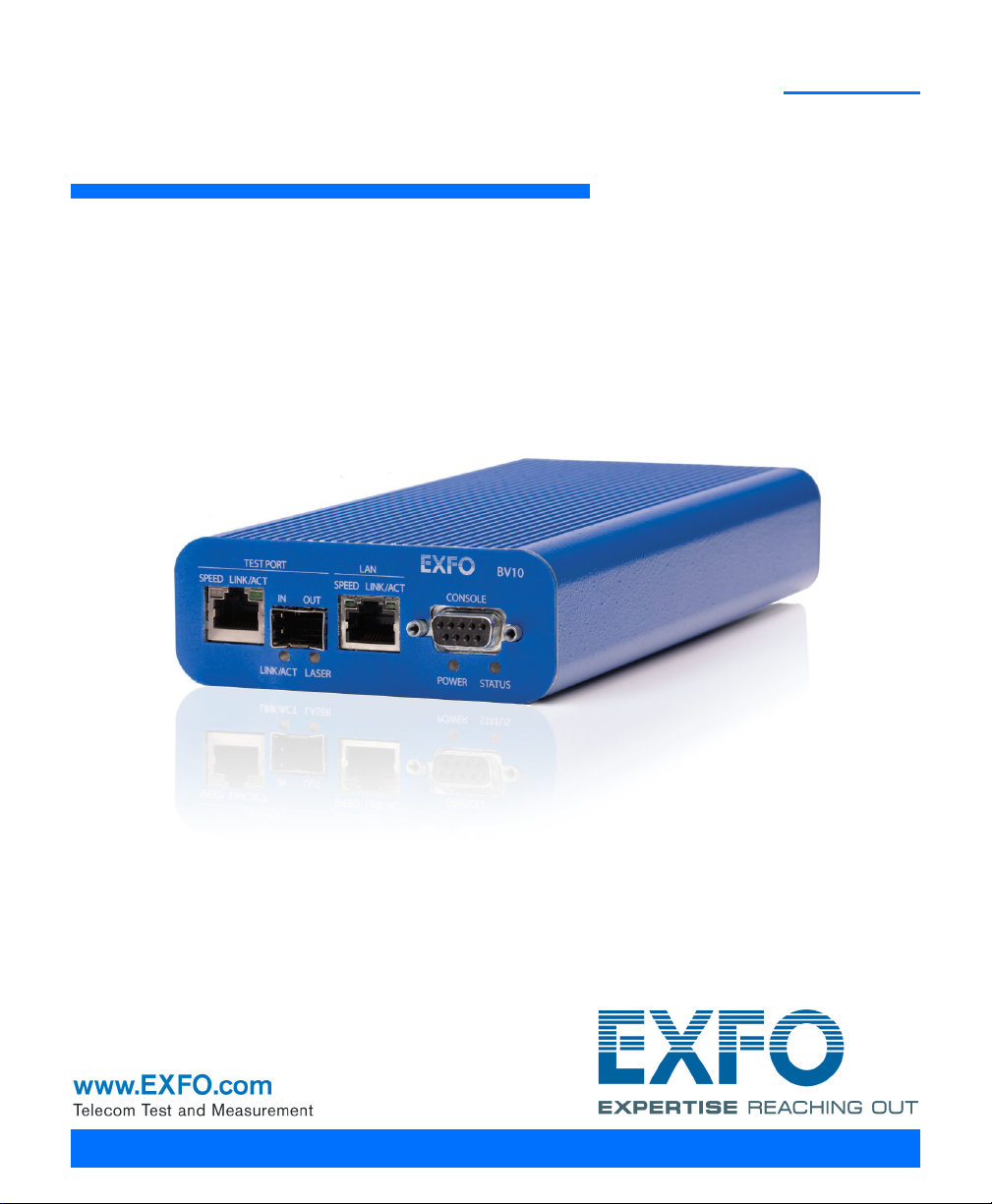
1 Introducing the BV10
Highly cost-effective Ethernet performance monitoring device providing
complete network visibility for mobile backhaul, Carrier Ethernet, and PTN
networks.
Features
Fully integrated in EXFO’s end-to-end mobile backhaul solution for
service turn-up, troubleshooting, and performance monitoring.
Offers complete network visibility at a third of the cost of traditional
Ethernet NID solutions.
Simple and remote management for zero-truck-roll network
maintenance.
Completely standards-based, supporting Ethernet OAM, with 802.1ag
and Y.1731 message response as a performance endpoint, as well as
TWAMP (RFC 5357).
Capability to perform full-line-rate loopback from layer 2 up to layer 4
with rates of 10/100/1000 Mbit/s.
BV10-100 and BV10-1000 1
Page 8

Introducing the BV10
BrixWorx for Turn Up
BrixWorx for Turn Up
BrixWorx for Turn Up is a system designed for Turn-Up and reflector testing
with no monitoring capability. BrixWorx for Turn Up supports a central
management system, Verifier management for the supported Verifier
models, and user management. BrixWorx for Turn Up does not support
active or passive testing.
The BV10 Verifier is designed specifically for Ethernet OAM Handling, UDP
Echo Responder, TWAMP Light Responder, and Smart Loopback test
features. These features are enabled by loading the tests on the Verifier
Information page (Additional Services section) and in some cases
specifying parameters, such as a UDP Listening port for TWAMP or the
mode for Smart Loopback.
For more information, refer to the BrixWorx for Turn Up Getting Started
guide to learn more about the features of the BrixWorx for Turn Up system
and the BrixWorx User Guide to learn more about the Verifier Information
page.
2 BV10
Page 9

Introducing the BV10
Conventions
Before using the product described in this guide, you should understand
the following conventions:
WARNING
Indicates a potentially hazardous situation which, if not avoided,
could result in death or serious injury. Do not proceed unless you
understand and meet the required conditions.
CAUTION
Indicates a potentially hazardous situation which, if not avoided,
may result in minor or moderate injury. Do not proceed unless you
understand and meet the required conditions.
CAUTION
Indicates a potentially hazardous situation which, if not avoided,
may result in component damage. Do not proceed unless you
understand and meet the required conditions.
Conventions
IMPORTANT
Refers to information about this product you should not overlook.
BV10-100 and BV10-1000 3
Page 10

Page 11

2 Safety Information
WARNING
Do not install or terminate fibers while a light source is active.
Never look directly into a live fiber and ensure that your eyes are
protected at all times.
WARNING
The use of controls, adjustments and procedures, namely for
operation and maintenance, other than those specified herein may
result in hazardous radiation exposure or impair the protection
provided by this unit.
IMPORTANT
When you see the following symbol on your unit , make sure
that you refer to the instructions provided in your user
documentation. Ensure that you understand and meet the required
conditions before using your product.
IMPORTANT
Other safety instructions relevant for your product are located
throughout this documentation, depending on the action to
perform. Make sure to read them carefully when they apply to your
situation.
BV10-100 and BV10-1000 5
Page 12
Safety Information
Additional Laser Safety Information
Additional Laser Safety Information
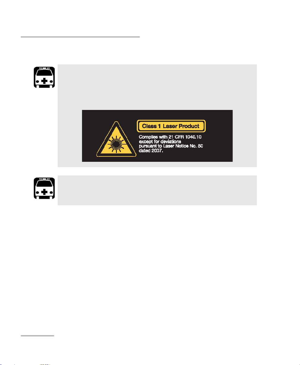
This product employs Class 1 Laser SFP. Invisible laser radiation may
be encountered at the output port. The laser classification is
reproduced on the pluggable transceiver or in its documentation.
When the LASER LED is on or flashing, the BV10 is transmitting an
optical signal on the SFP transceiver port.
WARNING
WARNING
6 BV10
Page 13

Safety Information
Installation Instruction Warnings
Installation Instruction Warnings
CAUTION
No user serviceable parts are contained inside. Contact the
manufacturer regarding service of this equipment.
IMPORTANT
All wiring and installation must be in accordance with local building
and electrical codes acceptable to the authorities in the countries
where the equipment is installed and used.
CAUTION
Electrostatic Discharge (ESD) Sensitive Equipment:
Units can be damaged by static electrical discharge. To minimize the
risk of damage, dissipate static electricity by touching a grounded
unpainted metal object
before removing, inserting, or handling the unit.
before connecting or disconnecting cables to/from the unit.
before inserting or removing SFP transceiver to/from the unit.
CAUTION
For DC version, the BV10 must be installed in Restricted Access
Locations.
IMPORTANT
Unauthorized modifications to this equipment shall void the user’s
authority to operate this equipment.
BV10-100 and BV10-1000 7
Page 14
Safety Information
Other Safety Symbols on Your Unit
Other Safety Symbols on Your Unit
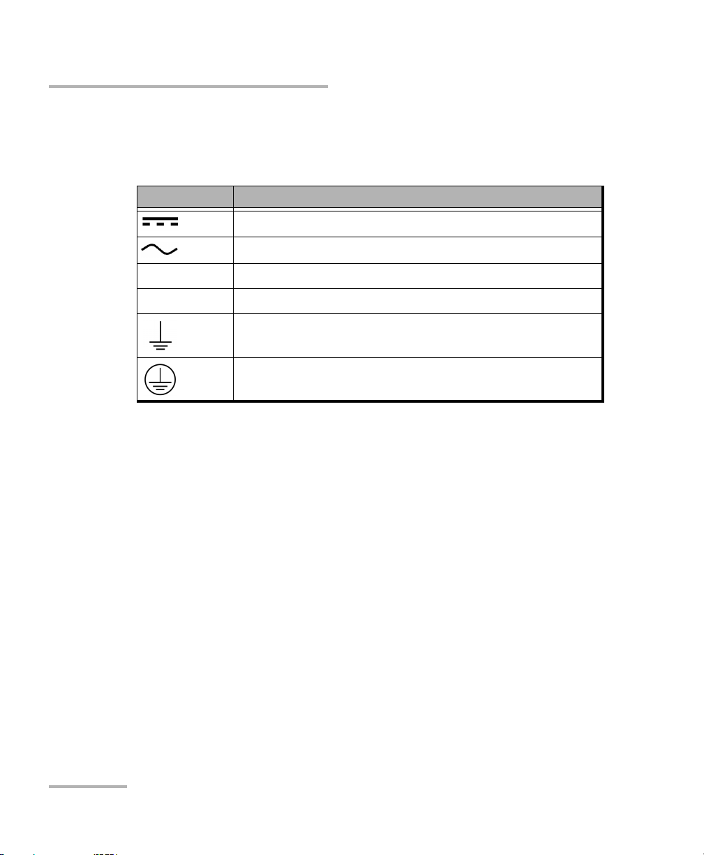
One or more of the following symbols may also appear on your unit.
Symbol Meaning
Direct current.
Alternating current.
+
–
Plus; positive polarity.
Minus, negative polarity.
The unit is equipped with an earth (ground) terminal.
The unit is equipped with a protective conductor terminal.
8 BV10
Page 15
3 Getting Started
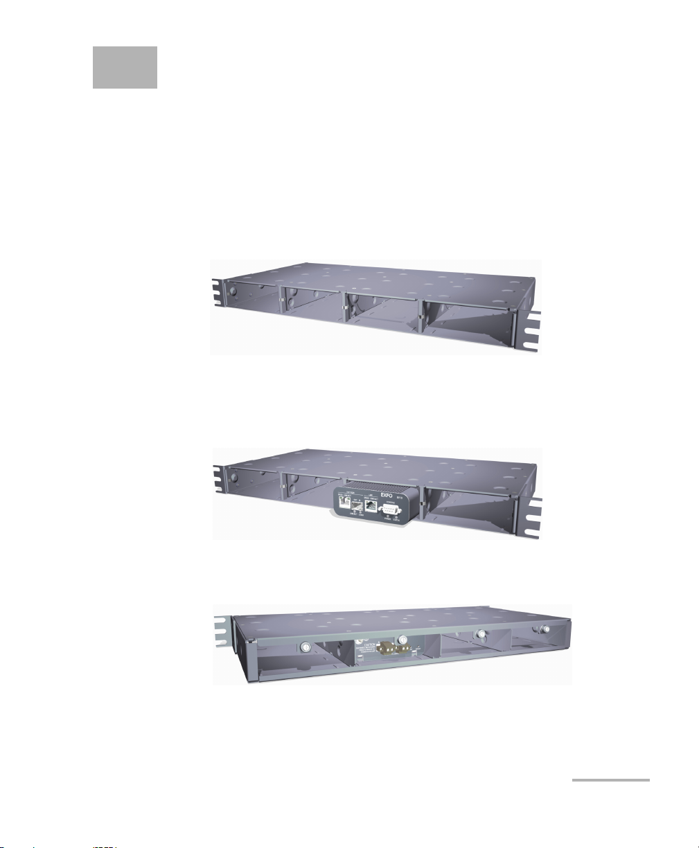
Installing the BV10 in a Rack
The BV10 can be mounted in a rack using the rack mount accessory kit
(ordered separately). The accessory kit shelf holds up to four BV10.
To install the BV10 in a rack:
1. Attach the brackets of the supplied shelf unit to your rack using the
supplied screws.
2. If cables have been attached to the BV10, disconnect all of them as
well as the ground lug from the unit.
3. Slide the unit into the desired slot from front to back.
4. With the unit completely inserted into the slot, tighten the thumb screw
at the back of the unit.
5. Connect all cables and the ground lug, as explained in the next
sections.
BV10-100 and BV10-1000 9
Page 16

Getting Started
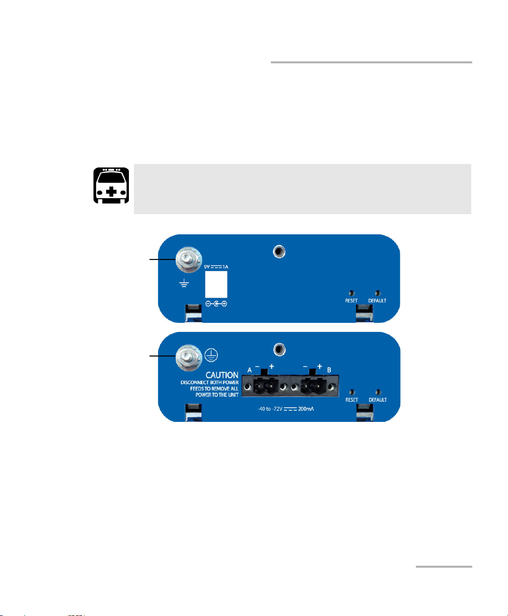
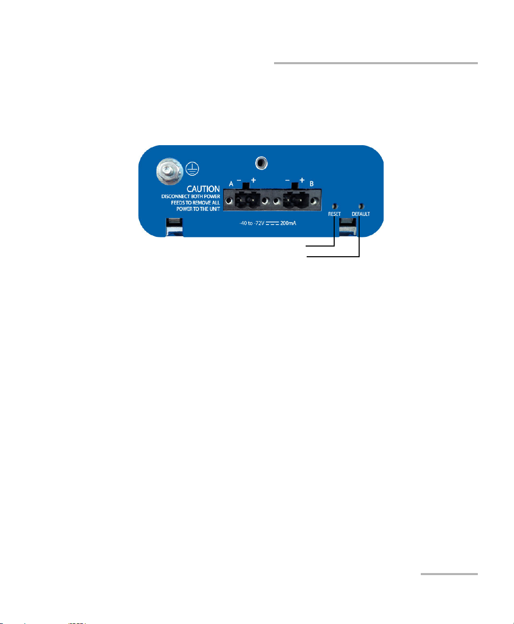
Connecting the Power
Connecting the Power
The BV10 is available with either an AC power supply, DC +24 V connector,
or DC –48 V connector.
As soon as the BV10 is connected to a live power supply, the POWER LED
turns on. If the POWER LED does not turn on, there is a power failure at the
source or the unit is damaged. The STATUS LED indicates whether or not
the unit is ready for use. If the STATUS LED is off the unit is booting up. If it
is green or red the unit has booted (refer to STATUS on page 20).
10 BV10
Page 17
Getting Started
AC unit ground
lug and hardware
DC unit ground
lug and hardware
Connecting the Power
Grounding the BV10
The BV10 is equipped with a ground lug and hardware attached to the
back of the unit. The grounding hardware consists of a washer with
external teeth facing the unit and a locking nut. You will need to supply a
#12 AWG wire.
WARNING
The BV10 DC version is intended to be grounded. Ensure that the unit is
connected to earth ground during normal use.
To ground the BV10:
1. Loosen the locking nut on the grounding lug.
2. Using a #12 AWG wire, twist the wire around the lug so that it is
touching the flat surface of the washer. The wire must be twisted
between the washer and the locking nut.
3. Tighten the locking nut.
4. Connect the other end of the wire to the ground distribution network.
BV10-100 and BV10-1000 11
Page 18

Getting Started
Connecting the Power
Connecting the BV10 using an AC/DC Power
Source
The typical output voltage of the external brick AC power supply is 9 V DC.
To connect the BV10 to an AC power source:
1. Connect the supplied AC power cord to the AC/DC adapter and the
other end to an AC wall outlet.
2. Connect the other end of the power supply to the DC barrel power
connector on the BV10.
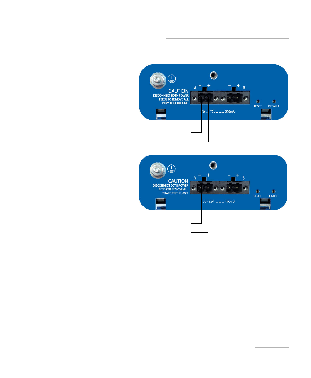
Connecting the BV10 using a DC Power Source
The BV10 DC version is equipped with either +24 V DC or –48 V DC
connector.
Powering a BV10 +24 V DC unit with a –48 V power source will
permanently damage the unit. The +24 V input range is 20-32 V.
WARNING
Powering a BV10 –48 V DC unit with a +24 V power source will
permanently damage the unit. The –48 V input range is –40 to –72 V.
To connect the BV10 to a DC power source:
1. Using 14-16 AWG copper insulated wires and the supplied connector,
insert the two stripped wires into the connector and tighten the screws
firmly. Either use non-stranded wire or crimp a ferrule onto the wire.
Be sure to respect the polarity.
The positive supply wire lead must be on the right side of the
connector and the negative supply wire on the left side.
12 BV10
Page 19
Getting Started
–48 V DC Unit
Supplied connector
Negative (
–) supply wire lead on the left
Positive (+) supply wire lead on the right
+24 V DC Unit
Supplied connector
Negative (
–) supply wire lead on the left
Positive (+) supply wire lead on the right
Connecting the Power
The following figures show the –48 V and +24 V DC units.
-
-
2. Connect the plug to one of the two DC input connectors on the BV10
unit and tighten the screws firmly.
BV10-100 and BV10-1000 13
Page 20

Getting Started
Connecting the Power
3. Connect the other end of the wires to the DC power source.
The DC input feeds to the equipment must be protected by 20 A rated
maximum breaker provided as part of the building installation.
Permanently connected equipment must have a switch or
circuit-breaker for disconnection. If the switch is not part of the kit:
Include a switch or circuit-breaker in the installation.
The switch must be located easily, and placed near the equipment.
The switch must be specified as the disconnecting device for the
4. To add a redundant DC power source on the BV10, repeat step 1
through step 3.
To avoid serious injuries as well as irreparable damages to your unit,
ALWAYS TURN OFF BOTH DISCONNECT DEVICES BEFORE OPENING OR
SERVICING THE UNIT.
CAUTION
equipment.
WARNING
14 BV10
Page 21
4 Physical Interfaces, LEDs, and
LANTEST
CONSOLE
LANTEST
CONSOLE
Laser radiation emitted from this port when LASER LED is on.
Buttons
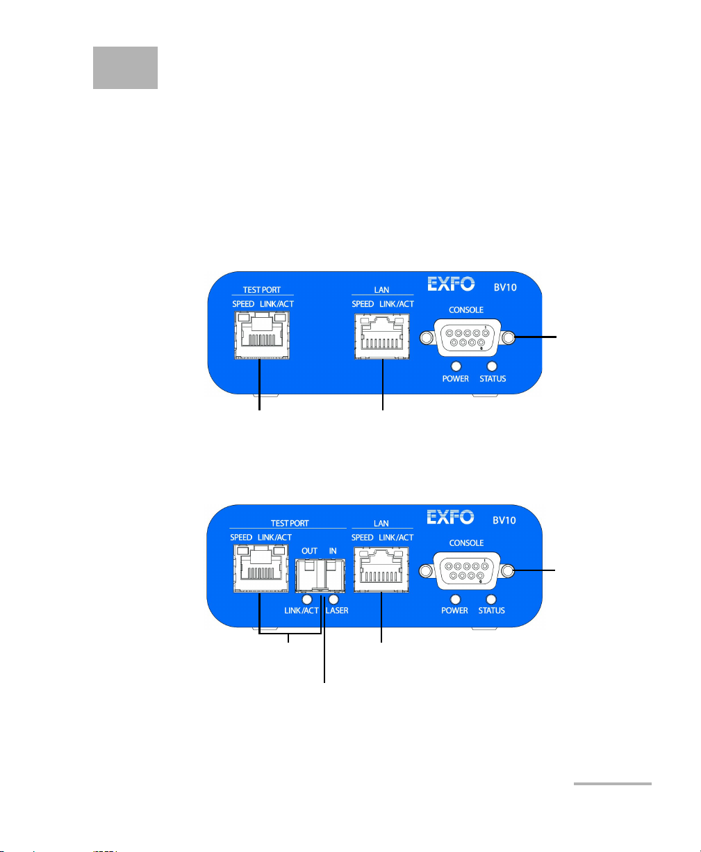
This section describes all connectors (ports), LEDs, and buttons available
on the BV10-100 and BV10-1000 units.
BV10 Models
BV10-100
BV10-1000
BV10-100 and BV10-1000 15
Page 22

Physical Interfaces, LEDs, and Buttons
Port Availability on BV10
Port Availability on BV10
Port
Label
TEST PORT 10/100 Mbit/s electrical RJ45 Test port (10Base-T and 100Base-TX) X
10/100/1000Mbit/s electrical RJ45 Test port (10Base-T, 100Base-TX
and 1000Base-T)
1000 Mbit/s optical SFP Test port (1000Base-SX/LX/ZX;
850/1310/1550nm)
LAN 10/100 Mbit/s electrical Management port X X
CONSOLE RS-232 DE-9F DCE (referred as DB9) Console port X X
Description
BV10-100 BV10-1000
Model
Connecting the TEST Port Interface
The BV10-100 provides an electrical 10/100 Mbit/s Ethernet Test interface
while the BV10-1000 provides an electrical 10/100/1000 Mbit/s and an
optical 1000 Mbit/s SFP laser Ethernet Test interfaces. The two BV10-1000
Test interfaces are mutually exclusive.
RJ45 Port
Connect the 10/100/1000 Mbit/s electrical interface to be tested to the RJ45
test port. The electrical ports is RJ45 for category 5 unshielded twisted pair
(UTP). Refer to Ethernet Cables on page 102 for cable specifications.
X
X
Supported electrical rates are:
For BV10-100: 10 Mbit/s and 100 Mbit/s.
For BV10-1000: 10 Mbit/s, 100 Mbit/s, and 1000 Mbit/s.
16 BV10
Page 23

Physical Interfaces, LEDs, and Buttons
Connecting the TEST Port Interface
SFP Port (BV10-1000)
The BV10-1000 provides an optional optical port for 1000Base-SX/LX/ZX
testing capability. The optical port is a Small Form Factor Pluggable (SFP)
slot type with LC connector.
Insert an SFP module into the SFP test port slot on the BV10. Refer to
Optical Interface on page 95 for more information on supported SFP.
Carefully connect optical fibre cables to the SFP’s IN and OUT ports. To
ensure good signal quality, make sure that the optical fibre connector is
fully inserted into the optical connector port.
CAUTION
To prevent exceeding the maximum input power level please use an
attenuator when a loopback configuration is used.
BV10-100 and BV10-1000 17
Page 24

Physical Interfaces, LEDs, and Buttons
Connecting the Management Interfaces
Connecting the Management Interfaces
The management interface can be connected locally using the CONSOLE
port or remotely using the LAN Port.
LAN Port
Connecting a typical management network to the 10/100 Mbit/s Ethernet
LAN port provides remote access to the BV10 Command Line Interface
(CLI) using either Telnet or SSH session.
To connect remotely to the BV10 using the LAN port, connect both the
BV10 LAN port and the remote PC to the same Management network using
a standard straight through Ethernet cable with RJ45 connectors.
18 BV10
Page 25
Physical Interfaces, LEDs, and Buttons
Connecting the Management Interfaces
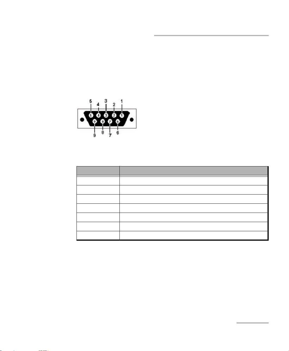
CONSOLE Port
Connecting a PC to the CONSOLE port provides local access to the BV10
using CLI commands.
The following figure shows the DB9 (RS-232 DE-9F DCE) pinouts as viewed
from the front of the BV10.
The following table indicates the DB9 pinouts.
Pin Number Description
1, 4, and 6 Connected together inside the BV10
7 and 8 Connected together inside the BV10
5 Signal ground
2 TX (output of the BV10)
3 RX (input of the BV10)
9 Not internally connected
DB9 casing Chassis ground
To connect locally, connect a PC to the CONSOLE port using an RS-232
straight cable with a DB9 connector.
BV10-100 and BV10-1000 19
Page 26

Physical Interfaces, LEDs, and Buttons
LEDs
LEDs
POWER
On (Green) indicates that the BV10 unit is receiving power from an
external source.
Off indicates that the BV10 unit is not receiving power from the
external source or the unit is damaged.
STATUS
On (Green) indicates that the link on the test port is up.
On (Red) indicates that the link on the test port is down.
Off indicates that the unit is not yet booted.
SPEED
Off indicates 10 Mbit/s
On (Green) indicates 100 Mbit/s
On (Amber) indicates 1000 Mbit/s (BV10-1000 only)
LINK/ACT (Electrical and Optical Ports)
On (Green) indicates that the link is up; there is no activity.
Off indicates that the link is down; there is no activity.
Blinking (Green) indicates that the link is up; there is activity.
LASER
Off indicates that the laser is off.
On (Red) indicates that the laser is on.
20 BV10
Page 27
Physical Interfaces, LEDs, and Buttons
RESET
DEFAULT
RESET and DEFAULT Buttons
RESET and DEFAULT Buttons
The RESET and DEFAULT buttons are recessed on the back of the BV10 to
avoid accidental use.
-
RESET Button
The RESET button is used to reboot the BV10. Press the RESET button once
to reboot the BV10. While rebooting, the BV10 displays a series of
messages if the unit is connected to a console.
The reboot command can also be used to reboot the BV10 (refer to reboot
on page 45).
DEFAULT Button
The DEFAULT button is used to reset the BV10 to the factory default
settings. Press the DEFAULT button once to reset the BV10 to its factory
default settings then the unit reboots by itself.
BV10-100 and BV10-1000 21
Page 28

Page 29

5 Managing BV10 Verifier on
BrixWorx
This chapter describes how to configure and use BV10 hardware on
BrixWorx. It explains the CLI commands used to communicate with the
BrixWorx registry and describes how to set up tests using the BrixWorx
user interface.
Note: When the BV10 is used in a BrixWorx environment, you must use BrixWorx
GUI rather than CLI prompt to manage the BV10 device. When you change
a reflector to run or not through the CLI, this is not updated on the BrixWorx
GUI Additional Services page. The GUI changes override the changes done
using the CLI prompt.
Configuring BV10 Verifier for BrixWorx Registry
The BV10 Verifier must be configured before you can use it in the BrixWorx
system. Once the configuration of a BV10 Verifier is complete, you must
add it to BrixWorx just like any other Verifier.
Configure the BV10 Verifier
To configure the BV10 Verifier for use in the BrixWorx system:
1. Access the CLI prompt using Telnet or SSH. To log on to the Telnet or
SSH server, use the following login information:
Login ID:
Password: exfo123
The CLI prompt name contains the BV10 model number followed by
(DEBUG). For example:
BV10-1000 (DEBUG)>
2. To configure the IP address of the local BrixWorx registry, type the
following command:
BV10-1000 (DEBUG)> server discovery local IP address
BV10-100 and BV10-1000 23
exfo
Page 30

Managing BV10 Verifier on BrixWorx
Configuring a Test
3. To configure the port of communication, type the following command:
BV10-1000 (DEBUG)> server discovery port value
The default port value is 80.
4. To save the new port value, type the following command:
BV10-1000 (DEBUG)> server discovery write
Add the BV10 to BrixWorx
Once you have configured a BV10, you must add it to BrixWorx.
Refer to the BrixWorx User Guide for more information on how to add the
BV10 Verifier to the BrixWorx system.
Configuring a Test
Only a specific set of BrixWorx tests are supported by the BV10 Verifier. All
tests supported on the BV10 Verifier are available through BrixWorx:
Ethernet OAM Handling
UDP Echo Responder
TWAMP Light Responder
Smart Loopback
SSH service
Teln e t ser vi c e
Refer to Test Applications on page 73 for more information on the tests
supported on the BV10 Verifier.
24 BV10
Page 31

Managing BV10 Verifier on BrixWorx
Configuring a Test
To configure a test on a BV10 Verifier using the BrixWorx
Operations Centre:
1. Login to BrixWorx.
2. Select Verifier s.
BV10-100 and BV10-1000 25
Page 32

Managing BV10 Verifier on BrixWorx
Configuring a Test
3. Click the name of the Verifier on which you want to configure the test.
4. Click the edit button for Additional Services. You can choose to load a
specific test or service on this page.
26 BV10
Page 33

Managing BV10 Verifier on BrixWorx
Configuring a Test
5. Enter the time interval at which you want the BV10 Verifier to report the
health information. See Verifier Health Information on page 28 for
more information.
6. Select Load for the tests that you want to configure on the BV10
Verifier.
For the TWAMP Light Responder test, you must enter the UDP port
value to load the test.
For Smart Loopback test, select Ethernet, Ethernet all unicast, IP,
or UDP-TCP to load the specific test.
Refer to Test Applications on page 73 for more information about the
tests that you can load on the BV10 Verifier.
7. To run the S S H or Te lnet s er v ice , sele c t Run.
The selected tests and services are loaded on the BV10 Verifier.
BV10-100 and BV10-1000 27
Page 34

Managing BV10 Verifier on BrixWorx
Verifier Health Information
Verifier Health Information
The BV10 Verifier runs its health status test based on the interval set in the
Status field in the Additional Services category of the Verifier’s advanced
parameters. It reports results to BrixWorx based on its polling interval. The
following figure shows an example of Verifier health information.
To display the Verifier Health page, select the Verifier Health category on
the Verifier Information page.
See Configure the BV10 Verifier on page 23 for more information on how to
set the interval for Verifier status reporting and refer to the Verifiers chapter
in the BrixWorx User Guide for information on the fields from the Verifier
Health page.
28 BV10
Page 35

6 Introducing the BV10 CLI
This chapter describes the BV10 Ethernet Performance Endpoints
Command Line Interface (CLI), its uses, and its features.
Note: Refer to CLI Command Reference on page 39 for more information on
command definition and syntax.
Command Line Interface
The Command Line Interface (CLI) allows to configure and manage the
operation of the BV10 by sending commands to the BV10 using either the
CONSOLE Port, a Telnet session (LAN or TEST Port), or Secure Shell (SSH)
session (LAN or TEST Port).
Note: Telnet and SSH provide the same functionality except SSH provides a secure
channel. Refer to console telnet|ssh server enable|disable on page 61 for
more information on enabling Telnet or SSH.
BV10-100 and BV10-1000 29
Page 36

Introducing the BV10 CLI
Connecting to the BV10 to a Console
Connecting to the BV10 to a Console
Connect the BV10 to a Console for management through CONSOLE, LAN,
or TEST port.
CONSOLE Port
A console is directly connected to the BV10 (CONSOLE Por t). The
CONSOLE port is always available for CLI use.
To use the CONSOLE port:
1. Ensure that your PC is connected to the BV10‘s CONSOLE port. Refer to
CONSOLE Port on page 19.
2. Use a terminal application to connect with the BV10 through its
CONSOLE port.
2a. Start the terminal application.
2b. Set the connection configuration to 9600bps, 8 data bits, no parity,
1 stop bit (9600/8-N-1).
2c. Establish the connection with the BV10.
30 BV10
Page 37

Introducing the BV10 CLI
Connecting to the BV10 to a Console
LAN Port
A console it connected to the BV10 (LAN port) for remote access through
the network using either Telnet or SSH session.
To use the LAN port:
1. Ensure that both your PC network interface and the BV10‘s LAN port
are connected to the same Management network. Refer to LAN Port on
page 18.
2. On your PC, run a terminal application.
3. Select Telnet or SSH connection type.
The use of Telnet server is enabled by default on the BV10.
The use of SSH server is disabled by default on the BV10 and must be
enabled as well as the password must be defined; refer respectively to
console telnet|ssh server enable|disable on page 61 and password set
password on page 61; the user name is exfo. The CLI supports SSHv2.
Encryption keys are factory generated.
4. Enter the BV10 LAN port IP address and Netmask. Default values are:
IP address: 10.10.10.10
Netmask: 255.255.0
5. Establish the connection with the BV10.
BV10-100 and BV10-1000 31
Page 38

Introducing the BV10 CLI
Connecting to the BV10 to a Console
TEST Port
In-band management activities on the TEST port is provided for basic
configuration and software upgrade tasks in situations where the
Management port is inaccessible.
It is important to note that in-band management through the TEST port
should be performed with low traffic volume so that management
responses have minimal impact on test traffic. With high traffic volume,
management responses might add jitter/latency or dropped packets to
results. When a CLI session is opened on the TEST port, the following
warning message appears:
WARNING: Session opened on the TEST Port. Any action may interfere with traffic.
Not all CLI commands are available on the TEST port.
console in-band enable|disable command controls in-band management on
The
the test port. By default, in-band management on the test port is enabled.
Refer to console in-band enable|disable on page 62 for more information.
To use the TEST port:
1. Ensure that both your PC network interface and the BV10‘s TEST port
are connected to the same Management network. Refer to Connecting
the TEST Port Interface on page 16.
2. On your PC, run a terminal application.
3. Select Telnet or SSH connection type.
The use of Telnet server is enabled by default on the BV10.
The use of SSH server is disabled by default on the BV10 and must be
enabled as well as the password must be defined; refer respectively to
console telnet|ssh server enable|disable on page 61 and password set
password on page 61; the user name is exfo. The CLI supports SSHv2.
Encryption keys are factory generated.
4. Enter the BV10 TEST port IP address and Netmask.
5. Establish the connection with the BV10.
32 BV10
Page 39

Introducing the BV10 CLI
Entering Commands
Entering Commands
Once you have connected to the BV10, you can enter CLI commands at the
command prompt. The CLI command prompt is either
BV10-1000>, depending on the BV10 model you are communicating with.
Basic Command Format
The basic format of a CLI command is:
command parameter,...
Both upper and lower case alphanumeric characters and special
characters, such as the slash (/) and colon (:) are supported. Commands
and parameters are not case sensitive.
You can specify no parameter, one parameter, or multiple parameters
separated with comma.
Abbreviating Commands
BV10-100> or
The CLI allows you to type only as much of a command that it is required to
make it unambiguous. For example,
version
because show is the only keyword that starts with sh and version is the
only keyword that starts with
ve. If it cannot be unambiguously determined,
sh ve is the equivalent of typing show
the CLI displays a list of possible commands and parameters that begin
with the partial keyword.
BV10-100 and BV10-1000 33
Page 40

Introducing the BV10 CLI
Entering Commands
Completing Commands
To submit a CLI command, press the Enter key.
The CLI command completion feature lets you type part of a command
and use the Tab key to complete the remainder of the command. Consider
the following examples.
sh <tab> resolves to show
con <tab> resolves to console
sh <tab> ve <tab> resolves to show version
Command completion works as long as what you have typed is
unambiguous – that is, there are no other CLI commands that start with the
letter or letters you have typed. Typing just
the CLI to distinguish
determined, the CLI displays a list of possible commands and parameters
that begin with the partial keyword.
When the rest of the command can be completed, it appears in its
completed form on the same line when you press the Tab key. If the
command cannot be completed, the possible values appear on the
following line when you press the Tab key.
c, for example, does not allow
console from clear. If it cannot be unambiguously
Tip: You can combine abbreviated commands with command completion
on the same line. For example, if you type
resolves to
sh version. When you then press Enter, the CLI abbreviated
command feature allows it to successfully resolve the
and displays the current software/firmware versions.
version
34 BV10
sh v <tab>, the command
sh and the v to show
Page 41

Introducing the BV10 CLI
Entering Commands
Command Editing Keys
The CLI uses common line editing key sequences, as shown in the
following table.
Key Sequence Result
Enter Executes the command.
Backspace Deletes the character to the left of the cursor’s position.
Delete Deletes the character to the left of the cursor’s position.
Home Moves the cursor to the beginning of the line.
End Moves the cursor to the end of the line.
<right arrow> Moves the cursor to the right one character.
<left arrow> Moves the cursor to the left one character.
Ctrl C Interrupts/cancels the command.
<up arrow> Recalls the most recently entered command; scrolls back through the command history
<down arrow> Scrolls forward through all of the commands that have been recalled using the up
Tab Completes the command or keyword. See Completing Commands on page 34 for more
Ctrl D Deletes the character at the cursor’s position.
Ctrl H Deletes the character to the left of the cursor’s position.
Ctrl I Re-displays the current line, completing the last word in the line.
Ctrl J Executes the command.
Ctrl K Deletes all characters from the cursor’s position to the end of the line.
Ctrl L Re-displays the current line.
Ctrl M Executes the command.
Ctrl N Scrolls forward through all of the commands that have been recalled using Ctrl P or the
Ctrl P Recalls the most recently entered command; scrolls back through the command history
buffer each time you press the up arrow key.
arrow.
information.
Up arrow, one command at a time.
buffer each time you repeat the key sequence.
BV10-100 and BV10-1000 35
Page 42

Introducing the BV10 CLI
Entering Commands
Key Sequence Result
Ctrl U Deletes all characters on the line.
Ctrl W Deletes the previous word.
Ctrl Y Pastes from the clipboard.
Esc B Moves the cursor to the start of the previous word.
Esc C Capitalizes the current character.
Esc D Deletes all characters in a word from the cursor’s position to the end of the word.
Esc F Moves the cursor forward one word at a time.
Esc L Lowercases the current character and those that follow in the current word.
Esc U Uppercases the current character and those that follow in the current word.
Esc Delete Deletes the previous word.
Note: Not all key sequences are available to the SSH client. Because an SSH client
buffers data before sending it to the BV10, line editing keys are interpreted
by the SSH client and not by the CLI shell on the BV10. It might be required
to press Enter after using certain keys, such as Tab and ? for example, to get
the result described in the above table.
Command History
The BV10 CLI stores commands performed during a session in a history
buffer. You can recall most recent commands from the history buffer using
either: Up arrow key, Ctrl P, Down arrow key, and Ctrl N (see above table
for more information).
36 BV10
Page 43

Introducing the BV10 CLI
CLI Session
CLI Session
All commands are available at any time once a communication session
has been established with the BV10.
All commands are executed immediately and any configuration changes
are saved automatically.
Idle Timeout
The BV10 has a security feature, called the idle timeout, that logs users out
of a CLI session and closes the connection if there has been no activity for
a specified period of time. An idle timeout can be set for each type of
access (CONSOLE port, Telnet session, or SSH session). It can also be
disabled.
Refer to console telnet|ssh|serial idle-timeout value_in_seconds on
page 62 for more information on how to configure the timeout period.
In addition to the session timeout, a communication session is
automatically closed when the connection is closed or lost (for a LAN
connection).
BV10-100 and BV10-1000 37
Page 44

Page 45

7 CLI Command Reference
This chapter describes the BV10 command line interface (CLI). The
commands are grouped under Operation and Configuration commands.
Note: When the BV10 is used in a BrixWorx environment, you must use BrixWorx
GUI rather than CLI prompt to manage the BV10 device. When you change
a reflector to run or not through the CLI, this is not updated on the BrixWorx
GUI Additional Services page. The GUI changes override the changes done
using the CLI prompt.
Note: Refer to Introducing the BV10 CLI on page 29 for more information on CLI
and its features.
Conventions
The following table lists the conventions used in this chapter to represent
command syntax.
Convention Description Example
Pipe symbol | Choice between two
or more parameters.
Square brackets [ ] Optional parameters.
Italics Variable information.
all | lan | test
Select one of the keywords:
all, lan or test.
[timeout value_in_ms]
The timeout parameter and its
value_in_ms are optional.
value
size size_in_bytes
Enter a number in place of
size_in_bytes.
Command Availability
All CLI commands can be sent through the LAN and CONSOLE ports. Only
a subset of commands can be sent through the Test port.
BV10-100 and BV10-1000 39
Page 46

CLI Command Reference
Alphabetical List of CLI Commands
Alphabetical List of CLI Commands
The following table lists the BV10 CLI commands in alphabetical order.
?44
clear statistics 50
console in-band enable|disable 62
console in-band port port_value 62
console telnet|ssh|serial idle-timeout value_in_seconds 62
console telnet|ssh server enable|disable 61
eth-oam enable|disable 72
help 43
interface lan duplex auto 65
interface lan duplex half|full 66
interface lan flow auto 66
interface lan flow rx|none 66
interface lan speed 10|100 force 65
interface lan|test address-netmask IP_address/netmask|dhcp 68
interface lan|test cable auto 67
interface lan|test gateway IP_address|none 68
interface lan|test gateway dhcp|none 69
interface lan|test speed auto 64
interface lan|test vlan value|none 67
interface test cable straight 67
interface test laser on|off 63
interface test speed 10|100|1000 auto 63
interface test speed 10|100|1000 force 64
interface lan speed 10|100 force 65
interface test speed 1000 auto 65
interface test transceiver electrical|optical 63
Command Page
40 BV10
Page 47

CLI Command Reference
Alphabetical List of CLI Commands
Command Page
interface test vlan priority value 67
load image 47
logout or exit 45
password clear 61
password set password 61
ping 53
reboot 45
server discovery local 54
server discovery network 54
server discovery port 55
server discovery universal 54
server discovery write 55
show config 59
show interface 51
show server discovery local 56
show server discovery network 56
show server discovery port 56
show server discovery universal 56
show server log 57
show statistics 49
show sysinfo 46
show version 46
smart-loopback enable|disable 70
smart-loopback mode ethernet-all-unicast|ethernet|ip|udp-tcp 70
twamp enable|disable 71
twamp udp-port value 71
udp-echo enable|disable 71
BV10-100 and BV10-1000 41
Page 48

CLI Command Reference
Operation Commands
Operation Commands
Operation commands allow to view and change the operational behavior
of the BV10. Operation commands do not change the configuration of the
unit.
The Operation commands are organized as follows:
Subgroup Command Page
Help help
?
System reboot
logout or exit
show sysinfo
Software Management show version
load image
Statistics show statistics
clear statistics
Interface Information show interface 51
Too ls pi ng 5 3
Server Discovery server discovery local
server discovery network
server discovery universal
server discovery port
server discovery write
show server discovery local
show server discovery network
show server discovery universal
show server discovery port
show server log
43
44
45
45
46
46
47
49
50
54
54
54
55
55
56
56
56
56
57
42 BV10
Page 49

CLI Command Reference
Operation Commands
Help Commands
help
Description Displays a list of top-level CLI commands with a description of each
command.
To display context sensitive help for commands that begin with a
certain string of characters (either a complete or partial keyword), use
any of the following commands at the prompt:
partial-keyword?
Displays a list of commands and parameters that begin with the
partial-keyword entered.
keyword<space>?
Displays a list of possible parameters associated with the keyword.
Syntax
Example
BV10-100 and BV10-1000 43
help
bv10-100> help
List of commands:
clear Clears Statistics
console Configure Telnet/SSH/Serial/In-Band management settings
eth-oam Enables/disables Ethernet OAM
exit/logout Logout of the CLI
help Shows help information
interface1 Configures network interface
load Upgrades system image
password Changes password
ping Ping IP address
reboot Reboots the system
show Show statistics, configurations, version, system, server information
smart-loopback Configures Smart Loopback mode
twamp Configures TWAMP
udp-echo Enables/disables UDP echo
server Configures local/network/universal registry and port information
Page 50

CLI Command Reference
Operation Commands
?
Description Displays context-sensitive help. You can enter the ? alone at the CLI
prompt, at the end of a partial keyword (command or parameter), or at
the end of a complete keyword (command) preceded by a space. The
help that is displayed varies accordingly. If you type
at the CLI prompt: displays the names of the top-level CLI
commands.
at the end of a complete or partial keyword (command or
parameter): displays the complete keyword on the next line if the
keyword is unambiguous. If the partial keyword is ambiguous,
displays the possible choices on the next line.
after a complete or partial keyword and a space: displays a list of
parameters. If the partial keyword is ambiguous, displays the
possible choices.
The question mark character is not echoed on the screen.
?
Syntax
Examples
44 BV10
?
bv10-100> ?
clear help password smart-loopback
console interface ping twamp
eth-oam load server udp-echo
exit logout show
bv10-100> c?
clear console
Page 51

CLI Command Reference
Operation Commands
System Commands
reboot
Description Restarts the BV10. Before restarting the unit, the CLI prompts for
confirmation.
The RESET button can also be used to reboot the BV10. Refer to RESET
Button on page 21 for more information.
Syntax
Example
reboot
bv10-100> reboot
Reboot system? [y|n]:
logout or exit
Description Logs out of the CLI session. The logout and exit commands are exactly
the same.
Syntax
Example
logout | exit
bv10-100> logout
BV10-100 and BV10-1000 45
Page 52

CLI Command Reference
Operation Commands
show sysinfo
Description Displays the following BV10 unit information:
Software/firmware versions
Hardware model, version, and identification
Serial number
Manufacturing date
Unit Health Status of the test port: LINK DOWN or OK (link up)
DC Feed A Status, DC Feed B Status. Applied to DC version only and
are monitored every 5 seconds.
Syntax
Example
show sysinfo
bv10-100> show sysinfo
S/W VERSION : Linux 2.6.25 #8 Wed Apr 16 14:47:51 EDT 2014
H/W : BV10-1000-AC
H/W VERSION : C
H/W ID : 800000638428
SERIAL NUMBER : 638428
MFG DATE : 23-03-12
UNIT HEALTH : OK
Software Management Commands
show version
Description Displays the current software/firmware versions.
Syntax
Example
show version
bv10-100> show version
S/W VERSION : Linux 2.6.25 #8 Wed Apr 16 14:47:51 EDT 2014
F/S VERSION : 4.0.1.2, Thu Aug 21 11:50:11 EDT 2014
F/W VERSION : 10021906
46 BV10
Page 53

CLI Command Reference
Operation Commands
load image
Description Loads a software upgrade/downgrade image from TFTP or FTP (using a
username and password) server. The BV10 acts as a client.
The BV10 can be upgraded or downgraded to the next or previous two
versions, preserving the unit’s settings. The unit can be upgraded or
downgraded more than two versions; however, there is no guarantee
that the unit’s settings will be preserved.
The upgrade/downgrade process preserves the unit’s current settings
such as IP parameters and Smart Loopback mode. As the software
loads, informative messages are displayed for each step, including
instructions when user input is required. If the installation fails, the unit
automatically reverts to the previous software image. Once the
software is loaded, the BV10 must be rebooted in order for the new
software image to be applicable. You can use either the RESET button
or the reboot command. Refer to RESET Button on page 21 and reboot
on page 45 for more information.
The LAN or the Test port can be used for loading a software image.
However loading a software image using the Test port stops all
applications running on the BV10, the following message is displayed
requiring a confirmation.
Test Port used to load the image. All Test Applications will be stopped during upgrade.
Are you sure you want to continue? (Y/N)
Y to stop all applications and proceed with the image loading.
Enter
N to cancel the command.
Enter
State and configuration settings are preserved and restored when the
software upgrade is complete and the BV10 is rebooted. The Ping test
remains enabled during software upgrades.
The load image command can be entered through the CONSOLE port
or the LAN/Test port running Telnet or SSH. Refer to Connecting to the
BV10 to a Console on page 30 for more information.
BV10-100 and BV10-1000 47
Page 54

CLI Command Reference
Operation Commands
load image
Syntax
Example
load image lan|test uri
The URI can use one of the following formats, depending on the server
type (TFTP or FTP) from which the unit is being updated:
tftp://192.168.1.1/image_name.img
ftp://username:password@192.168.1.1/image_name.img
bv10-100> load image lan tftp://10.17.1.75/BV-10_4.0SP1.img
WARNING: Performing image upgrade.
Please DO NOT power down!! Use CTRL-C to abort.
Shutting down processes for upgrade...done.
Transferring BV-10_4.0SP1.img from 10.17.1.75 using tftp...done(5149757 bytes).
Unpacking image file...done.
Writing to device(1)...done.
Writing to device(2)...done.
Updating configs...done.
Updating boot(1)...done.
Upgrade Successful!
*** Reboot is required! ***
48 BV10
Page 55

Statistics Commands
show statistics
Description Displays the following status and statistics:
Smart Loopback Control (enabled or disabled)
Smart Loopback operational status
Link status of the test port
DHCP Status (when DHCP is enabled)
Laser control (optical transceiver only)
Number of processed Smart Loopback packets
Number of processed Ping requests on Test port only
TWAMP Light Control (enabled or disabled)
TWAMP Light UDP listening port
Number of processed TWAMP Light packets
UDP Echo Control (enabled or disabled)
Number of processed UDP Echo packets
Ethernet OAM Global Control (enabled or disabled)
Number of processed Ethernet OAM Loopback messages
Number of processed Ethernet OAM Delay Measurement messages
Number of processed Ethernet OAM Link Trace messages
CLI Command Reference
Operation Commands
Syntax
Example
BV10-100 and BV10-1000 49
show statistics
bv10-100> show statistics
Smart Loopback Control = enabled
Smart Loopback Status
Link = 1
DHCP = enabled (lease acquired)
Smart Loopback Packets = 731
Ping Packets = 408
TWAMP Light Control = enabled
TWAMP Light UDP port = 9495
TWAMP Light Packets = 0
UDP Echo Control = enabled
UDP Echo Packets = 0
Ethernet OAM Control = enabled
Ethernet OAM Loopbacks Packets = 70
Ethernet OAM Delay Meas. Packets = 55
Ethernet OAM Link Trace Packets = 42
Page 56

CLI Command Reference
Operation Commands
clear statistics
Description Clears the counter of all statistics.
Syntax
Example
clear statistics
bv10-100> clear statistics
Clearing statistics
50 BV10
Page 57

CLI Command Reference
Operation Commands
Interface Information Command
show interface
Description Displays information about the LAN, Test, or both ports.
For the LAN and TEST ports:
IP address
Net Mask
MAC Address
Default Gateway
Speed
Duplex
Link status
Auto-negotiation status
DHCP status
VLAN
MDI/MDI-X status
Flow control
Transceiver type (Test port on BV10-1000 only)
Additional information for BV10-1000 optical port:
Laser Control
SFP vendor manufacturing information (as per SFF-8472): ID,
Part Number, Serial Number, Vendor Nam e , Connector Type
(e.g.: LC, MT-RJ...), Speed, Type (for example: SR, IR, LR),
Wavelength, and Mode (SMF or MMF).
Syntax
BV10-100 and BV10-1000 51
show interface all|lan|test
Page 58

CLI Command Reference
Operation Commands
show interface
Example
bv10-100> show interface all
LAN PORT
IP_ADDRESS = 10.17.16.32
NETMASK = 255.255.0.0
MAC_ADDRESS = 00:E0:0C:BC:E5:60
GATEWAY = 10.17.1.2
SPEED = 100Mb/s
DUPLEX = Full
LINK = yes
AUTO-NEG = on
DHCP = Disabled
VLAN = Disabled
MDI = 0
FLOW CONTROL =
TEST PORT
IP_ADDRESS = 10.16.7.138
NETMASK = 255.255.0.0
MAC_ADDRESS = 00:03:01:FF:6B:70
GATEWAY = 10.16.1.1
SPEED = 1000Mb/s
DUPLEX = Full
LINK = yes
AUTO-NEG = on
DHCP = Disabled
VLAN = Disabled
MDI = Normal
FLOW CONTROL = None
TRANSCEIVER = Electrical
52 BV10
Page 59

CLI Command Reference
Operation Commands
Tools Command
ping
Description Initiates a ping of a specified destination using the LAN or Test port and
displays the results. Refer to Ping Test on page 76 for more information.
Syntax
Example
ping destination_IP
[repetition number_of_packets | continuous]
[size size_in_bytes]
[ttl value]
[delay value_in_ms]
[timeout value_in_ms]
exit_interface
The delay parameter is the interval between packets.
exit_interface parameter can be either lan or test and is required.
The
The parameters can be entered in any order. If a parameter is not
specified, the default value is used as follows:
4 for
repetition number_of_packets
size size_in_bytes
32 for
128 for
1000 for
4000 for
bv10-100> ping 10.10.10.20 lan
PING 10.10.10.20 (10.10.10.20) from 10.10.10.180 eth0: 24(52) bytes of data.
32 bytes from 10.10.10.20: icmp_seq=1 ttl=128 time=10.0 ms
32 bytes from 10.10.10.20: icmp_seq=2 ttl=128 time=0.000 ms
32 bytes from 10.10.10.20: icmp_seq=3 ttl=128 time=0.000 ms
32 bytes from 10.10.10.20: icmp_seq=4 ttl=128 time=0.000 ms
--- 10.10.10.20 ping statistics --4 packets transmitted, 4 received, 0% packet loss, time 3010ms
rtt min/avg/max/mdev = 0.000/2.500/10.000/4.330 ms
ttl value
delay value_in_ms
timeout value_in_ms
BV10-100 and BV10-1000 53
Page 60

CLI Command Reference
Operation Commands
Server Discovery Commands
Note: The following commands are only effective when used in a BrixWorx
environment.
server discovery local
Description Sets the BrixWorx local registry IP address for communication.
Syntax
Example
server discovery local IP address
bv10-100> server discovery local 10.192.3.34
server discovery network
Description Sets the BrixWorx network registry IP address for communication.
Syntax
Example
server discovery network IP address
bv10-100> server discovery network 10.192.3.3
server discovery universal
Description Sets the BrixWorx universal registry IP address for communication.
Syntax
Example
server discovery universal IP address
bv10-100> server discovery universal 10.192.3.33
54 BV10
Page 61

CLI Command Reference
Operation Commands
server discovery port
Description Sets the BrixWorx local registry port for communication. The default
port value is 80.
Syntax
Example
server discovery port IP address
bv10-100> server discovery port 80
server discovery write
Description Changes the IP address or Port number to the new value set by the
server discovery local|network|port|universal and saves the setting.
Once the configuration is changed, the Verifier is rebooted.
Syntax
Example
server discovery write
bv10-100> server discovery write
Writing changes...
Password:
Configuration changed
Rebooting verifier
Password:
./brix-verifier: line 31: /usr/bin/whoami: No such file or directory
Stopping the Brix Verifier Agent... done
Verifier application stopped
Password:
Starting verifier application
Password:
./brix-verifier: line 31: /usr/bin/whoami: No such file or directory
Starting the Brix Verifier Agent... done
Verifier application started
BV10-100 and BV10-1000 55
Page 62

CLI Command Reference
Operation Commands
show server discovery local
Description Displays the IP address of the currently set local BrixWorx registry.
Syntax
Example
show server discovery local
bv10-100> show server discovery local
discovery-host = 10.192.3.34
show server discovery network
Description Displays the BrixWorx network registry IP address for communication.
Syntax
Example
show server discovery network
bv10-100> show server discovery network
network-host = 10.192.2.3
show server discovery universal
Description Displays the BrixWorx universal registry IP address for communication.
Syntax
Example
show server discovery universal
bv10-100> show server discovery universal
universe-host = 10.192.2.33
show server discovery port
Description Displays the currently set port number for the local BrixWorx registry.
Syntax
Example
56 BV10
show server discovery port
bv10-100> show server discovery port
discovery-port = 80
Page 63

CLI Command Reference
show server log
Description Displays the server log for the local BrixWorx registry.
Operation Commands
Syntax
Example
show server log
bv10-100> show server log
BV10-100 and BV10-1000 57
Page 64

CLI Command Reference
Configuration Commands
Configuration Commands
BV10 Configuration commands allow to view and change the configuration
of the BV10.
The Configuration commands are organized into the following subgroups:
Subgroup Command Page
General show config 59
Console password set password
password clear
console telnet|ssh server enable|disable
console in-band enable|disable
console in-band port port_value
console telnet|ssh|serial idle-timeout value_in_seconds
Interface
Configuration
interface test transceiver electrical|optical
interface test laser on|off
interface lan|test speed auto
interface test speed 10|100|1000 auto
interface test speed 10|100|1000 force
interface lan speed 10|100 force
interface test speed 1000 auto
interface lan duplex auto
interface lan duplex half|full
interface lan flow auto
interface lan flow rx|none
interface lan|test cable auto
interface test cable straight
interface lan|test vlan value|none
interface test vlan priority value
interface lan|test address-netmask IP_address/netmask|dhcp
interface lan|test gateway IP_address|none
interface lan|test gateway dhcp|none
61
61
61
62
62
62
63
63
64
63
64
65
65
65
66
66
66
67
67
67
67
68
68
69
58 BV10
Page 65

CLI Command Reference
Configuration Commands
Subgroup Command Page
Test Application smart-loopback enable|disable
smart-loopback mode ethernet-all-unicast|ethernet|ip|udp-tcp
twamp enable|disable
twamp udp-port value
udp-echo enable|disable
eth-oam enable|disable
General Command
show config
Description Displays all BV10 configuration parameters as follows:
Console:
Console in-band management
a
Timeout, Telnet
Interfaces:
, Telnet Timeout, SSHa, and SSH Timeout
LAN port:
IP Address, Subnet Mask, Gateway, Auto Speed, Speed, Duplex,
Flow, MDI, VLAN ID
TEST port:
IP Address, Subnet Mask, Gateway, Auto Speed, Speed, MDI,
Transceiver, Transceiver type, VLAN ID, VLAN Priority.
Test applications:
Smart Loopback
a
TWAMP
, TWAMP port, UDP Echo
a
, Smart Loopback Mode, Ethernet OAMa,
a
, Console Passworda, Console
a
70
70
71
71
71
72
Syntax
BV10-100 and BV10-1000 59
show config
Page 66

CLI Command Reference
Configuration Commands
show config
Example
bv10-100> show config
Console
CONSOLE_IN_BAND = enabled
CONSOLE_PASSWORD = disabled
CONSOLE_TIMEOUT = 0
TELNETD_ENABLE = enabled
TESNETD_TIMEOUT = 0
SSHD_ENABLE = disabled
SSHD_TIMEOUT = 0
Interfaces
LAN_ADDRESS = 10.17.16.32
LAN_MASK = 255.255.0.0
LAN_GATEWAY = 10.17.1.2
LAN_AUTO_SPEED = on
LAN_SPEED = 10/100
LAN_DUPLEX = auto
LAN_FLOW = 0
LAN_MDI = 0
LAN_VLAN_ID = none
TEST_ADDRESS = 10.16.7.138
TEST_MASK = 255.255.0.0
TEST_GATEWAY = 10.16.1.1
TEST_AUTO_SPEED = on
TEST_SPEED = 10/100/1000
TEST_MDI = 2
TEST_TRANSCEIVER = off
TEST_TRANSCEIVER_TYPE = electrical
TEST_VLAN_ID = none
TEST_VLAN_PRIORITY = 1
Test Applications
SMART_LOOPBACK_ENABLE = enabled
SMART_LOOPBACK = UDP-TCP
ETH_OAM = enabled
TWAMP = disabled
TWAMP_PORT = 9495
UDP_ECHO = enabled
a. Enabled or disabled.
60 BV10
Page 67

CLI Command Reference
Configuration Commands
Console Commands
password set password
Description Defines a password for the BV10. By default, no password is set. The
password is case sensitive. When you enter a password, the CLI
prompts you to confirm the password by entering it again.
Syntax
Example
password set password
bv10-100> password set chidley
Please re-enter password
chidley
setting password
password clear
Description Clears the BV10 password.
Syntax
Example
password clear
bv10-100> password clear
clearing password
console telnet|ssh server enable|disable
Description Enables or disables the Telnet and/or SSH servers.
Before enabling SSH, you must set a password for the CLI (see
password set password on page 61). If you attempt to enable SSH
before setting a password, the following message is displayed:
Please set password first!
This command displays no output unless there is an error.
Syntax
Example
BV10-100 and BV10-1000 61
console telnet|ssh server enable|disable
bv10-100> console telnet server enable
Page 68

CLI Command Reference
Configuration Commands
console in-band enable|disable
Description Enables or disables in-band management on the Test port. By default,
in-band management on the Test port is enabled.
This command displays no output unless there is an error.
This command is not available through the Test port.
Syntax
Example
console in-band enable|disable
bv10-100> console in-band disable
console in-band port port_value
Description Configures the port number that can be used to communicate with the
BrixWorx server from the Test port.
Syntax
Example
console in-band port port_valueh
bv10-100> console in-band port 300
console telnet|ssh|serial idle-timeout value_in_seconds
Description Sets the idle timeout for the Telnet server, SSH server, or serial console
communication session. Each connection method can have its own
timeout.
By default, no idle timeout is set. The minimum idle timeout is 30
seconds. To disable the idle timeout, enter 0 (zero).
This command displays no output.
Syntax
console telnet|ssh|serial idle-timeout value_in_seconds
Example
62 BV10
bv10-100> console telnet idle-timeout 900
Page 69

CLI Command Reference
Configuration Commands
Interface Configuration Commands
The following commands allow setting the port interface parameters such
as the IP addressing (static IP or DHCP), auto-negotiation (speed, duplex,
flow control), VLAN support, transceiver (electrical or optical), laser (ON or
OFF), and cable (straight or auto detection).
Note: Most of the interface commands do not display output. Use the
(see page 51) and
show config (see page 59) commands to display the
show interface
BV10’s current interfaces and configuration.
Note: For the TEST port: Duplex and Flow Control are not configurable and
respectively set to Full and None.
interface test transceiver electrical|optical
Description Sets the TEST port transceiver type to either electrical or optical.
This command applies to the BV10-1000 only.
This command cannot be sent through the Test port.
Syntax
Example
interface test transceiver electrical|optical
bv10-100> interface test transceiver optical
interface test laser on|off
Description Turns the laser of the TEST optical interface on or off.
This command applies to the BV10-1000 only and is available only
when the transceiver type is set to optical.
This command cannot be sent through the Test port.
Syntax
Example
BV10-100 and BV10-1000 63
interface test laser on|off
bv10-100> interface test laser on
Page 70

CLI Command Reference
Configuration Commands
interface lan|test speed auto
Description Auto-negotiates all supported LAN (10/100) or Test (10/100/1000 for
electrical or 1000 for optical) port speeds.
This command cannot be sent through the Test port.
Syntax
Example
interface lan|test speed auto
bv10-100> interface lan speed auto
interface test speed 10|100|1000 auto
Description Auto-negotiates the specified electrical TEST port speed (10/100/1000).
This command cannot be sent through the Test port.
Syntax
Example
interface test speed 10|100|1000 auto
bv10-100> interface test speed 100 auto
interface test speed 10|100|1000 force
Description Forces the electrical TEST port speed (10/100/1000) to the specified
value; no auto-negotiation is performed.
This command cannot be sent through the Test port.
Syntax
Example
interface test speed 10|100|1000 force
bv10-100> interface test speed 1000 force
64 BV10
Page 71

CLI Command Reference
Configuration Commands
interface lan speed 10|100 force
Description Forces the LAN port speed (10/100) to the specified value; no
auto-negotiation is performed.
This command cannot be sent through the Test port.
Syntax
Example
interface lan speed 10|100 force
bv10-100> interface lan speed 100 force
interface test speed 1000 auto
Description Auto-negotiates the specified optical TEST port speed (1000).
This command cannot be sent through the Test port.
Syntax
Example
interface test speed 1000 auto
bv10-1000> interface test speed 1000 auto
interface lan duplex auto
Description Auto-negotiates the LAN duplex speed.
This command cannot be sent through the Test port.
Syntax
Example
interface lan duplex auto
bv10-100> interface lan duplex auto
BV10-100 and BV10-1000 65
Page 72

CLI Command Reference
Configuration Commands
interface lan duplex half|full
Description Sets the LAN duplex to either half or full; no auto-negotiation is
performed.
This command cannot be sent through the Test port.
Syntax
Example
interface lan duplex half | full
bv10-100> interface lan duplex full
interface lan flow auto
Description Auto-negotiates the flow control for the LAN port to either receive (rx)
or none.
This command cannot be sent through the Test port.
Syntax
Example
interface lan flow auto
bv10-100> interface lan flow auto
interface lan flow rx|none
Description Sets the flow control for the LAN port to the receive (rx) or none; no
auto-negotiation is performed.
This command cannot be sent through the Test port.
Syntax
Example
interface lan flow rx|none
bv10-100> interface lan flow rx
66 BV10
Page 73

CLI Command Reference
Configuration Commands
interface lan|test cable auto
Description Automatically detects the LAN or electrical Test port cable type:
crossover or straight through (MDI or MDI-X).
This command cannot be sent through the Test port.
Syntax
Example
interface lan|test cable auto
bv10-100> interface lan cable auto
interface test cable straight
Description Sets the electrical Test port cable as straight.
This command cannot be sent through the Test port.
Syntax
Example
interface test cable straight
bv10-100> interface test cable straight
interface lan|test vlan value|none
Description Sets the VLAN ID of the LAN or TEST port to the specified value, or
disables VLAN (none).
Syntax
Example
interface lan | test vlan value | none
bv10-100> interface lan vlan none
interface test vlan priority value
Description Sets the VLAN priority of the TEST interface.
Syntax
Example
BV10-100 and BV10-1000 67
interface test vlan priority value
bv10-100> interface test vlan priority 1
Page 74

CLI Command Reference
Configuration Commands
interface lan|test address-netmask IP_address/netmask|dhcp
Description Sets the IP address and subnet mask for the LAN or TEST port either
manually or using DHCP.
DHCP is enabled by default on the TEST port; it is disabled by default on
the LAN port.
The LAN port is set to IP address 10.10.10.10/255.255.0.0. When DHCP is
enabled, the local IP parameters are acquired from a DHCP server, as
defined in RFC2131. The CLI provides information about the DHCP
acquisition status and the lease (expiration time). For more
information, refer to show interface on page 51
The BV10 supports IPv4 addressing. The netmask value can be
specified in either dotted decimal notation or CIDR format. For
example:
192.168.1.1/255.255.255.0
192.168.1.1/24
Syntax
Example
interface lan|test address-netmask
IP_address/netmask|dhcp
bv10-100> interface test address-netmask 10.10.10.181/24
address-mask: changing static address to 10.10.10.181/255.255.255.0.
interface lan|test gateway IP_address|none
Description When the LAN or TEST interface IP address of the port is manually set,
sets the gateway to the specified IP address or none. When the IP
address of the port is changed from DHCP to manual, the default
gateway is automatically set to manual using the last acquired default
gateway IP address. The gateway can still be configured to none.
Syntax
Example
68 BV10
interface lan|test gateway IP_address|none
bv10-100> interface lan gateway none
Page 75

CLI Command Reference
Configuration Commands
interface lan|test gateway dhcp|none
Description When the LAN or TEST interface IP address of the port is set to DHCP,
sets the gateway to the specified IP address or none. When the IP
address of the port is changed from manual to DHCP, the default
gateway is automatically set to DHCP. The gateway can still be
configured to none.
Syntax
Example
interface lan|test gateway dhcp|none
bv10-100> interface lan gateway 10.17.1.2
BV10-100 and BV10-1000 69
Page 76

CLI Command Reference
Configuration Commands
Test Application Commands
smart-loopback enable|disable
Description Enables or disables the Smart Loopback application. Smart Loopback is
enabled by default.
This command acts on the Smart Loopback application only; it is not a
global switch for all test applications. For example, if Smart Loopback is
disabled but TWAMP Light is enabled, TWAMP packets continue to be
reflected.
Refer to Smart Loopback Test on page 74 for more information.
Syntax
Example
smart-loopback enable|disable
bv10-100> smart-loopback disable
smart-loopback disable
smart-loopback mode ethernet-all-unicast|ethernet|ip|udp-tcp
Description Sets the Smart Loopback feature to one of the following modes:
Ethernet All Unicast
Ethernet
IP
UDP/TCP (default)
Refer to Smart Loopback Test on page 74 for more information.
Syntax
Example
smart-loopback mode
ethernet-all-unicast|ethernet|ip|udp-tcp
bv10-100> smart-loopback mode udp-tcp
smart-loopback mode udp-tcp
bv10-100> smart-loopback mode ethernet
smart-loopback mode ethernet
70 BV10
Page 77

CLI Command Reference
Configuration Commands
twamp enable|disable
Description Enables or disables the TWAMP Light application. TWAMP Light is
enabled by default.
Syntax
Example
twamp enable|disable
bv10-100> twamp disable
TWAMP disabled
twamp udp-port value
Description Sets the TWAMP UDP listening port.
When UDP Echo is enabled, it uses port 7. If you attempt to set the
TWAMP UDP listening port to 7, the following error message is
displayed:
Command is not allowed - UDP Echo is enabled.
Syntax
Example
twamp udp-port value
bv10-100> twamp udp-port 4444
twamp udp-port 4444
udp-echo enable|disable
Description Enables or disables the UDP Echo application. UDP Echo is enabled by
default.
Syntax
udp-echo enable | disable
Example
BV10-100 and BV10-1000 71
bv10-100> udp-echo disable
UDP-ECHO disabled
Page 78

CLI Command Reference
Configuration Commands
eth-oam enable|disable
Description Globally enables or disables the Ethernet OAM handling application.
Ethernet OAM handling is enabled by default.
Syntax
Example
eth-oam enable | disable
bv10-100> eth-oam disable
eth-oam disabled
72 BV10
Page 79
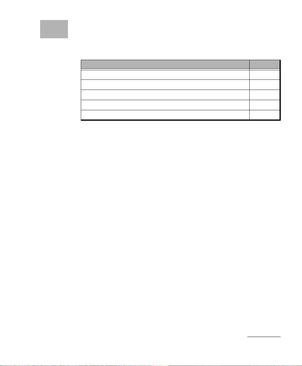
8 Test Applications
The BV10 supports the following test applications:
Test Application Page
Smart Loopback Test 74
Ping Test 76
TWAMP Light Responder Test 77
UDP Echo Responder Test 78
Ethernet OAM Handling Test 79
Smart Loopback supports wire-speed operation with TWAMP, UDP, and
OAM handlers.
In addition to the test applications listed above, the BV10 responds to ARP
and Ping packets targeted to the unit (not wire-speed).
The BV10 provides counters for the number of packets processed by each
test and each Ethernet OAM message type. Refer to show statistics on
page 49 for more information. The test application counters are
automatically reset when there is:
Link-up event on the Test port.
Any Test port configuration change.
Test control changes from disabled to enabled (applies to TWAMP
Light, UDP Echo, and Ethernet OAM handling).
The Smart Loopback Operational Status changes from Not Operational
to Operational (applies to Smart Loopback test).
The Smart Loopback mode is changed (applies to Smart Loopback
test).
All test application counters can be manually reset by entering the
statistics
Note: All tests at the exception of Ping are disabled during software upgrades on
the Test port.
BV10-100 and BV10-1000 73
command. Refer to clear statistics on page 50 for more information.
clear
Page 80

Test Applications
Smart Loopback Test
Smart Loopback Test
The Smart Loopback feature loops back the stream of data
(frames/packets). It retransmits incoming frames/packets after exchanging
the source and destination addresses as well as ports at multiple layers
(Ethernet MAC, IP, and UDP/TCP).
Smart Loopback can be enabled (default) or disabled. Refer to
smart-loopback enable|disable on page 70 for more information.
Modes
The Smart Loopback mode limits the address/port swapping to a specific
layer. The BV10 supports the following Smart Loopback modes:
UDP/TCP (default) – Swap MAC addresses, IP addresses, UDP or TCP
ports when present and addressed to the unit’s TEST port MAC/IP
address. In other words, swap from Layer 2 up to Layer 4 when
present.
IP – Swap MAC addresses, IP addresses when present and addressed
to the unit’s TEST port MAC/IP address. In other words, swap from
Layer 2 up to Layer 3 when present.
Ethernet – Swap MAC addresses when addressed to the unit’s TEST
port MAC address. In other words, swap Layer 2 when present.
Ethernet All Unicast – Swap MAC addresses when the address is
unicast, regardless of the unit’s MAC address.
Refer to smart-loopback mode ethernet-all-unicast|ethernet|ip|udp-tcp on
page 70 for more information.
74 BV10
Page 81

Test Applications
Smart Loopback Test
Operational Status
The following table indicates the rules that determine the Smart Loopback
operational status for each mode.
Smart Loopback
Mode
Ethernet All Unicast Not Operational Operational Operational
Ethernet Not Operational Operational Operational
IP Not Operational Operational Not Operational
UDP/TCP Not Operational Operational Not Operational
Note: Laser Off produces a Link Down status for the optical transceiver port.
Link Down
DHCP Acquired, DHCP
Renewing, or Manual IP address
Link Up
DHCP Acquiring
or DHCP Failed
BV10-100 and BV10-1000 75
Page 82

Test Applications
Ping Test
Ping Test
The Ping test (applicable to the LAN and Test ports) provides the ability to
generate ICMP Echo Requests and provides statistics on the ICMP Echo
Replies received in response to the ICMP Echo Request. ICMP Echo Replies
are expected on the same interface on which the ICMP Echo Requests
were sent.
The Ping test is always enabled, even during software upgrades on the Test
port.
The following table lists the Ping test parameters and default values where
applicable.
Destination IP address
Number of packets or continuous 4
Size in bytes 32
Parameter Default Value
Time-To-Live (TTL) 128
Delay (interval between packets) 1000 ms
Timeout 4000 ms
The Ping test returns the following statistics:
Number of packets transmitted.
Number of packets received.
Percentage of packet loss.
Round-trip time (rtt) in ms (minimum, average, maximum, and
standard deviation values).
Refer to ping on page 53 for more information.
76 BV10
Page 83

Test Applications
TWAMP Light Responder Test
TWAMP Light Responder Test
The TWAMP Light Responder test listens for TWAMP Light messages on the
specified UDP port and responds with a reflected packet when all of the
following criteria are met:
TWAMP Responder control is enabled (default).
Destination MAC address equals the MAC address of the Test port.
VLAN ID equals the VLAN ID of the Test port (if configured).
Destination IP address equals the IP address of the Test port.
Protocol equals UDP (17).
UDP destination port equals the configured TWAMP Listening UDP
port.
The TWAMP Light Responder test supports wire-speed operation.
Unauthenticated mode is assumed.
The TWAMP Light Responder test can be enabled (default) or disabled.
Refer to twamp enable|disable on page 71 for more information.
The UDP Listening port (default is 9495) is specified with the
twamp udp-port
command. Refer to twamp udp-port value on page 71 for more
information.
BV10-100 and BV10-1000 77
Page 84

Test Applications
UDP Echo Responder Test
UDP Echo Responder Test
The UDP Echo Responder test listens for UDP Echo messages and
responds with a reflected packet when all of the following criteria (as
defined in RFC962) are met:
UDP Responder control is enabled (default).
Destination MAC address equals the MAC address of the Test port.
VLAN ID equals the VLAN ID of the Test port (if configured).
Destination IP address equals the IP address of the Test port.
Protocol is UDP (17).
UDP destination port is 7 (UDP Echo, as per RFC862).
The UDP Echo Responder test supports wire-speed operation.
The UDP Echo Responder test can be enabled (default) or disabled. Refer
to udp-echo enable|disable on page 71 for more information.
78 BV10
Page 85

Test Applications
Ethernet OAM Handling Test
Ethernet OAM Handling Test
The Ethernet OAM handling test listens for Ethernet OAM messages in both
Ethernet II and 802.3 LLC/SNAP frame format and responds in the received
format.
No VLAN ID checking is done. The Ethernet OAM feature responds with
VLAN parameters of the received packet. In addition, no MEG-level
discrimination is done, which allows the BV10 to operate in promiscuous
mode (the unit operates as a MEP at multiple levels without any MEG-level
configuration).
Ethernet OAM handling can be globally enabled (default) or disabled. Refer
to eth-oam enable|disable on page 72 for more information.
The BV10 listens for and responds to the following Ethernet OAM
messages:
Loopback
The BV10 responds to Unicast OAM Loopback messages when all of
the following criteria are met:
Global Ethernet OAM handling is enabled (default).
Destination MAC address equals the MAC address of the Test port.
EtherType is 0x8902.
OpCode is 3 (LBM).
BV10-100 and BV10-1000 79
Page 86

Test Applications
Ethernet OAM Handling Test
Frame Delay (two-way)
The BV10 supports two-way Frame Delay. The BV10 responds to
Ethernet OAM Frame Delay messages when all of the following criteria
are met:
Global Ethernet OAM handling is enabled (default).
Destination MAC address equals the MAC address of the Test port.
EtherType is 0x8902.
OpCode is 47 (DMM).
Link Trace
The BV10 responds to Ethernet OAM Link Trace messages when all of
the following criteria are met:
Global Ethernet OAM handling is enabled (default).
Destination MAC address is 01-80-C2-00-00-3y, where y is a value
between [8-F] hexidecimal.
EtherType is 0x8902.
OpCode is 5 (LTM).
Target MAC address equals the MAC address of the Test port.
TTL is greater than 1.
LTM Egress Identifier TLV is present (Type equals 7).
80 BV10
Page 87

9 Power Failure Recovery
In the case of a power failure, the BV10 unit:
recovers automatically when power is restored.
returns to the same state as before the power failure.
maintains all configuration parameters such as Test port, Management
port, and Smart Loopback mode settings.
BV10-100 and BV10-1000 81
Page 88

Page 89

10 Maintenance
To help ensure long, trouble-free operation:
Always inspect fiber-optic connectors before using them and clean
them if necessary.
Keep the unit free of dust.
Clean the unit casing and front panel with a cloth slightly dampened
with water.
Store unit at room temperature in a clean and dry area. Keep the unit
out of direct sunlight.
Avoid high humidity or significant temperature fluctuations.
Avoid unnecessary shocks and vibrations.
If any liquids are spilled on or into the unit, turn off the power
immediately, disconnect from any external power source and let the
unit dry completely.
WARNING
The use of controls, adjustments and procedures, namely for
operation and maintenance, other than those specified herein may
result in hazardous radiation exposure or impair the protection
provided by this unit.
BV10-100 and BV10-1000 83
Page 90

Maintenance
Cleaning LC Connectors
Cleaning LC Connectors
Under normal circumstances the cleaning of the LC connector is not
required. However if the connector shows signs of debris or
contamination, cleaning may be required.
To clean a LC/SC/MPO-24 connector
1. Use a clean dry air (CDA) or a air gun to blow out the dust or
contamination.
2. Re-inspect the connector.
3. If the connector is still not clean, use a commercial cleaner
recommended by the SFP manufacturer.
Note: Refer to the transceiver manufacturer for more detailed cleaning
recommendations and instructions.
Recycling and Disposal (Applies to European Union Only)
For complete recycling/disposal information as per European Directive
WEEE 2012/19/UE, visit the EXFO Web site at www.exfo.com/recycle.
84 BV10
Page 91

11 Troubleshooting
Solving Common Problems
Before calling EXFO’s technical support, please read the following
common problems that can occur and their respective solution.
Problem Possible Cause Solution
Optical Laser LED is off and
the SFP is not generating the
signal.
CLI command returns:
Operation failed,
address/netmask not
permitted. Same subnet as
other interface.
There is a configuration
mismatch between the
inserted SFP and the rate
selected for the test.
The SFP is not compatible
with the BV10-1000.
LAN and TEST ports IP
addresses are under same
subnet or within its range.
Ensure that the SFP is
supporting the rate used for
the test.
Ensure to use a compatible
SFP.
Make sure to define IP
addresses under different
subnet range.
BV10-100 and BV10-1000 85
Page 92

Troubleshooting
Contacting the Technical Support Group
Contacting the Technical Support Group
To obtain after-sales service or technical support for this product, contact
EXFO at one of the following numbers. The Technical Support Group is
available to take your calls from Monday to Friday, 8:00 a.m. to 7:00 p.m.
(Eastern Time in North America).
Technical Support Group
400 Godin Avenue
Quebec (Quebec) G1M 2K2
CANADA
For detailed information about technical support, and for a list of other
worldwide locations, visit the EXFO Web site at www.exfo.com.
If you have comments or suggestions about this user documentation, you
can send them to customer.feedback.manual@exfo.com.
To accelerate the process, please have information such as the name and
the serial number (see the product identification label), as well as a
description of your problem, close at hand.
1 866 683-0155 (USA and Canada)
Tel.: 1 418 683-5498
Fax: 1 418 683-9224
support@exfo.com
Transportation
Maintain a temperature range within specifications when transporting the
unit. Transportation damage can occur from improper handling. The
following steps are recommended to minimize the possibility of damage:
Pack the unit in its original packing material when shipping.
Avoid high humidity or large temperature fluctuations.
Keep the unit out of direct sunlight.
Avoid unnecessary shocks and vibrations.
86 BV10
Page 93

12 Warranty
General Information
EXFO Inc. (EXFO) warrants this equipment against defects in material and
workmanship for a period of 1 year from the date of original shipment.
EXFO also warrants that this equipment will meet applicable specifications
under normal use.
During the warranty period, EXFO will, at its discretion, repair, replace,
or issue credit for any defective product, as well as verify and adjust the
product free of charge should the equipment need to be repaired or if the
original calibration is erroneous. If the equipment is sent back for
verification of calibration during the warranty period and found to meet all
published specifications, EXFO will charge standard calibration fees.
The warranty can become null and void if:
unit has been tampered with, repaired, or worked upon by
unauthorized individuals or non-EXFO personnel.
warranty sticker has been removed.
IMPORTANT
case screws, other than those specified in this guide, have been
removed.
case has been opened, other than as explained in this guide.
unit serial number has been altered, erased, or removed.
unit has been misused, neglected, or damaged by accident.
THIS WARRANTY IS IN LIEU OF ALL OTHER WARRANTIES EXPRESSED,
IMPLIED, OR STATUTORY, INCLUDING, BUT NOT LIMITED TO, THE
IMPLIED WARRANTIES OF MERCHANTABILITY AND FITNESS FOR A
PARTICULAR PURPOSE. IN NO EVENT SHALL EXFO BE LIABLE FOR
SPECIAL, INCIDENTAL, OR CONSEQUENTIAL DAMAGES.
BV10-100 and BV10-1000 87
Page 94

Warranty
Liability
Liability
EXFO shall not be liable for damages resulting from the use of the product,
nor shall be responsible for any failure in the performance of other items to
which the product is connected or the operation of any system of which
the product may be a part.
EXFO shall not be liable for damages resulting from improper usage or
unauthorized modification of the product, its accompanying accessories
and software.
88 BV10
Page 95

Warranty
Exclusions
EXFO reserves the right to make changes in the design or construction of
any of its products at any time without incurring obligation to make any
changes whatsoever on units purchased. Accessories, including but not
limited to fuses, pilot lamps, batteries and universal interfaces (EUI) used
with EXFO products are not covered by this warranty.
This warranty excludes failure resulting from: improper use or installation,
normal wear and tear, accident, abuse, neglect, fire, water, lightning or
other acts of nature, causes external to the product or other factors beyond
the control of EXFO.
IMPORTANT
In the case of products equipped with optical connectors, EXFO will
charge a fee for replacing connectors that were damaged due to
misuse or bad cleaning.
Certification
Exclusions
EXFO certifies that this equipment met its published specifications at the
time of shipment from the factory.
BV10-100 and BV10-1000 89
Page 96

Warranty
Service and Repairs
Service and Repairs
EXFO commits to providing product service and repair for five years
following the date of purchase.
To send any equipment for service or repair:
1. Call one of EXFO’s authorized service centers (see EXFO Service
2. If equipment must be returned to EXFO or an authorized service
3. If possible, back up your data before sending the unit for repair.
4. Pack the equipment in its original shipping material. Be sure to include
5. Return the equipment, prepaid, to the address given to you by support
Centers Worldwide on page 91). Support personnel will determine if
the equipment requires service, repair, or calibration.
center, support personnel will issue a Return Merchandise
Authorization (RMA) number and provide an address for return.
a statement or report fully detailing the defect and the conditions under
which it was observed.
personnel. Be sure to write the RMA number on the shipping slip. EXFO
will refuse and return any package that does not bear an RMA number.
Note: A test setup fee will apply to any returned unit that, after test, is found to
meet the applicable specifications.
After repair, the equipment will be returned with a repair report. If the
equipment is not under warranty, you will be invoiced for the cost
appearing on this report. EXFO will pay return-to-customer shipping costs
for equipment under warranty. Shipping insurance is at your expense.
Routine recalibration is not included in any of the warranty plans. Since
calibrations/verifications are not covered by the basic or extended
warranties, you may elect to purchase FlexCare Calibration/Verification
Packages for a definite period of time. Contact an authorized service center
(see EXFO Service Centers Worldwide on page 91).
90 BV10
Page 97

Warranty
EXFO Service Centers Worldwide
EXFO Service Centers Worldwide
If your product requires servicing, contact your nearest authorized service
center.
EXFO Headquarters Service Center
400 Godin Avenue
Quebec (Quebec) G1M 2K2
CANADA
EXFO Europe Service Center
Winchester House, School Lane
Chandlers Ford, Hampshire S053 4DG
ENGLAND
EXFO Telecom Equipment
(Shenzhen) Ltd.
3rd Floor, Building 10,
Yu Sheng Industrial Park (Gu Shu
Crossing), No. 467,
National Highway 107,
Xixiang, Bao An District,
Shenzhen, China, 518126
1 866 683-0155 (USA and Canada)
Tel.: 1 418 683-5498
Fax: 1 418 683-9224
support@exfo.com
Tel.: +44 2380 246800
Fax: +44 2380 246801
support.europe@exfo.com
Tel: +86 (755) 2955 3100
Fax: +86 (755) 2955 3101
support.asia@exfo.com
To view EXFO's network of partner-operated Certified Service Centers
nearest you, please consult EXFO's corporate website for the complete list
of service partners:
http://www.exfo.com/support/services/instrument-services/
exfo-service-centers.
BV10-100 and BV10-1000 91
Page 98

Page 99

ASpecifications
General Specifications
BV10
Size (H x W x D) 38 mm x 103 mm x 210 mm (1 1/2 in x 4 1/16 in x 8 1/4 in)
Weight (without transceiver) 0.6 kg (1.3 lb)
Te mp e r at u r e
Operating:
Storing:
Relative humidity 5% to 95%, non-condensing
Maximum operation altitude 4000 m (13123 ft)
Pollution degree 2 (for indoor use only)
Measurement category Not rated for measurement categories II, III, or IV.
Overvoltage category I
AC version input power 9 V; 1 A
DC –48 V input power –40 - –72 V; 0.2 A
DC +24 V input power 20 - 32 V; 0.4 A
0 °C to 50 °C (32 °F to 122 °F)
-40 °C to 70 °C (-40 °F to 158 °F)
BV10-100 and BV10-1000 93
Page 100

Specifications
General Specifications
AC/DC Adapter
Te mp e r at u r e
Relative humidity 5% to 95%, non-condensing
Maximum operation altitude 2000 m (6562 ft)
Pollution degree 2 (for indoor use only)
Measurement category Not rated for measurement categories II, III, or IV.
Overvoltage category II
Power Supply Rating
a. AC/DC adapter must be a Listed/Certified (external direct plug-in SMPSU, Overvoltage
(Installation) category II) having reinforced insulation between primary and secondary
and suitably rated for the extended BV10 operating environmental conditions (altitude,
temperature, and humidity) and with output rating (voltage and current) compatible
with above specifications.
b. Use the external power supply indoors only.
c. No exceeding ± 10% of the nominal voltage.
Operating:
Storing:
bc
Input:
Output:
–10 °C to 50 °C (14 °F to 122 °F)
–20 °C to 85 °C (–4 °F to 185 °F)
a
100 - 240 V; 50/60 Hz; 0.7 A Max.
Output: 9 V; 1.66 A
94 BV10
 Loading...