

Page 1
AXS-200/850
Ethernet Test Set
User Guide
Page 2

Copyright © 2007–2009 EXFO Electro-Optical Engineering Inc. All rights
reserved. No part of this publication may be reproduced, stored in a
retrieval system or transmitted in any form, be it electronically,
mechanically, or by any other means such as photocopying, recording or
otherwise, without the prior written permission of EXFO Electro-Optical
Engineering Inc. (EXFO).
Information provided by EXFO is believed to be accurate and reliable.
However, no responsibility is assumed by EXFO for its use nor for any
infringements of patents or other rights of third parties that may result from
its use. No license is granted by implication or otherwise under any patent
rights of EXFO.
EXFO’s Commerce And Government Entities (CAGE) code under the North
Atlantic Treaty Organization (NATO) is 0L8C3.
The information contained in this publication is subject to change without
notice.
Trademarks
EXFO’s trademarks have been identified as such. However, the presence
or absence of such identification does not affect the legal status of any
trademark.
Units of Measurement
Units of measurement in this publication conform to SI standards and
practices.
December 17, 2009
Version number: 6.0.0
ii AXS-200/850
Page 3

Contents
Contents
Certification Information ......................................................................................................vii
1 Introducing the AXS-200/850 Ethernet Test Set ......................................... 1
Features and Benefits ..............................................................................................................1
Models ....................................................................................................................................2
Software Options ....................................................................................................................3
Optical Transceivers (SFP) ........................................................................................................4
Conventions ............................................................................................................................5
2 Safety Information ....................................................................................... 7
Laser Safety Warnings .............................................................................................................7
Installation Instructions Warnings ..........................................................................................8
3 Getting Started ............................................................................................ 9
Power Sources ........................................................................................................................9
Turning the Unit On ................................................................................................................9
4 Using the Smart User Interface ................................................................. 11
Keypad ..................................................................................................................................11
Home Menu ..........................................................................................................................12
Page Elements ......................................................................................................................19
5 Signal Connection and LEDs ...................................................................... 21
Electrical 10/100/1000 Mbps Ethernet Port ...........................................................................22
Optical 100/1000 Mbps Ethernet Port ..................................................................................23
AXS-200/850 Ethernet Test Set LEDs .....................................................................................25
6 Configuring and Starting a Test or Tool ................................................... 27
Configuring an RFC 2544 Test ...............................................................................................27
Configuring a BERT Test ........................................................................................................28
Configuring a Traffic Generation & Monitoring Test ..............................................................29
Configuring a Smart Loopback Test ......................................................................................31
Configuring a Ping Tool ........................................................................................................31
Configuring a Trace Route Tool .............................................................................................32
Configuring Cable Test Tool ..................................................................................................32
Ethernet Test Set iii
Page 4

Contents
7 Setup ...........................................................................................................33
Interface ...............................................................................................................................33
Port .......................................................................................................................................34
Network ................................................................................................................................37
Default Gateway ...................................................................................................................42
VLAN ....................................................................................................................................43
SFP ........................................................................................................................................44
Remote Selection ..................................................................................................................45
Module .................................................................................................................................51
Save & Load Config ..............................................................................................................52
8 RFC 2544 ......................................................................................................57
Global Configuration ............................................................................................................58
Stream Configuration ...........................................................................................................62
Throughput Configuration ....................................................................................................66
Back-to-Back Configuration ..................................................................................................69
Frame Loss Configuration .....................................................................................................71
Latency Configuration ..........................................................................................................73
Summary Results ..................................................................................................................75
Throughput Results ..............................................................................................................82
Back-to-Back Results .............................................................................................................84
Frame Loss Results ................................................................................................................86
Latency Results .....................................................................................................................88
Graph ...................................................................................................................................90
Alarms/Errors ........................................................................................................................91
9 BERT .............................................................................................................97
Global Configuration ............................................................................................................99
Stream Configuration .........................................................................................................103
Summary Results ................................................................................................................107
Detailed Results ..................................................................................................................113
Service Disruption Results ...................................................................................................114
Alarms/Errors ......................................................................................................................116
Logger ................................................................................................................................119
iv AXS-200/850
Page 5

Contents
10 Traffic Generation & Monitoring ............................................................. 125
Global Configuration ..........................................................................................................127
Shaping Configuration .......................................................................................................130
Stream Configuration .........................................................................................................132
Sequence Configuration .....................................................................................................136
Jitter/Latency Configuration ................................................................................................138
Transmit Configuration .......................................................................................................142
Stream Configuration .........................................................................................................144
Network Configuration .......................................................................................................149
Default Gateway ........................................................................................................... 153
VLAN Configuration ............................................................................................................155
Summary Results ................................................................................................................156
Throughput Results ............................................................................................................165
Sequence Results ................................................................................................................167
Jitter/Latency Results ...........................................................................................................171
Alarms/Errors Results ..........................................................................................................173
Frame Count Results ...........................................................................................................176
Frame Size Results ..............................................................................................................177
Flow Control Results ...........................................................................................................179
Logger ................................................................................................................................180
11 Smart Loopback ....................................................................................... 185
Statistics .............................................................................................................................185
12 Tools .......................................................................................................... 187
Ping Configuration .............................................................................................................188
Ping Results ........................................................................................................................190
Ping Statistics .....................................................................................................................193
Trace Route Configuration ..................................................................................................194
Trace Route Results .............................................................................................................195
Cable Test Configuration .....................................................................................................198
Cable Test Results - Summary ..............................................................................................201
Cable Test Results - Wire Map .............................................................................................203
Cable Test Results - Delay/Length ........................................................................................207
Report Configuration ..........................................................................................................209
Report File ..........................................................................................................................211
13 System ...................................................................................................... 213
File Manager .......................................................................................................................214
VNC ....................................................................................................................................216
Module Information ...........................................................................................................220
Ethernet Test Set v
Page 6

Contents
14 Maintenance ..............................................................................................221
Calibration Statement .........................................................................................................222
Recycling and Disposal (Applies to European Union Only) ..................................................223
15 Troubleshooting ........................................................................................225
Solving Common Problems .................................................................................................225
Contacting the Technical Support Group ............................................................................226
Transportation ....................................................................................................................227
16 Warranty ....................................................................................................229
General Information ...........................................................................................................229
Liability ...............................................................................................................................230
Exclusions ...........................................................................................................................230
Certification ........................................................................................................................230
Service and Repairs .............................................................................................................231
EXFO Service Centers Worldwide ........................................................................................232
A Specifications ............................................................................................233
B Glossary .....................................................................................................237
Acronym List .......................................................................................................................237
VLAN ..................................................................................................................................244
Index ...............................................................................................................245
vi AXS-200/850
Page 7

Certification Information
Certification Information
Federal Communications Commission (FCC) and
Industry Canada (IC) Information
Electronic test and measurement equipment is exempt from FCC Part 15
compliance in the United States and from IC ICES 003 compliance in
Canada. However, EXFO Electro-Optical Engineering Inc. (EXFO) makes
reasonable efforts to ensure compliance to the applicable standards.
The limits set by these standards are designed to provide reasonable
protection against harmful interference when the equipment is operated in
a commercial environment. This equipment generates, uses, and can
radiate radio frequency energy and, if not installed and used in accordance
with the user guide, may cause harmful interference to radio
communications. Operation of this equipment in a residential area is likely
to cause harmful interference in which case the user will be required to
correct the interference at his own expense.
European Union (CE) Information
Electronic test and measurement equipment is subject to the EMC
Directive in the European Union. The EN61326 standard prescribes both
emission and immunity requirements for laboratory, measurement, and
control equipment. This unit has been tested and found to comply with the
limits for a Class A digital device. Please refer to the CE Declaration of
Conformity on page ix.
Note: If the equipment described herein bears the CE symbol, the said equipment
complies with the applicable European Union Directive and Standards
mentioned in the Declaration of Conformity.
Ethernet Test Set vii
Page 8

Certification Information
Laser
Class 1 laser product.
This product complies with 21 CFR 1040.10 except for deviations pursuant
to Laser Notice No. 50, dated July 26, 2001 and with IEC 60825-1:2001 and
EN 60825-1:1994 +A11:1996 +A2:2001 +A1:2002.
viii AXS-200/850
Page 9
CE Declaration of Conformity
CONFO
Certification Information
DECLARATIONOF
Application of Council Directive(s): 2006/95/EC - The Low Voltage Directive
Manufacturer’s Name: EXFO Electro-Optical Engineering Inc.
Manufacturer’s Address: 400 Godin Avenue
Equipment Type/Environment: Test & Measurement / Industrial
Trade Name/Model No.: AXS-200/850
Standard(s) to which Conformity is Declared:
EN 61010-1:2001 Safety Requirements for Electrical Equipment for Measurement,
EN 61326-1:2006 Electrical Equipment for Measurement, Control and Laboratory Use
EN 60825-1:1994
+A11:1996 +A2:2001 +A1:2002
I, the undersigned, hereby declare that the equipment specified above conforms to the above Directive and Standards.
Manufacturer
Control, and Laboratory Use, Part 1: General Requirements.
– EMC Requirements – Part 1: General Requirements.
Safety of Laser Products – Part 1: Equipment classification,
requirements and user’s guide.
2004/108/EC - The EMC Directive
and their amendments
Quebec, Quebec
Canada, G1M 2K2
Ethernet Test Set
RMITY
Signature:
Full Name: Stephen Bull, E. Eng
Position: Vice-President Research and
Address: 400 Godin Avenue, Quebec (Quebec),
Date: February 1, 2009
Development
Canada, G1M 2K2
Ethernet Test Set ix
Page 10

Page 11

1 Introducing the AXS-200/850
Ethernet Test Set
The AXS-200/850 Ethernet Test Set provides Ethernet testing capability on the
AXS-200. It supports one electrical interface through an RJ-45 connector and
one optical interface through a standard pluggable SFP. The AXS-200/850
Ethernet Test Set provides a comprehensive offering of test features such as
RFC 2544, BERT over IP, Traffic Generation & Monitoring, Smart Loopback,
Ping, Trace Route, Remote loopback, and Cable Test.
Features and Benefits
³ All-in-one unit for installing, turning up and maintaining Metro Ethernet
Circuits over IPv4/IPv6
³ User-definable RFC-2544 test routines
³ Asymmetrical network testing capability fully controlled from the local
module (DTS RFC 2544)
³ Bit-error-rate testing (BERT) up to layer 4
³ Traffic Generation & Monitoring test used for performance evaluation
of Ethernet or IP network
³ Ethernet cable testing: Category 3/Class C, Category 4, Category 5,
Category 5e/Class D, and Category 6e/Class E
³ Intelligent network auto discovery for simplified loopback testing and
asymmetrical network testing
³ Configurable VLAN with Q-in-Q capability
³ QoS, ToS, and Diffserv capabilities
³ Pass/Fail results (LED indicators) with user defined thresholds
³ Event logger for the Traffic Generation & Monitoring and BERT tests. It
provides an historical account of the events recorded while a test case
was running, including the threshold crossing events.
Ethernet Test Set 1
Page 12
Introducing the AXS-200/850 Ethernet Test Set
Models
³ One electrical interface supporting:
10 Mbps
100 Mbps
1000 Mbps
³ One optical interface supporting:
100 Mbps
1000 Mbps
³ Service Disruption Time (SDT) measurement
Models
Two models are available and are described as follows:
Model Description
AXS-850 Ethernet 10Base-T/100Base-TX electrical.
AXS-850-1 Ethernet 10/100/1000 electrical and GigE optical.
2 AXS-200/850
Page 13

Introducing the AXS-200/850 Ethernet Test Set
Software Options
Software Options
Software keys are available to enable additional services. For information
on how to install and activate software options, refer to the AXS-200 User
Guide.
Options Description
100optical Enable support for 100 Mbps optical interface.
The displayed name on the Software Options tab is
100M-O-AP.
GigE Enable support for 1000Base-T and GigE optical interface.
The displayed name on the Software Options tab is
1000M-E and 1000M-O.
Cable_Test Enable support for Ethernet electrical cable test.
The displayed name on the Software Option tab is
Cable_Test.
Traffic_Gen Enable Traffic Generation & Monitoring test. The displayed
name on the Software Option tab is Traffic_Gen.
Multiple_
Streams
IPV6 Enable support for IPV6 testing. The IP version can only be
Ethernet Test Set 3
Enable support for Background Streams Configuration and
Monitoring of the Traffic Generation & Monitoring test. The
Background Streams option can only be activated once the
Traffic_Gen software option is activated. The displayed
name on the Software Option tab is Multiple_ Streams.
configurable once the IPV6 software option is activated.
The displayed name on the Software Option tab is IPV6.
Page 14
Introducing the AXS-200/850 Ethernet Test Set
Optical Transceivers (SFP)
Optical Transceivers (SFP)
The following table lists the compatible SFPs that can be ordered through
EXFO.
EXFO Part
Number
FTB-85911 100Base-LX10, 1310 nm, 15 Km
FTB-85910 100Base-FX, 1310 nm, 2 Km
FTB-8592 1000Base-ZX, 1550 nm, 80 Km
FTB-8591 1000Base-LX, 1310 nm, 10 Km
FTB-8590 1000Base-SX, 850 nm, 550 m
FTB-8597 1000Base-BX10-U, Bi-directional 1310 nm TX, 1490 nm RX,
10 Km
FTB-8596 1000Base-BX10-D, Bi-directional 1490 nm TX, 1310 nm RX,
10 Km
Description
4 AXS-200/850
Page 15
Introducing the AXS-200/850 Ethernet Test Set
Conventions
Conventions
Before using the product described in this manual, you should understand
the following conventions:
WARNING
Indicates a potentially hazardous situation which, if not avoided,
could result in death or serious injury. Do not proceed unless you
understand and meet the required conditions.
CAUTION
Indicates a potentially hazardous situation which, if not avoided,
may result in minor or moderate injury. Do not proceed unless you
understand and meet the required conditions.
CAUTION
Indicates a potentially hazardous situation which, if not avoided,
may result in component damage. Do not proceed unless you
understand and meet the required conditions.
IMPORTANT
Refers to information about this product you should not overlook.
Ethernet Test Set 5
Page 16

Page 17
2 Safety Information
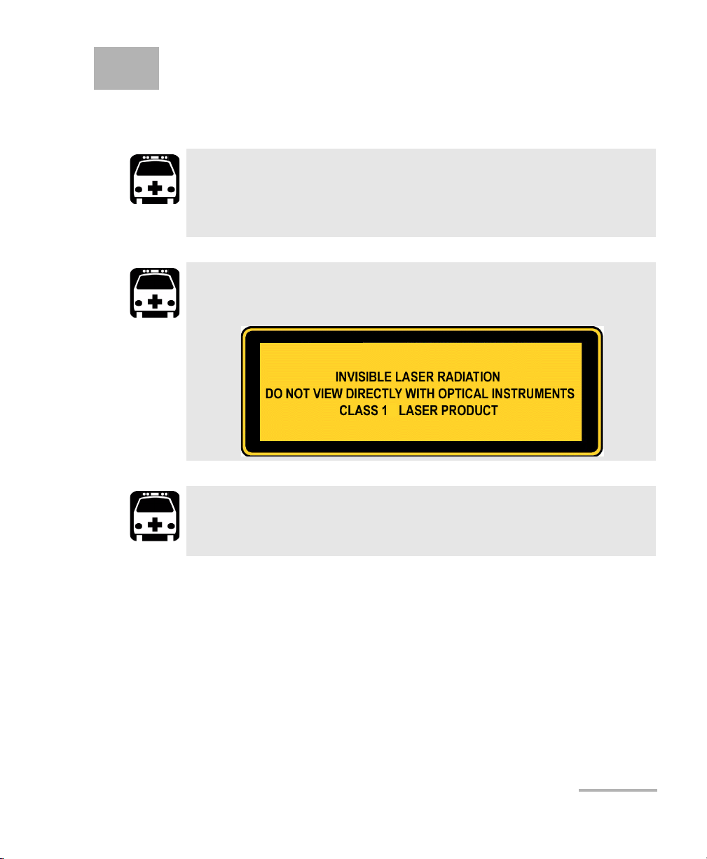
Laser Safety Warnings
WARNING
Do not install or terminate fibers while a laser source is active.
Never look directly into a live fiber, and ensure that your eyes are
protected at all times.
WARNING
This product may employ a Class 1 SFP.
WARNING
When the LASER LED is on, the AXS-200/850 is receiving/emitting an
optical signal.
Ethernet Test Set 7
Page 18

Safety Information
Installation Instructions Warnings
Installation Instructions Warnings
No user serviceable parts are contained inside. Contact the
manufacturer regarding service of this equipment.
All wiring and installation must be in accordance with local building
and electrical codes acceptable to the authorities in the countries
where the equipment is installed and used.
Electrostatic Discharge (ESD) Sensitive Equipment:
To minimize the risk of damage, dissipate static electricity by
touching a grounded unpainted metal object
CAUTION
IMPORTANT
CAUTION
³ before connecting or disconnecting cables to/from the module.
³ before inserting or removing SFPs to/from the module.
8 AXS-200/850
Page 19

3 Getting Started
Windows CE 6.0 is the baseline operating system software and is
pre-installed on the Sharp Tester. If the AXS-200/850 Ethernet Test Set is not
already installed, refer to the Sharp Tester User Guide for more information
on how to install the module.
Power Sources
The unit operates with the following power sources:
³ AC adapter/charger (connected to standard power outlet—indoor use
only). Compatible car outlet adapter available upon request.
³ One Lithium-Ion rechargeable batteries (automatically take over if you
disconnect the AC adapter/charger). Battery recharge is automatic
when the AC adapter/charger is connected.
Turning the Unit On
Turn on the AXS-200 by pressing the button. Refer to the AXS-200 User
Guide for more information.
Ethernet Test Set 9
Page 20

Page 21
4 Using the Smart User Interface
Keypad
Refer to the AXS-200 User Guide for more information on how to use the
keypad. The naming convention and purpose for each key is described in
the AXS-200 User Guide.
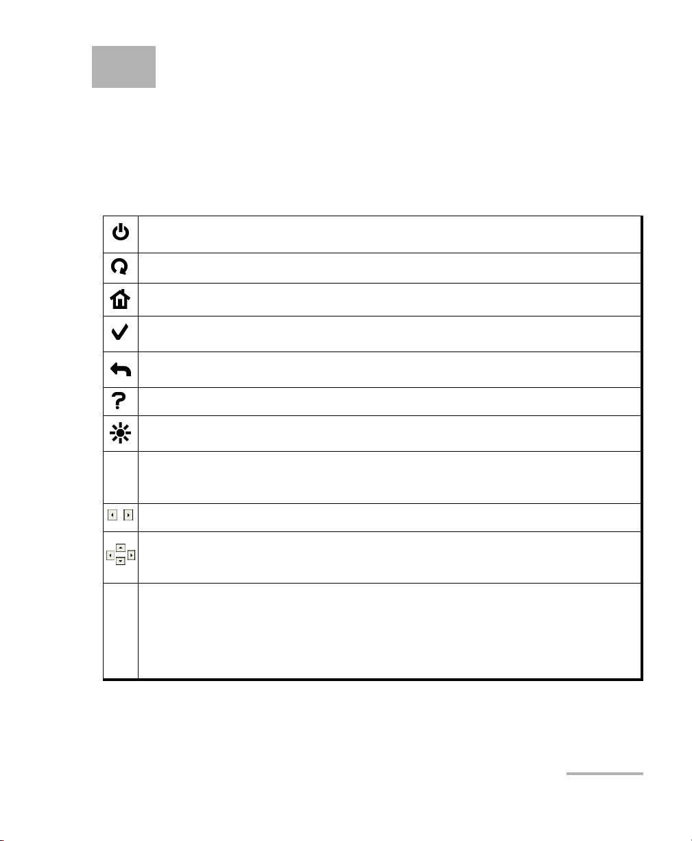
Power: Turns the unit on and off or puts it into suspend/resume mode.
Start/Stop: Starts and stops the test/tool.
Home: Brings the screen back to the Home menu.
Select: Selects the highlighted item on the screen. Also used to edit and to close a
field.
Back: Returns to the previous screen or menu. In edition mode, it cancels the
data-entry.
Help: Opens and closes the help for the current window.
Brightness: Controls lighting level of screen.
Function Keys: Located under the screen, the three function keys F1, F2, F3 are
F
used to select the tabs on the screen positioned directly above each key (for
example, F1 is used to select the left-most tab).
Function Arrows: Displays the previous or next set of tabs.
Navigation Arrows: Used to navigate and highlight items within a window. The
up and down arrow keys can be used in edition mode to increase or decrease the
number value.
Alpha-numeric Keypad: Used to perform the following:
³ Enter numbers and letters onto the screen in the same manner as a phone
keypad (for example, for the letter “B”, press the number “2” button two
times).
³ Select menu items by pressing the corresponding numbers.
Ethernet Test Set 11
Page 22
Using the Smart User Interface
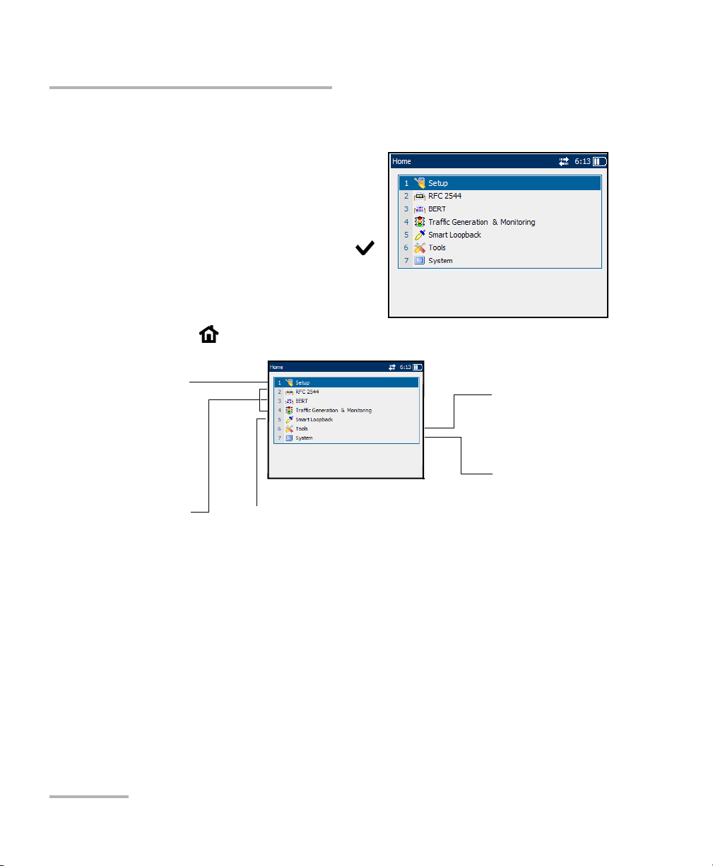
Home Menu
Home Menu
Upon start up, the Home menu is
displayed. Use the up and down
navigation arrows to navigate and
highlight menu items.
Note: To choose a menu item, press the
button or press the keypad number
corresponding to the number of the
item.
Press the button to return to the Home menu from any screen.
Setup: Allows to configure
the test interface, module,
remote selection, and
save/load the complete unit
configuring the subtests and
BERT: Allows Ethernet traffic
generation and analysis up
to Layer 4 with specific test
pattern for Bit Error Rate
Monitoring: Allows traffic
generation and analysis to
qualify the performance of
configuration.
RFC 2544: Allows
viewing test results.
analysis.
Traffic Generation &
Ethernet or IP Network.
Smart Loopback: Allows transmitting back the
stream of data while interchanging the source
and destination addresses of the MAC, IP and
UDP/TCP layers.
Tools: Allows to ping,
trace route, cable test,
and report.
System: Allows file
management, system
settings, software
options management,
and display of system
information.
12 AXS-200/850
Page 23

Using the Smart User Interface
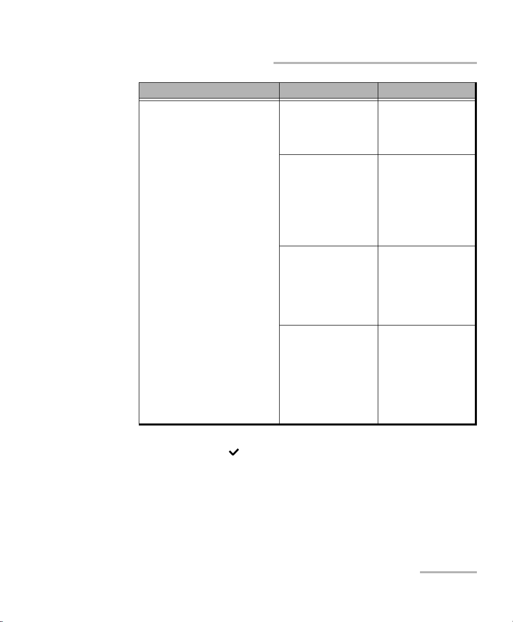
The Home menu offers the following content:
Home Menu Submenu Tab s /Pa ges
1. Setupa: Allows to configure
the test interface, module,
remote selection, and
save/load the complete unit
configuration.
1. Interface
Displays tabs used
to set up the
interface before
starting a test case.
a
Home Menu
b
:
Port
Network
Default Gateway
c
VLAN
SFP
2. Remote: Displays
tabs used to
configure manual
selection and
discovery.
3. Module: Displays
the page to
configure the
module settings.
4. Save & Load
Config: Displays the
page to save the test
settings and load
them whenever
required.
Manual Selection
Discovery
Ethernet Test Set 13
Page 24

Using the Smart User Interface
Home Menu
Home Menu Submenu Tab s /Pa ges
2. RFC 2544: Allows to
configure the subtests and to
view test results.
3. BERT: Allows Ethernet
traffic generation and analysis
up to Layer 4 with specific
test pattern for Bit Error Rate
analysis.
1. Configuration:
Displays tabs to
configure the global
and stream settings
and the subtest
settings.
2. Results: Displays
tabs to view results
and alarms/errors.
1. Configuration:
Displays tabs to
configure the global
and stream settings.
2. Results: Displays
tabs to view results
and alarms/errors.
Global
Stream
Throughput
Back-to-Back
Frame Loss
Latency
Summary
Throughput
Back-to-Back
Frame Loss
Latency
Graph
Alarms/Errors
Global
Stream
Summary
Detailed
Service Disruption
Alarms/Errors
3. Logger: Displays
the list of recorded
events.
14 AXS-200/850
Page 25

Using the Smart User Interface
Home Menu
Home Menu Submenu Tab s /Pa ges
4. Traffic Generation &
Monitoring: Traffic
Generation & Monitoring test
is used for performance
evaluation of Ethernet or IP
network.
1. Stream Config:
Displays tabs to
configure the main
stream and global
test properties
settings.
2. Background
Streams Config:
Displays tabs to
configure the
Background stream
properties.
3. Results: Displays
tabs to view results.
Global
Shaping
Stream
Sequence
Jitter/Latency
Transmit
Stream
Network
Default Gateway
VLAN
Summary
Throughput
Sequence
Jitter/Latency
Alarms/Errors
Frame Counts
Frame Size
Flow Control
c
4. Logger: Displays
the list of recorded
events.
5. Smart Loopback: Allows
transmitting back the stream
of data while interchanging
the source and destination
addresses of the MAC, IP and
UDP/TCP layers.
Ethernet Test Set 15
Page 26

Using the Smart User Interface
Home Menu
Home Menu Submenu Tab s /Pa ges
6. Tools: Allows to ping, trace
route,cable test, and report.
1. Ping: Displays
tabs to configure
ping and to view
results and statistics.
2. Trace Route:
Displays tabs to
configure trace
route and view
results.
3. Cable Test:
Displays tabs to
configure cable test
and view results.
4. Report: Allows to
configure and save
reports.
Configuration
Results
Statistics
Configuration
Results
Configuration
Results
Configuration
File
b
16 AXS-200/850
Page 27
Using the Smart User Interface
Home Menu
Home Menu Submenu Tab s /Pa ges
7. Systemd: Allows file
management, system
settings, software options
management, and display of
system information.
1. Utilities: Displays
the File Manager
utility and VNC
support.
2. Settings: Displays
submenus to
configure system
settings.
3. Software
Options: Displays
tabs to select and
activate software
option for module
and platform.
4. Information:
Displays tabs to view
company, system
and module
information.
1. File Manager
2. VNC
1. Date and Time
2. Display and
Language
3. Network
Connection
4. Power
Module
Platform
About
Module
Application
Platform
Memory
Components
a. The items in the Home menu and Submenu columns are numbered and can be
selected with the button or by pressing on the corresponding number on the
keypad.
b. The items that are numbered in the Ta bs / Pa g e column are pages and can be selected
by pressing on the corresponding numbers. Items in this column that are not
numbered are tabs and can be selected using the corresponding function keys
(F1/F2/F3) under the screen.
c. The Default Gateway tab is only available when the selected IP version is IPv6.
d. Information on the System menu item is covered in the AXS-200 User Guide.
Ethernet Test Set 17
Page 28
Using the Smart User Interface
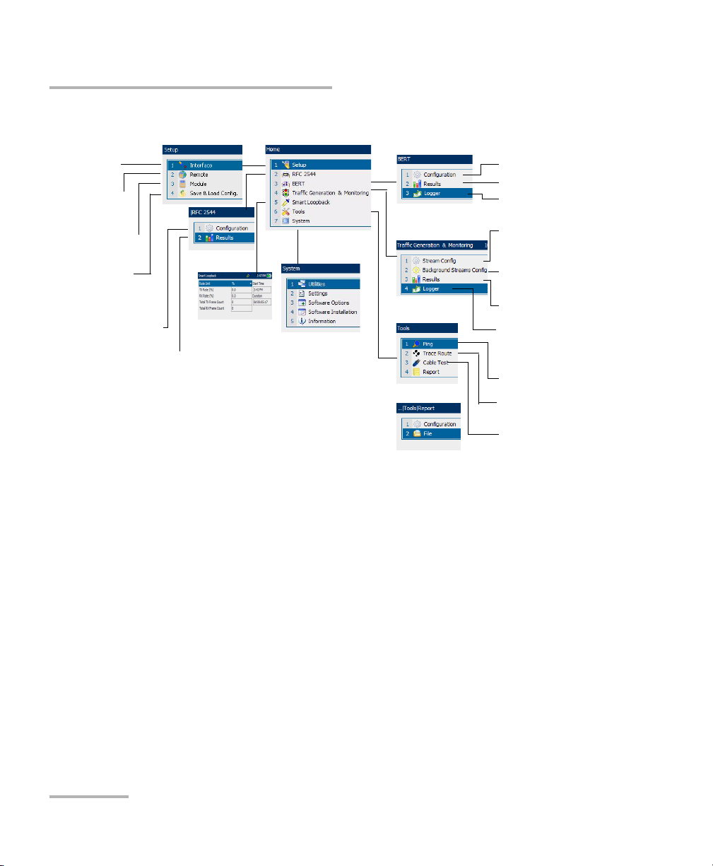
Home Menu
The menu structure is shown as follows.
Interface
Setup
Remote Manual
Selection and
Discovery
Module Information
Save & Load
Config.
RFC 2544 test
configuration
RFC 2544 test results
BERT configuration
BERT results
BERT Logger
Traffic Generation &
Monitoring Stream
configuration
Traffic Generation &
Monitoring Background
Stream configuration
Traffic Generation &
Monitoring results
Smart
Loopback
See AXS-200
User Guide for
System Menu
information
Traffic Generation &
Monitoring Logger
Ping configuration and
results
Trace Route configuration
and results
Cable Test configuration
and results
Tabs
If more than one page exists on the same screen, the names of these pages
are displayed as tabs on the bottom of the screen. To access a page, press
the function (F1/F2/F3) keys beneath the tab name. If an arrow appears
next to the tabs on the bottom of the screen (see the following figure), use
the function arrow keys to scroll to the next set of tabs.
18 AXS-200/850
Page 29
Using the Smart User Interface
Page Elements
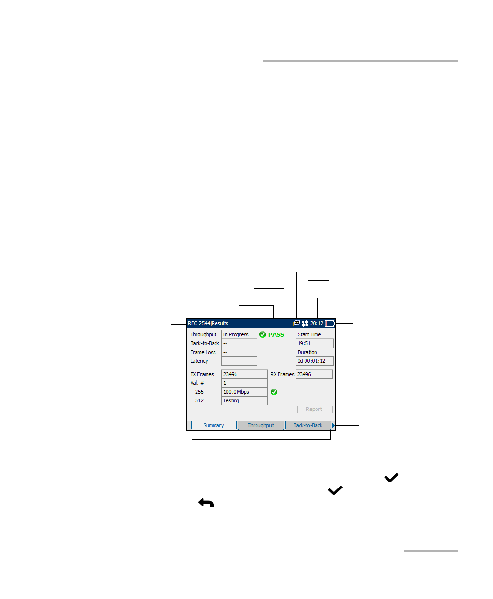
Page Elements
The title bar (blue bar) on the top of the screen is common to every page. It
displays the following from left to right:
³ The path and name of the page
³ The optical power
³ Remote Loopback icon
³ Test/ t ool ico n
³ Active Sync indicator
³ Time (optional)
³ Power source indicator
Test/Tool icon
Remote Loopback icon
Optical power
Page Name
Ta bs
Active Sync indicator
Time (optional)
Power source
indicator
Arrow to indicate
more tabs on the
next screen.
Use the arrow buttons to navigate the fields and press the button to
select the parameter for each field. Press the button to open a field for
editing and the button to exit the edit mode.
Ethernet Test Set 19
Page 30

Using the Smart User Interface
Page Elements
Help
The help button (?) displays the help information on the current page. It is
possible to navigate through the help information with the navigation
arrows once the help window is opened. The help button (?) also closes
the help window.
20 AXS-200/850
Page 31

5 Signal Connection and LEDs
This section describes all connectors (ports) and LEDs available on the
AXS-200/850 Ethernet Test Set.
10/100/1000 Mbps
Electrical with
RJ-45 connector
100/1000 Mbps Optical SFP
with Dual or Simplex
LC connector
The AXS-200/850 Ethernet Test Set is equipped with one RJ-45 electrical
and one SFP optical port (location of Laser/LED aperture).
Note: An SFP can be replaced at any time. If an SFP is changed while the optical
interface is selected and active, the laser will turn on automatically. Use
caution when installing the SFP in case the laser is enabled.
Ethernet Test Set 21
Page 32

Signal Connection and LEDs
Electrical 10/100/1000 Mbps Ethernet Port
Electrical 10/100/1000 Mbps Ethernet Port
The AXS-200/850 Ethernet Test Set module provides one electrical port for
10Base-T, 100Base-TX, or 1000Base-T. This port may also be used for cable
testing.
Note: Refer to section A for cable specifications.
³ Connect the 10/100/1000 electrical signal or the cable to be tested to
the port with the RJ-45 connector.
³ LEDs for the electrical port:
LED Status Description
LINK/ACT
(Green)
DUPLEX
(Yellow)
On Ethernet link up.
Off Ethernet link down.
Flashing TX/RX activity.
On Full Duplex mode.
Off Half Duplex mode.
Flashing Collisions are detected.
22 AXS-200/850
Page 33

Signal Connection and LEDs
Optical 100/1000 Mbps Ethernet Port
Optical 100/1000 Mbps Ethernet Port
The AXS-850-1module provide respectively one optical port for
100Base-FX/1000Base-X Ethernet testing. The optical port is Small Form
Factor Pluggable (SFP) slot type (Dual or Simplex LC connector).
³ Insert one of the following SFP modules into the optical slot.
Rate Description
100Base-X 1310 nm SFP module for 100Base-FX, MMF, 2 Km.
1310 nm SFP module for 100Base-LX10, SMF, 15 Km.
1000Base-X 850 nm SFP module for 1000Base-SX, 550 m.
1310 nm SFP module for 1000Base-LX, 10 Km.
1550 nm SFP module for 1000Base-ZX, 80 Km.
1000Base-BX 1310 nm TX, 1490 nm RX, SFP module for
1000Base-BX-U, SMF, 10 Km.
1490 nm TX, 1310 nm RX, SFP module for
1000Base-BX-D, SMF, 10 Km.
Note: Refer to Optical Transceivers (SFP) on page 4 for the list of supported SFPs
that can be ordered through EXFO.
³ Carefully connect optical fiber cables to the SFP’s IN and OUT ports. To
ensure good signal quality, make sure that the optical fiber connector is
fully inserted into the optical connector port.
Ethernet Test Set 23
Page 34

Signal Connection and LEDs
Optical 100/1000 Mbps Ethernet Port
LEDs for Optical Port
LED Status Description
LASER
(Red)
LINK/ACT
(Green)
DUPLEX
(Yellow)
On An optical signal is generated
Off No optical signal is generated
On Ethernet link up.
Off Ethernet link down.
Flashing TX/RX activity.
On Full Duplex mode.
Off Ethernet link down.
24 AXS-200/850
Page 35

Signal Connection and LEDs
AXS-200/850 Ethernet Test Set LEDs
AXS-200/850 Ethernet Test Set LEDs
The AXS-200/850 Ethernet Test Set displays 5 LEDs on the front. These
LEDs, although built into the AXS-200 are operated by the AXS-200/850
Ethernet Test Set.
The description of the LEDs are as follows:
LED Status Color Description
LASER On Red An optical signal is generated
Off No optical signal is generated
LINK On Green Ethernet link up
Off Ethernet link down
PASS/FAIL On Green Test passed
On Red Test failed
Off No test results
ALARM On Green No alarms are present during test
On Red At least 1 alarm is present during the test
(current)
On Amber At least 1 alarm was present during the test
(history)
Off No test result
TEST Flashing Green Test is running
Off Test is not running
Ethernet Test Set 25
Page 36

Page 37

6 Configuring and Starting a
Test or Tool
The following procedures describe the overall steps to configure a test or
tool.
Configuring an RFC 2544 Test
To configure the RFC 2544 test:
1. Configure the interface by configuring the port, network, and VLAN
settings. Refer to Interface on page 33. Ensure that the link is up
(indicated by the platform LED) before proceeding to the next step.
2. Optionally, set a remote module in loopback or DTS RFC 2544 mode.
Refer to Remote Selection on page 45.
3. Press , select RFC 2544, Configuration, and the Global tab.
4. Configure the global settings by referring to Global Configuration on
page 58.
5. Select the Stream tab.
6. Configure the stream settings by referring to Stream Configuration on
page 62.
7. Once the stream settings are configured, set up each subtest by
referring to:
7a. Throughput Configuration on page 66 for Throughput test.
7b. Back-to-Back Configuration on page 69 for Back-to-Back test.
7c. Frame Loss Configuration on page 71 for Frame Loss test.
7d. Latency Configuration on page 73 for Latency test.
8. Press to start or stop the test.
Ethernet Test Set 27
Page 38

Configuring and Starting a Test or Tool
Configuring a BERT Test
Configuring a BERT Test
To configure the BERT test:
1. Configure the interface by configuring the port, network, and VLAN
settings. Refer to Interface on page 33. Ensure that the link is up
(indicated by the platform LED) before proceeding to the next step.
2. Optionally, set a remote module in loopback. Refer to Remote
Selection on page 45.
3. Press , select BERT, Configuration, and the Global tab.
4. Configure the global settings by referring to Global Configuration on
page 97.
5. Select the Stream tab.
6. Configure the stream by referring to Stream Configuration on page 101.
7. Press to start or stop the test.
28 AXS-200/850
Page 39

Configuring and Starting a Test or Tool
Configuring a Traffic Generation & Monitoring Test
Configuring a Traffic Generation & Monitoring
Test
To configure the Traffic Generation & Monitoring Test (Stream
Config):
1. Configure the interface by configuring the port, network, and VLAN
settings. Refer to Interface on page 33. Ensure that the link is up
(indicated by the platform LED) before proceeding to the next step.
2. Optionally set a remote module in loopback. Refer to Remote Selection
on page 45.
3. Press , select Traffic Generation & Monitoring, Stream Config,
and the Global tab.
4. Configure the global settings by referring to Global Configuration on
page 125.
5. Select the Shaping tab and configure the shaping settings by referring
to Shaping Configuration on page 128.
6. Select the Stream tab and configure the stream settings by referring to
Stream Configuration on page 130.
7. Select the Sequence tab and configure the sequence settings by
referring to Sequence Configuration on page 134.
8. Select the Jitter/Latency tab and configure the Jitter/Latency settings
by referring to Jitter/Latency Configuration on page Jitter/Latency
Configuration on page 136.
Ethernet Test Set 29
Page 40

Configuring and Starting a Test or Tool
Configuring a Traffic Generation & Monitoring Test
To configure the Traffic Generation & Monitoring Test
(Background Streams Config):
1. Press , select Traffic Generation & Monitoring, Background
Stream Config, and the Transmit tab.
2. Configure the transmit settings by referring to Transmit Configuration
on page 140.
3. Select the Stream tab and configure the stream settings by referring to
Stream Configuration on page 142.
4. Select the Network tab and configure the network settings by referring
to Network Configuration on page 147.
5. Select the VLAN tab and configure the VLAN settings by referring to
VLAN Configuration on page 153.
30 AXS-200/850
Page 41

Configuring and Starting a Test or Tool
Configuring a Smart Loopback Test
Configuring a Smart Loopback Test
To configure the Smart Loopback test:
1. Configure the interface by configuring the port, network, and VLAN
settings. Refer to Interface on page 33. Ensure that the link is up before
proceeding to the next step.
2. Press , and select Smart Loopback.
3. The test can be started from this page and the statistics are displayed
on the same page.
4. Press to start or stop the test.
Configuring a Ping Tool
To configure the Ping tool:
1. Configure the interface by configuring the port, network, and VLAN
settings. Refer to Interface on page 33. Ensure that the link is up before
proceeding to the next step.
2. Press , select Too ls, Ping, and the Ping Configuration tab.
3. Configure the Ping tool by referring to Ping Configuration on page 186.
4. Press to start or stop the tool.
Ethernet Test Set 31
Page 42

Configuring and Starting a Test or Tool
Configuring a Trace Route Tool
Configuring a Trace Route Tool
To configure the Trace Route tool:
1. Configure the interface by configuring the port, network, and VLAN
settings. Refer to Interface on page 33. Ensure that the link is up before
proceeding to the next step.
2. Press , select Too ls, Trace Route, and the Trace Route
Configuration tab.
3. Configure the Trace Route tool by referring to Trace Route
Configuration on page 192.
4. Press to start or stop the tool.
Configuring Cable Test Tool
To configure the Cable Test tool:
1. Configure the interface port Transceiver Mode to Electrical and the
speed to either 10Mbps/100Mbps for two-pair cable test or 1Gbps for
four-pair cable test. Refer to Por t on page 34.
2. Press , select Too ls, Cable Test, and the Configuration tab.
3. Configure the Cable Test tool by referring to Cable Test Configuration
on page 196.
4. Press to start the cable test tool.
32 AXS-200/850
Page 43

7Setup
The Setup menu is used to configure the test interface for the AXS-200/850
before it can be used for testing. The Setup menu offers the following
structure:
f
Submenu Tab/ Page Page
Interface Port 34
Remote Manual Selection 48
Module Module 51
Network 37
Default Gateway
VLAN 43
SFP 44
Discovery 46
a
42
Save & Load
Config
a. The Default Gateway tab is only available when the selected IP version is IPv6.
Save & Load Config 52
Interface
The Interface is used to configure the local test interface. The required
parameters correspond to the physical, data link, and network layers. The
parameters are globally configured and applied to all the tests and tools.
Ensure that these parameters are set before running any tests or tools.
Configuring the interface includes configuring the port, network, and VLAN
settings as described in the following procedures.
Ethernet Test Set 33
Page 44

Setup
Por t
Port
The Port tab allows the selection and the configuration of the physical port.
Press , select Setup, Interface, and the Port tab.
To set up the port:
1. Select Transceiver Mode. Choices
are Electrical and Optical. The
default setting is Electrical.
2. Select Cable Mode if transceiver
mode is set to electrical. Choices
are Auto Detection or Manual. If
Manual is selected, go to the next
field and select the type of cable
(MDI for straight through, MDIX for
crossover).
3. Tu rn t he Laser On or Off. This option is only applicable when the
transceiver mode is optical.
4. Enable Auto-Negotiation if the remote connected port is also set to
Auto-Negotiation, otherwise it should be disabled.
Note: Auto-Negotiation is not available with the optical 100 Mbps interface. For
other interfaces, this setting is enabled by default. The electrical 1000 Mbps
interface is only available with Auto-Negotiation enabled.
34 AXS-200/850
Page 45

Setup
Port
5. Select the Speed of the interface.
For electrical, the choices are 10 Mbps, 100 Mbps, 1000 Mbps
(requires software option) and Auto when Auto-Negotiation is
Enabled.
For electrical, the choices are 10 Mbps, 100 Mbps, 1000 Mbps
(requires software option) when Auto-Negotiation is Disabled
For optical, the choices are 1000 Mbps (requires software option)
when Auto-Negotiation is Enabled.
For optical, the choices are 100 Mbps and 1000 Mbps (requires
software option) when Auto-Negotiation is Disabled.
The default setting is 100 Mbps.
Note: The selected/negotiated speed is displayed besides the speed configuration
parameter and in the title bar for the electrical interfaces.
6. Select the Duplex mode. For 10 Mbps and 100 Mbps electrical
interfaces, the choices are Full, Half and Auto when Auto-Negotiation
is Enabled. The choices are Full and Half when Auto-Negotiation is
Disabled. Half duplex is not supported for BERT and Smart Loopback
tests. Default is Full.
Note: For Auto, the negotiated duplex is displayed besides the duplex
configuration parameter.
The following table shows the values for the Duplex Mode and Flow
Control that shall be used to be compatible with the different test
applications.
Port Setup RFC 2544 BERT Traffic Gen. Smart Loopback
Duplex Half / Full Full Half / Full Full
Flow Control None / RX None None / RX None
Ethernet Test Set 35
Page 46

Setup
Por t
7. Set the Flow Control. This option is applicable to the RFC 2544 test
and Traffic Generation test. Flow Control is not supported (set to
None) for BERT and Smart Loopback tests. When Flow Control is
enabled, the AXS-200/850 will stop transmitting for the requested time
value specified by the valid flow control frame received. The choices
are None,andRX. The default setting is None. When set to None,
pause frames received are ignored.
Note: For Auto, the negotiated flow control is displayed besides the flow control
configuration parameter.
8. Frequency: Indicates the frequency of the input signal in Mbps. When
no frequency reading is possible, “--” is displayed.
36 AXS-200/850
Page 47

Setup
Network
Network
The Network tab allows the configuration of the Ethernet port parameters.
Press , select Setup, Interface, and the Network tab.
To configure the Network settings:
Note: The source MAC Address field is fixed and is not configured.
1. Select the IP Version. Choices are IPv4 and IPv6. By default, IPv4
option is selected.
Note: The IP Version field is configurable only when the IPv6 software option is
activated in the System, Software Options - Module tab.
If IPv4 option is selected as the IP version, configure the remaining fields as
below.
2. Enable or disable the DHCP.
Note: If DHCP is enabled, all parameters are
set to the values obtained through
DHCP.
Note: If DHCP is disabled, IP Address and
Subnet Mask fields become
configurable. When DHCP is enabled,
the Default Gateway is automatically
obtained from DHCP.
3. Configure the IP Address. The default IP address is 10.10.0.0. When
the IP Address field is selected for editing, the Latest IP’s button
appears on the bottom of the screen. Press the corresponding function
key to display the list of previously configured IP addresses. Select the
desired IP address from the list, if any.
Ethernet Test Set 37
Page 48

Setup
Network
4. If DHCP is disabled, enter the Subnet Mask for the Ethernet port. The
default value is 255.255.0.0.
5. Enable or disable the Default Gateway. The default setting is Disabled.
If enabled, enter the default gateway address for the Ethernet port. The
default value is 0.0.0.0.
6. The DHCP Server Address displays the DHCP server IP address when
DHCP is enabled.
7. The DHCP Lease Obtained displays the date and time that the IP
address was leased from the DHCP server when DHCP is enabled.
8. The DHCP Lease Expires displays the date and time that the IP
address lease will expire when DHCP is enabled.
If IPv6 option is selected as the IP version, configure the remaining fields as
below.
9. Link-Local IPv6 Address (LLA) is
used for local communication
between on-link neighbors and for
Neighbor Discovery process.
Mode
³ StatelessAuto allows
automatic generation of the
IPv6 address based on the
MAC address. The mode
StatelessAuto is selected by default.
³ Static allows to enter the IP Address.
38 AXS-200/850
Page 49

Setup
Network
Address: This field is configurable only when the Mode is Static. The
Link-Local IPv6 Address must start with FE80. The accepted range is
from FE80:0000:0000:0000:0000:0000:0000:0000 to
FE80:0000:0000:0000:FFFF:FFFF:FFFF:FFFF. The default address is
FE80::[Interface ID], where [Interface ID] is generated from the
source MAC address. When the Address field is selected for editing,
the Latest IP’s button appears on the bottom of the screen. Press the
corresponding function key to display the list of previously configured
IP addresses. Select the desired IP address from the list, if any.
10. Global IPv6 Address (GUA) is used to communicate with on-link
neighbors and for global communication with hosts outside the
subnet.
Mode
³ None disables the Global IPv6 address and the Default Gateway
address.
³ StatelessAuto allows automatic generation the IPv6 address based
on the Link-Local address interface ID and the prefix obtained
from the router advertisements. If no Interface ID has been
obtained for the Link Local Address, the Global address will not be
generated. The mode StatelessAuto is selected by default.
³ Static allows to enter the IP Address.
Address: This field is configurable only when the Mode is Static. The
accepted range is from 0000:0000:0000:0000:0000:0000:0000:0000
to FEFF:FFFF:FFFF:FFFF:FFFF:FFFF:FFFF:FFFF. The default address s
2001::[Interface ID], where the [Interface ID] is generated from the
source MAC address. When the IP Address field is selected for editing,
the Latest IP’s button appears on the bottom of the screen. Press the
corresponding function key to display the list of previously configured
IP addresses. Select the desired IP address from the list, if any.
Ethernet Test Set 39
Page 50

Setup
Network
³ Interface ID Coupled: This field is available when the Global IPv6
Address Mode is Static. This field allows to couple the interface ID of
the Global address to the Link-Local source address. Enable or
Disable the Interface ID Coupled. The default setting is Enabled.
When the Interface ID Coupled is Enabled, only the 64 bit (MSB) prefix
ID in the IPv6 address is configurable, and the 64 bit (LSB) Interface ID
is not configurable (read-only).
When the Interface ID Coupled is Disabled, the 64 bit (MSB) Prefix ID
and 64 bit (LSB) Interface ID in the IPv6 address are configurable.
11. Enter the Prefix Mask. This field is only configurable when the Global
IPv6 Address Mode is Static. It allows to specify a prefix that defines the
subnet. The accepted range is
0000:0000:0000:0000:0000:0000:0000:0000 to
FFFF:FFFF:FFFF:FFFF:0000:0000:0000:0000. For example:
Global Address: 2001:0DB8:0001:0002:02AA:00FF:FE11:1111
Prefix Mask: FFFF:FFFF:FFFF:0000:0000:0000:0000:0000
Corresponding Prefix: 2001:0DB8:0001
40 AXS-200/850
Page 51

The Link-Local/Global IPv6 Address Status is as below:
Mode Status Description
StatelessAuto -- Undefined
Generating Stateless address
autoconfiguration in progress.
Successful IP address has been generated
but duplication has been
detected.
Duplication Detected IP address has been generated
but duplication has been
detected
Failed IP address has not been
generated.
Static -- Undefined
DAD Checking Duplication address detection
in progress.
Setup
Network
No Duplication No duplication has been
detected.
Duplication Detected Duplication has been detected.
Note that duplicated address is
not assigned to the interface
and consequently unspecified
(::) is assumed.
Ethernet Test Set 41
Page 52

Setup
Default Gateway
Default Gateway
The Default Gateway tab allows the configuration of the default gateway
address to forward packets outside the subnet.
Press , select Setup, Interface, and the Default Gateway tab.
Note: The Default Gateway tab is only available when IPv6 version is selected.
See IP Version on page 37 to select IPv6 version. When IPv4 is selected, the
default gateway can be configured in the Network tab.
³ Mode
³ Automatic allows automatic
selection of the default
gateway. The default setting is
Automatic.
³ Static allows entering the
default gateway IP address.
³ Address: If the Mode is Static,
enter the IP address of the Default Gateway. The accepted range is
from FE80:0000:0000:0000:0000:0000:0000:0000 to
FE80:0000:0000:0000:FFFF:FFFF:FFFF:FFFF. The default address is
FE80:0000:0000:0000:0000:0000:0000:0000. When the Mode is
Automatic, the address field is not configurable.
The Default Gateway Address Status is as below:
Status Description
-- Undefined
Checking Detection in progress to determine if the Default
Gateway is reachable or not.
Unreachable Default Gateway is unreachable.
Reachable Default Gateway is reachable.
42 AXS-200/850
Page 53

VLAN
The AXS-200/850 supports up to 2 stacked layers of VLAN. The VLAN tab
allows users to configure the layers, its priority, type and drop eligible.
Press , select Setup, Interface, and the VLAN tab.
To configure the VLAN settings:
1. Select the number of VLAN layers.
Choices are None, 1 and 2 layers.
For each layer, set the following
parameters:
2. Enter the VLAN ID. The accepted
range is from 0 to 4095. The value
4095 is reserved while 0 and 1
have specific utility Refer to VLAN
on page 242 for more information.
The default value is 2.
3. Select the VLAN Priority. The accepted range is from 0 to 7. The
default setting is 0 (low priority).
Setup
VLAN
4. Select the VLAN Type. The choices for VLAN Ethernet type are 8100,
88A8, 9100, 9200, and 9300. The default setting is 8100 for VLAN #1
and 88A8 for VLAN #2.
5. The Drop Eligible parameter allows the Service VLAN tag (S-TAG) to
convey eight distinct priorities, each with a drop eligible indication.
When enabled (DEI = 1), the drop eligible parameter is encoded in the
DEI of transmitted frames. The drop eligible parameter should be
enabled for a received frame if the DEI is set in the S-TAG or if the
Priority Code Point Decoding Table indicates drop eligible enabled for
the received PCP value. When disabled (DEI=0), the DEI is ignored on
receipt. Drop Eligible is not available when VLAN type is 8100. This
setting is disabled by default.
Ethernet Test Set 43
Page 54

Setup
SFP
SFP
The optical interface on the module is made available via a Small Form
Factor Pluggable Module (SFP). For a list of supported SFPs, refer to Optical
Transceivers (SFP) on page 4.
Press , select Setup, Interface, and the SFP tab.
The following information is displayed
on the SFP page.
³ Module ID
³ Vendor Nam e
³ Part Number
³ Serial Number
³ Connector Type: LC, MT-RJ, etc.
³ Speed: 100Base-FX, 1000Base-SX, etc.
Note: Ensure that the speed selected corresponds to the speed of the SFP
installed.
³ Type : Reach type: SR, IR, LR, etc.
³ Waveleng th: 850 nm, 1310 nm, 1550 nm.
³ Mode: Single Mode Fiber (SMF) or Multi-Mode Fiber (MMF).
44 AXS-200/850
Page 55

Setup
Remote Selection
Remote Selection
The AXS-200/850 can perform tests in conjunction with a second test set. A
remote module can be connected to either start Smart Loopback test or
perform an RFC2544 test in Dual Test Set mode (DTS).
The Remote Loopback feature provides the capability to loop up or loop
down a remote device (target module). Looping up a target module is the
same as setting the target module into Smart Loopback mode. This feature
is especially useful for unidirectional testing whereby the test stream is
transmitted from the local unit to a target module in loopback, and the test
stream is received back and locally analyzed
Note: When the Remote Loopback feature is used, the remote module should
follow the Duplex/Flow Control configuration of the SmartLoopback test.
The Dual Test Set (DTS) RFC 2544 allows to measure RFC 2544 conformity,
where the downstream characteristics are different from the upstream. A
test stream is transmitted from the local module to the remote module and
from the remote module to the local module. Results of both the directions
are consolidated on the local module.
The target module can be selected by entering its IP address (Manual
Selection tab) or selecting it from an auto-discovery list (Discovery tab).
The local unit requests status information from remote units, which
provides useful information on their state: idle, busy running a test or
already looped up.
Ethernet Test Set 45
Page 56

Setup
Remote Selection
Discovery
The AXS-200/850 scans the subnet to discover other AXS-200/850 modules
and Packet Blazer modules configured as RFC 2544 Dual Test Set Remote
mode such as 8510B, 8510G, 8525, 8535, 8120NGE, and 8130NGE.
³ Scan Subnet: When scan subnet is
³ Remote Capability: Select the
enabled, the local module scans
the subnet to discover remote
modules. The scan relies on the
subnet mask information
configured through the Network
tab (see Network on page 37).
Remote Capability. Choices are
Remote Loopback and DTS RFC 2544. The default setting is Remote
Loopback.
If Remote Loopback is selected, it will discover the module supporting
the Remote Loopback feature.
If DTS RFC 2544 is selected, it will discover the module supporting the
DTS RFC 2544 feature.
To put the remote module into Smart Loopback or DTS RFC 2544
mode:
1. Once the list of discovered units is displayed, press the down arrow to
highlight the list box (the box will be outlined in blue).
2. Press the button to select the list (the box will be outlined in
yellow).
3. Use the navigation arrows to highlight the target module.
4. If Remote Capability is set to Remote Loopback, select the Loop Up
button to enable the Smart Loopback mode on the target module.
If Remote Capability is set to DTS RFC 2544, select the Connect
button to establish the connection with the target module.
46 AXS-200/850
Page 57

Setup
Remote Selection
An icon will be displayed in the title bar if the Loop Up or the Connect
operation is successful.
5. For Remote Loopback, any test/tool can be started at this time.
For DTS RFC 2544, only the RFC 2544, Ping and Trace Route tests/tools
can be started.
6. To loop down or disconnect, press the down arrow to highlight the
Loop Down or Disconnect button respectively for Remote Loopback
or DTS RFC 2544.
7. Press the button to select the Loop Down or Disconnect button to
disable the Smart Loopback or DTS RFC 2544 mode from the target
module. Loop down or Disconnect is possible only following a
successful loop up or connect process on a selected target module.
Note: Even if a remote module is busy, it can still be overtaken by the Loop Up or
Connect command.
The possible statuses of the remote module are as follows:
Status Description
Idle No tests are running.
Looped Up Smart Loopback mode has been started using
Remote Loopback.
Smart Loopback Smart Loopback mode has been started
manually.
Busy No tests are running but the module is busy.
Busy-BERT BERT testing is running.
Busy-Traffic Gen Traffic Generation & Monitoring test is running.
Busy-RFC 2544 RFC 2544 test is running.
Busy-Ping Ping test is running.
Busy-Trace Route Trace Route test is running.
Ethernet Test Set 47
Page 58

Setup
Remote Selection
Manual Selection
Press , select Setup, Remote, and the Manual Selection tab.
The Manual Selection tab offers a manual selection of the remote module.
For the module to be auto-discovered, see the Discovery tab.
³ Target IP Address: Enter the IP
address (IPv4 or IPv6 as per IP
version selection) of the target
module. The target IP address will
be copied into the Destination
Address of all the tests and tools.
When the IP Address field is
selected for editing, the Latest IP’s
button appears on the bottom of
the screen. Press the
corresponding function key to display the list of previously configured
IP addresses. Select the desired IP address from the list, if available.
³ Quick Ping: Select the Quick Ping button to test if the destination
IP address can be reached. A message will be returned to indicate
if the ping attempt was Successful or Failed.
³ Status: The state of the target module can be one of the following:
Not Responding, Looping Up, Looping Down, Connecting,
Disconnecting or any of the status listed in the table on page 47.
³ Refresh Status: Select Refresh Status to refresh the status of the
specified target module periodically.
48 AXS-200/850
Page 59

Setup
Remote Selection
³ Remote ID: The ID for the target module.
³ Remote Capability: Select the Remote Capability. Choices are Remote
Loopback and DTS RFC 2544. The default setting is Remote
Loopback.
If Remote Loopback is selected, it will discover the module supporting
the Remote Loopback feature.
If DTS RFC 2544 is selected, it will discover the module supporting the
DTS RFC 2544 feature.
Ethernet Test Set 49
Page 60

Setup
Remote Selection
To put the remote module into Smart Loopback or DTS RFC 2544
mode:
1. Select the Remote Capability as Remote Loopback or DTS RFC 2544.
2. Select the Loop Up or Connect button to respectively enable the Smart
Loopback or start the DTS RFC 2544 mode on the target module. An
icon will be displayed in the title bar if the operation is successful.
3. For Remote Loopback, any test/tool can be started at this time.
For DTS RFC 2544, only the RFC 2544, Ping and Trace Route tests/tools
can be started.
4. Select the Loop Down or Disconnect button to respectively disable the
Smart Loopback or DTS RFC 2544 mode from the target module.
Loop down or Disconnect is possible only following a successful loop
up or disconnect process on a selected target module.
Note: Even if a remote module is busy, it can still be overtaken by the Loop Up or
Connect command.
50 AXS-200/850
Page 61

Module
Press , select Setup, and the Module tab.
The Module page allows configuration
of the following parameters:
³ Module ID: The Module ID is used
to easily identify the unit when
auto-discovered in a network. Up
to 16 alpha-numeric characters are
supported.
³ Default Configuration: Select the
Restore button to restore the
default settings of the module.
³ Restore Default at Start-Up: Enable or disable the module’s
configuration to be restored upon start-up. If enabled, the user will be
prompted at start-up if the default settings should be restored.
Setup
Module
Ethernet Test Set 51
Page 62

Setup
Save & Load Config
Save & Load Config
The Save and Load Config menu allows to save the complete unit
configuration and load them whenever required. It allows to save multiple
test configurations into one file, or to load multiple tests with only one load
operation. The Save and Load menu allows importing the files from
external memory (USB Key) to Internal Flash Memory as well as exporting
files from Internal Flash Memory to external memory (USB Key). The save,
load, import, and export functions are displayed on Save & Load page
when a new configuration file is created or an existing file is selected from
the file list.
³ Media Selector: Allows the
selection of either the Internal
Flash Memory or USB key to
save or load the configuration
file. USB key is available only
when there is one connected to
the AXS-200/850. The default
value is Internal Flash Memory.
³ Filename: Enter the name of the
file in the Filename editor to save
the new test configuration or
overwrite an existing configuration
file by selecting the name of the file
from the file list that appears below
the Filename editor.
52 AXS-200/850
Page 63

Setup
Save & Load Config
Save, Load, Import, and Export functions are displayed on the screen when
an existing configuration file is selected from the file list.
These function are explained below:
Save Function
The main aim of the save function is to
store the complete unit configuration to
a file on either Internal Flash Memory
or USB Key.
³ Press Save to save new
configuration file or overwrite an
already existing file.
Load Function
The main aim of the load function is to load previously saved test
configuration file from either Internal Flash Memory or USB Key.
³ Press Load to load up the selected configuration file from the file list.
Import Function
The main aim of the import function is to copy the multiple files from the
USB Key to the Internal Flash Memory.
³ Press Import to import a single file from Internal Flash Memory to USB
Key. This function tab is displayed only when Internal Flash Memory is
selected as Media Selector.
Ethernet Test Set 53
Page 64

Setup
Save & Load Config
Export Function
The main aim of the export function is to copy multiple files from the
Internal Flash Memory to the USB Key.
³ Press Export to export a single file from USB Key to Internal Flash
Delete Function
The main aim of the delete function is to delete the selected files from the
Internal Flash Memory or the USB Key.
³ Press Delete to delete single configuration file or multiple configuration
Sel/Unsel Function
The main aim of the Sel/Unsel function is to select or unselect the
configuration file from the file list.
Memory at a time. This function tab is displayed only when USB Key is
selected as Media Selector.
files from the file list.
³ Press Sel/Unsel to select or unselect the configuration file in the list
box. The configuration file can even be selected by pressing key
present on the platform.
54 AXS-200/850
Page 65

Setup
Save & Load Config
Sel/Unsel All Function
The main aim of the Sel/Unsel All function is to select or unselect all
configuration files in the file list.
³ Press Sel/Unsel All to select or unselect all configuration files in the list
box. The configuration file can even be selected by pressing key
present on the platform.
Note: Configuration file has a backward compatibility (One year or three service
packs).
Note: Possible incompatible load generates errors while loading a configuration
file.
Ethernet Test Set 55
Page 66

Page 67

8 RFC 2544
The AXS-200/850 allows performance testing as per RFC 2544, including
Throughput, Back-to-Back, Frame Loss and Latency subtests.
The RFC 2544 test has to be executed in conjunction with a remote
module. The remote module can be either in loopback configuration for
unidirectional testing or in the Dual Test Set RFC 2544 mode for
bidirectional testing.
The Dual Test Set RFC 2544 allows to measure RFC 2544 conformity where
the downstream characteristics are different from the upstream. The Dual
Test Set RFC 2544 adds the capability to the basic RFC 2544 test to perform
one way Throughput, Frame Loss, and Back to Back subtests. A test stream
is transmitted from the local module to the remote module, and from the
remote module to the local module. Results of both directions are
consolidated on the local module.
The RFC 2544 menu offers the following structure:
Submenu Ta b Page
Configuration Global Configuration 58
Stream Configuration 62
Throughput Configuration 66
Back-to-Back Configuration 69
Frame Loss Configuration 71
Latency Configuration 73
Results Summary Results 75
Throughput Results 82
Back-to-Back Results 84
Frame Loss Results 86
Latency Results 88
Graph 90
Alarms/Errors 91
Ethernet Test Set 57
Page 68

RFC 2544
Global Configuration
Global Configuration
Press , select RFC 2544, Configuration, and the Global tab.
³ Unit: Select the unit in Mbps or %.
³ Frame Size (Bytes): Select RFC
³ Nb. of Frames: Nb. of Frames is
The default setting is Mbps.
2544 or User Defined. The default
value is RFC 2544.
only available when User
Defined is selected. Select
number of frames from the Nb. of
Frames list. The default value is 7.
³ Frame Size: Select the Frame
Size button and the pop up menu
will be displayed as shown in the
figure. For User Defined, enter
the value of the frame sizes.
58 AXS-200/850
Page 69

RFC 2544
Global Configuration
If RFC 2544 is selected, the following frame sizes are used for IPv4
version:
VLAN
Configuration
Frame 1
(Bytes)
Frame 2
(Bytes)
Frame 3
(Bytes)
Frame 4
(Bytes)
Frame 5
(Bytes)
Frame 6
(Bytes)
Frame 7
(Bytes)
No VLAN 64 128 256 512 1024 1280 1518
One VLAN 68 128 256 512 1024 1280 1518
Two VLAN 72 128 256 512 1024 1280 1518
If RFC 2544 is selected, the following frame sizes are used for IPv6
version:
VLAN
Configuration
Frame 1
(Bytes)
Frame 2
(Bytes)
Frame 3
(Bytes)
Frame 4
(Bytes)
Frame 5
(Bytes)
Frame 6
(Bytes)
Frame 7
(Bytes)
No VLAN 70 128 256 512 1024 1280 1518
One VLAN 74 128 256 512 1024 1280 1518
Two VLAN 78 128 256 512 1024 1280 1518
Note: The frame size is not configurable if RFC 2544 is selected. It allows to see
the standard frame sizes in read-only mode.
If User Defined is selected, the following frame sizes are available for
IPv4 version:
Frame Type VLAN Configuration Frame size (Bytes)
User Defined No VLAN 64 to 9600
One VLAN 68 to 9600
Two VLAN 72 to 9600
Ethernet Test Set 59
Page 70

RFC 2544
Global Configuration
³ Throughput: Enable or disable Throughput subtest.
³ Back-to-Back: Enable or disable Back-to-Back subtest.
³ Frame Loss: Enable or disable Frame Loss subtest.
³ Latency: Enable or disable Latency subtest.
If User Defined is selected, the following frame sizes are available for
IPv6 version:
Frame Type VLAN Configuration Frame size (Bytes)
User Defined No VLAN 70 to 9600
One VLAN 74 to 9600
Two VLAN 78 to 9600
If User Defined is selected, use Up or Down arrow, or button to
traverse the fields and enter the Frame Size. Press the Apply Changes
button to apply changes.
Note: All subtests are enabled by default.
³ Pass/Fail Verdict: Enable or disable the Pass/Fail Verdict. Choices are
Enabled and Disabled. The default setting is Enabled. If enabled, the
Pass/Fail Verdict displays the Pass/Fail verdict on the result pages.
60 AXS-200/850
Page 71

RFC 2544
Global Configuration
³ Dual Test Set: Set the mode for the Dual Test Set. Choices are Remote
and Local. Select either Remote or Local to enable Dual Test Set or
Disabled to disable it. The default setting is Disabled.
Disabled: Performs RFC 2544 test with a remote module in loopback
configuration.
Local: Performs DTS RFC 2544 test (bidirectional) and acts as the local
module.
Remote: Performs DTS RFC 2544 test (bidirectional) and acts as the
DTS RFC 2544 remote module.
³ Restore RFC 2544 Defaults: Select Restore RFC 2544 Defaults to
revert the configured values to the default values.
Ethernet Test Set 61
Page 72

RFC 2544
Stream Configuration
Stream Configuration
Press , select RFC 2544, Configuration, and the Stream tab.
³ Destination MAC Address: Enter
³ Resolve MAC Address: Enable or
the MAC Address if the Resolve
MAC Address is disabled. The
default setting is:
FE:FE:FE:FE:FE:FE.
When the Destination MAC
Address field is selected for
editing, the Latest MAC’s button
appears on the bottom left corner
of the screen. Press the corresponding function key to display the list of
previously configured MAC addresses. Select the desired MAC address
from the list, if any.
disable Resolve MAC Address.The
default setting is Disabled.
When enabled, an ARP request is
sent to the network to retrieve the
MAC Address corresponding to the
selected IP address for IPv4.
When enabled, a Neighbor
Solicitation request is sent to the
network to retrieve the MAC Address corresponding to the selected IP
address for IPv6.
If not resolved after 3 seconds, the MAC address value becomes “--”
and the stream is disabled. In the next status field, a Failed status will
appear. The status field also displays “--” when the Resolve MAC
Address is disabled, and other status includes Failed, Not Resolved,
and Resolved. The default status is “--”.
62 AXS-200/850
Page 73

RFC 2544
Stream Configuration
³ Destination IP Address: Enter the destination IP address.
The default setting for IPv4 is 10.10.0.0, or is set automatically to the IP
address of the target module that is looped up from Remote Loopback
mode.
The default setting for IPv6 is
2001:0000:0000:0000:0000:0000:0000:0000, or is set automatically to
the IP address of the target module that is looped up from Remote
Loopback mode.
The accepted range for IPv4 is 0.0.0.0 to 255.255.255.255. The default
value is 0.0.0.0.
The IPv6 Address can either be the Link-Local IPv6 Address or the
Global IPv6 Address.
The acceptable range for IPv6 is from
000:0000:0000:0000:0000:0000:0000:0001 to
FFFF:FFFF:FFFF:FFFF:FFFF:FFFF:FFFF:FFFF.
When the IP Address field is selected for editing, the Latest IP’s
button appears on the bottom of the screen. Press the corresponding
function key to display the list of previously configured IP addresses.
Select the desired IP address from the list, if any.
³ Quick Ping: Select the Quick Ping button to test if the destination
IP address can be reached. A message will be returned to indicate
if the ping attempt was Successful or Failed.
Note: When a remote module is looped up, the Destination IP Address is not
configurable (read only). When a remote module is looped down, the
Destination IP Address reverts to the previously configured value.
³ TTL for IPv4 and Hop Limit (TTL) for IPv6
Enter the Time to Live (TTL) value. The accepted range is from
0 to 255 with a default of 128.
Ethernet Test Set 63
Page 74

RFC 2544
Stream Configuration
³ TOS/DS for IPv4 and Traffic Class (TOS/DS) for IPv6
Select Type of Service (TOS) or Differentiated Services (DS).
Note: It is possible to configure the TOS/DS parameter using either the
hexadecimal code (00 to FF) or TOS/DS using binary code.
³ If TOS is selected, go to the next field to
enter the hexadecimal code 00 to FF or go
to the field underneath to enter the binary
code.
The possible values are shown as follows:
Parameter Valu e
Precedence 000 (Routine), 001 (Priority), 010 (Immediate),
011 (Flash), 100 (Flash Override),
101 (CRITIC/ECP), 110 (Internet Control),
111 (Network Control)
Default: 000 (Routine)
Delay Normal / Low (0/1)
Default: Normal
Throughput Normal / High (0/1)
Default: Normal
Reliability Normal / High (0/1)
Default: Normal
Monetary Cost Normal / Low (0/1)
Default: Normal
Reserved bit 0 or 1
Default: 0
64 AXS-200/850
Page 75

RFC 2544
Stream Configuration
³ If DS is selected, go to the next field to
enter the hexadecimal code 00 to FF or
go to the field underneath to enter the
binary code.
The possible values are shown as follows:
Parameter Val ue
DSCP Codepoints 000000 (CS0), 001000 (CS1), 010000 (CS2),
011000 (CS3), 100000 (CS4), 101000 (CS5),
110000 (CS6), 111000 (CS7), 001010 (AF11),
001100 (AF12), 001110 (AF13), 010010 (AF21),
10100 (AF22), 010110 (AF23), 011010 (AF31),
011100 (AF32), 011110 (AF33), 100010 (AF41),
100100 (AF42), 100110 (AF43), 101110 (EF)
Default: 000000 (CS0)
ECN 00 (Not-ECT), 01 (ECT-1), 10 (ECT 0),11 (CE)
Default: 00 (Not-ECT)
³ Flow Label (For IPv6 only): Enter the Flow Label value. The
acceptable range is from 0 to 1048575. The default value is 0.
³ Source/ Dist. UDP Ports: Enter the Source UDP Port. The accepted
range is from 0 to 65535. The default value is 49184. Destination UDP
Port: Enter the Destination UDP Port. The accepted range is from 0 to
65535. The default value is 7.
Ethernet Test Set 65
Page 76

RFC 2544
Throughput Configuration
Throughput Configuration
The objective of this test is to find the throughput of the device under test
for which there is no frame loss. Starting at the specified maximum rate
(Maximum Rate), the rate converges towards the highest throughput
without frame loss with the test having a predefined duration (Test Time ).
The search is done with a halving/doubling method until a final value is
reached. The throughput measurement is validated the number of times
specified (Nb. of Validations). The Accuracy (Frames) settings specify
how precise that result must be. The test is performed for each defined
frame size.
Press , select RFC 2544, Configuration, and the Throughput tab.
Note: This page is not available when the Dual Test Set parameter is set to
Remote in Global Configuration on page 58.
Note: Throughput must be enabled from Global Configuration on page 58.
³ Test Time (MM:SS): Enter the
Test Tim e value in seconds.
Possible values are 1 second to
30 minutes. The default setting is
1 second (00:01).
³ Accuracy: Enter the Accuracy
value as a percentage of the line
rate or in Mbps. The accuracy is
not based on the configured
Maximum Rate but on the
Ethernet line rate.
66 AXS-200/850
Page 77

The accepted values are as follows:
Interface Accuracy
Speed % Mbps
RFC 2544
Throughput Configuration
10 Mbps 0.1 - 10,
100 Mbps 0.1 - 10, default = 1.0
default = 1
0.01 - 1, default = 0.1
1000 Mbps 1 - 100, default = 10
³ Nb. of Validations: Select the number of times the result should be
validated. Choices are 1 to 50 times. The default setting is 1 time.
³ Maximum Rate: Select the Maximum Rate so that the throughput test
should begin with, in terms of a percentage of the line rate or in Mbps.
The accepted values are as follows:
Interface Maximum Rate
Speed % Mbps
10 Mbps 0.001 - 100.000,
100 Mbps 0.001 - 100.000, default = 100.000
default =
100.000
0.001 - 10.000, default = 10.000
1000 Mbps 0.001 - 1000.000, default = 1000.000
³ Verdict Thresho ld: Select the threshold value in percentage of the line
rate or in Mbps. If the determined throughput value is greater or equal
to the threshold value, the test is declared as PA SS. If the determined
throughput value for a specific frame size is lower than the threshold
value, the test is declared as FAIL. This value applies to all the 7 RFC
2544 frame sizes or for the 7 user-defined frame sizes.
The accepted values are as follows:
Ethernet Test Set 67
Page 78

RFC 2544
Throughput Configuration
Interface Verdict Threshold
Speed % Mbps
10 Mbps 0.000 - 100.000,
100 Mbps 0.000 - 100.000, default = 100.000
default =
100.000
0.000 - 10.000, default = 10.000
1000 Mbps 0.000 - 1000.000, default = 1000.000
Note: When the Dual Test Set parameter is
set to Local in Global Configuration
on page 58, the Maximum Rate and
Verd ict Thresh old are configured
independently for each direction:
Local-to-Remote and
Remote-to-Local.
68 AXS-200/850
Page 79

RFC 2544
Back-to-Back Configuration
Back-to-Back Configuration
The objective of this test is to find the maximum number of frames that can
be sent at maximum throughput without frame loss. A burst of frames
(Max. Burst Duration) is sent with minimum inter-frame gaps to the
device under test and the number of forwarded frames is counted. If the
count of transmitted frames is equal to the number of forwarded frames,
the length of the burst is increased and the test is rerun. If the number of
forwarded frames is less than the number of transmitted frames, the length
of the burst is reduced and the test is rerun. The back-to-back value is the
number of frames in the longest burst that the device under test (DUT) can
handle without the loss of any frames. The test performs the number of
defined trials (Number of Trials). The Accuracy (Frames) settings specify
how precise that result must be. The test is performed for each defined
frame size.
Press , select RFC 2544, Configuration, and the Back-to-Back tab.
Note: This page is not available when the Dual Test Set parameter is set to
Remote in Global Configuration on page 58.
Note: Back-to-Back must be enabled from Global Configuration on page 58.
³ Max. Burst Duration: Enter the
Max. Burst Duration in seconds.
Choices are 1 to 5 seconds. The
default setting is 2 seconds.
³ Accuracy (Frames): Enter the
Accuracy measurement value in
frames. Choices are 1 to
50 frames. The default setting is
1.
³ Number of Trials: Select the number of trials to average. Choices are 1
to 100 trials. The default setting is 1 trial.
Ethernet Test Set 69
Page 80

RFC 2544
Back-to-Back Configuration
³ Verdict Threshold: Set the threshold value in percentage of frames per
burst for the test. If the determined back-to-back value is greater or
equal to the threshold value, the test is declared as PASS. If the
determined back-to-back value for a specific frame size is lower than
the threshold value, the test is declared as FAIL. This value should
range from 0.1% to 100% and applies to all the 7 RFC 2544 frame sizes
or for the 7 user-defined frame sizes.
Note: When the Dual Test Set parameter is
set to Local in Global Configuration
on page 58, the Verd ict Threshold is
configured independently for each
direction: Local-to-Remote and
Remote-to-Local.
70 AXS-200/850
Page 81

RFC 2544
Frame Loss Configuration
Frame Loss Configuration
The objective of this test is to find the percentage of frames that are lost
due to lack of resources. Starting at the specified maximum rate
(Maximum Rate), the test is performed for a specific frame size and for the
specified duration (Test Ti m e ). The test is repeated by decreasing the
throughput by 10%, then the test is repeated again until there are two
successive trials in which no frames are lost. The test is performed for each
defined frame size.
Press , select RFC 2544, Configuration, and the Frame Loss tab.
Note: This page is not available when the Dual Test Set parameter is set to
Remote in Global Configuration on page 58.
Note: Frame Loss must be enabled from Global Configuration on page 58.
³ Test Time (MM:SS): Select the
Test Tim e value. Possible values
are 1 second to 30 minutes. The
default setting is 1 second (00:01).
³ Maximum Rate: Select the Maximum Rate for the test, in terms of a
percentage of the line rate or in Mbps.
Ethernet Test Set 71
Page 82

RFC 2544
Frame Loss Configuration
The accepted values are as follows:
`
Interface Maximum Rate
Speed % Mbps
10 Mbps 0.1 - 100,
100 Mbps 0.1 - 100, default = 100
default = 100
0.01 - 10, default = 10
1000 Mbps 1 - 1000, default = 1000
³ Verdict Th reshold (%): Set the threshold value in percentage of frame
loss. If the determined frame loss value is lower or equal to the
threshold value, the test is declared as PASS. If the determined frame
loss value for a specific frame size is greater than the threshold value,
the test is declared as FAIL. This value should range from 0.1 % to
100 % and applies to all the 7 RFC 2544 frame sizes or for the 7
user-defined frame sizes.
Note: When the Dual Test Set parameter is set to Local in Global Configuration
on page 58, the Maximum Rate and Ver dict Thresh old are configured
independently for each direction: Local-to-Remote and Remote-to-Local.
Note: Verdict Th r e shold parameter will be
editable only when the RFC 2544
Pass/Fail Verdict parameter is
Enabled in Global Configuration on
page 58.
72 AXS-200/850
Page 83

RFC 2544
Latency Configuration
Latency Configuration
The objective of this test is to find the time required for the sent frame to go
through the device under test and return to the AXS-200/850 module.
Starting by sending a stream of frames for the predefined duration (Tes t
Time) and throughput (Maximum Rate) at a particular frame size, an
identifying dependent tag is included in one frame. The time at which this
frame is transmitted is recorded (timestamp A). When the tagged frames
come back, the time is recorded again (timestamp B) and the Latency
result is: timestamp B - timestamp A. The test is repeated for the defined
number of times (Number of Trials) and the average result is calculated.
The test is performed for each defined frame size.
Press , select RFC 2544, Configuration, and the Latency tab.
Note: This page is not available when the Dual Test Set parameter is set to
Remote in Global Configuration on page 58.
Note: Latency must be enabled from Global Configuration on page 58.
³ Test Time (MM:SS): Select the test
time value. Choices are 1 second
to 2 minutes. The default setting is
1 second (00:01).
³ Number of Trials: Select the
number of trials to average.
Choices are from 1 to 50 trials. The
default setting is 1 trial.
Ethernet Test Set 73
Page 84

RFC 2544
Latency Configuration
³ Maximum Rate: Enter the Maximum Rate as a percentage of the line
rate or in Mbps. The accepted values are as follows:
Interface Maximum Rate
Speed % Mbps
10 Mbps 0.1 - 100,
100 Mbps 0.1 - 100, default = 100
default = 100
0.01 - 10, default = 10
1000 Mbps 1 - 1000, default = 1000
³ Copy from Throughput Test: Enable to get values from the
Throughput subtest results. This setting is enabled by default. When
the Copy from Throughput Test parameter is enabled, the
Throughput subtest results will be used as the Maximum Rate
individually for each corresponding frame size.
³ Verdict Th reshold: Set the threshold value as the maximum delay in
ms. If the determined latency value is less than or equal to the
threshold value, the test is declared as PA SS. If the determined latency
value is higher than the threshold value, the test is declared as FAIL.
The accepted range is 0.015 to 8000 ms with a default value of 125 ms,
and this value applies to all the 7 RFC 2544 frame sizes or for the 7
user-defined frame sizes.
74 AXS-200/850
Page 85

Summary Results
Summary Results
When the RFC 2544 test is run, a summary of the results as well as the
detailed results per subtest is collected. The Summary results page
displays the progress of each subtest. The progress per subtest is
monitored and updated on a per second basis. Once the subtest is
completed, its Pass/Fail result is displayed. The top half of the Summary
results page is static and is common for all subtests, however the bottom
half is dynamic and changes with each subtest.
IMPORTANT
Test results/statistics are cleared when changing test or tool
selection. It is highly advised to generate and save the report once
the current test is completed. See Report Generation on page 79 to
generate and save a report file.
Press , select RFC 2544, Results, and the Summary tab.
The progress Status of each subtest is
indicated as follows:
RFC 2544
³ “--” (test has not started)
³ In Progress
³ Completed
³ Aborted
³ Aborted – No remote
connection
Note: When the Dual Test Set parameter is set to Remote in Global Configuration
on page 58, only Start Time and Duration will be displayed for the remote
module.
Ethernet Test Set 75
Page 86

RFC 2544
Summary Results
³ Aborted – Invalid Configuration
³ Aborted – Loss of remote connection
Note: This status will appear only when the Dual Test Set Connection is lost
during the DTS RFC 2544 test.
Once the RFC 2544 subtests are completed or stopped, the Pass/Fail
verdict is displayed for each subtest, when enabled. To set the
Pass/Fail verdict, see Pass/Fail Verdict on the Global Configuration
page 60.
³ Start Time: The time when the RFC 2544 test was started.
³ Duration: The length of time from when the RFC 2544 test was started,
until when the test was completed.
³ Report: Select the Report button to generate the report file of the
results and statistics. See Report Generation on page 79 to generate
and save a report file.
Note: While a subtest is in progress, the status and results are displayed on the
bottom half of the page in real time, and are retained in the detailed results
tab of each subtest. These values do not appear if subtests are not in
progress.
The current test Frame Size status and the previous tested Frame Size
results are listed. The results are described as follows:
³ Val. #: Available only for the Throughput subtest. This value indicates
the current validation number in progress.
³ Trial #: Available only for Back-to-Back and Latency subtests. This
value indicates the current trial number in progress.
76 AXS-200/850
Page 87

³ Step: Available only for the Frame Loss subtest. This value indicates
the 10 % interval of throughput decreased. The subtest is repeated at
each decreased throughput. The subtest is stopped for a frame size
when there are 2 successive trials in which no frames are lost or when
the throughput has reached 0 % of the full media speed.
³ TX Frames: Available only for Throughput, Frame Loss and
Back-to-Back subtests. The count of transmitted frames for the
iteration in progress. This value is kept throughout the iteration until the
next iteration begins. When the next iteration begins, the value
displayed will momentarily be “0” while data is collected.
³ RX Frames: The count of received frames for the iteration in progress
after the test frames have been transmitted and a pause of 2 seconds
has passed. This value is kept throughout the iteration until the next
iteration begins. When the next iteration starts, the value displayed will
momentarily be “0” while data is collected.
Note: For DTS RFC 2544, the results for the
Local-to-Remote direction are
obtained between test iterations.
RFC 2544
Summary Results
The possible subtest statuses that
reflect the test phase or results of the
currently tested frame size are listed as
follows:
Test Phase
³ Initializing
³ Learning: Sending learning frames.
³ Test in g: Sending test frames.
³ Waiting
Ethernet Test Set 77
Page 88

RFC 2544
Summary Results
Results
³ Not measurable: Latency not measurable.
³ Test c o mple t ed
³ Aborted: Aborted by user.
³ Link is down
³ MAC not resolved: MAC address is not resolved.
78 AXS-200/850
Page 89

RFC 2544
Summary Results
Report Generation
Reports can be generated for the test and tools results. The report button is
available on the BERT, Traffic Generation & Monitoring, RFC 2544
summary tabs, and Ping, Trace Route, and Cable Test result tabs.
Report button
To generate a report:
1. Select the Report button from the
Results page, if not already
selected, and press the button.
2. The report is being generated and
is displayed on screen.
3. Press the button to select the
report section, and use the up and
down arrows to scroll through the
report.
4. Press the button to have access to the function keys.
5. Press Bottom to move to the bottom of the page.
Note: When the bottom of the page is displayed, Bottom changes to Top .
Ethernet Test Set 79
Page 90

RFC 2544
Summary Results
6. Press the function key under Configuration on the bottom of the
7. Customize the following fields.
8. Select Default to revert all parameters back to the default settings.
9. Select View to display the changes
screen to configure the titles and headings of the report.
Refer to Report Configuration on
page 207 for information on the
parameters:
³ Report Header
³ Report Title
³ User Information
³ File Name
³ View Report: If enabled, the report page will automatically display
after a report is generated. If disabled, the Report Configuration
page will be displayed after a report is generated.
on the report file.
10. Select Save to save the report file.
The report will be saved on the
selected media. Refer to Media
Selector on page 207.
80 AXS-200/850
Page 91

11. A message is displayed to indicate
that the report file is successfully
saved.
12. Select the OK button by pressing
the function key underneath it. Use
the navigation arrows to scroll up
and down the page to view the
report.
13. To exit the report page, press the
button.
RFC 2544
Summary Results
Ethernet Test Set 81
Page 92

RFC 2544
Throughput Results
Throughput Results
Press , select RFC 2544, Results, and the Throughput tab.
³ Status: Displays the test status as
“--”, In Progress, Completed, or
Aborted. Once the Throughput
test is completed or stopped, the
Pass/Fail verdict is displayed,
when enabled.
³ Max. Rate: Displays the
configured value of maximum
rate in Mbps or %.
Note: Max. Rate will not be displayed when the Dual Test Set parameter is set to
Local in Global Configuration on page 58.
³ Duration: Displays subtest duration in D HH:MM:SS format.
³ Val. #: Displays the configured number of validations.
³ Threshold: The throughput Pass/Fail threshold can be configured at all
times in Mbps or %. When the value is changed, the verdict of the
subtest gets re-evaluated and updated.
³ Results In: The throughput value is expressed in Mbps by default. The
user can also specify the values to be displayed as a percentage of the
line rate or in Frames per Second (fps).
82 AXS-200/850
Page 93

RFC 2544
Throughput Results
³ Layer: Select the layer for determining the throughput results layer to
display. Choices are All, Ethernet and IP. The default setting is All.
³ All: Considers all layers to display the Throughput Results and
represents the Ethernet line utilization.
³ Ethernet: Displays the Throughput Results calculated at the
Ethernet layer.
³ IP: Displays the Throughput Results calculated at the IP layer.
The throughput results displayed on the bottom half of the page are
displayed for the selected frame size distribution.
Note: When the Dual Test Set parameter is set to Local in Global Configuration
on page 58, the Throughput subtest results are presented independently for
each direction: Local-to-Remote and Remote-to-Local.
Note: For DTS RFC 2544, the results for the
Local-to-Remote direction are
obtained between test iterations.
Note: The Pass/Fail verdict is displayed for
each frame size. To set the Pass/Fail
verdict, refer to the RFC 2544 Global
Configuration tab. See Pass/Fail
Verdict on page 60.
= PASS
= FAIL
Ethernet Test Set 83
Page 94

RFC 2544
Back-to-Back Results
Back-to-Back Results
Press , select RFC 2544, Results, and the Back-to-Back tab.
³ Status: Displays the test status as
“--”, In Progress, Completed, or
Aborted. Once the Back-to-Back
test is completed or stopped, the
Pass/Fail verdict is displayed,
when enabled.
³ Max. Burst: Displays the
configured value of maximum
burst in seconds.
Note: Max. Burst will be displayed only when the Dual Test Set parameter is set
to Disabled in Global Configuration on page 58.
³ Duration: Displays test duration in D HH:MM:SS format.
³ Threshold: The back-to-back Pass/Fail threshold can be configured in
percentage at all times. When the value is changed, the verdict of the
subtest gets re-evaluated and updated.
³ Trial #: Displays the number of the current trial.
³ Results In: The back-to-back value is expressed in Mbps by default.
The user can also specify the values to be displayed as a percentage of
the maximum number of frames in a burst as specified by the burst
duration or in Frames per Burst (Frames/burst). Back-to-back results
are displayed for all frame sizes.
84 AXS-200/850
Page 95

RFC 2544
Back-to-Back Results
³ Layer: Select the layer for determining the back-to-back results layer to
display. Choices are All, Ethernet and IP. The default setting is All.
³ All: Considers all layers to display the Back-to-Back Results and
represents the Ethernet line utilization.
³ Ethernet: Displays the Back-to-Back Results calculated at the
Ethernet layer.
³ IP: Displays the Back-to-Back Results calculated at the IP layer.
The back-to-back results displayed on the bottom half of the page are
displayed for the selected frame size distribution.
Note: When the Dual Test Set parameter is set to Local in Global Configuration
on page 58, the Back-to-Back subtest results are presented independently
for each direction: Local-to-Remote and Remote-to-Local.
Note: For DTS RFC 2544, the results for the
Local-to-Remote direction are
obtained between test iterations.
Note: The Pass/Fail verdict is displayed for
each frame size. To set the Pass/Fail
verdict, refer to the RFC 2544 Global
Configuration tab. See Pass/Fail
Verdict on page 60.
= PASS
= FAIL
Ethernet Test Set 85
Page 96

RFC 2544
Frame Loss Results
Frame Loss Results
Press , select RFC 2544, Results, and the Frame Loss tab.
³ Status: Displays the test status as
“--”, In Progress, Completed, or
Aborted. Once the Frame Loss test
is completed or stopped, the
Pass/Fail verdict is displayed,
when enabled.
³ Max. Rate: Displays the configured
value of maximum rate in Mbps or
%.
Note: Max. Rate will be displayed only when the Dual Test Set parameter is set
to Disabled in Global Configuration on page 58.
³ Duration: Displays the test duration in D HH:MM:SS format.
³ Threshold: The frame loss Pass/Fail threshold can be configured in
percentage at all times. When the value is changed, the verdict of the
subtest gets re-evaluated and updated.
Note: Threshold will not be displayed when the Dual Test Set parameter is set to
Local in Global Configuration on page 58.
86 AXS-200/850
Page 97

RFC 2544
Frame Loss Results
³ Step: Determines which step is displayed.
³ Results In: The frame loss value is expressed in %.
The frame loss results displayed on the bottom half of the page are
displayed for the selected frame size distribution.
Note: When the Dual Test Set parameter is set to Local in Global Configuration
on page 58, the Frame Loss subtest results are presented independently for
each direction: Local-to-Remote and Remote-to-Local.
Note: For DTS RFC 2544, the results for the
Local-to-Remote direction are
obtained between test iterations.
Note: The Pass/Fail verdict is displayed for
each frame size. To set the Pass/Fail
verdict, refer to the RFC 2544 Global
Configuration tab. See Pass/Fail
Verdict on page 60.
= PASS
= FAIL
Ethernet Test Set 87
Page 98

RFC 2544
Latency Results
Latency Results
Press , select RFC 2544, Results, and the Latency tab.
Note: This page is not available when the Dual Test Set parameter is set to
Remote in Global Configuration on page 58
³ Status: Displays the test status as
“--”, In Progress, Completed, or
Aborted. Once the Latency test is
completed or stopped, the
Pass/Fail verdict is displayed,
when enabled.
³ Max. Rate: Displays the configured
value of maximum rate in Mbps or
%.
³ Duration: Displays subtest duration in D HH:MM:SS format.
³ Threshold: The latency Pass/Fail threshold can be configured at all
times in ms. When the value is changed, the verdict of the subtest gets
re-evaluated and updated.
³ Trial #: Displays the number of the current trial.
³ Mode: The latency results can be expressed in either Cut-Through or
Store and Forward (S&F) mode. The default setting is Cut-Through.
Cut-Through (Bit Latency) allows the calculation of the propagation
time of a bit and S&F (Frame Latency) allows the calculation of the
propagation time of a frame.
Note: S&F (Frame Latency) is not applicable when the Dual Test Set parameter
is set to Local.
88 AXS-200/850
Page 99

RFC 2544
Latency Results
³ Results In: The latency value is expressed in ms by default. The user
can also specify the values to be displayed as μs.
The latency results displayed on the bottom half of the page are displayed
for the selected frame size distribution.
Note: The Pass/Fail verdict is displayed for each frame size. To set the Pass/Fail
verdict, refer to the RFC 2544 Global Configuration tab. See Pass/Fail
Verdict on page 60.
= PASS
= FAIL
Ethernet Test Set 89
Page 100

RFC 2544
Graph
Graph
Gives the graph showing the Throughput, Back-to-Back, Frame Loss, or
Latency measurement.
Press , select RFC 2544, Results, and the Graph tab.
The X axis shows the frame sizes for Throughput, Back-to-Back, Latency
or the TX Rate for Frame Loss. The Y axis shows the subtest results.
³ Test : Select the test that has to be
displayed from the upper portion
of the tab. Choices are
Throughput, Back-to-Back,
Frame Loss, and Latency.
³ Frame Size (Bytes): For Frame
Loss subtest, select the Frame
Size results to be displayed.
Note: When the Dual Test Set parameter is
set to Local in Global Configuration on
page 58, the results are presented
independently for each direction:
Local-to-Remote and
Remote-to-Local.
90 AXS-200/850
 Loading...