

Page 1
AXS-100 Series
OTDR
User Guide
Page 2

Copyright © 2007–2010 EXFO Inc. All rights reserved. No part of this
publication may be reproduced, stored in a retrieval system or transmitted
in any form, be it electronically, mechanically, or by any other means such
as photocopying, recording or otherwise, without the prior written
permission of EXFO Inc. (EXFO).
Information provided by EXFO is believed to be accurate and reliable.
However, no responsibility is assumed by EXFO for its use nor for any
infringements of patents or other rights of third parties that may result from
its use. No license is granted by implication or otherwise under any patent
rights of EXFO.
EXFO’s Commerce And Government Entities (CAGE) code under the North
Atlantic Treaty Organization (NATO) is 0L8C3.
The information contained in this publication is subject to change without
notice.
Trademarks
EXFO’s trademarks have been identified as such. However, the presence
or absence of such identification does not affect the legal status of any
trademark.
Units of Measurement
Units of measurement in this publication conform to SI standards and
practices.
Patents
EXFO’s Universal Interface is protected by US patent 6,612,750.
Version number: 8.0.1
ii AXS-100 Series
Page 3

Contents
Contents
Certification Information ......................................................................................................vii
1 Introducing the AXS-100 Series OTDR ......................................................... 1
Main Features .........................................................................................................................1
Power Sources ........................................................................................................................5
Typical Applications ................................................................................................................5
OTDR Basic Principles ..............................................................................................................6
Conventions ............................................................................................................................8
2 Safety Information ....................................................................................... 9
Laser Safety Information (Units without VFL) ..........................................................................9
Laser Safety Information (Units with VFL) .............................................................................10
Electrical Safety Information .................................................................................................10
3 Getting Started with Your OTDR ............................................................... 11
Turning the Unit On and Off .................................................................................................11
Using Menus and Keypad .....................................................................................................13
4 Customizing Your OTDR ............................................................................. 15
Selecting the Distance Units .................................................................................................15
Selecting the Language of Operation ...................................................................................16
Setting the Date and Time ....................................................................................................17
Adjusting the Brightness .......................................................................................................18
Selecting a Printer .................................................................................................................19
Configuring the Power Management Settings ......................................................................20
5 Setting Up Your OTDR ................................................................................ 21
Installing the EXFO Universal Interface (EUI) .........................................................................21
Cleaning and Connecting Optical Fibers ...............................................................................22
Setting General OTDR Parameters .........................................................................................24
Setting the Acquisition Parameters .......................................................................................26
Setting Analysis Parameters ..................................................................................................29
Setting Pass/Fail Thresholds ..................................................................................................31
Setting Macrobend Parameters .............................................................................................33
Setting Storage Parameters ..................................................................................................35
OTDR iii
Page 4

Contents
6 Testing Fibers ..............................................................................................37
Testing in Auto Mode ...........................................................................................................38
Testing in Fault Finder Mode ................................................................................................42
Testing in Manual (Advanced) Mode .....................................................................................44
Monitoring Fiber in Real Time Mode .....................................................................................47
Launch Conditions for Multimode Measurements ................................................................50
7 Managing Test Results ................................................................................53
Summary Pane ......................................................................................................................53
Events Pane ..........................................................................................................................54
Trace Pane .............................................................................................................................55
Trace Info. Pane ....................................................................................................................56
Using Markers .......................................................................................................................58
Using Zoom Controls ............................................................................................................59
Printing Test Results ..............................................................................................................62
Opening Trace Files ...............................................................................................................63
Saving Files ...........................................................................................................................64
Checking Available Memory ..................................................................................................65
Creating Folders ....................................................................................................................66
Copying, Renaming, or Deleting Files and Folders ................................................................67
Transferring Results to a Computer .......................................................................................70
8 Using Your OTDR as a Light Source ............................................................75
Activating/Deactivating a Light Source .................................................................................76
Modulating the Source Signal ..............................................................................................77
9 Measuring Power or Loss ...........................................................................79
Defining the List of Favorite Wavelengths .............................................................................80
Setting a Power Correction Factor ........................................................................................81
Reverting to Factory Settings ................................................................................................82
Nulling Offsets ......................................................................................................................83
Referencing Your Power Meter to a Source ...........................................................................84
Measuring Power or Loss ......................................................................................................86
10 Identifying Fiber Faults Visually ................................................................89
11 Inspecting Fibers with the FIP ....................................................................91
Adjusting Brightness and Contrast for the FIP ......................................................................92
Setting Storage Parameters for Images .................................................................................93
iv AXS-100 Series
Page 5

Contents
12 Testing Network Connections ................................................................... 95
Performing a Ping Test ..........................................................................................................95
Performing a Trace Route Test ...............................................................................................97
Setting Storage Parameters for Ping Tests .............................................................................98
Setting Storage Parameters for Trace Route Tests .................................................................99
13 Maintenance ............................................................................................. 101
Cleaning EUI Connectors ....................................................................................................102
Cleaning Detector Ports ......................................................................................................104
Recharging Main Batteries ..................................................................................................105
Replacing Batteries .............................................................................................................106
Recalibrating the Unit .........................................................................................................107
Upgrading the AXS-100 Series OTDR Software ...................................................................108
Recycling and Disposal (Applies to European Union Only) ..................................................110
14 Troubleshooting ....................................................................................... 111
Solving Common Problems .................................................................................................111
Obtaining Online Help ........................................................................................................115
Contacting the Technical Support Group ............................................................................116
Transportation ....................................................................................................................117
15 Warranty ................................................................................................... 119
General Information ...........................................................................................................119
Liability ...............................................................................................................................120
Exclusions ...........................................................................................................................121
Certification ........................................................................................................................121
Service and Repairs .............................................................................................................122
EXFO Service Centers Worldwide ........................................................................................123
A Technical Specifications ........................................................................... 125
OTDR v
Page 6

Contents
B Description of Event Types ......................................................................127
Span Start ..........................................................................................................................127
Span End ...........................................................................................................................127
Continuous Fiber ...............................................................................................................128
End of Analysis ..................................................................................................................129
Non-Reflective Event ..........................................................................................................130
Positive Event .....................................................................................................................131
Launch Level ......................................................................................................................132
Fiber Section ......................................................................................................................133
Reflective Event (Possible Echo) .........................................................................................134
Echo ..................................................................................................................................135
Merged Reflective Event ....................................................................................................136
Reflective Event .................................................................................................................138
Index ...............................................................................................................139
vi AXS-100 Series
Page 7

Certification Information
Certification Information
F.C.C. Information
Electronic test equipment is exempt from Part 15 compliance (FCC) in
the United States. However, compliance verification tests are
systematically performed on most EXFO equipment.
Information
Electronic test equipment is subject to the EMC Directive in the European
Union. The EN61326 standard prescribes both emission and immunity
requirements for laboratory, measurement, and control equipment.
This unit has undergone extensive testing according to the European Union
Directive and Standards.
OTDR vii
Page 8

Certification Information
Y
Application of Council Directives: 2006/95/EC - The Low Voltage Directive
2004/108/EC - The EMC Directive
2006/66/EC - The Battery Directive
And their amendments
Manufacturer’s Name: EXFO Inc.
Manufacturer’s Address: 400 Godin Avenue
Quebec, Quebec
Canada, G1M 2K2
Equipment Type/Environment: Test & Measurement / Industrial
Trade Name/Model No.: Handheld OTDR Series/ AXS-(100/110)
Standard(s) to which Conformity is Declared:
EN 61010-1:2001 Edition 2.0 Safety Requirements for Electrical Equipment for Measurement,
EN 61326-1:2006 Electrical Equipment for Measurement, Control and Laboratory
EN 60825-1:2007 Edition 2.0 Safety of laser products – Part 1: Equipment classification and
EN 55022: 2006 + A1: 2007 Information technology equipment — Radio disturbance
I, the undersigned, hereby declare that the equipment specified above conforms to the above Directives and Standards.
DECLARATION OF CONFORMIT
93/68/EEC - CE Marking
Control, and Laboratory Use – Part 1: General Requirements.
Use - EMC Requirements
requirements
characteristics — Limits and methods of measurement
Manufacturer
Signature:
Full Name: Stephen Bull, E. Eng
Position: Vice-President Research and
Address: 400 Godin Avenue, Quebec (Quebec),
Date: January 9, 2009
Development
Canada, G1M 2K2
viii AXS-100 Series
Page 9
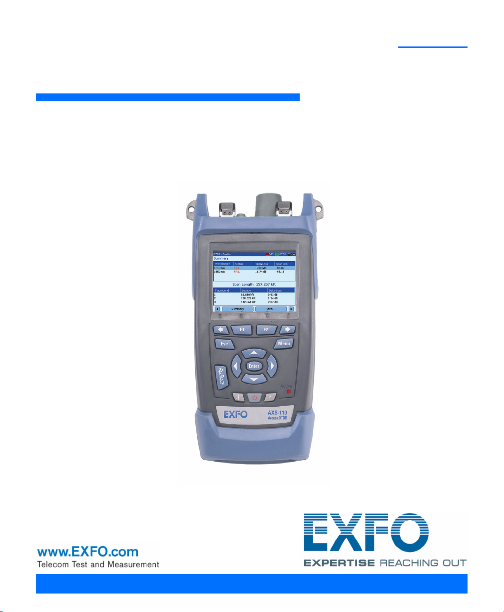
1 Introducing the AXS-100
Series OTDR
The AXS-100 Series OTDR is a compact handheld OTDR optimized for
access/FTTx network testing. The unit can be equipped with optional
power meter, visual fault locator (VFL), and fiber inspection probe.
Main Features
³ Test can be started by pressing a single key
³ Possible to test with acquisition duration as short as 5 seconds
³ One or two OTDR ports (singlemode, multimode, or singlemode live)
³ Screen optimized for outdoor use
³ USB ports (host and client)
³ FTTx software package (optional): macrobend, fault finder, and
pass/fail indicators
³ Network testing (ping and trace route)
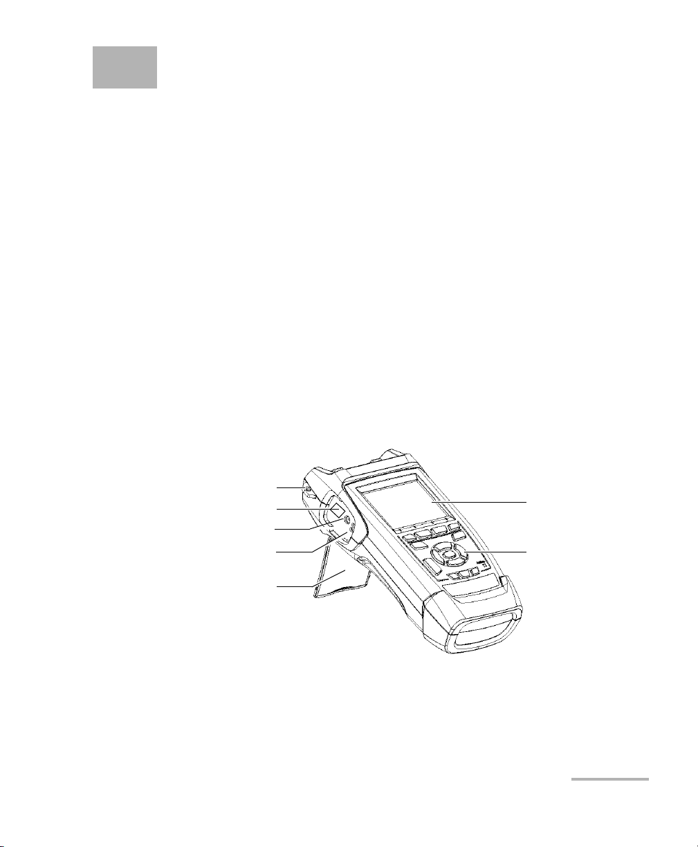
Shoulder strap eyelet
RJ-45 connector
AC adapter/charger connector
Battery charge
status LEDs (one per battery)
Stand
OTDR 1
Display
Keypad
Page 10
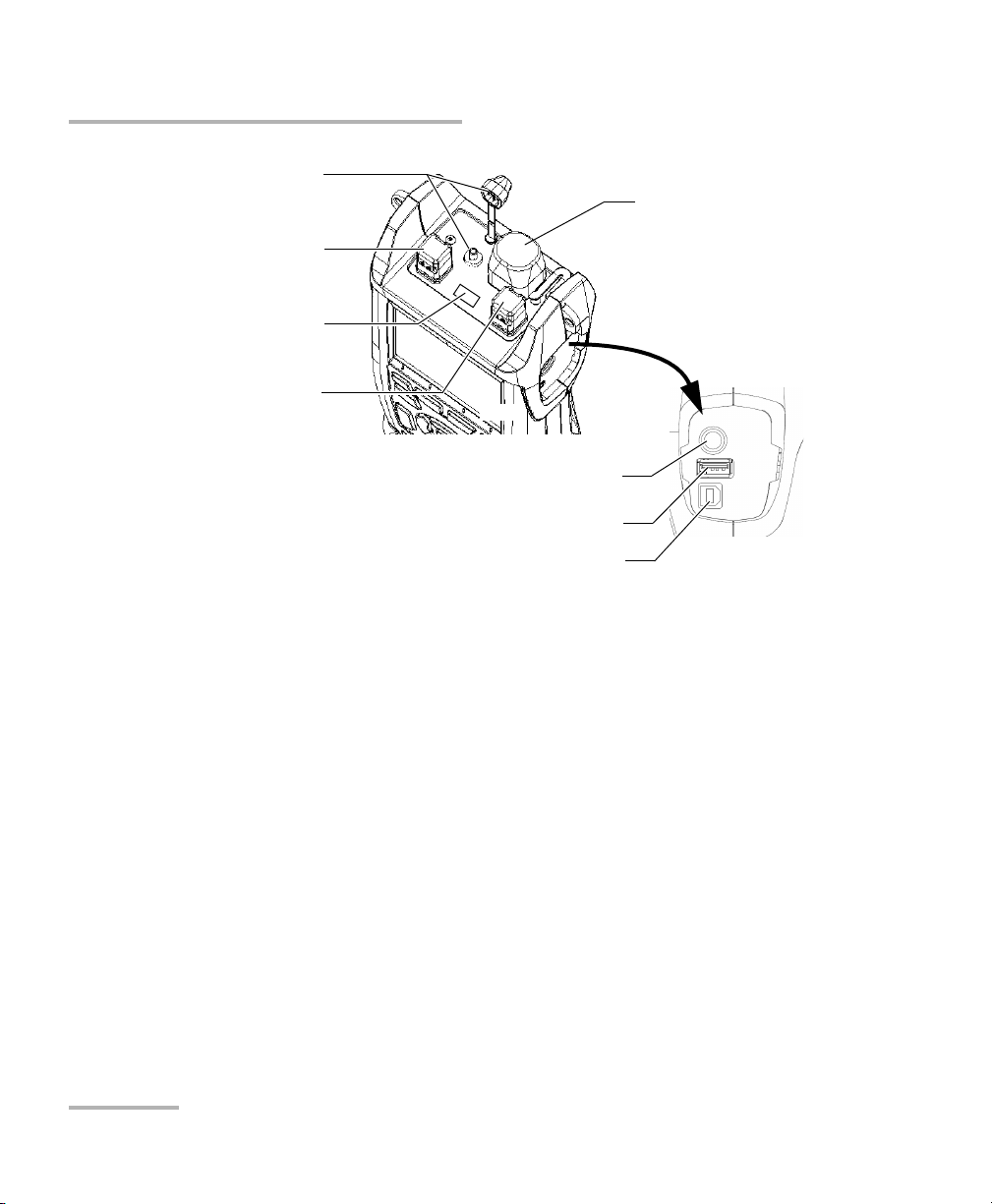
Introducing the AXS-100 Series OTDR
Main Features
Visual fault locator port
and soft cap
Singlemode OTDR port
Infrared port (for printer)
On some models only:
Singlemode live port for
in-service testing
OR
Multimode OTDR port
(for data transfer using memory drive)
(for data transfer via ActiveSync)
Power meter detector port
Inspection probe
connector
USB host port
USB client port
Note: Ports and connectors on your unit may differ from the illustration.
2 AXS-100 Series
Page 11
Introducing the AXS-100 Series OTDR
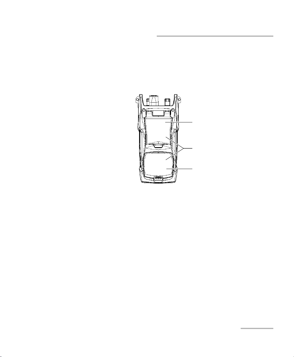
Other test utilities:
³ Visual fault locator to inspect or identify fibers (optional)
³ Video fiber inspection probe (optional)
³ Power meter (optional)
Safety label and serial number
(under the stand)
Quick reference labels
Battery compartment
(two rechargeable batteries)
Main Features
OTDR 3
Page 12

Introducing the AXS-100 Series OTDR
Main Features
Other useful characteristics:
³ Customizable test thresholds with visual pass/fail analysis
³ Memory for 500 OTDR traces and possible data transfer to a computer
³ Energy-saving features: automatic backlight or unit shutdown
³ Multilingual graphical user interface
³ Comprehensive online help available from each function and Quick
Reference labels affixed to back of unit
³ Data post-processing: You can install the OTDR Viewer software
(provided on the installation CD) on a computer to view and analyze
OTDR traces. You can access more features such as:
³ customized printout
³ batch printing
³ conversion of traces to many formats such as Telcordia or ASCII.
4 AXS-100 Series
Page 13

Introducing the AXS-100 Series OTDR
Power Sources
Power Sources
The unit operates with the following power sources:
³ AC adapter/charger (connected to standard power outlet—indoor use
only). Compatible car outlet adapter available upon request.
³ Two lithium-ion rechargeable batteries (automatically take over if you
disconnect the AC adapter/charger). Battery recharge is automatic
when the AC adapter/charger is connected.
Typical Applications
You can use the OTDR for several applications, such as:
³ Short-link testing
³ Service activation
³ Fault finder
³ Troubleshooting (dark and live fibers)
OTDR 5
Page 14

Introducing the AXS-100 Series OTDR
OTDR Basic Principles
OTDR Basic Principles
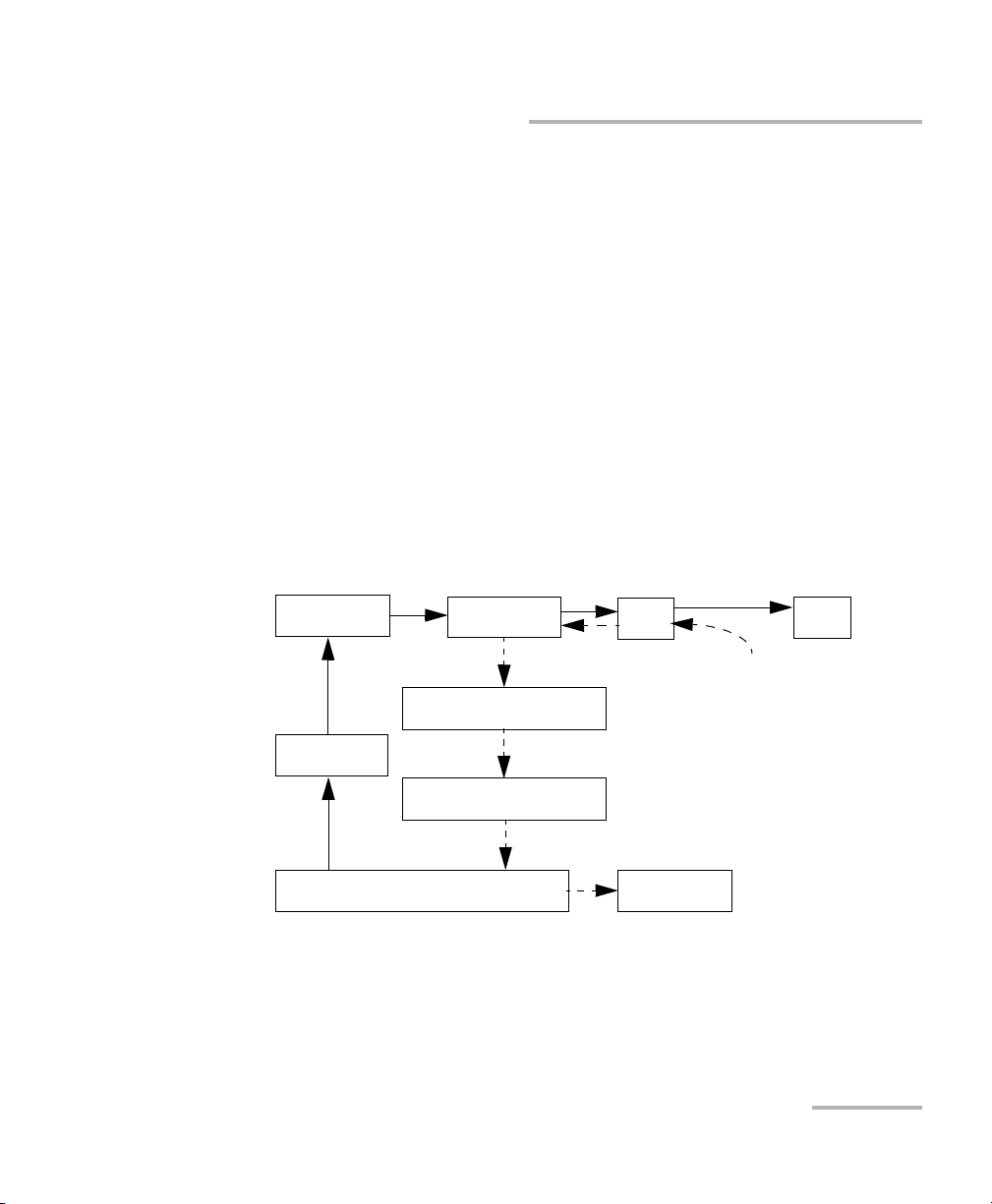
An OTDR sends short pulses of light into a fiber. Light scattering occurs in
the fiber due to discontinuities such as connectors, splices, bends, and
faults. An OTDR then detects and analyzes the backscattered signals. The
signal strength is measured for specific intervals of time and is used to
characterize events.
The OTDR calculates distances as follows:
Distance
Distance
where
c = speed of light in a vacuum (2.998 x 10
t = time delay from the launch of the pulse to the reception of the
pulse
n = index of refraction of the fiber under test (as specified by the
manufacturer)
c
t
-- -
-- -
×=
n
2
8
m/s)
6 AXS-100 Series
Page 15
Introducing the AXS-100 Series OTDR
OTDR Basic Principles
An OTDR uses the effects of Rayleigh scattering and Fresnel reflection to
measure the fiber condition, but the Fresnel reflection is tens of thousands
of times greater in power level than the backscatter.
³ Rayleigh scattering occurs when a pulse travels down the fiber and
small variations in the material, such as variations and discontinuities
in the index of refraction, cause light to be scattered in all directions.
However, the phenomenon of small amounts of light being reflected
directly back toward the transmitter is called backscattering.
³ Fresnel reflections occur when the light traveling down the fiber
encounters abrupt changes in material density that may occur at
connections or breaks where an air gap exists. A very large quantity of
light is reflected, as compared with the Rayleigh scattering. The
strength of the reflection depends on the degree of change in the index
of refraction.
generator
Set of
instructions
Laser
diode
Pulse
Light pulses
Optical
coupler
Returned signal
Avalanche
photodetector (APD)
Analog-to-digital
converter (A/D)
Analyzed signal
Microprocessor
Light pulses
OTDR
port
Reflections coming
Display
Fiber
back to the OTDR
When the full trace is displayed, each point represents an average of many
sampling points. You will have to zoom to see each point (see Using Zoom
Controls on page 59).
OTDR 7
Page 16

Introducing the AXS-100 Series OTDR
Conventions
Conventions
Before using the product described in this manual, you should understand
the following conventions:
Indicates a potentially hazardous situation which, if not avoided,
could result in death or serious injury. Do not proceed unless you
understand and meet the required conditions.
Indicates a potentially hazardous situation which, if not avoided,
may result in minor or moderate injury. Do not proceed unless you
understand and meet the required conditions.
Indicates a potentially hazardous situation which, if not avoided,
may result in component damage. Do not proceed unless you
understand and meet the required conditions.
WARNING
CAUTION
CAUTION
IMPORTANT
Refers to information about this product you should not overlook.
8 AXS-100 Series
Page 17
2 Safety Information
WARNING
Do not install or terminate fibers while a light source is active.
Never look directly into a live fiber and ensure that your eyes are
protected at all times.
WARNING
Use of controls, adjustments and procedures for operation and
maintenance other than those specified herein may result in
hazardous radiation exposure or impair the protection provided by
this unit.
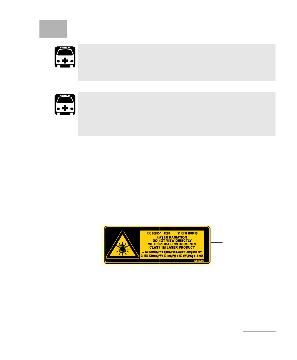
Laser Safety Information (Units without VFL)
Your instrument is a Class 1M laser product in compliance with standards
IEC 60825-1 and 21 CFR 1040.10. Invisible laser radiation may be
encountered at the output port.
The product is safe under reasonably foreseeable conditions of operation
but it may be hazardous if you use optics within a diverging or collimated
beam. Do not view directly with optical instruments.
Affixed to back
(under the stand)
OTDR 9
Page 18
Safety Information
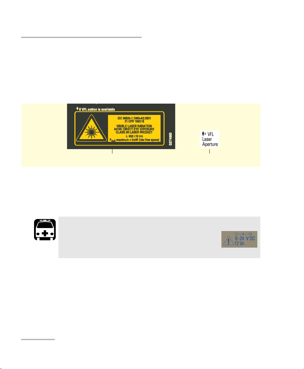
Laser Safety Information (Units with VFL)
Laser Safety Information (Units with VFL)
Your instrument is a Class 3R laser product in compliance with standards
IEC 60825-1 and 21 CFR 1040.10. It is potentially harmful in direct
intrabeam viewing.
The following label(s) indicate that the product contains a Class 3R source:
Affixed to back
(under the stand)
Indicated on
connector panel
Electrical Safety Information
The AC adapter/charger provided with this unit (14.4 W/9 V) is specifically
designed to work with your AXS-100 Series OTDR.
WARNING
Use the AC adapter/charger indoors only.
Any other AC adapter/charger or power source
(for example, car outlet) must output at least 12 W.
10 AXS-100 Series
Page 19

3 Getting Started with Your
OTDR
Turning the Unit On and Off
When you turn the unit on, you may use it immediately under normal
conditions.
When the unit is turned off, it keeps the following parameters in its internal
memory:
³ Test parameters
³ User-defined thresholds
³ Regional, LCD, and energy-saving settings
³ Saved test results
IMPORTANT
If you remove batteries (and the AC adapter/charger is
disconnected), the unit will turn off without saving the above
elements.
OTDR 11
Page 20

Getting Started with Your OTDR
Turning the Unit On and Off
There are two ways to turn off the AXS-100 Series OTDR
³ Suspend: the next time you turn your unit on, you will quickly return to
your work environment.
³ Shutdown: completely cuts power to the unit; the unit will perform a
complete restart routine the next time you use it. You should perform a
shutdown if you do not intend to use your unit for a week or more.
To turn the unit on:
Press . The unit initializes for a few seconds and displays the OTDR
Parameters pane.
To enter the suspend mode:
Hold down the key for about two seconds. Release the key as soon as
you hear a beep.
To perform a shutdown:
Hold down the key for about five seconds. You will hear a first beep;
release the key after you hear a second beep.
12 AXS-100 Series
Page 21
Getting Started with Your OTDR
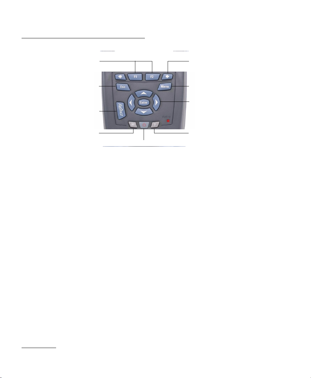
Using Menus and Keypad
Using Menus and Keypad
You can access optical tools from the keypad or menu. Menu options may
differ depending on your unit configuration.
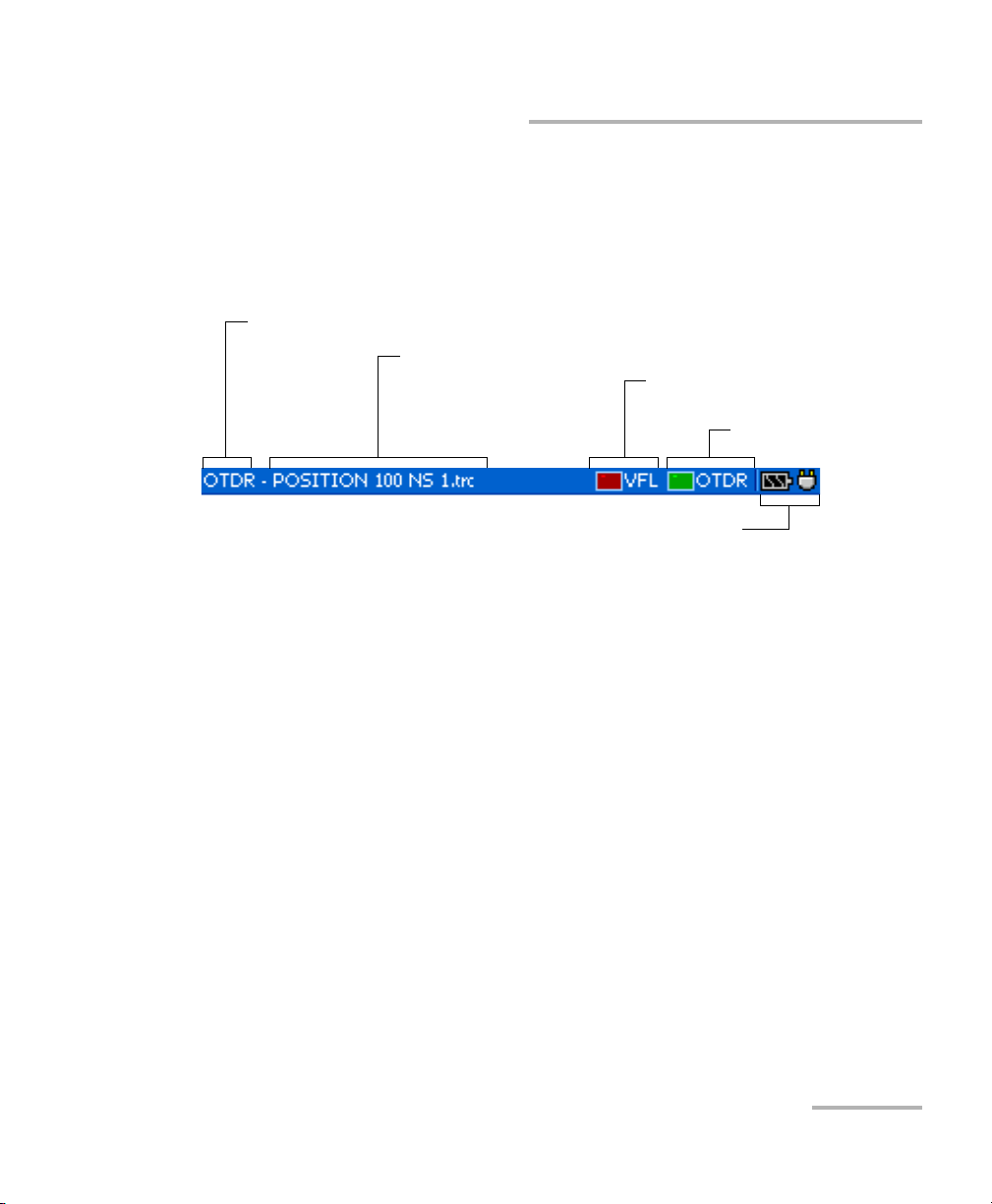
Status Bar
Utility name (OTDR, File Manager, VFL, etc.)
Tra ce na me
VFL status (on/off)
OTDR status
(active/not active)
Battery status and AC adapter/charger status
OTDR 13
Page 22
Getting Started with Your OTDR
Using Menus and Keypad
To activate the function
displayed directly above
Keypad
To scroll through available
functions
To cancel/exit current function
To start (or stop) an acquisition
To adjust brightness (four levels)
To access main features:
1. Press the Menu key.
2. Use the arrows to select a feature and press Enter.
To activate F1/F2 functions:
1. Use the left/right function arrows (on each side of the F1/F2 keys) to
display the desired function or parameter.
2. Press the F1 or F2 key located just below.
To access and modify on-screen parameters:
1. Use the arrows to select an on-screen item (list, check box, etc.).
2. Press Enter to activate or open it.
To enter text or numbers with an on-screen keyboard:
³ Use the left/right function arrows (on each side of the F1/F2 keys) to
move the cursor in the text.
To turn unit on/off
To access the main menu
To move around, select items,
and change parameters
To access help about
current function
³ Use the up/down and left/right arrows to select a character, and then
press Enter to add it.
³ Press OK (F1 key) to accept the element, and then hide the keyboard.
14 AXS-100 Series
Page 23
4 Customizing Your OTDR
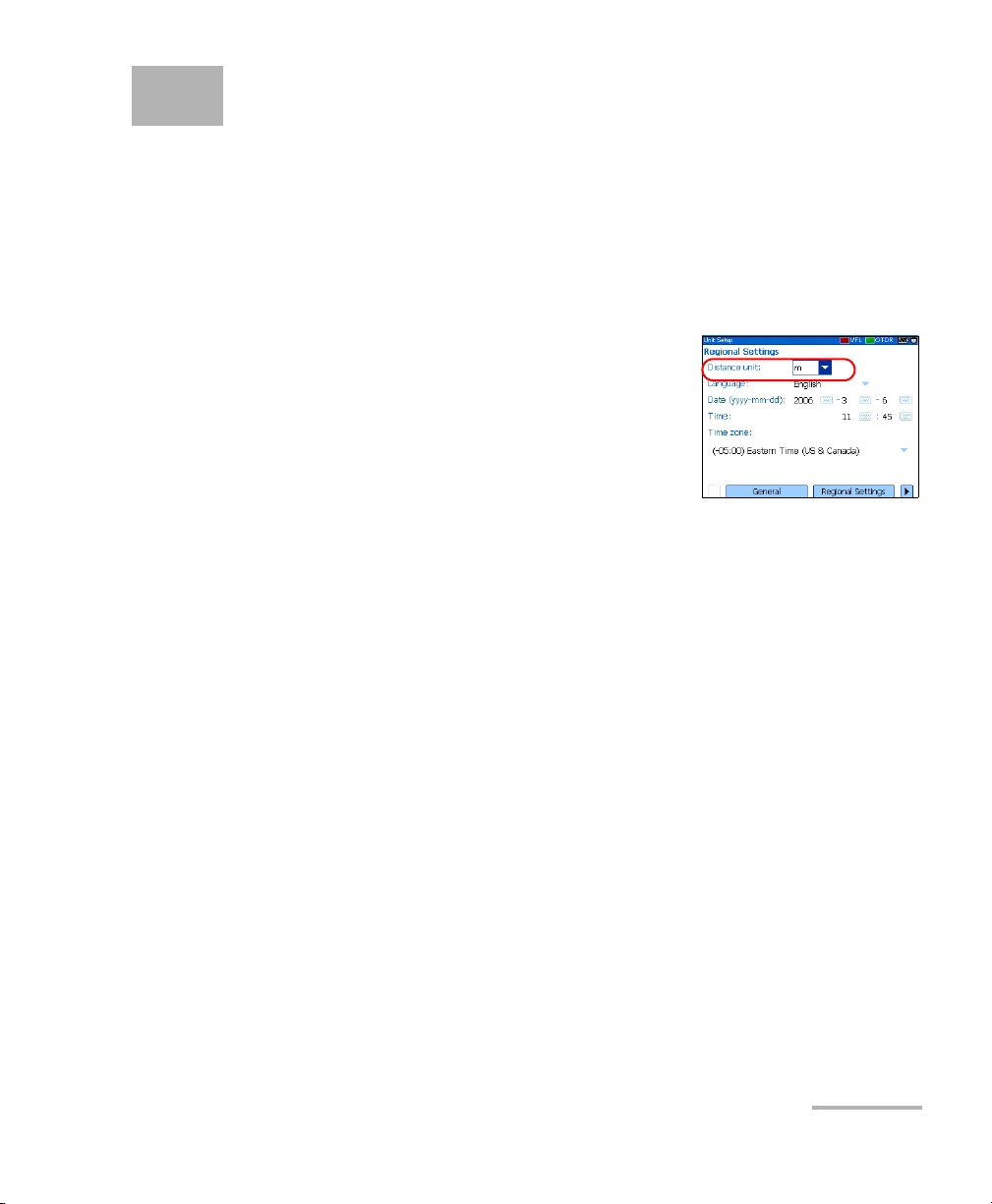
Selecting the Distance Units
There are three distance units available: meters, miles, and kilofeet.
Note: The attenuation values are always expressed in dBs per kilometer.
To select distance units:
1. Press Menu, select Setup > Unit, and then
press Enter.
2. Use the left/right function arrows until you
see Regional Settings, and then press F2 to
display the pane.
3. Press Enter to open the Distance unit list.
4. With the current distance unit highlighted, use the up/down arrows to
select the desired unit, and then press Enter to activate it.
OTDR 15
Page 24
Customizing Your OTDR
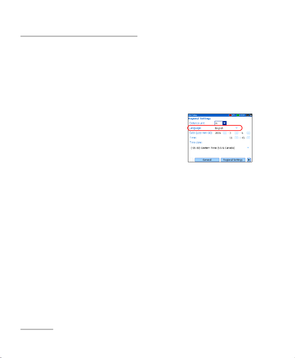
Selecting the Language of Operation
Selecting the Language of Operation
You may display the user interface in one of the available languages
(default is English). If other languages become available in the future, you
could access them by replacing the unit software (see Upgrading the
AXS-100 Series OTDR Software on page 108). Values are kept in memory
when you turn the unit off.
To select a new interface language:
1. Press Menu, select Setup > Unit, and then
press Enter.
2. Use the left/right function arrows until you
see Regional Settings, and then display the
pane (F1/F2 key).
3. Use the up/down arrows to select the
Language list, and then press Enter to open it.
4. With the current language highlighted, use the up/down arrows to
select the desired language, and then press Enter to activate it.
Once you have modified the language, you will be prompted to restart
your unit.
16 AXS-100 Series
Page 25
Customizing Your OTDR
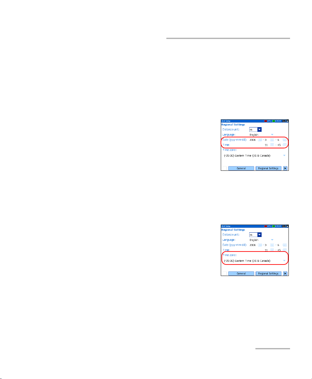
Setting the Date and Time
Setting the Date and Time
When saving results, the unit also saves the corresponding date and time.
You must enter the date according to the year-month-day format and the
time according to the 24-hour format.
You can also modify the time zone.
To set the date and time:
1. Press Menu, select Setup > Unit, and then
press Enter.
2. Use the left/right function arrows until you
see Regional Settings, and then display the
pane (F1/F2 key).
3. Use the arrows to select any of the date or
time settings, and then press Enter to display the on-screen keyboard
(for details about using keyboards, see Using Menus and Keypad on
page 13).
4. Enter the new value and press OK (F1/F2 key).
To modify the time zone:
1. Press Menu, select Setup > Unit, and then
press Enter.
2. Use the left/right function arrows until you
see Regional Settings, and then display the
pane (F1/F2 key).
3. Use the arrows to select the Time zone list,
and then press Enter to open it.
4. With the current time zone highlighted, use the up/down arrows to
select the desired time zone, and then press Enter to activate it.
OTDR 17
Page 26
Customizing Your OTDR
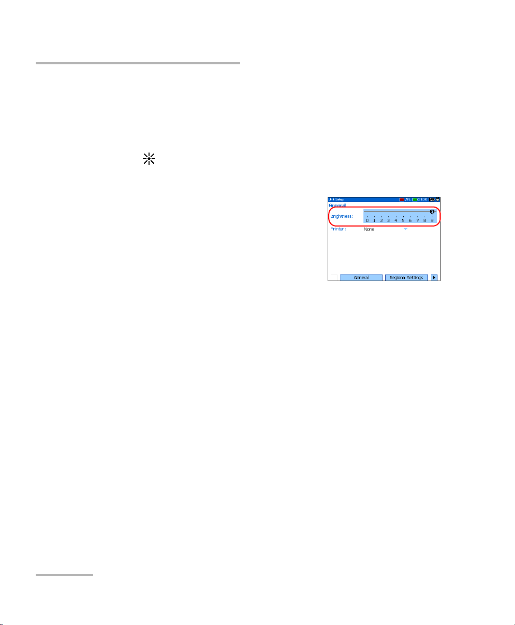
Adjusting the Brightness
Adjusting the Brightness
To fit your work environment, you may adjust the LCD brightness. Values
are kept in memory when you turn the unit off.
To adjust the display brightness:
Press the key repeatedly to switch between brightness levels (0-3-6-9).
OR
1. Press Menu, select Setup > Unit, and then
press Enter.
2. If necessary, use the left/right function
arrows until you see General, and then
display the pane (F1/F2 key).
By default, the Brightness slider is selected.
3. Use the left/right arrows to adjust the brightness level.
18 AXS-100 Series
Page 27
Customizing Your OTDR
Selecting a Printer
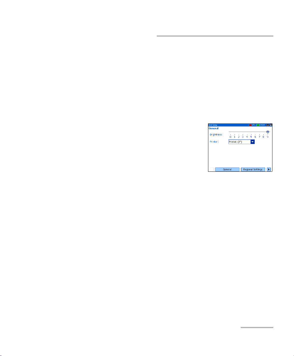
Selecting a Printer
To print reports, you must configure the printer first. Your unit supports the
Printek 2” printer only and communicates with it via the infrared port
located on the top panel.
If you want to print on a network printer or if you want to print other type of
reports, you must transfer the desired files on a computer on which
ToolBox 6 (or later), FastReporter or OTDR Viewer is installed.
To select a printer:
1. Press Menu, select Setup > Unit, and then
press Enter.
2. If necessary, use the left/right function
arrows until you see General, and then
display the pane (F1/F2 key).
3. Use the up/down arrows to select the Printer
list, and then press Enter to open it.
4. With the current printer highlighted, use the up/down arrows to select
the desired printer, and then press Enter to activate it.
OTDR 19
Page 28

Customizing Your OTDR
Configuring the Power Management Settings
Configuring the Power Management Settings
When you do not use the unit for a while, the display may be dimmed to
save power.
You can set idle durations for AC adapter/charger and battery operation.
The unit goes in suspend mode after the specified duration has expired
(see Turning the Unit On and Off on page 11).
Values are kept in memory when you turn the unit off.
Note: When the backlight is dimmed, the unit operation is not interrupted. Press
any key to return to normal operation.
To configure the power management settings:
1. Press Menu, select Setup > Unit, and then
press Enter.
2. Use the left/right function arrows until you
see Power, and then display the pane
(F1/F2 key).
3. Use the up/down arrows to go to the Tur n
off backlight or Turn off unit section.
4. Use the up/down arrows to select the battery or AC adapter/charger
duration list, and then press Enter to open the list.
5. With the current duration highlighted, use the up/down arrows to
select the desired duration (or Never), and then press Enter to confirm.
20 AXS-100 Series
Page 29
5 Setting Up Your OTDR
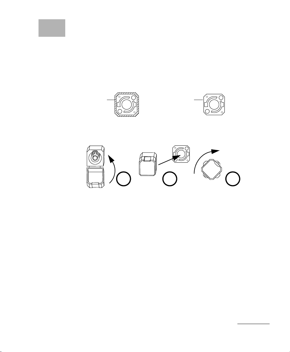
Installing the EXFO Universal Interface (EUI)
The EUIfixed baseplate is available for connectors with angled (APC) or
non-angled (UPC) polishing. A green border around the baseplate
indicates that it is for APC-type connectors.
Green border
indicates APC
option
To install an EUI connector adapter onto the EUI baseplate:
1. Hold the EUI connector adapter so the dust cap opens downwards.
Bare metal
(or blue border)
indicates UPC
option
2 3 4
2. Close the dust cap in order to hold the connector adapter more firmly.
3. Insert the connector adapter into the baseplate.
4. While pushing firmly, turn the connector adapter clockwise on the
baseplate to lock it in place.
OTDR 21
Page 30

Setting Up Your OTDR
Cleaning and Connecting Optical Fibers
Cleaning and Connecting Optical Fibers
To ensure maximum power and to avoid erroneous readings:
³ Always inspect fiber ends and make sure that they are clean as
explained below before inserting them into the port. EXFO is
not responsible for damage or errors caused by bad fiber
cleaning or handling.
³ Ensure that your patchcord has appropriate connectors. Joining
mismatched connectors will damage the ferrules.
To connect the fiber-optic cable to the port:
1. Inspect the fiber using a fiber inspection microscope. If the fiber is
clean, proceed to connecting it to the port. If the fiber is dirty, clean it as
explained below.
2. Clean the fiber ends as follows:
IMPORTANT
2a. Gently wipe the fiber end with a lint-free swab dipped in isopropyl
alcohol.
2b. Use compressed air to dry completely.
2c. Visually inspect the fiber end to ensure its cleanliness.
22 AXS-100 Series
Page 31

Setting Up Your OTDR
Cleaning and Connecting Optical Fibers
3. Carefully align the connector and port to prevent the fiber end from
touching the outside of the port or rubbing against other surfaces.
If your connector features a key, ensure that it is fully fitted into the
port’s corresponding notch.
4. Push the connector in so that the fiber-optic cable is firmly in place,
thus ensuring adequate contact.
If your connector features a screwsleeve, tighten the connector
enough to firmly maintain the fiber in place. Do not overtighten, as this
will damage the fiber and the port.
Note: If your fiber-optic cable is not properly aligned and/or connected, you will
notice heavy loss and reflection.
OTDR 23
Page 32

Setting General OTDR Parameters
Setting General OTDR Parameters
You can set preferences such as:
³ Grid: You can display or hide the grid appearing on the graph’s
background. By default, the grid is displayed.
³ Zoom and markers: You can display or hide the zoom controls as well
as the markers appearing on the graph.
³ Automatic zoom on fiber span: You can set the trace display to show
only the portion of the trace that is located between the span start and
the span end, in full-trace view. By default, this feature is selected.
Even if the application automatically zooms in on the fiber span, you
can adjust the zoom manually. You can even zoom in on events
located outside the fiber span. For more information on how to use the
zoom controls, see Using Zoom Controls on page 59.
³ Reference file: You can enable or disable the selection of a reference
trace. A reference trace is used to compare fibers of a same cable,
monitor fiber deterioration, or compare fibers before and after
installation. This trace appears in red on the graph.
³ Summary pane (available only with the optional FTTx software
package): By default, the Summary pane is automatically displayed as
soon as an acquisition is complete. You can disable this automatic
display (you can always access it via the Summary button from the
OTDR pane.)
³ Event (fiber) sections: You can display or hide event (fiber) sections in
the Events pane, depending on the types of values you want to view. If
you display event sections, the Events pane will include section length
and section attenuation.
For example, by hiding the event (fiber) sections, you can obtain the
running total of connector and splice losses instead of having a loss
value for the entire link. Information on event sections is also available
from the Trace pane, in the events table located just below the graph.
24 AXS-100 Series
Page 33

Setting General OTDR Parameters
To set the general OTDR parameters:
1. Press Menu, select Setup > OTDR, and then
press Enter.
2. Display the General pane (F1/F2 key).
3. Use the up/down arrows to highlight the
desired item, and then press Enter to
select it.
You can press Enter one more time to clear the boxes.
To revert to the factory-default settings:
1. Press Menu, select Setup > OTDR, and then press Enter.
2. From the General pane, use the arrows to select Default, and then
press Enter to confirm.
OTDR 25
Page 34

Setting the Acquisition Parameters
Setting the Acquisition Parameters
You can set parameters such as IOR (group index), backscatter, and helix
factor. You can also enable or disable the first connector check.
Setting the IOR, Backscatter, and Helix Factor
Your unit contains default IOR (group index), backscatter, and helix factor
values that you can modify if they do not suit your testing needs. You
should set the IOR (group index), backscatter, and helix factor before
performing tests in order to apply them to all newly acquired traces.
³ The index of refraction (IOR) (also known as group index) is used to
convert time-of-flight to distance. Having the proper IOR is crucial for
all OTDR measurements associated with distance (event position,
attenuation, total length, etc.). IOR is provided by the cable or fiber
manufacturer.
³ The (Rayleigh) backscatter value represents the amount of backscatter
in a particular fiber. The backscatter is used in the calculation of ORL
and reflectance, and it can usually be obtained from the cable
manufacturer.
³ The helix factor takes into account the difference between the length
of the cable and the length of the fiber inside the cable; it does not vary
with wavelengths.
The length of the OTDR distance axis is always equivalent to the
physical length of the cable (not the fiber).
26 AXS-100 Series
Page 35

Setting the Acquisition Parameters
To set the IOR, backscatter, and helix factor parameters:
1. Press Menu, select Setup > OTDR, and then
press Enter.
2. Display the Acquisition pane (F1/F2 key).
3. Use the up/down arrows to select the
wavelength box, and then press Enter to
open it.
4. Select the wavelength for which you want to modify parameters. Press
Enter to confirm your choice.
5. Use the arrows to select any of the settings, and then press Enter to
display the on-screen keyboard (for details about using keyboards, see
Using Menus and Keypad on page 13).
IMPORTANT
Do not change the default backscatter parameter unless you have
values provided by the fiber manufacturer. If you set this parameter
incorrectly, your reflectance measurements will be inaccurate.
6. Enter the new value and press OK (F1/F2 key).
As you enter the value, the application indicates the minimum or
maximum value allowed.
OTDR 27
Page 36

Setting the Acquisition Parameters
Enabling or Disabling the First Connector Check
The first connector check feature is used to verify that the fibers are
properly connected to the OTDR. It verifies the injection level and the
reflectance of the first connector. It displays a message when a unusually
high loss or reflectance occur at the first connection.
You enable or disable this feature for all wavelengths at a time.
To enable or disable the first connector check:
1. Press Menu, select Setup > OTDR, and then
press Enter.
2. Display the Acquisition pane (F1/F2 key).
3. Use the up/down arrows to highlight First
connector check, and then press Enter to
select it.
You can press Enter one more time to clear the box.
Reverting to Factory-Default Acquisition Settings
You can revert to factory settings at any time. The IOR (group index),
backscatter, and helix factor will be reset and the first connector check
feature will be disabled.
To revert to factory-default settings:
1. Press Menu, select Setup > OTDR, and then press Enter.
2. From the Acquisition pane, use the arrows to select Default, and then
press Enter.
3. When the application prompts you, answer Yes (F1/F2 key).
28 AXS-100 Series
Page 37

Setting Analysis Parameters
Setting Analysis Parameters
³ To define the actual fiber span start, you can set the launch fiber length.
When you perform tests with your unit, you connect a launch fiber
between your unit and the fiber under test. This is why, by default, the
fiber span includes the launch fiber.
When you define the length of the launch fiber, the application sets the
fiber span start at the beginning of the fiber under test. Therefore, only
events related to the defined fiber span will be taken into account. The
application will include the loss caused by the span start event in the
displayed values. The span start event will also be taken into account
when determining the status (pass/fail) of connector loss and
reflectance.
The span start becomes event 1 and its distance reference becomes 0.
Events excluded from the fiber span are shaded in the event table, and
do not appear in the trace display. The cumulative loss is calculated for
the defined fiber span only.
³ To optimize event detection, you can set the following detection
thresholds:
³ Splice loss threshold: To display or hide small non-reflective events.
³ Reflectance threshold: To hide false reflective events generated by
noise, transform non-harmful reflective events into loss events, or
detect reflective events that could be harmful to network and other
fiber-optic equipment.
³ End-of-fiber threshold: To stop the analysis as soon as an important
loss event occurs; for example, an event that could compromise
signal transmission down to the end of a network.
OTDR 29
Page 38

Setting Analysis Parameters
To set analysis parameters:
1. Press Menu, select Setup > OTDR, and then
press Enter.
2. Display the Analysis pane (F1/F2 key).
3. Use the arrows to select any of the settings,
and then press Enter to display the on-screen
keyboard (for details about using keyboards,
see Using Menus and Keypad on page 13).
4. Enter the new value and press OK (F1/F2 key).
As you enter the value, the application indicates the minimum or
maximum value allowed.
To revert to the factory-default settings:
1. Press Menu, select Setup > OTDR, and then press Enter.
2. From the Acquisition pane, use the arrows to select Default, and then
press Enter.
30 AXS-100 Series
Page 39

Setting Pass/Fail Thresholds
Setting Pass/Fail Thresholds
Note: This function is available only with the optional FTTx software package.
You can enable and set pass/fail threshold parameters for your tests.
You can define thresholds to specify acceptable values (in dB) for splice
loss, connector loss, reflectance, span loss and span ORL, and this, for
each wavelength.
Each time a measurement exceeds a threshold, the result appears in white
on a red background in the Summary pane preceded by the word “FAIL”,
also in red. Values appearing in the event table will also be displayed in
white on a red background.
OTDR 31
Page 40

Setting Pass/Fail Thresholds
To set pass/fail thresholds:
1. Press Menu, select Setup > OTDR, and then
press Enter.
2. Use the left/right function arrows until you
see Pass/Fail Thresholds, and then display
the pane (F1/F2 key).
3. Press Enter to open the wavelength list.
4. Use the up/down arrows to select the desired wavelength. Press Enter
to confirm your choice.
5. Use the up/down arrows to highlight the desired threshold name.
If necessary, press Enter to select the check box. If you clear the check
box, the application will not use the threshold.
6. Use the arrows to highlight the threshold value, and then press Enter to
display the on-screen keyboard (for details about keyboards, see Using
Menus and Keypad on page 13).
7. Set the threshold.
As you enter the value, the application indicates the minimum or
maximum value allowed.
8. Press OK (F1/F2 key) to hide the keyboard.
To revert to the factory-default settings:
1. Press Menu, select Setup > OTDR, and then press Enter.
2. From the Pass/Fail Thresholds pane, use the arrows to select Default,
and then press Enter.
3. When the application prompts you, answer Yes (F1/F2 key).
32 AXS-100 Series
Page 41

Setting Macrobend Parameters
Setting Macrobend Parameters
Note: This function is available only with the optional FTTx software package.
Your unit can locate macrobends by comparing the loss values measured
at a certain location, for a certain wavelength (for example, 1310 nm) with
the loss values measured at the corresponding location, but for a greater
wavelength (for example, 1550 nm).
The unit will identify a macrobend when comparing two loss values if:
³ Of the two loss values, the greater loss occurred at the greater
wavelength.
AND
³ The difference between the two loss values exceeds the defined delta
loss value. The default delta loss value is 0.5 dB (which is suitable for
most fibers) but you can modify it.
You can also disable macrobend detection.
Note: Macrobend detection is only possible with singlemode wavelengths.
OTDR 33
Page 42

Setting Macrobend Parameters
To set macrobend parameters:
1. Press Menu, select Setup > OTDR, and then
press Enter.
2. Display the Macrobend pane (F1/F2 key).
3. If necessar y, press Enter to select the Display
macrobend check box.
If you clear the check box, the application
will not detect macrobends.
4. Press Enter to open the Wavelengths list.
5. Use the up/down arrows to select the desired wavelengths. Press Enter
to confirm your choice.
6. Use the arrows to highlight the Delta (dB) value, and then press Enter
to display the on-screen keyboard (for details about keyboards, see
Using Menus and Keypad on page 13).
7. Set the delta (loss difference) value.
As you enter the value, the application indicates the minimum or
maximum value allowed.
8. Press OK (F1/F2 key) to hide the keyboard.
34 AXS-100 Series
Page 43

Setting Storage Parameters
Setting Storage Parameters
Each time you save a trace, the unit suggests a file name based on
autonaming settings. After saving a result, the unit prepares the next file
name by incrementing the suffix.
File names: maximum of 20 characters for prefix and 3 digits for suffix.
By default, traces are saved in native (.trc) format, but you can configure
your unit to save them in Bellcore (.sor) format.
Note: If you select the Bellcore (.sor) format, the unit will create one trace file per
wavelength (for example, TRACE001_1310.sor and TRACE001_1550.sor, if
you selected both 1310 nm and 1550 nm for your test). The native format
contains all wavelengths in a single trace file.
To set the autonaming scheme:
1. Press Menu, select Setup > OTDR, and then press Enter.
2. Use the left/right function arrows until you see Storage, and then
display the pane (F1/F2 key).
3. Use the up/down arrows to select File name prefix or File name
suffix.
4. Press Enter to display the on-screen keyboard.
5. Enter the name (prefix) or number (suffix), and then press OK
(F1/F2 key) to hide the keyboard.
OTDR 35
Page 44

Setting Storage Parameters
To set the file format:
1. Press Menu, select Setup > OTDR, and then press Enter.
2. Use the left/right function arrows until you see Storage, and then
display the pane (F1/F2 key).
3. Use the arrows to select Default file format, and then press Enter to
open the list.
4. Use the up/down arrows to select the desired format, and then press
Enter to confirm.
To revert to the factory-default for file format and autonaming
scheme:
1. Press Menu, select Setup > OTDR, and then press Enter.
2. Use the left/right function arrows until you see Storage, and then
display the pane (F1/F2 key).
3. Use the up/down arrows to select Default, and then press Enter to
confirm.
36 AXS-100 Series
Page 45

6Testing Fibers
The OTDR offers different test modes:
³ Auto: sets all test parameters, performs tests at the specified
wavelengths, and provides complete results.
³ Fault finder: rapidly locates fiber ends and displays length of the fiber
under test. This function is available only with the optional FTTx
software package.
³ Manual (advanced): offers all the tools you need to perform complete
OTDR tests and measurements manually and gives you control over all
test parameters.
³ Real time: enables to view sudden changes in the fiber link. In this
mode, trace is refreshed instead of averaged.
You can start a test from any pane by pressing the F
will use the current parameters. You can stop a test by pressing the
F
ASTRACE key one more time.
Your unit may be equipped with two OTDR ports:
³ OTDR SM port: singlemode port to perform conventional OTDR tests
on dark fibers.
³ OTDR MM port (optional): multimode port to perform conventional
OTDR tests on dark fibers.
OR
³ OTDR SM Live port (optional): singlemode filtered port with
out-of-band wavelength to perform troubleshooting tests on live fibers.
ASTRACE key. The unit
OTDR 37
Page 46

Testing Fibers
Testing in Auto Mode
Testing in Auto Mode
The application will automatically evaluate the best settings according to
the fiber link currently connected to the unit (in less than 5 seconds).
By default, fiber characteristics are evaluated each time you start a test.
This is particularly useful if you often have to test fiber links of different
lengths.
If you prefer, you can set your unit to keep the same settings (range and
pulse) for all acquisitions. This could be useful if you need to test several
similar fibers (same length) within the same cable. It is always possible to
reset the fiber settings later.
If you intend to test at multimode wavelengths, carefully read Launch
Conditions for Multimode Measurements on page 50.
38 AXS-100 Series
Page 47

Testing Fibers
Testing in Auto Mode
To acquire traces in Auto mode:
1. Clean the connectors properly (see Cleaning and Connecting Optical
Fibers on page 22).
2. Connect a launch fiber between the device under test and the OTDR
port. If necessary, set the launch fiber length (see Setting Analysis
Parameters on page 29).
If your unit is equipped with two OTDR ports, ensure that you connect
the fiber to the appropriate port (singlemode, singlemode live, or
multimode), depending on the wavelength you intend to use.
CAUTION
Never connect a live fiber to the OTDR port without a proper setup.
Any incoming optical power ranging from –65 dBm to –40 dBm will
affect the OTDR acquisition. The way the acquisition will be
affected depends on the selected pulse width.
Any incoming signal greater than –20 dBm could damage your
OTDR permanently. For live-fiber testing, refer to the SM Live port
specifications for the characteristics of the built-in filter.
3. Press Menu, select OTDR, and then press Enter.
OTDR 39
Page 48

Testing Fibers
Testing in Auto Mode
4. Use the left/right function arrows until you see Parameters, and then
5. Select the test mode as follows:
6. Select test wavelengths as follows:
7. Select duration of the acquisition as follows:
display the pane (F1/F2 key).
5a. Use the arrows to select the OTDR
mode list, and then press Enter to open
the list.
5b. Use the up/down arrows to select Auto,
and then press Enter to confirm.
6a. If your OTDR supports singlemode, singlemode live, or multimode
wavelengths, under Wavelength, from the list, select the desired
fiber type (for live-fiber testing, select SM Live; for C fiber, select
50 μm and for D fiber, select 62.5 μm).
6b. Use the arrows to select the desired wavelengths and press Enter
to confirm each selection.
7a. Use the arrows to select the Duration list, and then press Enter to
open it.
7b. Use the up/down arrows to select the desired duration for the
acquisition, and then press Enter to confirm.
40 AXS-100 Series
Page 49

Testing Fibers
Testing in Auto Mode
8. Specify whether the unit must keep the fiber settings for all acquisitions
or not, as follows:
8a. Use the arrows to select the Keep parameters list, and then press
Enter to open it.
8b. If you want the unit to reset the settings for each acquisition,
select No.
OR
If you want the unit to always use the same parameters, select
Yes.
8c. Press Enter to confirm.
Note: Even if you configured the unit to keep the parameters, it is possible to reset
the fiber settings by selecting No, and then starting an acquisition. If
desired, you can set back the option to Ye s to use the new settings for the
next acquisitions.
9. Press F
You can stop the acquisition at any time by pressing F
ASTRACE to start the acquisition.
ASTRACE once
again.
OTDR 41
Page 50

Testing Fibers
Testing in Fault Finder Mode
Testing in Fault Finder Mode
Note: This function is available only with the optional FTTx software package.
The application offers you a special testing feature to rapidly locate fiber
ends. It also displays the length of the fiber under test.
The unit will determine the more appropriate wavelength (singlemode or
multimode, depending on your test configuration). Duration of the
acquisition is 45 seconds.
If you intend to test at multimode wavelengths, carefully read Launch
Conditions for Multimode Measurements on page 50.
To acquire traces in Fault finder mode:
1. Clean the connectors properly (see Cleaning and Connecting Optical
Fibers on page 22).
2. Connect a launch fiber between the device under test and the OTDR
port. If necessary, set the launch fiber length (see Setting Analysis
Parameters on page 29).
If your unit is equipped with two OTDR ports, ensure that you connect
the fiber to the appropriate port (singlemode, singlemode live, or
multimode), depending on the wavelength you intend to use.
CAUTION
Never connect a live fiber to the OTDR port without a proper setup.
Any incoming optical power ranging from –65 dBm to –40 dBm will
affect the OTDR acquisition. The way the acquisition will be
affected depends on the selected pulse width.
Any incoming signal greater than –20 dBm could damage your
OTDR permanently. For live-fiber testing, refer to the SM Live port
specifications for the characteristics of the built-in filter.
3. Press Menu, select OTDR, and then press Enter.
42 AXS-100 Series
Page 51

Testing Fibers
Testing in Fault Finder Mode
4. Use the left/right function arrows until you see Parameters, and then
display the pane (F1/F2 key).
5. Select the test mode as follows:
5a. Use the arrows to select the OTDR
mode list, and then press Enter to open
it.
5b. Use the up/down arrows to select Fault
finder, and then press Enter to confirm.
6. If your OTDR supports singlemode, singlemode live, or multimode
wavelengths, under Wavelength, from the list, select the desired fiber
type (for live-fiber testing, select SM Live; for C fiber, select 50 μm and
for D fiber, select 62.5 μm).
7. Press F
ASTRACE to start the acquisition.
You can stop the acquisition at any time by pressing F
again.
ASTRACE once
OTDR 43
Page 52

Testing Fibers
Testing in Manual (Advanced) Mode
Testing in Manual (Advanced) Mode
You can set distance range, pulse, and duration of the acquisition in this
mode.
Note: Not all pulse widths are compatible with all wavelengths.
If you intend to test at multimode wavelengths, carefully read Launch
Conditions for Multimode Measurements on page 50.
To acquire traces in Manual (Advanced) mode:
1. Clean the connectors properly (see Cleaning and Connecting Optical
Fibers on page 22).
2. Connect a launch fiber between the device under test and the OTDR
port. If necessary, set the launch fiber length (see Setting Analysis
Parameters on page 29).
If your unit is equipped with two OTDR ports, ensure that you connect
the fiber to the appropriate port (singlemode, singlemode live, or
multimode), depending on the wavelength you intend to use.
CAUTION
Never connect a live fiber to the OTDR port without a proper setup.
Any incoming optical power ranging from –65 dBm to –40 dBm will
affect the OTDR acquisition. The way the acquisition will be
affected depends on the selected pulse width.
Any incoming signal greater than –20 dBm could damage your
OTDR permanently. For live-fiber testing, refer to the SM Live port
specifications for the characteristics of the built-in filter.
3. Press Menu, select OTDR, and then press Enter.
44 AXS-100 Series
Page 53
Testing Fibers
Testing in Manual (Advanced) Mode
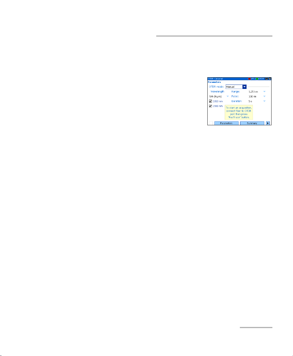
4. Use the left/right function arrows until you see Parameters, and then
display the pane (F1/F2 key).
5. Select the test mode as follows:
5a. Use the arrows to select the OTDR
mode list, and then press Enter
to open it.
5b. Use the up/down arrows to select
Manual, and then press Enter to
confirm.
6. Select test wavelengths as follows:
6a. If your OTDR supports singlemode, singlemode live, or multimode
wavelengths, under Wavelength, from the list, select the desired
fiber type (for live-fiber testing, select SM Live; for C fiber, select
50 μm and for D fiber, select 62.5 μm).
6b. Use the arrows to select the desired wavelengths. Press Enter to
confirm each selection.
7. Select range as follows:
7a. Use the arrows to select the Range list, and then press Enter to
open the list.
7b. Use the up/down arrows to select the desired distance range, and
then press Enter to confirm.
OTDR 45
Page 54

Testing Fibers
Testing in Manual (Advanced) Mode
8. Select pulse as follows:
8a. Use the arrows to select the Pulse list and press Enter to open the
list.
8b. Use the up/down arrows to select the desired pulse, and then
press Enter.
9. Select duration of the acquisition as follows:
9a. Use the arrows to select the Duration list, and then press Enter to
open the list.
9b. Use the up/down arrows to select the desired duration for the
acquisition, and then press Enter to confirm.
10. Press F
ASTRACE to start the acquisition.
You can stop the acquisition at any time by pressing F
again.
ASTRACE once
46 AXS-100 Series
Page 55

Testing Fibers
Monitoring Fiber in Real Time Mode
Monitoring Fiber in Real Time Mode
You can monitor fiber at one wavelength at a time. You can also switch
from Real time mode to Manual mode at any time.
If you intend to test at multimode wavelengths, carefully read Launch
Conditions for Multimode Measurements on page 50.
To monitor fiber in Real time mode:
1. Clean the connectors properly (see Cleaning and Connecting Optical
Fibers on page 22).
2. Connect a launch fiber between the device under test and the OTDR
port. If necessary, set the launch fiber length (see Setting Analysis
Parameters on page 29).
If your unit is equipped with two OTDR ports, ensure that you connect
the fiber to the appropriate port (singlemode, singlemode live, or
multimode), depending on the wavelength you intend to use.
CAUTION
Never connect a live fiber to the OTDR port without a proper setup.
Any incoming optical power ranging from –65 dBm to –40 dBm will
affect the OTDR acquisition. The way the acquisition will be
affected depends on the selected pulse width.
Any incoming signal greater than –20 dBm could damage your
OTDR permanently. For live-fiber testing, refer to the SM Live port
specifications for the characteristics of the built-in filter.
3. Press Menu, select OTDR, and then press Enter.
4. Use the left/right function arrows until you see Parameters and display
the pane (F1/F2 key).
OTDR 47
Page 56

Testing Fibers
Monitoring Fiber in Real Time Mode
5. Select the test mode as follows:
5a. Use the arrows to select the OTDR
mode list and press Enter to open the
list.
5b. Use the up/down arrows to select Real
time, and then press Enter to confirm.
6. Select test wavelengths as follows:
6a. If your OTDR supports singlemode, singlemode live, or multimode
wavelengths, under Wavelength, from the list, select the desired
fiber type (for live-fiber testing, select SM Live; for C fiber, select
50 μm and for D fiber, select 62.5 μm).
6b. Use the arrows to select the desired wavelength. Press Enter to
select it.
48 AXS-100 Series
Page 57

Testing Fibers
Monitoring Fiber in Real Time Mode
7. Select range as follows:
7a. Use the arrows to select the Range list, and then press Enter to
open the list.
7b. Use the up/down arrows to select the desired distance range, and
then press Enter to confirm.
8. Select pulse as follows:
8a. Use the arrows to select the Pulse list, and then press Enter to
open the list.
8b. Use the up/down arrows to select the desired pulse, and then
press Enter to confirm.
9. Press F
ASTRACE to start the acquisition.
To deactivate the Real time mode:
If you only want to stop monitoring, press F
ASTRACE once again.
OR
If you are ready to start a test, proceed as follows:
1. Press Esc to exit the Trace pane.
2. In the displayed panel, open the OTDR mode list, and then select
Manual.
OTDR 49
Page 58

Testing Fibers
Launch Conditions for Multimode Measurements
Launch Conditions for Multimode
Measurements
In a multimode fiber network, the attenuation of a signal is highly
dependent on the mode distribution (or launch condition) of the source
that emits this signal.
In the same way, the attenuation reading performed by any test instrument
will also depend on the mode distribution of its light source.
A single light source cannot be conditioned for both 50 μm (50 MMF) and
62.5 μm (62.5 MMF) fibers at the same time:
³ A source conditioned for 50 MMF testing will be under-filled for
62.5 MMF testing.
³ A source conditioned for 62.5 MMF will be overfilled for 50 MMF testing.
TIA/EIA-455-34A (FOTP34, Method A2) is providing a target launch
condition that is obtained when using an overfilled source followed by
mandrel-wrap mode filter (five close-wound turns around a mandrel tool
of a given diameter).
Your unit has been conditioned for 62.5 MMF testing. However, you can
also test with 50 MMF fibers.
50 AXS-100 Series
Page 59

Testing Fibers
Launch Conditions for Multimode Measurements
The table on fiber types gives information about tests with the 50 μm and
62.5 μm fibers.
Fiber type Recommended mode filter Remarks
50 μm Perform a five-turn
mandrel-wrap (wrapping the
patchcord a minimum of five
turns around the mandrel tool)
on the patchcord connecting
the OTDR to the fiber under
test.
As per FOTP-34:
³ For fibers with 3 mm
jacket: use a mandrel tool
with a diameter of 25 mm.
³ For fibers without jacket:
use a mandrel tool with a
diameter of 22 mm.
62.5 μm No mode filter required. Loss measurements similar to
Nominal launch conditions are
overfilled.
Loss measurements can be
slightly pessimistic (higher loss)
when compared to loss
measurements done with a
50 MMF source compliant to
FOTP34, Method A2.
those obtained with a power
meter and a source that is
conditioned according to
FOTP34, Method A2.
IMPORTANT
If you test with 50-μm fibers, EXFO recommends that you use a
mode filter (mandrel-wrap). Otherwise, you may obtain results with
an excess loss value of 0.1 to 0.3 dB.
OTDR 51
Page 60

Page 61

7 Managing Test Results
There are many ways to view the results:
³ Summary pane
³ Events pane
³ Tra c e pane
³ Trace Info. (trace information) pane
Summary Pane
This pane is displayed once the test is complete if you selected the
corresponding feature (see Setting General OTDR Parameters on page 24).
You can also select Summary (F1/F2 keys).
Pass/Fail status of fiber under test Length of fiber under test
Tested wavelengths
You can select an item with the
Information on
detected macrobends
up/down arrows and press
Enter to switch to Trace pane.
OTDR 53
Page 62

Managing Test Results
Events Pane
Events Pane
This pane shows the list of events found during the test.
You can select Events (F1/F2 keys) to display the pane. Values appearing in
white on a red background exceed the defined thresholds.
Wavelength of the displayed trace
Use left/right arrows to switch
between the different
Event type (see Description of
Event Types on page 127
wavelengths
You can select an item
with up/down arrows
and press Enter to
)
switch to Tra ce pane.
54 AXS-100 Series
Page 63

Managing Test Results
Trace Pane
Trace Pane
You can select Trace (F1/F2 keys) to display the pane. Reflectance and loss
values appear in white on a red background when they exceed the defined
thresholds.
Wavelength of the displayed
Events (use up/down
arrows to view them in
turn)
Distance between span start and markers A and B
trace
Relative power at markers A and B (use
left/right arrows to move markers)
Loss difference between markers A and B
Distance between markers A and B
Reflectance value
Loss value
OTDR 55
Page 64

Managing Test Results
Trace Info. Pane
Trace Info. Pane
After acquiring a trace, you might want to view details about the
acquisition. You can also include information about the tested fiber and job
or add comments. This information is saved along with the trace.
Some of the information is common to all wavelengths (location A and B,
cable ID and fiber ID). Some other is specific to the current wavelength
(job ID, customer and comments).
If you add or delete information from the Trace Info. pane, the common
information will be modified for all wavelengths. However, the specific
information will be modified for the current wavelength only. You will have
to add or delete the information manually for other wavelengths.
After entering the required data, you may save the contents (common and
generic information) as a template. The next time you start an acquisition,
the template is automatically used for all wavelengths, eliminating
repetitive documentation operations.
You can select Trace Info. (F1/F2 keys) to display the pane.
56 AXS-100 Series
Page 65

Managing Test Results
Trace Info. Pane
To document results:
1. Once a trace has been acquired or reopened, press Menu, select
OTDR, and then press Enter.
2. Use the left/right function arrows until you
see Trace Info., then display the pane
(F1/F2 key).
3. Use the arrows to select the item to modify.
Modifiable items are followed by a keyboard
icon.
4. Press Enter to display the on-screen keyboard (for details about using
keyboards, see Using Menus and Keypad on page 13).
5. Set the name/value, then press OK (F1/F2 key) to hide the keyboard.
6. If you want to save the contents as a template, select Save as
Tem pl at e.
To clear all the information from the editable fields:
Select Clear All (F1/F2 key).
OTDR 57
Page 66

Managing Test Results
Using Markers
Using Markers
You can use markers (A and B) to view the position and level of an event
on a trace.
Note: If you do not see the markers on your unit, they are probably hidden
(see Setting General OTDR Parameters on page 24).
To move a marker:
1. Press Menu, select OTDR, and then press Enter.
2. Use the left/right function arrows until you see Trace, and then display
the pane (F1/F2 key).
3. Use Next Marker (F1/F2 key) to select the
marker to move.
4. Use the left and right arrows to move the
marker along the trace.
If a marker is moved too close to another,
both will move together to ensure a
minimum distance between them.
5. When you have finished, use the left/right function arrows until you see
Exit, and then close the pane (F1/F2 key).
58 AXS-100 Series
Page 67

Managing Test Results
Using Zoom Controls
Using Zoom Controls
As soon as you select one of the zoom controls to change the scale of the
graph, a magnifying glass icon appears. When the scale changes, the trace
is always centered on the area surrounding the magnifying glass icon.
You can let the unit automatically adjust the zoom on the currently selected
event or zoom in on or out of the graph using manual zoom. You can also
return to the original graph scale.
Note: If you want the application to automatically zoom on the defined fiber
span, see Setting General OTDR Parameters on page 24.
Note: If you do not see the zoom controls on your unit, they are probably hidden
(see Setting General OTDR Parameters on page 24).
To automatically zoom in on the selected event:
1. Press Menu, select OTDR, and then press Enter.
2. Use the left/right function arrows until you see Trace, and then display
the pane (F1/F2 key).
3. Press Enter to zoom in. Press Enter one more time to go to the second
level of zoom.
You can switch between the two levels of zoom by pressing Enter as
needed.
OTDR 59
Page 68

Managing Test Results
Using Zoom Controls
To view specific portions of the graph:
1. Press Menu, select OTDR, and then press Enter.
2. Use the left/right function arrows until you see Trace, and then display
the pane (F1/F2 key).
3. Display the Manual Zoom pane (F1/F2 key).
4. Use the arrows to move the magnifying glass
icon to the area where you want to adjust the
zoom.
5. Select the zoom parameters.
³ Press Zoom Mode (F1/F2 key) as many times
as needed to select the desired type of zoom.
Zoom along horizontal axis only
³ Press Zoom +/- (F1/F2 key) to switch from zoom-in to zoom-out mode
Zoom along vertical axis only
Zoom along both axes
and vice versa.
6. Press Enter as many times as needed.
7. When you have finished:
Use the left/right function arrows until you see Exit, then close the
pane (F1/F2 key).
OR
Press Esc to close the pane.
60 AXS-100 Series
Page 69

Managing Test Results
Using Zoom Controls
To revert to the complete graph view:
1. From the Trace pane, use the left/right function arrows until you see
Full Trace.
2. Press Full Trace (F1/F2 key) to revert to complete graph view.
Note: If the Automatic zoom on fiber span feature is selected in the OTDR setup,
the application will zoom in between span start and span end.
OTDR 61
Page 70

Managing Test Results
Printing Test Results
Printing Test Results
With a Printek 2” printer, you can print results directly from the AXS-100
Series OTDR.
Note: You cannot print ping or trace route test results from the AXS-100 Series
OTDR.
The unit communicates with the printer through its infrared port.
To print test results:
1. Select the printer (see Selecting a Printer on
page 19).
2. Once a trace has been acquired or
reopened, press Menu, select OTDR, and
then press Enter.
3. Select Print (F1/F2 key).
62 AXS-100 Series
Page 71

Managing Test Results
Opening Trace Files
Opening Trace Files
You can open a maximum of two files at a time: a main trace and a
reference trace (if the corresponding feature is selected).
Your unit can display traces saved in native (.trc) and Bellcore (.sor)
formats.
To open trace files:
1. Press Menu, select OTDR, and then press Enter.
2. Use the left/right function arrows until you
see Open, then display the pane (F1/F2 key).
3. If you enabled the reference trace feature
(see Setting General OTDR Parameters on
page 24), use the up/down arrows to select
the selection button corresponding to the
desired trace. Press Enter to view the
browser.
Note: If desired, press New Folder to create folders (for more information,
see Creating Folders on page 66).
4. Use the up/down arrows to navigate in the
list. Use the right arrow to open a folder.
Highlight the desired file and press Open
(F1/F2 key).
5. If you enabled the reference trace feature,
repeat steps 3 and 4 with the other file.
OTDR 63
Page 72

Managing Test Results
Saving Files
Saving Files
Each time you save a new file, the unit suggests a file name based on
autonaming settings.
³ Trace files: By default, traces are saved in native (.trc) format, but you
can configure your unit to save them in Bellcore (.sor) format.
For more information on storage settings, see Setting Storage
Parameters on page 35.
³ Image files: By default, images are saved in .jpg format, but you can
configure your unit to save them in .bmp format.
For more information on storage settings, see Setting Storage
Parameters for Images on page 93.
³ Ping files. For information on storage settings, see Setting Storage
Parameters for Ping Tests on page 98.
³ Trace route files. For more information on storage settings, see Setting
Storage Parameters for Trace Route Tests on page 99.
64 AXS-100 Series
Page 73

Managing Test Results
Checking Available Memory
To save files:
1. Use the left/right function arrows until you
see Save, and then display the pane
(F1/F2 key).
2. If desired, press New Folder to create folders
(for more information, see Creating Folders
on page 66).
3. If you want to modify the storage location, proceed as follows:
3a. Press the up arrow to access the file list.
3b. Use the up/down arrows to highlight the desired folder.
3c. Press Enter to transfer the new path to the box at the bottom of
the screen.
4. If you want to modify the file name, press Enter to display the
on-screen keyboard (for details about using keyboards, see Using
Menus and Keypad on page 13).
5. Enter the new name and press OK (F1/F2 key).
The unit will keep the last storage path defined.
Checking Available Memory
You can save up to 500 OTDR traces in the unit’s memory.
To view the available memory on your
unit:
1. Press Menu, select File Manager/Info. >
File Manager, and then press Enter.
2. Use the arrows to select either a storage
medium or a folder to view both used space
and free space.
OTDR 65
Page 74

Managing Test Results
Creating Folders
Creating Folders
For easier data management, you can create folders from several panes in
the application.
If you prefer, you can copy folders instead, see Copying, Renaming, or
Deleting Files and Folders on page 67.
To create folders:
1. From the current window, select the location where you want to create
a folder as follows:
1a. Find the folder or disk:
Use the up/down arrows to navigate in the list and the right arrow
to open a folder or explore a disk.
1b. Highlight the desired folder or disk.
2. Select New Folder (F1/F2 key).
3. Enter the new name and press OK (F1/F2 key).
66 AXS-100 Series
Page 75

Managing Test Results
Copying, Renaming, or Deleting Files and Folders
Copying, Renaming, or Deleting Files and
Folders
You can copy, rename, or delete folders or single files directly from your
unit.
To c op y fi le s :
1. Press Menu, select File Manager/Info. > File Manager, and then press
Enter.
2. Select the desired file or folder as follows:
2a. Find the file or folder using the up/down
arrows to navigate in the list and the
right arrow to open a folder.
2b. Highlight the desired file or folder and
press Enter to select it.
3. Select Copy To (F1/F2 key).
Note: If the Copy To feature is not available, it is probably because the item is not
selected. Press Enter to select it.
4. Paste the file or folder as follows:
4a. Find the destination folder using the up/down arrows to navigate
in the list of folders and the right arrow to open a folder.
4b. Highlight the desired location and press either OK (F1/F2 key) or
Enter to complete the process.
OTDR 67
Page 76

Managing Test Results
Copying, Renaming, or Deleting Files and Folders
To rename files or folders:
1. Press Menu, select File Manager/Info. > File Manager, and then press
Enter.
2. Select the desired file or folder as follows:
2a. Find the file or folder using the up/down
arrows to navigate in the list and the
right arrow to open a folder.
2b. Highlight the desired file or folder, but
do not select it (by pressing Enter).
3. Select Rename (F1/F2 key).
Note: If the Rename feature is not available, it is probably because the item is
selected. Simply press Enter to cancel the selection.
4. Enter the new name and press OK (F1/F2 key).
68 AXS-100 Series
Page 77

Managing Test Results
Copying, Renaming, or Deleting Files and Folders
To delete files:
1. Press Menu, select File Manager/Info. > File Manager, and press
Enter.
2. Select the file or folder as follows:
2a. Find the file or folder using the up/down
arrows to navigate in the list and the
right arrow to open a folder.
2b. Highlight the desired file or folder and
press Enter to select it.
3. Select Delete Files (F1/F2 key).
Note: If the Delete Files feature is not available, it is probably because the item is
not selected. Press Enter to select it.
4. Answer Ye s (F1/F2 key) to confirm the deletion.
OTDR 69
Page 78

Managing Test Results
Transferring Results to a Computer
Transferring Results to a Computer
You can transfer files from your OTDR to a USB memory drive, or a
computer. You can also transfer data from a storage device or from a
computer to your OTDR.
Your OTDR is equipped with two types of USB ports:
³ USB host port (type A connector) to connect USB memory drives
³ USB secondary port (type B connector) to transfer data directly
between your OTDR and a computer using a USB cable.
To avoid any problems and prevent malfunctioning, use only the
USB drives approved by EXFO.
IMPORTANT
70 AXS-100 Series
Page 79

Managing Test Results
Transferring Results to a Computer
To transfer files or folders between your unit and a USB memory
drive:
1. Connect the USB memory drive to the USB host port.
2. Press Menu, select File Manager/Info. >
File Manager, and then press Enter.
The list of drives and folders should include
the memory drive (Removable Disk).
You can now manage your files and folders
as you wish.
Note: You can connect a memory drive even while File Manager is open.
IMPORTANT
Transferred files are not automatically deleted from your unit.
3. When you have finished, remove the card or the memory drive.
OTDR 71
Page 80

Managing Test Results
Transferring Results to a Computer
To transfer files or folders between your unit and a computer:
IMPORTANT
You must install Microsoft ActiveSync on the computer you want to
use with your OTDR. Otherwise, you will not be able to transfer
data.
Before connecting your unit to a computer, you must install the
required software on the computer. For more information on the
installation, refer to the Release Notes on the installation CD.
1. If it is not already done, install Microsoft ActiveSync 4.1 or later
(available from the installation CD).
Follow the instructions given on the screen.
2. Connect the provided USB cable to the computer (type A connector)
and your unit (type B connector).
Note: The computer and your unit do not need to be off when you connect the
cable.
72 AXS-100 Series
Page 81

Managing Test Results
Transferring Results to a Computer
3. Once ActiveSync indicates that the computer and the OTDR are
connected, right-click the ActiveSync icon then select Explore to
access the files and folders stored on your OTDR.
OR
On the computer desktop, double-click My Computer. Double-click
Mobile Device to access the files and folders stored on your unit.
You can now manage your files and folders as you wish.
4. When you have finished, close the Mobile Device window and
disconnect the USB cable.
OTDR 73
Page 82

Page 83

8 Using Your OTDR as a Light
Source
You can use your OTDR as a light source. The source signal uses the OTDR
ports. This signal can be:
³ continuous (constant power over the temperature range, but about
3 dB lower than maximum)
or
³ modulated (270 Hz, 1 kHz or 2 kHz, 270 Hz blink, 1 kHz blink or 2 kHz
blink).
Note: When you switch wavelengths, the modulation remains the same.
WARNING
When a source is active, its port emits invisible laser radiation.
Avoid exposure and do not stare directly into the beam. Ensure that
any unused port is properly protected with a cap.
OTDR 75
Page 84

Using Your OTDR as a Light Source
Activating/Deactivating a Light Source
Activating/Deactivating a Light Source
The Power Meter pane remains displayed when
you use the source.
The source status is indicated with a LED in the
status bar and with the Active indicator under the
keypad.
Note: The Active indicator always shows the source,
VFL, or OTDR port status (even in FIP or idle mode).
To activate the light source:
1. Connect the fiber under test to the source port (see Cleaning and
Connecting Optical Fibers on page 22).
If your unit is equipped with two OTDR ports, ensure that you connect
the fiber to the appropriate port, depending on the wavelength you
intend to use.
2. Press Menu, select Source, and then press Enter.
3. Press Wavelength (F1/F2 key) to activate each available source in turn.
OR
Use the arrows to open the wavelength/status list and select the
desired wavelength.
To deactivate the light source:
Press Wave l e n g t h (F1/F2 key) until you get past the last source. The list
displays Off.
OR
Use the arrows to open the wavelength list and select Off.
76 AXS-100 Series
Page 85

Using Your OTDR as a Light Source
Modulating the Source Signal
Modulating the Source Signal
When you turn the unit on, the signal is continuous (unmodulated) by
default. When you switch wavelengths, the modulation remains the same.
Modulation is indicated in the Source pane.
Available values are: Continuous, 270 Hz, 1 kHz, 2 kHz, 270 Hz blink, 1 kHz
blink, or 2 kHz blink.
To change the signal modulation:
1. Activate the source if you want.
2. Press Modulation (F1/F2 key) to switch
between available modulations.
OR
Use the arrows to open the list and select the
desired modulation.
OTDR 77
Page 86

Page 87

9 Measuring Power or Loss
The AXS-100 Series OTDR can be equipped with an optional optical power
meter to measure absolute power (in dBm or W) or insertion loss (in dB).
The power meter port is independent of the OTDR port(s).
Power meter port
Measured power/loss
Open list or press Wavelength to
switch between favorite
wavelengths.
Press Setup to modify the list
of favorite wavelengths.
Open list or press W/dBm/dB to
display power (W or dBm) or
loss (dB).
Press Reference to set new
reference for loss measurement.
OTDR 79
Page 88

Measuring Power or Loss
Defining the List of Favorite Wavelengths
Defining the List of Favorite Wavelengths
You can put the wavelengths you want to use on a list of favorite
wavelengths. Only wavelengths selected from this list are available for
measurements.
By default, the list contains all the calibrated wavelengths: 850 nm,
1300 nm, 1310 nm, 1490 nm, 1550 nm, 1625 nm, 1650 nm.
Note: The list must always contain at least one selected wavelength.
To customize the list of favorite and selected wavelengths:
1. Press Menu, select Setup > Power Meter, and then press Enter.
OR
From the Power Meter pane, press Setup (F1/F2 key).
2. Using the up/down arrows, scroll through the
list.
3. Press Enter to select/deselect the highlighted
wavelength.
OR
Press Select (F1 key).
A check mark appears beside selected wavelengths.
4. Repeat these steps for other wavelengths as necessary.
80 AXS-100 Series
Page 89

Measuring Power or Loss
Setting a Power Correction Factor
Setting a Power Correction Factor
You may apply a correction factor (CF) to the measured power to
compensate for inaccuracies or drifts. You should change the CF after
performing an offset nulling.
The power value after correction will correspond to:
Power
corrected
Power
measured
CF×=
where:
Pow er
Pow er
corrected
measured
= the corrected power value
= the measured power value
CF = the correction factor
For each favorite wavelength, the CF is set to 1.00 at the factory, but
allowed values range between 0.85 and 1.15.
To set a correction factor for one or more wavelengths:
1. Press Menu, select Setup > Power Meter, and then press Enter.
OR
From the Power Meter pane, press Setup (F1/F2 key).
2. Using the up/down arrows, scroll through the
list to select the wavelength for which you
want to modify the correction factor.
3. Press Edit (F1/F2 key).
4. Set the new value and press OK (F1 key).
OTDR 81
Page 90

Measuring Power or Loss
Reverting to Factory Settings
Reverting to Factory Settings
You can revert to factory settings at any time. The following items will be
reset:
³ Reference values
³ Nulling values
³ List of favorite wavelengths
³ Correction factors (reset to 1)
To revert to the factory-default settings:
1. Press Menu and select Setup > Power Meter, and then press Enter.
OR
From the Power Meter pane, press Setup (F1/F2 key).
2. Press Factory Settings (F1/F2 key).
3. Answer Ye s to confirm.
82 AXS-100 Series
Page 91

Measuring Power or Loss
Nulling Offsets
Nulling Offsets
Temperature and humidity variations affect the performance of electronic
circuits and optical detectors, which can offset measurement results. To
compensate for this offset, the unit is equipped with an offset nulling
function.
Your unit is designed not to require offset nulling under normal operation,
but you should perform it whenever environmental conditions change
significantly or when measuring very low power values.
IMPORTANT
Light must not reach detectors when performing an offset nulling
operation. Always use a protective screw cap. Do not use a soft
rubber cover.
Note: When you start an offset nulling operation, all light sources on the unit are
automatically deactivated.
To perform an offset nulling operation:
1. Press Menu and select Setup > Power
Meter, and then press Enter.
OR
From the Power Meter pane, press Setup
(F1/F2 key).
2. Use the left/right function arrows until you
see Offset Nulling, and then display the pane (F1/F2 key).
3. Screw the protective cap on the power meter port, and then press OK.
The offset nulling process takes a few seconds. If light is still detected,
make sure that you are using an appropriate protective cap and that it
is tightly screwed on the power meter port. Restart the nulling
operation.
OTDR 83
Page 92

Measuring Power or Loss
Referencing Your Power Meter to a Source
Referencing Your Power Meter to a Source
In reference mode, your unit displays the loss
created by the fiber under test only, since it
subtracts a reference value from the measured
power.
In the figure, the reference value (-43.98 dBm) is
subtracted from the actual power measured
(-37.64 dBm).
Note: The reference value you set for each wavelength remains in memory until a
new one is set for the same wavelength, even when you turn the unit off.
To reference the power meter to a source:
1. Press Menu, select Power Meter, and then press Enter.
2. Clean the connectors properly (see Cleaning and Connecting Optical
Fibers on page 22).
3. Using one of the following methods, connect a light source to the
power meter port of your unit.
³ A single reference patchcord
Reference
patchcord
OUT
Light
source
Power
meter
Adapter
³ Two reference patchcords and a bulkhead adapter
Reference
patchcord
OUT
Light
source
Bulkhead
adapter
Reference
patchcord
Power
meter
Adapter
84 AXS-100 Series
Page 93

Measuring Power or Loss
Referencing Your Power Meter to a Source
4. Activate the source at the desired wavelength.
5. Match the power meter wavelength with the
source wavelength.
Press Wave l e n g t h (F1/F2 key) to switch
between favorite wavelengths of your power
meter (see Defining the List of Favorite
Wavelengths on page 80).
6. Press W/dBm/dB (F1/F2 key) until you get dB units to retrieve the last
saved reference.
OR
Press Reference (F1/F2 key) to save the
current power as the new reference.
Reference power appears (in dBm) and
current loss is automatically switched to dB.
7. Repeat the procedure for each wavelength you want to reference.
OTDR 85
Page 94

Measuring Power or Loss
Measuring Power or Loss
Measuring Power or Loss
To measure power or loss:
1. If necessary, perform an offset nulling operation (see Nulling Offsets on
page 83).
2. Press Menu, select Power Meter, and then press Enter.
3. Clean the connectors properly (see Cleaning and Connecting Optical
Fibers on page 22).
4. For loss measurements, reference your power meter to a light source
(see Referencing Your Power Meter to a Source on page 84), and then
deactivate the light source.
5. If you have used a single reference patchcord, disconnect it from the
power meter port only, and then connect a second reference
patchcord to the power meter.
OR
If you have used two reference patchcords, disconnect both of them at
the bulkhead.
86 AXS-100 Series
Page 95

Measuring Power or Loss
Measuring Power or Loss
6. Using bulkhead adapters, connect the fiber under test between the
reference patchcords (one patchcord is already connected to source
and the other is connected to power meter).
Adapter
OUT
Reference
patchcord
Light
source
Bulkhead
adapter
Fiber
under test
Reference
patchcord
Bulkhead
adapter
Power
meter
7. Activate the source at the desired wavelength.
8. Match the power meter wavelength with the source wavelength.
Press Wave l e n g t h (F1/F2 key) to switch between favorite wavelengths
of your power meter (see Defining the List of Favorite Wavelengths on
page 80).
9. Press W/dBm/dB (F1/F2 key) to select the desired power (W or dBm)
or loss (dB) unit.
10. Repeat the procedure for other wavelengths.
OTDR 87
Page 96

Page 97

10 Identifying Fiber Faults
Visually
Note: This feature is available only if your unit is equipped with a VFL port.
The visual fault locator (VFL) helps you identify bends, faulty connectors,
splices and other causes of signal loss.
From its dedicated port, the VFL emits a red signal which becomes visible
at the location of a fault on the fiber. This signal can be continuous (the
default) or blinking (1 Hz).
WARNING
When the VFL is active, the VFL port emits visible laser radiation.
Avoid exposure and do not stare directly into the beam. Ensure that
any unused port is properly protected with a cap.
³ The VFL status is indicated with a LED in the
status bar and with the Active indicator
under the keypad.
Note: The Active indicator always shows the VFL or
OTDR status (even in idle mode).
OTDR 89
Page 98

Identifying Fiber Faults Visually
To activate the VFL and inspect a fiber:
1. Connect the fiber under test to the VFL port (see Cleaning and
Connecting Optical Fibers on page 22).
2. Press Menu, select VFL, and then press Enter.
3. Press VFL On/Off (F1/F2 key) to activate the VFL (list displays On).
OR
Use the arrows to open the VFL status list and select On.
4. To switch between blinking (1 Hz) and continuous signals, press
Modulation (F1/F2 key).
OR
Use the arrows to open the list and select the desired modulation.
5. Without looking directly into the beam, examine the fiber. If light is
coming out of the rubber jacket or on the side of the ferrule, the fiber is
defective.
6. Deactivate the VFL by pressing VFL On/Off (F1/F2 key).
90 AXS-100 Series
Page 99

11 Inspecting Fibers with the FIP
The fiber inspection probe (FIP) allows you to find dirty or damaged
connectors by displaying an enlarged view of the connector surface.
The following common features of video fiber inspection probes are
compatible with your unit:
³ Magnification control: supports 200x, 400x, or other zoom factors.
³ Focus control: allows you to fine-tune the display quality.
³ You can save images (in .jpg or .bmp format).
For more information, refer to the user guide that came with your probe.
To access probe mode on your unit:
1. Connect the probe to the right side of the unit (8-pin port), using an
adapter if necessary.
2. Press Menu, select Probe, and then press Enter.
Note: You must connect the probe to your unit before accessing probe mode.
Otherwise, the probe will not be recognized.
3. If desired, adjust brightness and contrast
(see Adjusting Brightness and Contrast for
the FIP on page 92).
4. If desired, press Save to save the image
displayed on screen in the selected file
format.
To exit probe mode and return to the regular display:
Press Esc or Menu, and select another option.
OTDR 91
Page 100

Inspecting Fibers with the FIP
Adjusting Brightness and Contrast for the FIP
Adjusting Brightness and Contrast for the FIP
You can adjust brightness and contrast of the image displayed on screen.
1. Press Menu, select Probe, and press Enter.
2. Select Display Settings (F1/F2 key).
3. Use the up/down arrows to switch between
brightness and contrast controls.
4. Use the left/right arrows to adjust level.
5. Confirm new settings with OK (F1 key).
92 AXS-100 Series
 Loading...