

Page 1
MAX-635
Copper and VDSL2/ADSL2+ Multi-play
Test Set
User Guide
Page 2

Copyright Information
Copyright Information
Copyright © 2010–2014 EXFO Inc. All rights reserved. No part of this
publication may be reproduced, stored in a retrieval system or transmitted
in any form, be it electronically, mechanically, or by any other means such
as photocopying, recording or otherwise, without the prior written
permission of EXFO Inc. (EXFO).
Information provided by EXFO is believed to be accurate and reliable.
However, no responsibility is assumed by EXFO for its use nor for any
infringements of patents or other rights of third parties that may result from
its use. No license is granted by implication or otherwise under any patent
rights of EXFO.
EXFO’s Commerce And Government Entities (CAGE) code under the North
Atlantic Treaty Organization (NATO) is 0L8C3.
The information contained in this publication is subject to change without
notice.
Trademarks
EXFO’s trademarks have been identified as such. However, the presence
or absence of such identification does not affect the legal status of any
trademark.
Units of Measurement
Units of measurement in this publication conform to SI standards and
practices.
Version number 8.0.0
ii MAX-635
Page 3

Contents
Contents
Copyright Information ............................................................................................................ii
Certification Information ......................................................................................................vii
1 Introducing the MaxTester 635 ................................................................... 1
Key Features and Benefits .......................................................................................................1
Typical Applications ................................................................................................................2
Using the MaxTester ...............................................................................................................3
Cable Connections ..................................................................................................................6
Conventions ............................................................................................................................8
2 Safety Information ....................................................................................... 9
Electrical Safety ...................................................................................................................10
Equipment Ratings ...............................................................................................................11
3 Getting Started with the MaxTester ......................................................... 13
Turning the Unit On/Off ........................................................................................................13
Using Menus and Keypad .....................................................................................................14
Keypad ..................................................................................................................................15
Using Online Help .................................................................................................................16
4 Setting Up the MAX-635 ............................................................................. 17
Home ....................................................................................................................................17
System Settings ....................................................................................................................18
Display and Language ...........................................................................................................19
Date and Time ......................................................................................................................20
Power ...................................................................................................................................21
Software Options ..................................................................................................................24
Information ..........................................................................................................................26
Upload Setup ........................................................................................................................27
Copper and VDSL2/ADSL2+ Multi-play Test Set iii
Page 4

Contents
5 Setting Up Copper Tests .............................................................................35
Copper Test Main Menu ........................................................................................................35
Test Configuration ................................................................................................................36
Setup ....................................................................................................................................43
Phone Book ..........................................................................................................................44
Dialer Function .....................................................................................................................52
Cable Book ...........................................................................................................................57
Application Settings .............................................................................................................63
Test Lead Compensation .......................................................................................................72
FED Setup .............................................................................................................................73
Saving Results .......................................................................................................................79
6 Reading Saved Copper Test Results ...........................................................83
Read/Upload Result ...............................................................................................................83
Results Summary ..................................................................................................................83
Read Result Menu .................................................................................................................84
Upload ..................................................................................................................................89
Export ...................................................................................................................................90
7 Multimeter Tests .........................................................................................93
Multimeter Main Page ..........................................................................................................93
Voltage .................................................................................................................................94
Current .................................................................................................................................99
Resistance ...........................................................................................................................104
Resistive Balance .................................................................................................................107
Isolation ..............................................................................................................................110
Capacitance/Opens .............................................................................................................114
Station Ground ...................................................................................................................118
Stressed Balance .................................................................................................................121
8 SmartR™ Features .....................................................................................125
Pair Detective ......................................................................................................................125
Pair Detective Result Details ................................................................................................133
FaultMapper .......................................................................................................................135
9 Noise Tests .................................................................................................141
Noise Tests Main Page .........................................................................................................141
VF Noise .............................................................................................................................142
Power Influence ..................................................................................................................145
VF Impulse Noise ................................................................................................................148
WB PSD Noise .....................................................................................................................152
WB Impulse Noise ...............................................................................................................157
NEXT ...................................................................................................................................161
iv MAX-635
Page 5

Contents
10 Frequency Tests ........................................................................................ 173
Frequency Tests Main Page .................................................................................................173
VF/AC Balance .....................................................................................................................174
WB Balance .........................................................................................................................180
WB Attenuation ..................................................................................................................185
Load Coils ...........................................................................................................................192
Locator Tone .......................................................................................................................195
TX/RX Tone ..........................................................................................................................197
11 TDR ............................................................................................................ 201
Continuous .........................................................................................................................201
Cable Setup ........................................................................................................................205
Load Trace ..........................................................................................................................206
Result Details ......................................................................................................................207
TDR Profile Details ..............................................................................................................212
12 RFL ............................................................................................................. 213
Single Pair ...........................................................................................................................213
Separate Good Pair .............................................................................................................215
RFL Cable Setup ..................................................................................................................218
Result Details ......................................................................................................................220
13 Copper Auto Tests .................................................................................... 223
Main Menu .........................................................................................................................223
POTS Auto Test ...................................................................................................................224
User Auto Test .....................................................................................................................228
Result Details ......................................................................................................................240
Profile Details ......................................................................................................................242
14 Setting Up DSL/IP Tests ............................................................................ 247
DSL Main Menu Page ..........................................................................................................247
Test Configuration ..............................................................................................................248
Test Setup ...........................................................................................................................259
Setup ..................................................................................................................................271
Copper and VDSL2/ADSL2+ Multi-play Test Set v
Page 6

Contents
15 Running DSL/IP Tests and Viewing Results ..............................................283
DSL/IP Connection Summary ...............................................................................................283
Ethernet Connection Summary ...........................................................................................285
WAN Status ........................................................................................................................286
LAN Status ..........................................................................................................................287
VoIP Call .............................................................................................................................288
VoIP Summary ....................................................................................................................294
IPTV Summary ....................................................................................................................295
Join Leave ...........................................................................................................................297
DSL Parameter Details .........................................................................................................298
DSL Statistics ......................................................................................................................301
Band Information ...............................................................................................................304
Loop Diagnostics ................................................................................................................305
Data Tests Summary ...........................................................................................................306
Web Browser ......................................................................................................................308
Bookmarks ..........................................................................................................................310
16 Saving, Reading, and Exporting DSL/IP Test Results ...............................311
Saving Results .....................................................................................................................311
Read/Export Results ............................................................................................................316
17 Maintenance ..............................................................................................319
General Maintenance ..........................................................................................................319
Recalibrating the Unit .........................................................................................................320
Battery ................................................................................................................................322
Recycling and Disposal (Applies to European Union Only) ..................................................324
18 Troubleshooting ........................................................................................325
Solving Common Problems .................................................................................................325
LED Statuses .......................................................................................................................327
Contacting the Technical Support Group ............................................................................328
Transportation ....................................................................................................................329
19 Warranty ....................................................................................................331
General Information ...........................................................................................................331
Liability ...............................................................................................................................332
Exclusions ...........................................................................................................................333
Certification ........................................................................................................................333
Service and Repairs .............................................................................................................334
EXFO Service Centers Worldwide ........................................................................................335
...........................................................................................................................................335
A Technical Specifications ............................................................................337
vi MAX-635
Page 7

Certification Information
Certification Information
North America Regulatory Statement
This unit was certified by an agency approved in both Canada and the
United States of America. It has been evaluated according to applicable
North American approved standards for product safety for use in Canada
and the United States.
Electronic test and measurement equipment is exempt from FCC part 15,
subpart B compliance in the United States of America and from ICES-003
compliance in Canada. However, EXFO Inc. makes reasonable efforts to
ensure compliance to the applicable standards.
The limits set by these standards are designed to provide reasonable
protection against harmful interference when the equipment is operated in
a commercial environment. This equipment generates, uses, and can
radiate radio frequency energy and, if not installed and used in accordance
with the user guide, may cause harmful interference to radio
communications. Operation of this equipment in a residential area is likely
to cause harmful interference in which case the user will be required to
correct the interference at his own expense.
Modifications not expressly approved by the manufacturer could void the
user's authority to operate the equipment.
Copper and VDSL2/ADSL2+ Multi-play Test Set vii
Page 8

Certification Information
Page 1 of 1
DECLARATION OF CONFORMITY
Application of Council Directive(s): 2004/108/EC – The EMC Directive
1999/5/EC – The R&TTE Directive
93/68/EEC – CE Marking
And their amendments
Manufacturer’s Name and Address:
EXFO Inc. EXFO Europe
400 Godin Avenue Omega Enterprise Park, Electron Way
Quebec City, Quebec Chandlers Ford, Hampshire
G1M 2K2 CANADA SO53 4SE ENGLAND
Tel.: +1 418 683-0211 Tel.: +44 2380 246810
Equipment Type/Environment: Test & Measurement / Industrial
Trade Name/Model No.: Copper, DSL and Multiplay Test Set / MaxTester 635
Standard(s) to which Conformity is declared:
EN 61010-1:2001 Edition 2.0
Safety requirements for electrical equipment for measurement,
control, and laboratory use
– Part 1: General requirements
EN 61326-1:2006
Electrical equipment for measurement, control and laboratory use –
EMC requirements
– Part 1: General requirements
I, the undersigned, hereby declare that the equipment specified above conforms to the above Directive and Standards.
Manufacturer:
Stephen Bull, E. Eng
Vice-President Research and Development
400 Godin Avenue,
Quebec City, Quebec
G1M 2K2 CANADA
June 4, 2012
European Community Declaration of Conformity
viii MAX-635
Page 9

1 Introducing the MaxTester 635
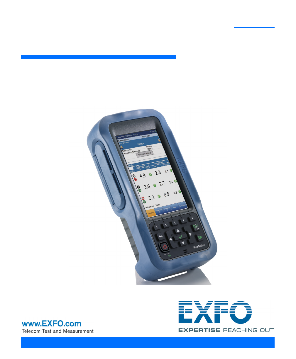
The MAX-635 is a handheld device designed for testing ADSL2+ and VDSL2
services between the service provider and the subscriber premises. The
unit also qualifies and troubleshoots copper-loop plant by using
pass/fail-driven automated functionalities.
The MaxTester 635 test set case is an aluminum enclosure with rubber over
mold, which makes it ideal for field use. Its display is a back-lit LCD
featuring 480 x 800 resolution. A membrane keypad mounted on the face
of the unit features a 14-button keypad used to operate the test set. The
following describes the features of the MAX-635.
Key Features and Benefits
Broadcom chipset
IP login
Single-ended copper testing - no remote device required
DSL testing
User-defined automatic testing
Dual Ethernet ports
Customer modem replacement
Color display with graphical analysis
Battery powered
Rugged and weatherproof handheld unit
Copper and VDSL2/ADSL2+ Multi-play Test Set 1
Page 10

Introducing the MaxTester 635
Typic a l Appli c a t ions
Typical Applications
Active and inactive pair Auto Tests
Multimeter tests
Noise tests including power influence and PSD
Frequency tests including balance, load coils, and tracing tone
Fault location tests including TDR and RFL
ADSL2+ and VDSL2 testing
Optional ADSL2+ and VDSL2 bonding support
Supports Ping, FTP, and Traceroute tests with optional support for Web
Browser, VoIP testing, and IPTV analysis
Ethernet testing for qualifying FTTx service at the customer premises
Configurable pass/fail results for automated testing
2 MAX-635
Page 11
Introducing the MaxTester 635
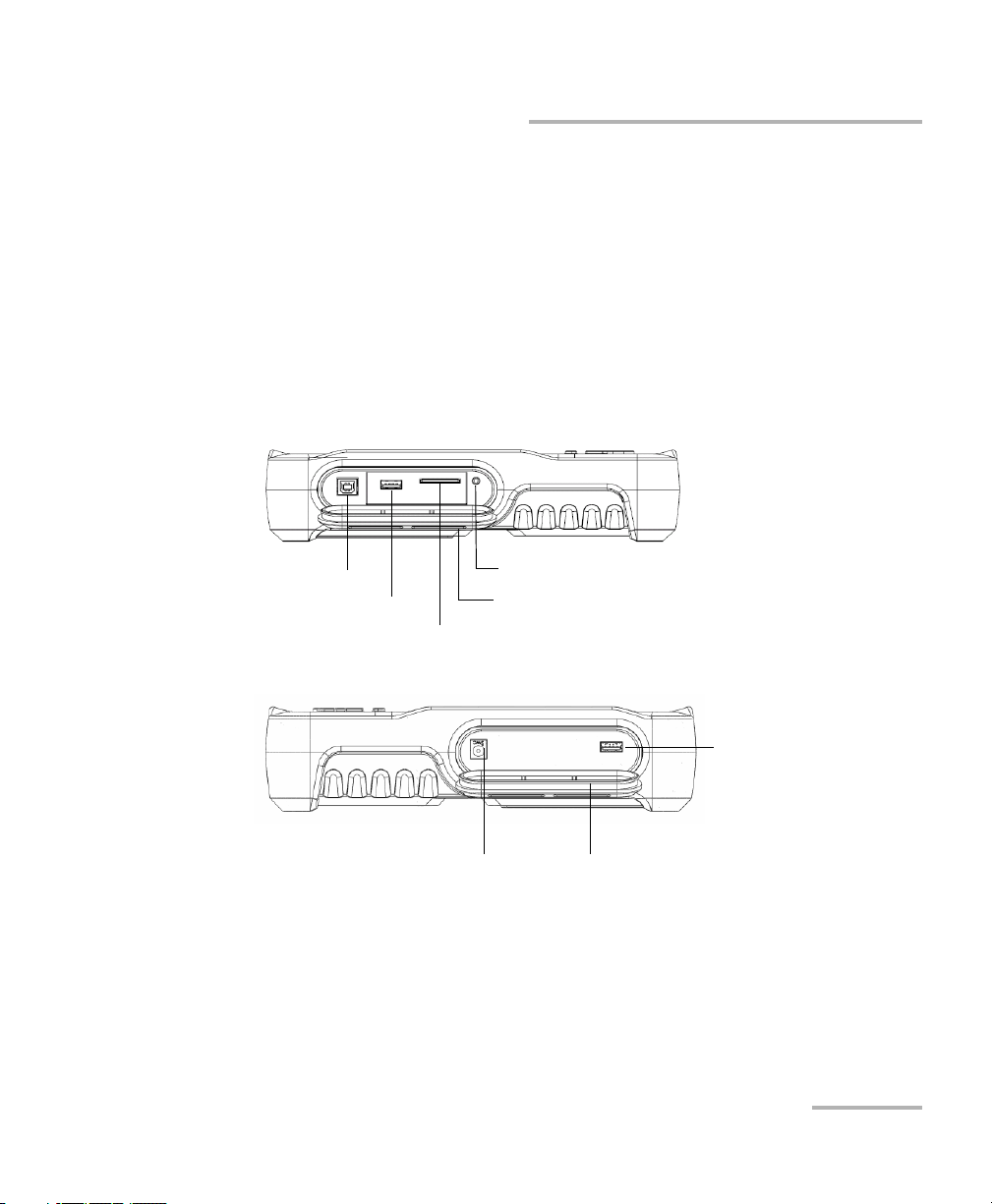
USB Host Port
USB Client Port
SD Card (not used)
Head Set Jack (2.5 mm)
Door
DC Power Door
USB Client Port
Using the MaxTester
Using the MaxTester
The MaxTester is tested IEC IP54 which means that it is not affected by dust
or water splashing against the enclosure from any direction. This
protection is only valid when both side doors are properly closed. If the
equipment is used in a manner not specified by the manufacturer, the
protection provided by the equipment may be impaired.
The MaxTester is equipped with a series of interfaces shown in the
following views:
Left
Right
Copper and VDSL2/ADSL2+ Multi-play Test Set 3
Page 12
Introducing the MaxTester 635
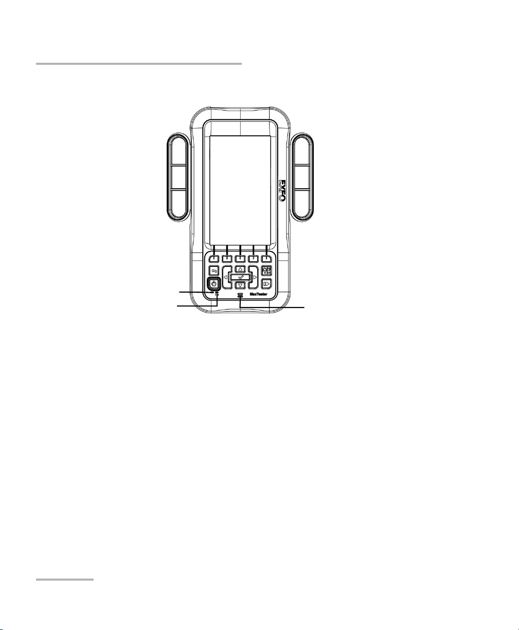
Power LED
Battery LED Speaker
Using the MaxTester
Front
4 MAX-635
Page 13
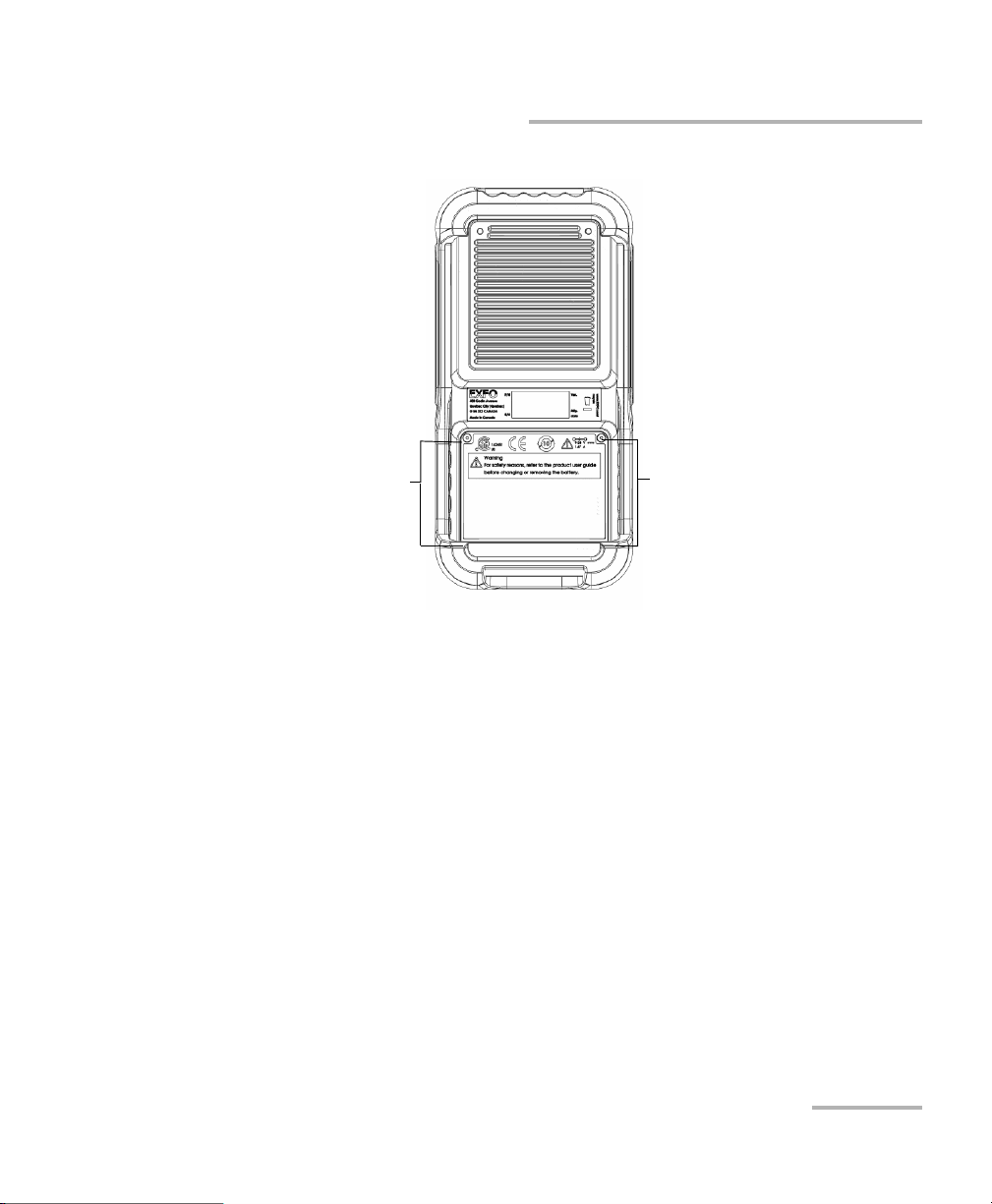
Back
Battery Door
Screws
Screws
Introducing the MaxTester 635
Using the MaxTester
Note: The MAX-635 enclosure may become warm during normal use.
Copper and VDSL2/ADSL2+ Multi-play Test Set 5
Page 14
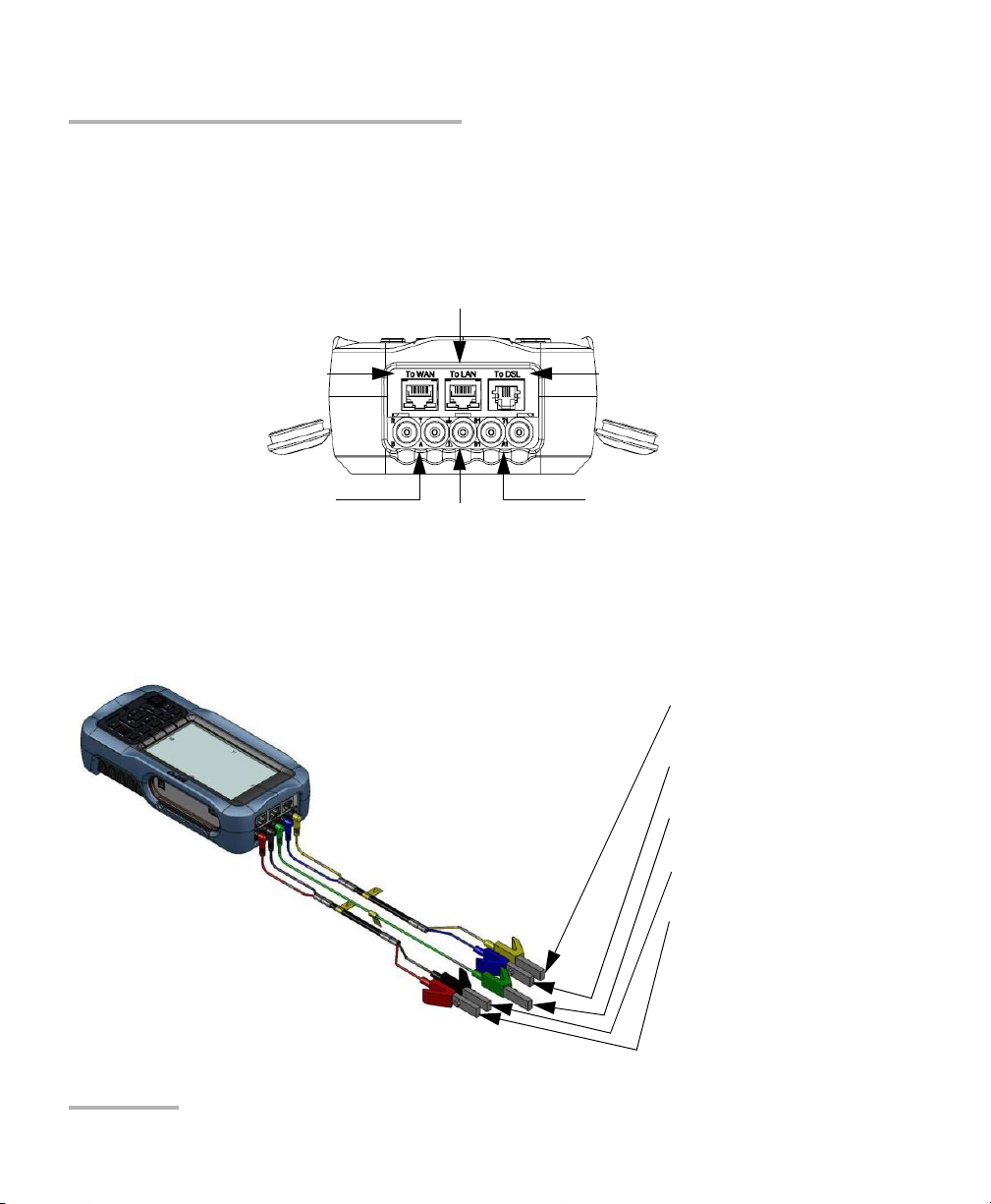
Introducing the MaxTester 635
Primary tip/A and
ring/B connectors
Secondary tip/A and
ring/B connectors
Ground
terminal
Ethernet Lan port
Ethernet
WAN port
DSL port
Secondary Tip/A wire of
phone line
Secondary Ring/B wire
of phone line
Shield of phone line
Primary Tip/A wire of
phone line
Primary Ring/B wire of
phone line
Cable Connections
Cable Connections
The graphics below show the connectors on the MaxTester device.
Note: When connecting a DSL cable to the DSL port, use the RJ-11 plug end of the
cable provided with the unit.
6 MAX-635
Page 15

Introducing the MaxTester 635
Cable Connections
WARNING
A 50 to 500 Vcc limited power source may be present on connector
R/T/R1/T1 when the unit is testing isolation resistance. Use with
caution.
WARNING
These connections are intended for the express purpose of electrical
testing of common telephone line conductors, within the ranges
specified in the Technical Specifications on page 281. The device is
not intended to be used on telephone lines having voltages greater
than 280 VAC or 400 VDC, and it is also not intended to be used on
power distribution circuits.
CAUTION
The unit is protected against damage caused by fault voltages that
may be present on lines under test. Do not connect the unit if the
maximum expected fault voltage is greater than 500 volts.
Copper and VDSL2/ADSL2+ Multi-play Test Set 7
Page 16

Introducing the MaxTester 635
Conventions
Conventions
Before using the product described in this guide, you should understand
the following conventions:
Indicates a potentially hazardous situation which, if not avoided,
could result in death or serious injury. Do not proceed unless you
understand and meet the required conditions.
Indicates a potentially hazardous situation which, if not avoided,
may result in minor or moderate injury. Do not proceed unless you
understand and meet the required conditions.
Indicates a potentially hazardous situation which, if not avoided,
may result in component damage. Do not proceed unless you
understand and meet the required conditions.
WARNING
CAUTION
CAUTION
IMPORTANT
Refers to information about this product you should not overlook.
8 MAX-635
Page 17

2 Safety Information
WARNING
The use of controls, adjustments and procedures other than those
specified herein may result in exposure to hazardous situations or
impair the protection provided by this unit.
IMPORTANT
When you see the following symbol on your unit , make sure
that you refer to the instructions provided in your user
documentation. Ensure that you understand and meet the required
conditions before using your product.
IMPORTANT
Other safety instructions relevant for your product are located
throughout this documentation, depending on the action to
perform. Make sure to read them carefully when they apply to your
situation.
Copper and VDSL2/ADSL2+ Multi-play Test Set 9
Page 18

Safety Information
Electrical Safety
Electrical Safety
The AC adapter/charger provided with this unit (18 W/9 V) is specifically
designed to work with your MaxTester.
Use the AC/DC adapter/charger indoors only.
Use only with a Class II AC/DC adapter, power limited output.
On the AC/DC adapter, replacing detachable mains supply cords
with inadequately rated cords, may result in overheating of the
cord and create a fire risk.
The adapter shall have the appropriate safety mark (e.g. UL,
CSA, TUV, CE, etc.) that is acceptable to the authorities in the
country where the equipment is to be used.
When using the MaxTester while connected to the AC/DC
adapter/charger, make sure you do not position the equipment so
that it is difficult to disconnect the adapter/charger from the
AC mains.
WARNING
CAUTION
WARNING
Use only accessories that meet EXFO specifications.
10 MAX-635
Page 19
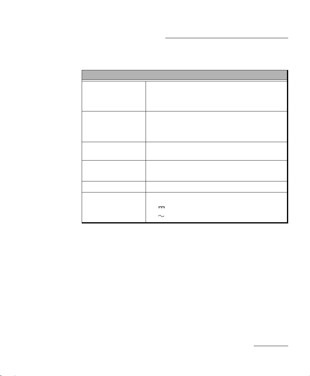
Equipment Ratings
Tem pe rat ur e
Operation
Storage
Relative humidity
unit
AC adapter
0 °C to 40 °C (32 °F to 104 °F)
–40 °C to 70 °C (–40 °F to 158 °F)
a
95 % non-condensing
0 % to 80 % non-condensing
Safety Information
Equipment Ratings
Equipment Ratings
Maximum operation
3000 m (9842 ft)
altitude
Pollution degree 2 (when plugged to AC mains)
3 (when operated from batteries)
b
c
Overvoltage category II
Input power
unit
AC adapter
a. Measured in 0 °C to 31 °C (32 °F to 87.8 °F) range, decreasing linearly to 50 % at 40 °C
(104 °F).
b. For indoor use only.
c. Equipment is normally protected against exposure to direct sunlight, precipitations and
full wind pressure.
d. Not exceeding ± 10 % of the nominal voltage.
d
9-24 V; 18 W; 1.67 A
100 - 240 V; 50/60 Hz; 0.7 A
Copper and VDSL2/ADSL2+ Multi-play Test Set 11
Page 20

Page 21

3 Getting Started with the
MaxTester
Turning the Unit On/Off
When you turn the unit on, you may use it immediately under normal
conditions. When the unit is turned off, it keeps the following parameters
in its internal memory:
Setup including application settings, phone and cable books, and test
lead characteristics.
Profiles consisting of:
Test parameters
User-defined thresholds
Note: Save the current profile before turning the unit off or else any changes are
lost. See Save Profile page 37 for more information.
Regional, LCD and energy-saving settings
Test results saved internally vs. USB
There are two ways to turn off the MaxTester
Suspend: the next time you turn your unit on, you will quickly return to
your work environment.
Shutdown: completely cuts power to the unit; the unit will perform a
complete restart routine the next time you use it. You should perform a
shutdown if you do not intend to use your unit for a few hours or more.
To turn the unit on:
Press
Home pane.
Copper and VDSL2/ADSL2+ Multi-play Test Set 13
to start. The unit initializes for a few seconds and displays the
Page 22

Getting Started with the MaxTester
Using Menus and Keypad
To enter suspend mode:
Press
for about 2 seconds. The MaxTester will stay in suspend mode for
2 hours, after which it will automatically shutdown. This prevents complete
battery discharge and ensures maximum battery performance.
To perform a shutdown:
Hold down
for about 4 seconds. The shutdown process starts.
Note: In both previous cases, if the power adapter is connected, the MaxTester
will simulate either a fake suspend or fake shutdown in order to facilitate
the charger.
Using Menus and Keypad
You can access various tools from the keypad or menu. Menu options may
differ depending on your unit configuration.
Home menu is where you can access Copper Test, DSL/IP Tests, or
System Settings.
Each test has a sub menu.
To navigate through the items, use the arrow keys.
To confirm a choice or enter a menu, press .
To cancel an action or return to the previous item or pane, press .
To return to the home pane, press .
Press once to return to the Main test menu or twice to return to the
Home pane.
Note: Pressing while a test is running will do nothing. The test can not be
running in order to return to the main menu screen.
Note: You can also select an option directly by pressing the function keys
corresponding to the on-screen buttons at the bottom of the screen.
14 MAX-635
Page 23
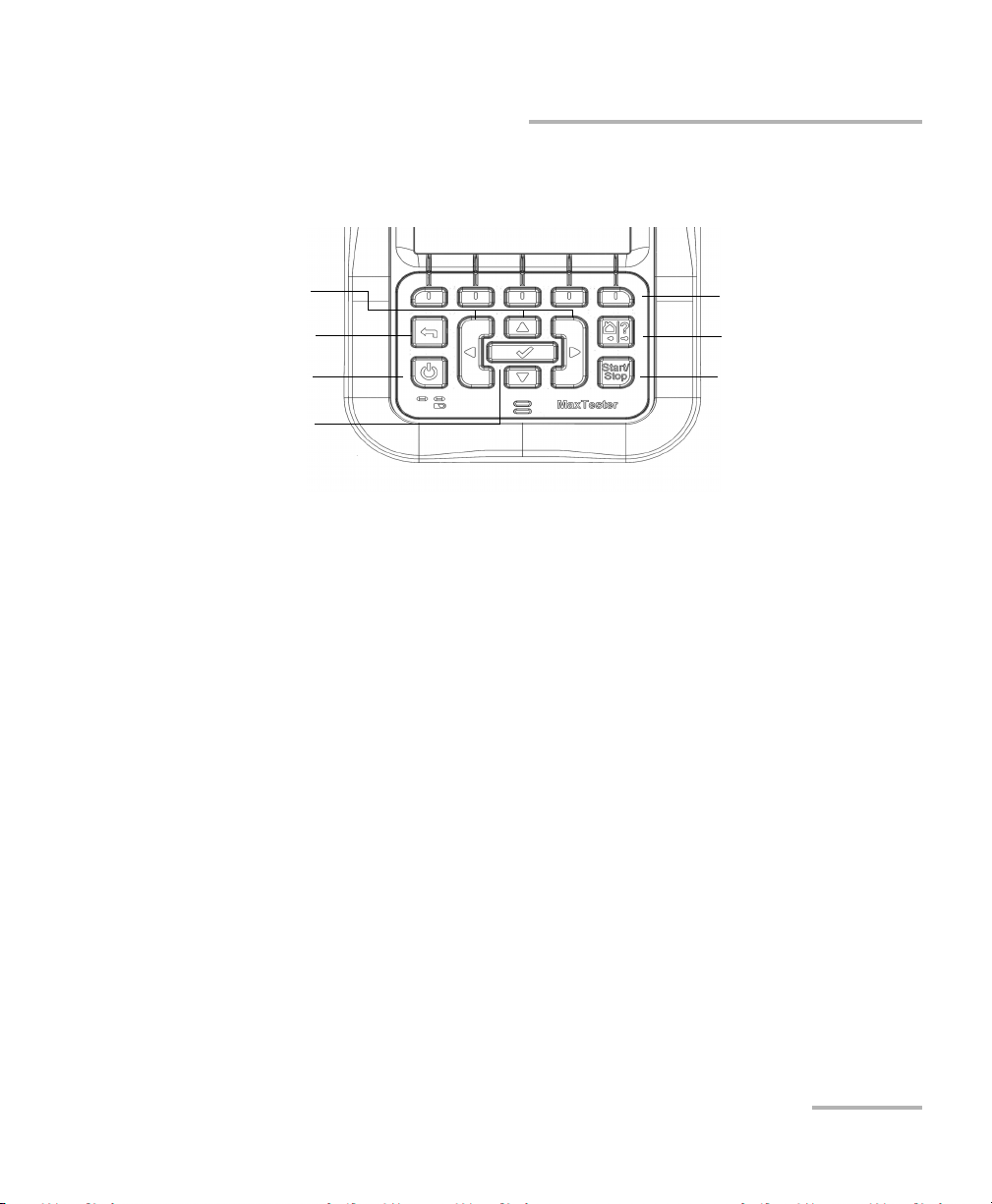
Getting Started with the MaxTester
Function keys
Home/Help
Start/Stop test
Power
Back
Arrow keys
Enter
Keypad
Power button on the lower left side of the unit is used to power the unit
on and off.
Arrow keys navigate the screen to access and modify parameters.
Function keys activate the corresponding on-screen function button.
Keypad
Home button brings you to the Home pane of the MAX-635.
Copper and VDSL2/ADSL2+ Multi-play Test Set 15
Page 24

Getting Started with the MaxTester
Using Online Help
Using Online Help
Online help is available at any time. Most test operations pause while you
view help, but will resume automatically when you exit help.
To access help about the current function at any time:
Press and hold the ? key.
16 MAX-635
Page 25
4 Setting Up the MAX-635
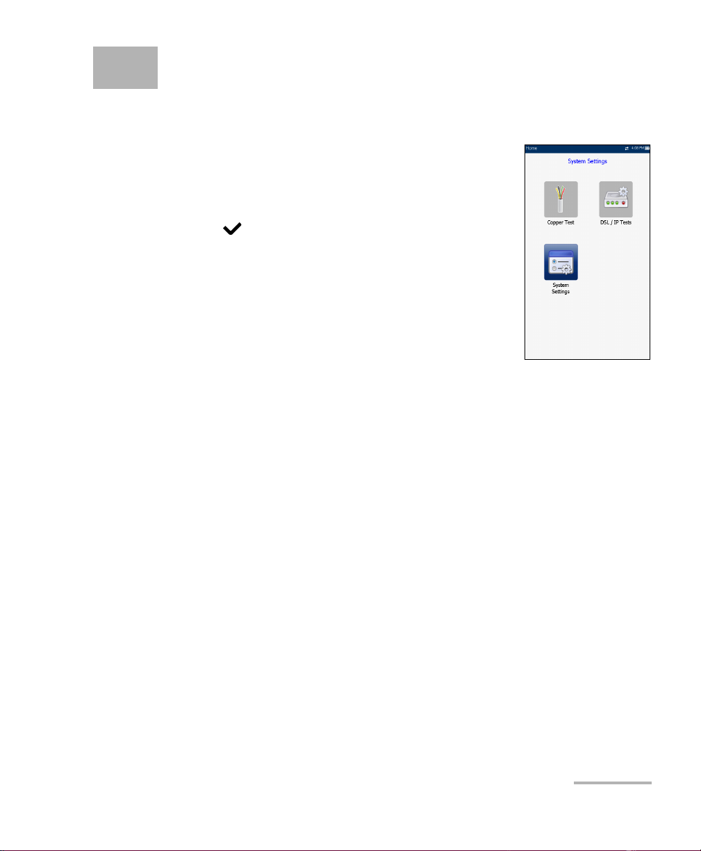
Home
Home presents the main menu page which allows
you to navigate between Copper Test, DSL/IP Tests,
and System Settings using the left/right, up/down
arrow keys on the keypad.
Press to bring up the sub-menu of the selected
icon:
Copper Test opens the Copper Main menu
displaying the copper qualification testing
applications.
DSL/IP Tests opens the DSL Main menu for
ADSL2+, VDSL2, and multi-play services testing
applications.
System Settings allow you to set the parameters of the unit and access
to Upload Setup.
Copper and VDSL2/ADSL2+ Multi-play Test Set 17
Page 26
Setting Up the MAX-635
System Settings
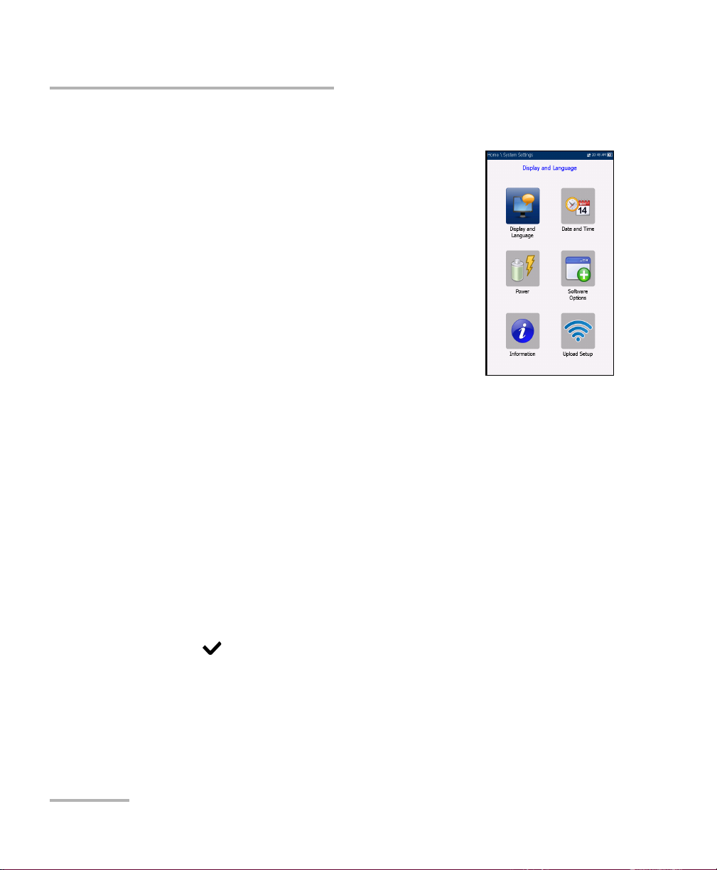
System Settings
System Settings presents a menu of items to setup
the unit.
Display and Language provides the setup for
backlight, information on the title bar, and
language choice.
Date and Time sets the date and time and format.
Power displays the BATTERY Status, Power
Schemes, and Calibration.
Software Options allow you to enable/disable
purchased feature options.
Information displays information About EXFO
and unit details pertaining to hardware/software/product info.
Upload Setup allows you to enable and select an upload method
using the following function keys:
Upload Enable
FTP Setup
Wi-Fi Setup
Ethernet Setup
To navigate between the system settings:
1. Press the up/down left/right arrow keys on the keypad to select an
icon.
2. Press to confirm your selection.
18 MAX-635
Page 27
Setting Up the MAX-635
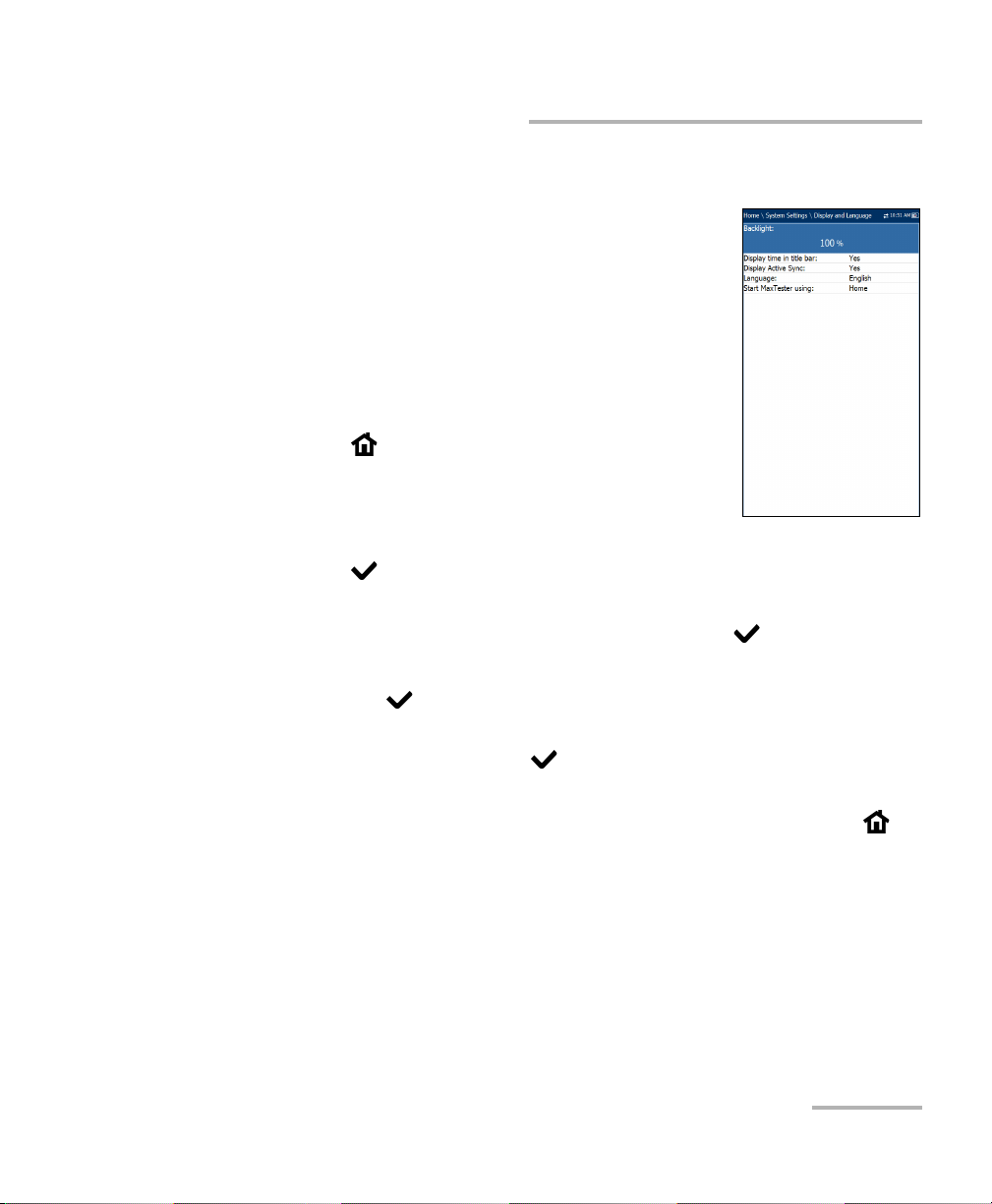
Display and Language
To fit your work environment, you may adjust the LCD
brightness, display the time and Active Sync, and
change the display language. The values are kept in
memory when you turn the unit off.
Note: The LCD Backlight consumes battery power; more
brightness, more power consumption.
To adjust the display settings:
1. From , select System Settings, and then
Display and Language.
2. Use the up/down arrow keys to select the setting
to change.
3. Press to select it.
By using the up/down arrow keys, you can switch between preset
brightness levels in the Backlight item. Press to confirm.
Display and Language
To display the time and Active Sync in the title bar, enable the item.
Press after your selection to confirm.
Use the up/down arrow keys to navigate between the available
languages, then press to select it. You will be prompted to
restart your unit.
To se t whi c h Home page the unit defaults to when pressing ,
highlight Start MaxTester using: and select from the list.
Copper and VDSL2/ADSL2+ Multi-play Test Set 19
Page 28
Setting Up the MAX-635
Date and Time
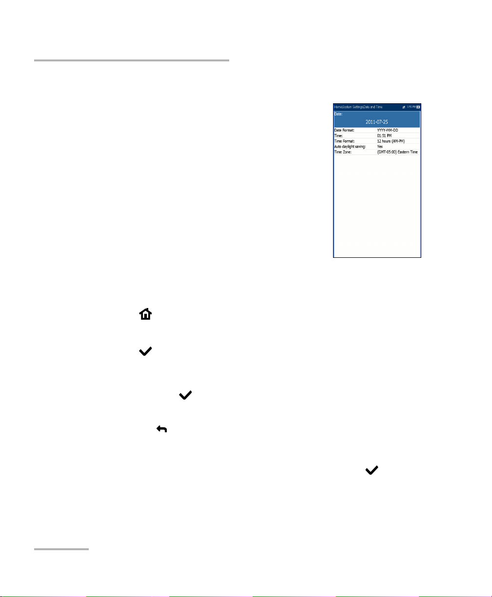
Date and Time
When saving results, the unit also saves the
corresponding Date and Time.
You can enter the date according to the following
formats:
yyyy-mm-dd
dd-mm-yyyy
mm-dd-yyyy
The time can be set according to the 12- or 24-hour
formats.
You can also modify the time zone and enable an
option so that your unit automatically adjusts the time for the daylight
saving period.
To set the date and time:
1. Press , select System Settings, and then Date and Time.
2. Use the arrows to select any of the date or time settings.
3. Press to enable the modification controls.
For the date and time, an edit screen is displayed with descriptive
function keys. Use the arrow keys to modify the number values,
then press to confirm the change and go back to the previous
screen.
Press to go back to the previous screen without saving the new
value.
For the time format, auto daylight saving and time zone values, use
the arrow keys to select the desired value, then press to
confirm the change.
20 MAX-635
Page 29
Setting Up the MAX-635
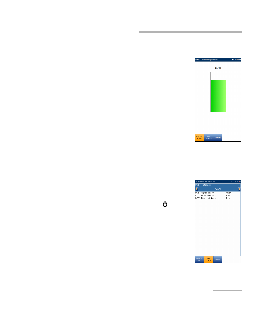
Power
Battery Status
The BATTERY Status pane indicates the current
power level for the battery.
Note: The battery level might not display after a system
upgrade but will become available again after the
next full charge.
Power Schemes
You can set your unit to automatically switch to suspend mode
independently for the battery or DC power modes. This is useful for
example if you want to save battery power but do not want to be hindered
by unwanted switches between modes when using DC power.
Pow er
Power off completely shuts down the unit’s
power.
Power suspend puts the unit in sleep mode; you
can wake up the system by pressing .
DC IN/BATTERY Idle timeout allows you to set
the time duration for the unit to idle (no keys
pressed or test being run) before turning off the
LCD.
DC IN/BATTERY suspend timeout allows you to
set the time duration for the unit to enter sleep
mode.
Copper and VDSL2/ADSL2+ Multi-play Test Set 21
Page 30
Setting Up the MAX-635
Pow er
Note: Setting the DC IN suspend timeout to the lowest value and not to Never
ensures the unit enters suspend mode while the charger is connected.
Battery charging time is quickest when the unit is in suspend mode.
Default Power Scheme settings are:
LCD backlight turns off after system idles (no keys pressed) for
10 minutes.
Unit switches to suspend mode after timeout: 10 min
To change the power scheme settings:
1. Press , select System Settings, and then Power.
2. Select the Power Schemes tab.
3. Under DC IN or BATTERY, use the arrow keys to select Idle/suspend
timeout modes. Press to view the list of available choices or use
the left/right arrow keys.
4. Select a new value, then press to confirm the choice. Repeat for
the other modes as needed.
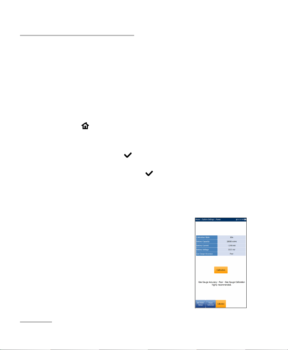
Calibration
The Calibration tab allows you to optimize the battery gas gauge accuracy.
Calibration State:
Completed displays after the calibration
procedure has been started and the DC plug
was not removed before the end was
reached.
In Progress displays when the calibration
procedure has been started but has not yet
reached the end.
22 MAX-635
Page 31

Setting Up the MAX-635
Pow er
Aborted displays when the calibration procedure has been started
but the DC plug was removed before the end.
Idle displays after the next MaxTester cold boot.
Gas Gauge Accuracy indicates the estimated battery gas gauge
accuracy.
Below 10 % accuracy error is Very Good.
Between 10 % and 20 % accuracy error is Good.
Over 20 % accuracy error is Poor and a gas gauge calibration is
needed in order to get optimal accuracy.
The following on-screen messages may appear:
Calibration Completed is displayed after the procedure has been
started and successfully completed.
Calibration In Progress is displayed when the procedure has been
started and not yet completed.
Calibration Aborted is displayed when the procedure has been
started but the DC plug was removed or a power failure occurred
before the end, or if you terminate the calibration.
To start the gas gauge calibration:
1. Select the Calibration button. Completion time is up to 20 hours
depending on the MaxTester's initial battery level and current power
consumption.
2. Make sure the DC plug always stays connected and the unit is not
turned off until completion. Failing to do so will abort the procedure
and previous calibration parameters will be kept.
Note: No other activity can be performed on the unit during calibration.
Note: Going through this calibration does not affect the MaxTester's battery
capacity.
Copper and VDSL2/ADSL2+ Multi-play Test Set 23
Page 32

Setting Up the MAX-635
Software Options
Software Options
DSL Options
This screen lists all the DSL Configured Options
which are present on the unit. Possible options are as
follow:
VDSL2MOD (Support VDSL2 test)
PING (Support Ping and IP login)
FTP (FTP Test Support)
Traceroute (Traceroute Test Support)
Browser (Web Browser Support)
IPTV (IPTV Test Support)
VOIP (VoIP Test Support)
MOS (MOS / R-Factor Scores)
24 MAX-635
Page 33

Setting Up the MAX-635
Copper Options
This screen lists all the Copper Configured Options
which are present on the unit. Possible options are as
follow:
TDR
RFL
FaultMappe r
Pair Detective
30 MHz Wideband Testing
Near End Crosstalk
Stressed Balance Test
Far End Device Test Control
Platform Options
Software Options
This screen lists all the Platform Configured Options
which are present on the unit. A possible option is:
FTP Result Upload.
Copper and VDSL2/ADSL2+ Multi-play Test Set 25
Page 34

Setting Up the MAX-635
Information
Information
About EXFO
The About tab contains contact information should
you require technical assistance.
MAX-635 Information
The Information tab displays information about the
product, software, and memory, installed on the
device. The page also identifies hardware
information.
26 MAX-635
Page 35

Upload Setup
Upload Enable
The Upload Enable function allows you to upload
your test result files.
For Copper Test use one of the following upload
methods:
Wi-Fi allows you to upload files from the
MaxTester to a Wi-Fi hotspot/router and is
available for the following results:
Copper User Auto Test - Upload/Save Result
page.
Copper User Auto Test - Read/Upload
Result/Summary page.
All tests - Copper Read/Upload Result
A Wi-Fi symbol, in the top right-hand corner of the navigation bar,
identifies whether or not a connection is present. The Wi-Fi status is
indicated as follows:
Setting Up the MAX-635
Upload Setup
Green icon indicates that the MaxTester is connected with a Wi-Fi
hotspot.
Yellow icon indicates that the Wi-Fi dongle is powered up and ok,
but that the MaxTester is not connected to any Wi-Fi hotspot.
Red icon indicates a problem with the Wi-Fi (dongle not attached,
etc.).
Copper and VDSL2/ADSL2+ Multi-play Test Set 27
Page 36

Setting Up the MAX-635
Upload Setup
Ethernet is the default upload and if selected, displays ethernet
icon in the top right-hand corner of the navigation bar. It identifies
whether or not a connection is present displaying a green or yellow
icon similar to the Wi-Fi symbol described above.
Disable Upload option disables uploading your files via Wi-Fi or
Ethernet. You can export results to a USB memory device.
For DSL tests, the In-band Upload can be set to either Enable or Disable.
To select the Upload Method:
1. Press , select System Settings, and then Upload Setup.
2. Select the Upload Enable tab.
3. Use the left/right arrow keys.
OR
4. Press to view the list of available choices.
5. Use the up/down arrow keys to make your selection and press to
confirm.
28 MAX-635
Page 37

Setting Up the MAX-635
Upload Setup
FTP Setup
The FTP Setup function allows you to configure the
file transfer information using the following
parameters:
Address Format allows you to select the FTP
server address type:
IP Address
URL
FTP Server Address allows you to set either the
IP Address or URL.
Port is a fixed numeric value for the signalling port
used to establish an IP network session.
Username/Password is your login ID and password.
Mode is either Active or Passive for the file transfer mode.
Transfer Type is set to Binary, transferring files as a binary stream of
data.
Remote Directory can be used to specify the file upload directory on
the FTP server, for example, dir1/dir2. If this field is left empty, the FTP
upload will save the result file at root directory on FTP server.
Restore Default button allows you to reset the entries to the default
settings.
Copper and VDSL2/ADSL2+ Multi-play Test Set 29
Page 38

Setting Up the MAX-635
Upload Setup
To configure the setup options:
1. Press the up/down arrows to select the desired parameter.
2. Press the left/right arrow keys to view and select the options.
OR
3. Press on a value to open a list box of options or the alphanumeric
editor screen and use the navigation keys to scroll through.
4. Press to confirm the value.
Wi-Fi Setup
The Wi-Fi Setup pages allows you to connect your
MaxTester to a Wi-Fi network.
Select a Wi-Fi Network for Upload lists the
available secure Wi-Fi networks in range and
presently connected. (Unsecured Wi-Fi networks
are not supported.) The last three networks that
were connected are also listed, whether or not
they are presently connected to the MaxTester.
Note: If you select a network from the list of previously
selected networks (last 3), the MaxTester will try to
join that network using the credentials saved for the
selected network.
Status displays a Wi-Fi symbol if the device is connected, and is
dynamically updated with the present connectivity state of the
networks.
Network Name is the Wi-Fi network name.
A third, right-hand column displays a checkmark indicating the
network selected for upload.
Forget Network button removes a previously joined network from the
list.
30 MAX-635
Page 39

Setting Up the MAX-635
Upload Setup
Select Other Network button opens a new page allowing you to
search for a specific network.
Find Networks button searches for available networks.
To connect your MaxTester to a Wi-Fi network:
1. Press the down arrow key to highlight the list box and press to get
into the list.
2. In the list, press the up/down arrows to select the desired network.
3. Press to confirm a network and open the alphanumeric editor
screen to enter your Password.
4. Press
to come out of the list.
5. Press the down and left/right arrow keys to highlight the network
buttons and press .
Copper and VDSL2/ADSL2+ Multi-play Test Set 31
Page 40

Setting Up the MAX-635
Upload Setup
Select Network
The Select Network page allows you to search for a
specific Wi-Fi network.
Network Name opens the alphanumeric editor
screen allowing you to enter the name of the
desired Wi-Fi network.
Security lists the following wireless security
protocols:
WEP (Wired Equivalent Privacy)
WPA (Wi-Fi Protected Access)
WPA2 (Wi-Fi Protected Access version 2)
Note: When using WPA encryption, some specific routers may have performance
issues with the supplied Wi-Fi dongle. In this case, please use WPA2
encryption.
Password opens the alphanumeric editor screen allowing you to enter
the desired Wi-Fi network’s password. Join function key replaces Done
on the editor screen.
Join function key allows your MaxTester to connect to the other
network and it becomes the selected/preferred upload network.
To configure the other network parameters:
1. Press the up/down arrow keys to highlight the desired parameter.
2. Press the left/right arrow keys to view and select the options.
OR
3. Press on a value to open a list box of options or the alphanumeric
editor screen and use the navigation keys to scroll through.
4. Press to confirm the value.
5. Press the Join function key to connect to the other Wi-Fi network.
32 MAX-635
Page 41

Setting Up the MAX-635
Upload Setup
Ethernet Setup
The Ethernet Setup function allows you to configure
the line and access modes, etc for an Ethernet
connection, using the following parameters:
Access Mode options are DHCP, Static, or PPPoE.
WAN Link Speed is a choice between Auto
(negotiated during the link establishment), 100 or
10 Mbit/s.
WAN Connect Mode is Full- or Half-Duplex,
when Link Speed is set to either 100 or 10 Mbit/s.
VLAN Support enables the unit to tag/untag
ethernet frames.
VLAN ID is a virtual local area network (VLAN) tag ranging from 0
through 4094. The entry is available only when VLAN Support is
Enable.
Vendor ID is the name of the unit. This entry is available only when
Access Mode is DHCP.
Local Mac Address is the internal MAC address of the unit: either
MaxTester or User Defined.
Mac Address is a specific MAC address, in a hexadecimal format, if
User Defined was selected for the previous parameter. This entry is
available only when Access Mode is DHCP or Static.
The following parameters are available only when Access Mode is PPPoE.
Login Name/Password is your user ID and password.
Obtain IP is either Dynamic where the access concentrator or
broadband remote access server assigns a temporary IP address to
the unit, or Static where you enter the IP address of the unit.
WAN Login Timeout is a numeric setup entry.
Copper and VDSL2/ADSL2+ Multi-play Test Set 33
Page 42

Setting Up the MAX-635
Upload Setup
The following parameters are available only when Access Mode is Static.
IP Address is the address for the unit that is actively connected to
your network or the internet at the time of login.
Gateway is the IP address of the default gateway.
Subnet Mask is the network address used to identify if the IP
address is within the same wide area network.
DNS1 is the address of the primary domain name server to be used
by the unit. If DNS is unavailable, enter 0.0.0.0.
DNS2 is the address of the secondary domain name server to be
used by the unit. If DNS is unavailable, enter 0.0.0.0.
Restore Default button allows you to reset the entries to the default
settings.
To configure the setup options:
1. Press the up/down arrows to select the desired parameter.
2. Press the left/right arrow keys to view and select the options.
OR
3. Press on a value to open a list box of options or the alphanumeric
editor screen and use the navigation keys to scroll through.
4. Press to confirm the value.
34 MAX-635
Page 43

5 Setting Up Copper Tests
The MaxTester is designed to test basic twisted pair quality, identify and
locate faults, and troubleshoot noise and signal issues. These
measurements offer a quick and thorough method to determine if the
cable is capable of supporting xDSL technology. In addition, it utilizes noise
measurements, longitudinal balance tests, and power spectral density tests
to assist in the installation, maintenance, and troubleshooting of copper
cables.
Copper Test Main Menu
Copper Main presents the main copper menu page
which allows you to navigate between all the copper
qualification testing applications using the up/down,
left/right arrow keys on the keypad.
Press to run a test, bring up the sub-menu, or
perform the application of the selected icon.
Copper and VDSL2/ADSL2+ Multi-play Test Set 35
Page 44

Setting Up Copper Tests
Test Configuration
Test Configuration
Before performing copper tests, you can set up the software settings and
values for the cables. The MaxTester allows you to save test parameters
and threshold settings to different profiles and reuse them as needed.
The Test Configuration menu provides the utilities to
setup test parameters. The MaxTester supports several
types of copper test applications. Test parameters and
thresholds are saved into a test configuration profile. A
Profile Default is provided with a predefined set of
parameters for all test applications.
Note: Cable parameters are not included in these profiles
but can be configured in Setup.
Select Profile lists available profiles saved in the
internal memory. The current active profile is
shown in the upper information header.
An asterisk "*" on the currently Selected Profile name indicates that
modifications have been made to this profile in the Threshold
Settings or parameters of a particular test.
At power up, settings are read from the last loaded profile.
Profile Details lists the tests for configuration:
Pair Detective
FaultMappe r
Auto Test
Multimeter
Noise Tests
Frequency Tests
TDR
36 MAX-635
Page 45

Setting Up Copper Tests
Test Configuration
Copy to USB allows you to copy all profiles found in the internal
memory to an external USB device. If the profile name already exists in
the destination folder, you will prompted to overwrite existing
profile(s).
You can overwrite each file individually by pressing the Yes button,
or overwrite all by pressing Ye s to All.
If Yes to All is not pressed, then individual files may be overwritten
by pressing Yes, or skipped by pressing No.
You can terminate the process by pressing Cancel.
Copy from USB allows you to copy all profiles found on an external
USB device to the unit.
Delete Profile allows you to delete a profile (except the default profile)
on the unit.
Profile Default resets the current test setup to the factory default
profile. If selected, a dialogue box pops up to confirm that all single
and auto test settings will revert to factory test settings.
Save Profile allows you to save changes made to selected profile. An
asterisk "*" on the Selected Profile name indicates that modifications
have been made in the Threshold Settings or parameters of a
particular test. the following function keys.
Copper and VDSL2/ADSL2+ Multi-play Test Set 37
Page 46

Setting Up Copper Tests
Test Configuration
To save a profile, use one of the following function keys:
Save allows you to save to the currently selected profile name.
Save As opens the alphanumeric editor screen allowing you to
enter a new name for the profile selected.
Don’t Save deletes the message box without saving the changes to
the currently selected profile.
To navigate between the configuration icons:
1. Press the up/down left/right arrow keys on the keypad to select an
icon.
2. Press to confirm your selection.
Select Profile
The Select Profile page lists the available profiles in
the internal memory, by Profile Name and
Modification Date.
The Selected Profile displays the current active
profile.
To select a profile:
1. Press the up/down arrow keys to highlight the
desired entry and press . The profile is loaded
and the Selected Profile is updated with the
current selection.
OR
2. Press to cancel your selection and go back to the Tes t
Configuration menu.
38 MAX-635
Page 47

Setting Up Copper Tests
Profile Details Main Menu
You can view any of your saved profiles on the
MaxTester 635 from the Profile Details menu by
selecting the desired test icon. An asterisk "*" on the
currently Selected Profile name indicates that
modifications have been made to this profile in the
Threshold Settings or parameters of a particular test.
Each test displays a sub-menu of test icons to select
and setup.
To select a test:
1. Press the up/down left/right arrow keys on the
keypad to select an icon.
2. Press to display the sub-menu test icons.
Multimeter Profile Details
The profile details Multimeter main menu allows you
to view the test threshold and parameters of the
following tests:
Test Configuration
Voltage
Current
Resistance
Resistive Balance
Isolation
Capacitance/Opens
Station Ground
Stressed Balance
Copper and VDSL2/ADSL2+ Multi-play Test Set 39
Page 48

Setting Up Copper Tests
Test Configuration
To navigate between the test profiles:
1. Press the up/down left/right arrow keys on the keypad to select an
icon.
2. Press to confirm your selection.
Noise Tests Profile Details
The profile details Noise Tests main menu allows you
to view the test threshold and parameters of the
following tests:
VF Noise
Power Influence
VF Impulse Noise
WB PSD Noise
WB Impulse Noise
NEXT
To navigate between the test profiles:
1. Press the up/down left/right arrow keys on the keypad to select an
icon.
2. Press to confirm your selection.
40 MAX-635
Page 49

Setting Up Copper Tests
Test Configuration
Frequency Tests Profile Details
The profile details Frequency Tests main menu
allows you to view the test threshold and parameters
of the following tests:
VF/AC Balance
WB Balance
WB Attenuation
TX/RX Tone
To navigate between the test profiles:
1. Press the up/down left/right arrow keys on the keypad to select an
icon.
2. Press to confirm your selection.
Auto Test Profile Details
The profile details Auto Test main menu allows you to
view the test threshold and parameters of the
following tests:
POTS Auto Test
User Auto Test
To navigate between the test profiles:
1. Press the up/down left/right arrow keys on the
keypad to select an icon.
2. Press to confirm your selection.
Copper and VDSL2/ADSL2+ Multi-play Test Set 41
Page 50

Setting Up Copper Tests
Test Configuration
Delete Profile
Delete Profile lists all profiles found on the internal
memory except the default profile, which cannot be
removed.
Selected Profile displays the profile name in use.
To delete a profile:
1. Press the up/down arrow keys to highlight the
entry to be removed and press .
2. Press the Delete function key to remove the entry
from the unit.
OR
3. Press to cancel your selection, remove any display message, and go
back without impacting any profiles.
42 MAX-635
Page 51

Setting Up Copper Tests
Setup
The Setup function allows you to set up parameters common to all tests.
To access the Setup function:
1. On the Home pane, highlight Copper Test, then press .
2. From the Copper Main page select Setup and press .
Setup presents a menu of items to setup copper tests.
Phone Book includes pages to setup and save
groups of phone numbers.
Cable Book includes pages to select, add, clone,
and delete a cable, as well as modify its details.
Application Settings include the following pages:
General, Standard, Identification, File Name,
and Buzzer. Current settings are kept in memory
and are independent of the profiles.
Factor y D efault allows you to revert the Phone
Book and/or Application Settings to the factory default values.
Setup
Test Lead Compensation overwrites the current test lead
characteristics to start resistance and capacitance compensation
based on the cable temperature of the test lead.
FED Setup is an option enabled feature that allows you to detect and
set the Teletech TS125 Remote FED (far end device) in various states.
To navigate between the setup icons:
1. Press the up/down left/right arrow keys on the keypad to select an
icon.
2. Press to confirm your selection.
Copper and VDSL2/ADSL2+ Multi-play Test Set 43
Page 52

Setting Up Copper Tests
Phone Book
Phone Book
The Phone Book menu presents a selection of
functions which allow you to manage the groups of
phone numbers relevant to performing the copper
tests. It can include a maximum of 50 groups of up to 3
individual entries each. The functions are as follow:
Select Group/Entry
Phone Book Details
Add Group
Clone Group
Delete Group
Load Phone Book
Save Phone Book
To navigate between the phone book functions:
1. Press the up/down left/right arrow keys on the keypad to select an
icon.
2. Press to confirm your selection.
44 MAX-635
Page 53

Setting Up Copper Tests
Phone Book
Select Group/Entry
The page lists entries by Group ID and Entry
Name/Type. There is 1 group of 3 factory default
entries which cannot be edited or deleted. The Phone
Book can include a maximum of 50 groups.
Group # in use displays the group number in use.
To select a group and entry:
1. Press the up/down arrow keys to highlight the
desired entry and press . The Group # in Use
is updated with the current selection.
OR
2. Press to cancel your selection and go back to the Phone Book
menu.
Phone Book Details
The Phone Book Details page allows you to view and
modify the Phone Book parameters of the currently
highlighted phone entry. As well, you can
enable/disable entries 2 and 3 in each phone group.
When creating a new phone group, only entry 1 is
enabled. Entries 2 and 3 remain disabled until entry 1
is filled in.
Group ID displays the group ID number. This is
the only parameter that cannot be modified
however you can navigate between the available
phone groups.
Entry Name is the name of the entry in the Phone Book.
Phone Number is the 10-digit numeric phone number of the entry.
Copper and VDSL2/ADSL2+ Multi-play Test Set 45
Page 54

Setting Up Copper Tests
Phone Book
Typ e displays the following list of values:
Milliwatt tone
Drop battery
Quiet line
- (for additional line types)
Enable displays either Yes or No.
Accept function key validates and updates all the parameters of the
Phone Book.
To view and modify the group details:
1. Press the up/down arrow keys to highlight the desired parameter.
2. Press the left/right arrow keys to view and select the options.
OR
3. Press on a value to open a list box of options or the alphanumeric
editor screen and use the navigation keys to scroll through.
4. Press to confirm the value.
5. Press the Accept function key to update the Phone Book with your
changes.
46 MAX-635
Page 55

Setting Up Copper Tests
Add Group
The Add Group page allows you to add a new group
entry into the Phone Book using the following
parameters for the currently highlighted Group ID.
Group ID displays the group ID number. This
parameter that cannot be modified.
Entry Name is the name of the entry in the Phone
Book.
Phone Number is the 10-digit numeric phone
number of the entry.
Typ e displays the following list of values:
Milliwatt tone
Drop battery
Quiet line
- (for additional line types)
Phone Book
Enable displays either Yes or No.
Add function key adds the new group entry to the Phone Book.
To add a new group entry:
1. Press the up/down arrow keys to highlight the desired parameter.
2. Press the left/right arrow keys to view and select the options.
OR
3. Press on a value to open a list box of options or the alphanumeric
editor screen and use the navigation keys to scroll through.
4. Press to confirm the value.
5. Press the Add function key to append the new group entry to the end
of the Phone Book. If the maximum number of Phone Book entries
has been reached, delete an entry before adding a new one.
Copper and VDSL2/ADSL2+ Multi-play Test Set 47
Page 56

Setting Up Copper Tests
Phone Book
Clone Group
The Clone Group page allows you to copy the details
of an existing entry to a new group entry in the Phone
Book. The page lists all entries by Group ID.
The list can display a maximum of 50 entries.
Group # In Use displays the Group ID number in use.
To clone a group entry:
1. Press the up/down arrow keys to highlight the
desired entry.
2. Press the Clone function key to copy the details of
the highlighted entry and append a new Group ID
to the list.
OR
3. Press to cancel your selection and go back to the Phone Book
menu.
48 MAX-635
Page 57

Setting Up Copper Tests
Phone Book
Delete Group
The Delete Group page allows you to delete a group
entry from the Phone Book. The page lists all entries
by Group ID.
Group # in Use displays the group number in use.
To delete a group entry:
1. Press the up/down arrow keys to select the entry
to be removed.
2. Press the Delete function key to remove the
selected entry from the Phone Book. If you try to
delete a cable in use, a warning message pops-up
and changes the Group # in Use to Group 1 by default.
OR
3. Press to cancel your selection, remove any display message, and go
back without impacting the Phone Book.
Copper and VDSL2/ADSL2+ Multi-play Test Set 49
Page 58

Setting Up Copper Tests
Phone Book
Load Phone Book
The Load Phone Book page allows you to import a
phone book. The page displays the file name and date
of the last phone book loaded. Only .csv files are
supported.
The Storage Location lists the load destinations:
MT internal memory
USB
File Name lists the phone book file name(s) to
load.
Load button imports the selected phone book.
You will be prompted for confirmation since this action will overwrite
the current phone book.
Cancel button removes the confirmation/warning message without
impacting the phone book.
To load a phone book:
1. Select the Storage Location using the left/right arrow keys.
OR
2. Press to display the list of options.
3. Using the up/down arrow keys, select a file name to load.
4. Press Load and confirm. The unit will remove the existing phone book
and replace it by the loaded one.
OR
5. Press Cancel to remove the message.
50 MAX-635
Page 59

Setting Up Copper Tests
Phone Book
Save Phone Book
The Save Phone Book page allows you to save or
export a phone book.
Save File allows you to enter a file name of the
current phone book to save. By default, the name
is phone_book.csv.
The Storage Location lists the save destinations:
MT internal memory
USB
Save button saves the selected file.
Note: The unit will overwrite any document with the same file name found on the
disk, without warning.
To save a phone book:
1. Accept the default file name or press to create a new one using the
edit screen.
2. Select a Storage Location.
3. Press Save.
Copper and VDSL2/ADSL2+ Multi-play Test Set 51
Page 60

Setting Up Copper Tests
Dialer Function
Dialer Function
The Dialer function provides a dial-up path from the
MAX-635 to another tester (or quiet termination or
silent switchman) through a switched circuit network.
DTMF (dual-tone multi-frequency) transmission is
enabled via the phone keypad allowing you to place
POTS calls. The dialer can be accessed from the
Copper Main pane and is also integrated into
individual test screens to give you quick access to the
manual dialer function, speed dial and last dialed lists,
without exiting the current test application.
To access the Dialer function:
1. On the Home pane use the up/down arrow keys
to highlight Copper Test, then press .
2. From the Copper Main page select Dialer and press .
Dialer
The Dialer function allows you to use the unit as a
telephone (with the built-in speaker or external
headset) and the on-screen phone keypad as a dialer
when Enter Number is invoked, whether in the test
results screens or through the separate dedicated
Dialer application. The following functions can be
accessed from this page:
Dialing Status shows the current status of the
dialed number.
Group ID displays the group ID number of the
dialed number if it was selected from the Phone
Book.
Entry ID displays the Entry Name of the dialed number if it was
selected from the Phone Book.
52 MAX-635
Page 61

Setting Up Copper Tests
Dialer Function
Enter Number displays the telephone number entered or selected
from the Recent Dialed Numbers list or Phone Book.
Recent Dialed Numbers button opens a list of recently dialed numbers
for selection.
Select From Phone Book button allows you to select a number from
the Phone Book.
Function Keys
Dial/Hang Up allows you to dial the selected or entered number,
or hang up the dialer.
Add To PhoneBook saves the entered number to the Phone Book.
Mute/Unmute Speaker changes the speaker status.
Volume adjusts the volume level.
To dial a number:
1. Use the up/down arrow keys to highlight an entry or button and
press .
2. Enter a new phone number using the on-screen keypad or select an
existing one from the lists.
3. Press the Dial function key to start the call.
Copper and VDSL2/ADSL2+ Multi-play Test Set 53
Page 62

Setting Up Copper Tests
Dialer Function
Enter Number
The Enter Number box is where you enter the phone
number you wish to dial.
To enter a phone number:
1. Press any of the buttons on the key pad by using
the navigation keys on the unit and pressing .
The selected numbers are entered in the text box.
2. Press Pause to enter a 1-second pause while
dialing. For example, pressing Pause
consecutively 3 times, creates a 3-second pause.
3. Move left or right in the text box by using
Cursor Left/Right function keys.
4. Delete a character by moving the cursor to the left of the character and
pressing the Delete function key.
5. Press Done function key when you have completed entering a phone
number.
Note: Alphabets on the key pad are for reference only. Pressing any of the buttons
will not show the alpha-character in the text box.
54 MAX-635
Page 63

Setting Up Copper Tests
Recent Dialed Numbers
The Select Number page lists a maximum of 8
recently dialed telephone numbers which you can
select to make your call.
To select a recently dialed number:
1. Use the up/down arrow keys to select an entry.
2. Press to confirm your choice. The number is
automatically entered in the Enter Number field
of the Dialer page.
Select from Phone Book
The Select Entry read-only page lists entries by Group
ID and Entry Name/Type. There is 1 group of 3 factory
default entries. The Phone Book can include a
maximum of 50 groups.
Dialer Function
Group # in Use displays the group number in use.
To select a group and entry:
Press the up/down arrow keys to highlight the desired
entry and press . The Group # in Use is updated
with the current selection and automatically entered
in the Enter Number field of the Dialer page.
Copper and VDSL2/ADSL2+ Multi-play Test Set 55
Page 64

Setting Up Copper Tests
Dialer Function
Add to Phone Book
The Add Group page allows you to add a new group
entry into the Phone Book using the following
parameters for the currently highlighted Group ID.
Group ID displays the group ID number. This
parameter that cannot be modified.
Entry Name is the name of the entry in the Phone
Book.
Phone Number is the 10-digit numeric phone
number of the entry.
Typ e displays the following list of values:
Milliwatt tone
Drop battery
Quiet line
- (for additional line types)
Enable displays either Yes or No.
Add function key adds the new group entry to the Phone Book.
To add a number to the phone book:
1. Press the up/down arrow keys to highlight the desired parameter.
2. Press the left/right arrow keys to view and select the options.
OR
3. Press on a value to open a list box of options or the alphanumeric
editor screen and use the navigation keys to scroll through.
4. Press to confirm the value.
5. Press the Add function key to append the new group entry to the end
of the Phone Book. If the maximum number of Phone Book entries
has been reached, delete an entry before adding a new one.
56 MAX-635
Page 65

Setting Up Copper Tests
Cable Book
The Cable Book menu allows you to select, add,
clone, and delete a cable, as well as modify its details,
such as:
Select Cable
Cable Details
Add Cable
Clone Cable
Delete Cable
To navigate between the cable book functions:
1. Press the up/down left/right arrow keys on the keypad to select an
icon.
2. Press to confirm your selection.
Select Cable
Cable Book
The Select Cable page lists entries by Cable ID and
Cable Name. There are a minimum of 10 factory
default cable entries which cannot be edited or
deleted. The list can display a maximum of 25 entries.
Cable # in Use displays the Cable ID number in use.
To select a cable in use:
1. Press the up/down arrow keys to highlight the
desired entry and press . The Cable # in Use is
updated with the current selection.
OR
2. Press to cancel your selection and go back to the Cable Book
menu.
Copper and VDSL2/ADSL2+ Multi-play Test Set 57
Page 66

Setting Up Copper Tests
Cable Book
Cable Details
The Cable Details page allows you to view the cable
parameter details of the currently highlighted cable
entry.
Cable ID displays the cable ID number.
Cable Name is the name of the cable in the Cable
Book.
Cable Gauge is the gauge system for measuring
wire sizes in AWG (American Wire Gauge) units
or mm (metric wire size).
Cable Fill is the type of material the cable is filled
with: Aircore, Jelly, Pulp, 5 PR, or 2 PR.
Capacitance T-R/A-B specifies a value for the capacitance per length
constant.
Capacitance T/R to GND/A/B to E specifies a value for the capacitance
per length to ground constant.
Resistance specifies a value for the resistance constant of the cable.
Attenuation @ 300 kHz specifies a value for the reduction in signal
strength or insertion loss of the cable.
VOP is the velocity of propagation for the cable as a ratio of the speed
of light.
Tem pe ra tu re specifies the temperature of reference at which all cable
parameters have been measured, in either F (Fahrenheit) or C
(Celsius) units. The measurement units are updated based on the
Tem pe ra tu re settings in Setup/Application Settings/Standard.
58 MAX-635
Page 67

Setting Up Copper Tests
Cable Book
To view and modify the cable details:
1. Press the up/down arrow keys to highlight the desired parameter.
2. Press the left/right arrow keys to view and select the options.
OR
3. Press on a value to open a list box of options or the alphanumeric
editor screen and use the navigation keys to scroll through.
4. Press to confirm the value.
5. Press the Accept function key to update the cable details with your
changes.
Add Cable
The Add Cable page allows you to add a new cable
entry into the Cable Book using the following
parameters for the currently highlighted Cable ID.
Cable ID displays the cable ID number. This
parameter that cannot be modified.
Cable Name is the name of the cable in the Cable
Book.
Cable Gauge is the gauge system for measuring
wire sizes in AWG (American Wire Gauge) units
or mm (metric wire size).
Cable Fill allows you to select the type of material the cable can be
filled with: Aircore, Jelly, Pulp 5, PR, or 2 PR.
Capacitance T-R/A-B allows you to specify a value for the capacitance
per length constant.
Capacitance T/R to GND/A/B to E allows you to specify a value for the
capacitance per length to ground constant.
Resistance allows you specify a value for the resistance constant of the
cable.
Copper and VDSL2/ADSL2+ Multi-play Test Set 59
Page 68

Setting Up Copper Tests
Cable Book
Attenuation @ 300 kHz allows you to specify a value for the reduction
in signal strength or insertion loss of the cable.
VOP allows you to set the velocity of propagation for the cable as a
ratio of the speed of light.
Tem pe ra tu re specifies the temperature of reference at which all cable
parameters have been measured.
Add function key adds the new cable entry to the Cable Book.
To add a new cable entry:
1. Press the up/down arrow keys to highlight the desired parameter.
2. Press the left/right arrow keys to view and select the options.
OR
3. Press on a value to open a list box of options or the alphanumeric
editor screen and use the navigation keys to scroll through.
4. Press to confirm the value.
5. Press the Add function key to append the new cable entry to the end of
the Cable Book. If the maximum number of Cable Book entries has
been reached, delete an entry before adding a new one.
60 MAX-635
Page 69

Setting Up Copper Tests
Cable Book
Clone Cable
The Clone Cable page allows you to copy the cable
details of an existing entry to a new cable entry in the
Cable Book. The page lists all entries by Cable ID and
Cable Name.
The list can display a maximum of 25 entries of which
10 are factory default.
Cable # In Use displays the Cable ID number in use.
To clone a cable entry:
1. Press the up/down arrow keys to highlight the
desired entry.
2. Press the Clone function key to copy the details of the highlighted entry
and append a new Cable ID to the list.
OR
3. Press to cancel your selection and go back to the Cable Book
menu.
Copper and VDSL2/ADSL2+ Multi-play Test Set 61
Page 70

Setting Up Copper Tests
Cable Book
Delete Cable
The Delete Cable page allows you to delete a cable
entry from the Cable Book. The page lists all entries,
excluding the 10 factory default cable entries, by
Cable ID and Cable Name.
Cable # In Use displays the Cable ID number in use.
To delete a cable entry:
1. Press the up/down arrow keys to highlight the
entry to be removed and press .
2. Press the Delete function key to remove the entry
from the Cable Book. If you try to delete a cable in
use, a warning message pops-up and changes the Cable # in Use to
cable #1 by default.
OR
3. Press to cancel your selection, remove any display message, and go
back without impacting the Cable Book.
62 MAX-635
Page 71

Setting Up Copper Tests
Application Settings
Application Settings
Before executing the copper tests, set up the software settings and values
for the cables. The MAX-635 allows you to save standard parameter settings
to different profiles and reuse them as needed.
To access Application Settings:
From the Home pane, select Copper Test, then Setup, and
Application Settings.
The following parameters are available to configure:
General
The General tab allows you to configure the unit with
specific measurement values and graph viewing
settings.
Each parameter is described below:
Cable Temperature specifies the temperature of
the cable under test in either F (Fahrenheit) or C
(Celsius) units.
Capacitance Measurement is either 3Terminal
or 2Terminal. The latter method measures the
capacitance across the 2 terminals specified
(either T-R, T-G, R-G or A-B, A-E, B-E), whereas the
3Terminal method measures the capacitance across the 2 terminals
specified, and shorts the remaining (or unspecified) terminal to G/E.
Note: In order to correctly determine cable length by using the Capacitance
Measurement, the Cable Book must contain both 3/2 Terminal values.
Note: The accuracy of the 2 Terminal Capacitance Measurement is impacted by
the use of the FED, and the 3 Terminal method is recommended to be used
instead.
Copper and VDSL2/ADSL2+ Multi-play Test Set 63
Page 72

Setting Up Copper Tests
Application Settings
Test Startup Mode lists the test startup type:
Auto (default) automatically starts a test when you select the
respective icon from the test sub-menu pane and press .
Manual requires that you press Start/Stop on the MaxTester keypad
to start a test.
Report Format is HTML, MHTML, or XML as the generated report
format.
Prompt To Save Results allows you to Enable/Disable popup
confirmation messages before leaving a test and not saving results.
Result File Storage Location allows you to select where to save your
results: to a USB or the internal memory of the MaxTester.
Landscape Mode Settings:
Default Graph Mode sets the default graph viewing mode to either
Portrait or Landscape.
Screen Rotation sets your preferred default rotation of the unit for
viewing graphs in Landscape mode. Select either Right to rotate
the MaxTester 90 degrees clockwise so that the keypad is on the
left-hand side, or Left to rotate the unit 90 degrees
counter-clockwise so that the keypad is on the right-hand side.
To select the parameter values:
1. Press the up/down arrow keys to highlight the desired parameter.
2. Press the left/right arrow keys to view and select the options.
OR
3. Press on a value to open a list box of options or the alphanumeric
editor screen and use the navigation keys to scroll through.
4. Press to confirm the value.
64 MAX-635
Page 73

Standard
The Standard tab allows you to set unit parameter
values composed of the following:
Standard Selection
Standard allows you to specify if the copper tests
should conform to the ITU (International
Telecommunications) or ANSI (American National
Standards Institute) standard.
Note: Selecting the Standard resets the default
Measurement Units, Label Customization, and Te st
Parameters Preset for the page.
Measurement Units
Distance lists the measurement units for distance in feet or meters.
Tem pe ra tu re lists the measurement units for temperature in
F (Fahrenheit) or C (Celsius).
Setting Up Copper Tests
Application Settings
Level lists the units of power level in dBm or dBRN.
Capacitance lists the units of capacitance for Tip and Ring in
(nF/km or nF/mi).
Resistance lists the units for resistance in (Ω/km or Ω/mi).
Attenuation lists the units for the reduction in signal strength or
insertion loss of the cable, in (dB/km or dB/mi).
Power Spectral Density (PSD) lists the units to measure the noise
energy at a point in a noise spectrum. Units are dependent on the
previously selected Level.
Copper and VDSL2/ADSL2+ Multi-play Test Set 65
Page 74

Setting Up Copper Tests
Application Settings
Label Customization
Connection lists the type of cable connection: T-R-G or A-B-E.
Test Parameters Preset
Power Line Frequency lists the frequency value of the power line.
Termination Impedance lists the values for the impedance of the
dummy load connected to the line.
When FED is Enabled on the FED Setup page, the termination
resistance of the FED is the same as the MaxTester except when
Standard is set to ITU, the termination resistance of the FED will
remain at 120
Noise Filter lists the type of noise filters to use.
To select the parameter values:
1. Press the up/down arrow keys to highlight the desired parameter.
2. Press the left/right arrow keys to view and select the options.
OR
Ω since it does not support 135 ohm termination.
3. Press on a value to open a list box of options.
4. Press to confirm the value.
66 MAX-635
Page 75

Setting Up Copper Tests
Identification
The Identification tab allows you to preset values to
identify each single and auto test result file when
saving them. The parameters are as follow:
User Name/User ID allow you to enter up to 25
alphanumeric characters, in each field.
Test F r om/To list the following values: DSLAM,
NID, CPE, CROSSBOX, FRAME - up to 20 entries
each, including user defined values.
Test F r om/To List Setup buttons open separate
list management pages.
Application Settings
Copper and VDSL2/ADSL2+ Multi-play Test Set 67
Page 76

Setting Up Copper Tests
Application Settings
To select the parameter values:
1. Press the up/down arrow keys to highlight the desired parameter.
2. Press the left/right arrow keys to view and select the options.
OR
3. Press on a value to open a list box of options or the alphanumeric
editor screen and use the navigation keys to scroll through.
4. Press to confirm the value.
Test List Setup
The Test From List Setup and Test To L i st Se t up
pages allow you to manage the entries of the list.
However, there are 5 entries by default which cannot
be edited or deleted. These are DSLAM, NID, CPE,
CROSSBOX, and FRAME. When any of these are
selected, the Delete and Accept buttons are disabled.
A maximum of 20 different entries can be added.
To manage the list:
1. Press the left/right arrow keys to select the
Previous/Next Entry buttons and press to
select the previous/next entry.
2. Press Page Up/Down function keys to see entries on the previous or
next pages. These keys are disabled if no other pages exist.
3. Press Add function key to add an entry just below the selected entry in
the list.
4. To edit an entry, press the up/down arrow keys to highlight the selected
test. Press Accept function key to confirm the changes. If you press
Previous/Next Entry buttons before the Accept function key, the
edited value will be lost.
5. Press Delete function key to delete any entry you have added.
68 MAX-635
Page 77

Setting Up Copper Tests
Application Settings
File Name
The File Name tab sets up the standard configuration
for automatically naming a result file. You can only
Enable/Disable the entries. All enabled entries are
considered for file name generation.
File Name Preview displays a preview of the file
name. The actual values of the enabled entries
are not shown.
Date and Time value format depends on the
format selected in System Settings. This entry
cannot be disabled.
Separator allows you to choose a value to
separate the enabled entries in the file name, e.g.: Space ( ), Dash (-),
Underscore (_).
To select an entry and choose a value:
1. Press the up/down arrow keys to highlight the desired entry.
2. Press the left/right arrow keys to view and select the options.
OR
3. Press on a value to open a list box of options.
4. Press the up/down arrow keys to select the option and press to
confirm your selection.
Copper and VDSL2/ADSL2+ Multi-play Test Set 69
Page 78

Setting Up Copper Tests
Application Settings
Change Order
Change Order page allows you to change the order of
the entries in the file name.
To change the order:
1. Press to get into the list.
2. Use the up/down arrow keys to select the desired
entry.
3. Press to come out of the list.
4. Press the up or down arrow key to activate the
Up/Down buttons.
5. Using the left/right arrow keys, select Up/Down and press to move
the entry up/down the list.
6. Press to go back to the File Name tab. The File Name Preview will
be updated with your changes.
70 MAX-635
Page 79

Setting Up Copper Tests
Application Settings
Buzzer
The Buzzer tab allows you to configure values for the
buzzer settings. However, due to the risk of electrical
shocks, the MaxTester detects high voltages on any
pair of leads without user intervention.
Buzzer Threshold Voltage allows you to
configure the hazardous voltage level from 70 to
150 volts.
Hush Time allows you to configure the hush
timeout from 1 to 15 minutes.
Hush Buzzer button mutes the sounding buzzer.
Note: Upon raising the hazardous voltage flag, the MaxTester opens the relays
and you will have to press Start/Stop on the keypad to re initialize the unit.
In case the voltage is still too high, the MaxTester will open the relays once
again preventing any damage to the equipment. If not, the test will start
normally.
To set the buzzer settings:
1. Use the up/down arrow keys to select the desired parameter.
2. Press on an entry to open the alphanumeric editor screen and use
the navigation keys to scroll through.
3. Press to confirm each value.
Copper and VDSL2/ADSL2+ Multi-play Test Set 71
Page 80

Setting Up Copper Tests
Test Lead Compensation
Test Lead Compensation
Test lead compensation is required for some of the
copper tests so as not to affect data accuracy, since
test lead characteristics have some impact on copper
test results (mainly resistance, capacitance, and TDR
tests). Test lead characteristics vary with respect to
cable temperature.Refer to Cable Connections on
page 6 on how to connect the leads before starting
compensation.
The Test L ea d Comp e nsati o n routine allows you to
perform resistance and capacitance compensation.
The page displays the Pass/Fail status of the last
compensation done.
Note: Always perform a test lead compensation if the test leads have recently
been removed or replaced.
Date and Time identifies when the last compensation was done or
application installation time.
Start Compensation button allows you to start the Tes t Le ad
Compensation by overwriting the current test lead characteristics.
To perform a test lead compensation:
1. Connect the cables to the unit, leave all test leads open, and press
to start compensation.
2. Follow the on-screen dialogue boxes for next steps.
72 MAX-635
Page 81

Setting Up Copper Tests
FED Setup
FED Setup is an option enabled feature that implements Teletech TS125
Remote FED (far end device) detection and allows you to predetermine
and place the FED in one of the following states:
Pass Through/Exchange Connect
Open
T-R-G/A-B-E Shorted
By connecting the T-R-G/A-B-E of a customer’s pair (CPE) to the customer
side of the FED, control signals are sent to the FED by the MaxTester in
order to open/short (or pass through to the CO/Exchange) the T-R-G/A-B-E
connections.
Set the T-R-G/A-B-E connections as follows for each FED state:
1. Fo r Pass Through/Exchange Connect, set the FED so that the T-R/A-B
wires connected to the FED (on the customer side) pass directly
through the FED to the CO/Exchange side.
FED Setup
Copper and VDSL2/ADSL2+ Multi-play Test Set 73
Page 82

Setting Up Copper Tests
FED Setup
2. Fo r Open, set the FED so that the T-R/A-B wires connected to the
customer side of the FED are open circuited.
3. Fo r T-R-G/A-B-E Shorted, set the FED so that T-R-G/A-B-E are all short
circuited (connected to each other) at the customer side of the FED.
Note: P. U . T., in the above diagrams, refers to the Pair Under Test.
Remote is the FED, and Controller is the MaxTester.
74 MAX-635
Page 83

Setting Up Copper Tests
FED Setup
The FED Setup tab displays the following parameters:
FED sets the default FED States for the following
tests to Enabled or Disabled, and is saved as part
of the profile:
Multimeter
Noise
Frequency
Other
When FED is Enabled and you start a test, the
MaxTester will warn you if the FED battery level is low. Select OK to close
the message and run the test.
FED States are displayed in the Current Test line as a numeral on the
right-hand side of the FED icon, for example . Numerals match the
following states:
0 = FED Open
1 = FED T-R/A-B Shorted
2 = FED Shorted ALL
3 = FED Pass Through/Exchange Connect
4 = FED ID Tone
5 = FED Terminated
6 = FED Crosstalk NEXT
7 = FED Transmit
8 = None
Copper and VDSL2/ADSL2+ Multi-play Test Set 75
Page 84

Setting Up Copper Tests
FED Setup
Note: For all FED States other than Pass Through/Exchange Connect, the
Dialer tab is disabled. If the dialer is already running before the test starts,
the dialer will be stopped on entry of the test with a message saying Dialer
cannot be used, hence dialer will be stopped. - similar to FaultMapper
test.
FED Factory Default button allows you to restore the factory defaults
for the following:
Single Test defaults sets the default FED state values for all the
individual tests, except Auto Test.
User Auto Test defaults sets the default FED state values for Auto
Test .
All these options sets the default FED state values for all tests.
To select the parameter values:
1. Press the up/down arrow keys to highlight the desired parameter.
2. Press the left/right arrow keys to view and select the options.
OR
3. Press on a value to open a list box of options and press the
up/down arrow keys to highlight the desired parameter.
4. Press to confirm the value.
76 MAX-635
Page 85

Setting Up Copper Tests
Multimeter
The Multimeter tab lists the default FED States set for
all multimeter tests.
Noise
The Noise tab lists the default FED States set for all
noise tests.
FED Setup
Copper and VDSL2/ADSL2+ Multi-play Test Set 77
Page 86

Setting Up Copper Tests
FED Setup
Frequency
The Frequency tab lists the default FED States set for
all frequency tests.
Other
The Other tab displays the default FED States set for
all other tests such as TDR and RFL Single/Separate
Good Pair.
78 MAX-635
Page 87

Setting Up Copper Tests
Saving Results
Saving Results
Save Result
You can save a snapshot of test results into a result file during or after a test
performed with the MAX-635. Each copper test includes a Save Result tab
to do so. The tab allows you to save your test results to an internal memory
file or export results to an HTML, MHTML, or XML report using a USB key.
Alternately, when a test is completed or stopped and
you press , Confirm Save dialogue box pops up.
Selecting Save displays the Save Result screen where
the following information can be entered:
Identification Fields
User Name/User ID display the values set up
in the Application Settings/Identification
tab. You can edit this field using the editor
screen.
Test F r om/To display the values set up in the
Application Settings/Identification tab. You
can edit this field using the choices from the list box.
Job ID allows you to create/edit a unique identifier for the task.
Customer Name is the name of the customer for which the test
was run.
Circuit ID allows you to create/edit a unique identifier for the
circuit under test.
Comments allows you to add any relevant information.
Copper and VDSL2/ADSL2+ Multi-play Test Set 79
Page 88

Setting Up Copper Tests
Saving Results
Save Result
Select Result File button displays a list of existing file names
where you can save your results.
Result File Storage Location gives you the option of storing results
either in the MaxTester internal memory or USB device. The
default selection comes from Application Settings/General tab.
Result File Name allows you to preview and edit the result file
name. The proposed file name is based on current auto-naming
parameters configured in Setup/Application Settings/File Name.
Save button confirms if the Result File Name is saved successfully.
Export Report
Report Format is HTML, MHTML, or XML.
You can generate and export HTML, MHTML, or XML reports from
any saved test result. Reports include:
General Information including Pass/Fail status.
Identification
Profile/Result Summary
Blank entries for your Signature and the Date.
Report File Name allows you to preview and edit the result file
name. The proposed file name is based on current auto-naming
parameters configured in Setup/Application Settings/File Name.
Export button confirms if the Report File Name is saved
successfully. If a USB device is not inserted, the following warning
dialogue box appears: USB device not present.
80 MAX-635
Page 89

Setting Up Copper Tests
Saving Results
To set parameter values and save results:
1. Press the left/right and up/down arrow keys to highlight the desired
parameter.
2. Press to display the list or select the value.
3. Press the up/down arrow key to highlight the desired value.
OR
4. Press the left arrow key to erase the existing value, and then use the
alphanumeric keypad to enter a value. To cancel the entry, press .
5. Press to accept the value.
Select Result File
Select Result File page displays a list of existing file
names where you can save your results.
To save your results to an existing File Name:
1. Use the up/down navigation keys to highlight the
desired File Name.
2. Press to confirm your selection.
Copper and VDSL2/ADSL2+ Multi-play Test Set 81
Page 90

Page 91

6 Reading Saved Copper Test
Results
Read/Upload Result
You can view or export any of your saved results with
the Copper and VDSL2/ADSL2+ Multi-play Test Set, by
highlighting the Read/Upload Result icon from the
Copper Main pane and pressing .
Results Summary
The Results Summary page allows you to select a
File Name and view the results of files previously
saved. The page lists all saved result files by test date
and time. The format of Tes t Dat e Ti me is per the
selection in System Settings. Result files can be
loaded from either the MT internal memory or a USB.
To open previously saved test results:
1. Press the left/right arrow keys to highlight the
desired Storage Location.
OR
2. Press to display the list and select the value.
3. Press the down arrow key to highlight the list box and press to
open the list.
4. In the list, press the up/down arrows to select the test results file.
5. Press to open the result file.
Copper and VDSL2/ADSL2+ Multi-play Test Set 83
Page 92

Reading Saved Copper Test Results
Read Result Menu
Read Result Menu
The Read Result menu allows you to view saved test
results with the following details:
Summary displays general information and
parameters of the test.
Result Details displays measured results for each
lead combination and cable parameters of the
test.
Profile Details displays the thresholds and setup
parameters of the test.
Phone Book displays the phone entry dialed
during the test.
FED Details displays the FED (far end device) State for the test.
The File Name of the selected saved results file is continually displayed at
the top of the page.
To navigate the results menu:
1. Press the up/down left/right arrow keys on the keypad to select an
icon.
2. Press to display the results.
84 MAX-635
Page 93

Reading Saved Copper Test Results
Read Result Menu
Summary
The results Summary page displays pass/fail status,
general and identification information, along with
comments, for the test.
General Information displays read-only
information pertaining to the test result.
Result File Name
Test D ate a nd Tim e
Test G roup
Test Identification
Test M odes
Test Lead Compensation displays read-only Date and Time and
Pass/Fail Status of the compensated resistance and capacitance
based on the cable temperature of the test lead.
Editable Identification Fields display values from the loaded file. You
can edit all fields using the editor screen or by selecting an entry from
the list box.
User Name/ID
Test Fro m/To
Job ID
Customer Name
Circuit ID
Comments
Copper and VDSL2/ADSL2+ Multi-play Test Set 85
Page 94

Reading Saved Copper Test Results
Read Result Menu
Function keys:
Save keeps any current changes with the current file name.
Save As saves the current changes under a different file name that
you can configure in the editor screen.
Don’t Save does not save any changes and closes the page.
Report allows you to load a result file to a USB device, update the
ID fields, and generate a report in either HTML, MHTML, or XML
format.
Upload (in User Auto Test only) allows you to transfer an Auto
Test result file to an FTP site or USB device via the presently
selected method (Wi-Fi or Ethernet).
To view and edit the test result information:
1. Press the up/down arrow keys to highlight and view the desired
parameter.
2. Press the left/right arrow keys to view and select the options.
OR
3. Press on an editable value to open the list box of options or the
alphanumeric editor screen. Use the navigation keys to scroll through
and select.
4. Press to confirm the value.
86 MAX-635
Page 95

Reading Saved Copper Test Results
Result Details
The Results Details page allows you to view
measured results for each lead combination and
cable parameters of the selected test.
Profile Details
The Profile Details page displays read-only test
thresholds and/or parameters information about the
setup of the selected test.
Profile Name is the file name of the selected
saved results.
Read Result Menu
Test G rou p is the overall test group of the
selected saved results file, for example
Multimeter.
Test I den t ifi c ati o n is the test type of the group, for
example Current.
Copper and VDSL2/ADSL2+ Multi-play Test Set 87
Page 96

Reading Saved Copper Test Results
Read Result Menu
Phone Book
The Phone Book page summarizes the Phone Book
details when loading a results file.
It contains information about group entries such as
group ID, name, phone numbers, and tags.
If the dialer was not used during the test, the Phone
Book icon will not appear as part of the Read Result
menu page.
FED Details
The FED Details page displays the default FED state
Value set for the test(s).
88 MAX-635
Page 97

Reading Saved Copper Test Results
Upload
The Upload page allows you to upload the saved
results of User Auto tests only to an FTP site or a USB
memory stick. Select a File Name or All files
previously saved. Files are uploaded via the selected
method (Wi-Fi or Ethernet) as shown by the
corresponding icon in the top right-hand corner of the
navigation bar.
Upload Location is either FTP or USB.
Select Files is either None which removes all
check marks allowing you to select one or more
files, or All.
Uploaded status column displays a successful, failed, or no upload for
each file.
Upload button transfers the selected files to the designated location.
Delete button removes selected XML files from the internal memory.
Upload
To upload previously saved User Auto Test results:
1. Press the left/right arrow keys to highlight the desired Upload
Location.
OR
2. Press to display the list and select the value.
3. Press the down arrow key and select either None or All files.
4. If None, press the down arrow key to highlight the list box and press
to open the list.
5. In the list, press the up/down arrows to select the desired files.
6. Press
to come out of the list.
7. Press the down arrow key to highlight either Upload or Delete and
press .
Copper and VDSL2/ADSL2+ Multi-play Test Set 89
Page 98

Reading Saved Copper Test Results
Export
Export
The Export page allows you to select a File Name or
All files previously saved and export the results in a
selected Report Format.
Storage Location gives you the option of
exporting your results to either the MT internal
memory or USB device.
Select Files is either None or All. None removes
all check marks allowing you to select one or
more files, or All.
Report Format is HTML, MHTML, or XML.
Export button transfers the selected file(s) to the internal memory or
USB device in the selected report format.
To export previously saved test results:
1. Press the left/right arrow keys to highlight the desired Storage
Location.
OR
2. Press to display the list and select the value.
3. Press the down arrow key and select either None or All files.
4. If None, press the down arrow key to highlight the list box and press
to open the list.
5. In the list, press the up/down arrows to select the desired files.
6. Press
to come out of the list.
7. Press the down arrow key to highlight the Report Format.
90 MAX-635
Page 99

Reading Saved Copper Test Results
8. Press the left/right arrow keys to select the desired format
OR
9. Press to display the list and select the value.
10. Press the down arrow key to press the Export button.
Export
Copper and VDSL2/ADSL2+ Multi-play Test Set 91
Page 100

 Loading...