


PC 300
Technolo
g
y
M
ade
E
a
s
y
.
.
.
Instruction Manual
PC 300
Waterproof Hand-held pH/Conductivity/TDS/Temperature Meter
35631-00
68X248908
Rev3 01/04


Preface
This manual serves to explain the use of the Waterproof PC 300 hand-held meter. It functions in
two ways, firstly as a step by step guide to help you to operate the meter. Secondly, it serves as a
handy reference guide. It is written to cover as many anticipated applications of the Waterproof PC
300 hand-held meter as possible. If there are doubts in the use of the PC 300, please do not
hesitate to contact the nearest Eutech Instruments/ Oakton Instruments Authorized Distributor.
Eutech Instruments/ Oakton Instruments cannot accept any responsibility for damage or
malfunction to the meter caused by improper use of the instrument.
The information presented in this manual is subject to change without notice as improvements are
made, and does not represent a commitment on the part of Eutech Instruments Pte Ltd/ Oakton
Instruments.
Copyright © Feb 2000 All rights reserved.
Eutech Instruments Pte Ltd/ Oakton Instruments
Rev3 01/04

TABLE OF CONTENTS
1 INTRODUCTION 1
2 DISPLAY AND KEYPAD FUNCTIONS 2
2.1 Display 2
2.2 Keypad 3
3 PREPARATION 4
3.1 Inserting the Batteries 4
3.2 Probe Information 5
4 CALIBRATION 7
4.1 Important Information on Meter Calibration 7
4.2 Preparing the Meter for Calibration 8
4.3 pH Calibration 8
4.4 Conductivity Calibration 11
4.5 TDS Calibration 14
4.6 Calibration with Conductivity Standard and TDS factor 15
4.7 Temperature Calibration 16
5 MEASUREMENT 18
5.1 Taking pH Measurements 18
5.2 Taking Conductivity or TDS Measurement 22
6 HOLD FUNCTION 28
7 ADVANCED SETUP FUNCTIONS 29
7.1 Advanced SETUP Mode Overview 31
7.2 P1.0: Viewing previous pH calibration data 34
7.3 P2.0: Viewing pH electrode data 35
7.4 P3.0: pH Measurement configuration 36
7.5 P4.0: Resetting to factory default settin g s (pH ) 40
7.6 P5.0: Viewing Previous Conductivity Calibration data 41
7.7 P6.0: Viewing Conductivity Probe Data 42
7.8 P7.0: Conductivity or TDS Measurement Configuration 43
7.9 P8.0 Temperature 47
8 PROBE CARE AND MAINTENANCE 50
8.1 pH Electrode care 50
8.2 Conductivity Electrode 52
9 TROUBLE SHOOTING GUIDE 53
10 ERROR MESSAGES 54
11 SPECIFICATIONS 55
12 ACCESSORIES 56
13 ADDENDUM 1: CONDUCTIVITY TO TDS CONVERSION FACTORS 58
14 ADDENDUM 2: CALCULATING TDS CONVERSION FACTORS 59
15 ADDENDUM 3: CALCULATING TEMPERATURE COEFFICIENTS 60
16 ADDENDUM 4: METER FACTORY DEFAULT SETTINGS 62
17 ADDENDUM 5: SELECTING USA OR NIST BUFFER SET IN P3.3 63
18 WARRANTY 64
19 RETURN OF ITEMS 65
Instruction Manual PC 300
1
1 INTRODUCTION
Thank you for selecting the PC300 waterproof portable meter. This meter is a microprocessor-
based instrument that is designed to be handy capable of allowing one-hand operation. It is
capable of measuring pH, Conductivity, TDS and Temperature. It is completely
WATERPROOF --- and it FLOATS!
This meter has many user-friendly features ---- all of which are completely access ible through
the water-resistant membrane keypad. Your meter includes a conductivity electrode (cell
constant K = 1.0) with built-in temperature sensor (Order Code: EC-CONSEN91W/ 35608-50),
pH electrode (EC-FE72522-01B/ 35641-51) and batteries. Please read this manual thoroughl y
before operating your meter.
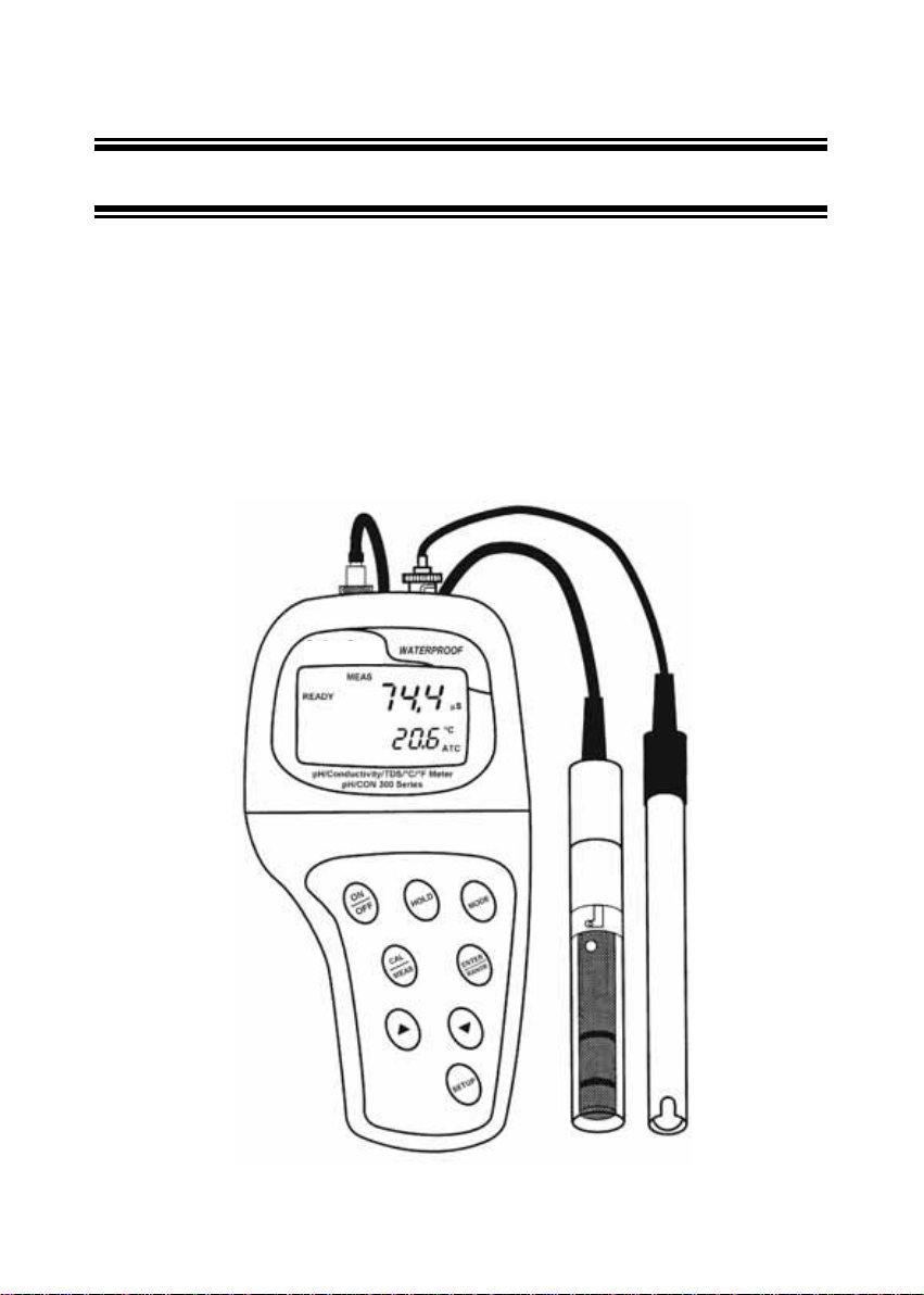
Figure 1: PC 300 meter

Instruction Manual PC 300
2
2 DISPLAY AND KEYPAD FUNCTIONS
2.1 Display
The LCD has a primary and secondary display.
• The primary display shows the measured pH, conductivity or TDS.
• The secondary display shows the measured temperature.
The display also shows error messages, keypad functions and program functions.
See Figure 2.
Figure 2: Full LCD Screen
1. SETup mode indicator 8. micro-siemens indicator 15. Low battery indicator
2. MEASurement mode
indicator
9. parts per thousand indicator 16. Probe indicator
3. CALibration indicator 10. parts per million indicator 17. Calibration solution
indicator
4. mV indicator 11. Temperature indicator 18. Cell constant indicator
5. % indicator 12. pH indicator 19. ON / OFF indicator
6. pH measurement indicator 13. Automa tic Temperature
Compensation indicator
20. HOLD indicator
7. milli-Siemens indicator 14. ERRor indicator 21. READY indicator

Instruction Manual PC 300
3
2.2 Keypad
The large membrane keypad makes the instrument easy to use. Each button, when pressed,
has a corresponding graphic indicator on the LCD. See Figure 1. Some buttons have several
functions depending on its mode of operation.
Key Function
ON/OFF Powers on and shuts off the meter. When you switch on the meter, the meter starts up
in the mode that you last switched off from. For example, if you shut the meter off in
conductivity measurement mode, the meter will be in conductivity measurement mode
when you switch the meter on.
HOLD Freezes the measured reading. To activate, press HOLD while in measurement mode.
To release, press HOLD again.
MODE Selects the measurement parameter. Press MODE to toggle between pH or TDS or
conductivity measurement mode.
CAL/MEAS Toggles between Calibration and Measurement mode.
1. If you are in pH measurement mode, press CAL/MEAS to enter pH calibration
mode.
2. If you are in conductivity measurement mode, press CAL/MEAS to enter
conductivity calibration mode.
3. If you are in TDS measurement mode, press CAL/MEAS to enter TDS
measurement calibration mode.
While in SETUP sub-menu, pressing CAL/MEAS once takes you out to the SETUP
main menu and pressing CAL/MEAS second time takes you directly into the
measurement mode.
ENTER /
RANGE
ENTER function: Press to confirm values in Calibration mode and to confirm selections
in SETUP mode.
RANGE function (for conductivity &TDS measurements only): Press to enter manual
ranging function. The MEAS indicator blinks while in manual ranging function.
/ In Calibration mode:
During conductivity and TDS calibration, press to scroll through calibration values.
In SETUP mode:
Press to scroll through the setup subgroup programs.
SETUP Takes you into the SETUP mode. This mode lets you customize meter preference and
defaults, view calibration, electrode offset data, adjust for temperature coefficient and
normalization temperature.

Instruction Manual PC 300
4
3 PREPARATION
3.1 Inse rting the Batteries
Four AAA batteries are included with your meter.
1. Use a Philips screwdriver to remove the two screws holding the battery cover.
See Figure 3 below.
2. Remove battery cover to expose batteries.
3. Insert batteries. Follow the diagram inside the cover for correct polarity.
4. Replace the battery cover into its original position using the two screws removed earlier.
Figure 3 - Back panel of meter showing meter compartment

Instruction Manual PC 300
5
3.2 Probe Information
Your meter includes two probes:
• pH electrode with BNC connector.
• conductivity/temperature probe with a notched 6-pin connector
The temperature sensing element built into the conductivity probe will als o c omp ensa te
for pH readings as long as both probes are in your solution at the same time.
If you want to use a “3-in1” pH probe with a built-in temperature element, or if you want to use
a separate temperature probe, you will need to disconnect the conductivity probe to allow for
connection of the separate temperature sensor.
You can use any standard pH electrode with a BNC connector with this meter. Conductivity
probes, “3-in-1” pH electrodes with a built-in temperature element, and temperature probes
require a notched 6-pin connector (see Figure 4). For replacement probes, see the
“Accessories” section.
NOTE: Keep connector dry and clean. Do not touch connector with soiled hands.
To connect the pH electrode:
1. Slide the BNC connector of the probe over the BNC connector socket on the meter.
Make sure the slots of the connector are in line with the posts of the socket. Rotate and
push the connector clockwise until it locks.
2. To remove electrode, push and rotate the connector anti-clockwise. While holding onto
the metal part of the connector, pull it away from the meter.
CAUTION: Do not pull on the probe cord or the probe wires might disconnect.
Instruction Manual PC 300
6
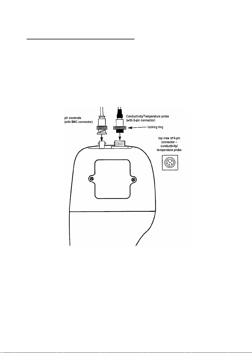
To connect the conductivity/temperature probe:
1. Line up the notch and 6 pins on the probe connector with the holes in the connector
located on the top of the meter. Push down and screw the metal sleeve to lock the probe
connector into place. See Figure 4.
2. To remove probe, unscrew the metal sleeve and slide up the probe connector. While
holding onto metal sleeve, pull probe away from the meter.
NOTE: Follow the same directions to connect an optional separate temperature element.
CAUTION: Do not pull on the probe cord or the probe wires might disconnect.
Figure 4: Connecting pH and conductivity/temperature probes

Instruction Manual PC 300
7
4 CALIBRATION
4.1 Important Information on Meter Calibration
When you re-calibrate your meter, old calibration points are replaced on a “point-by-point”
basis in pH, and on a “range-by-range” basis in conductivity.
For example:
• pH:
if you previously calibrated your meter at pH 4.01, 7.00, and 10.01, and
you re-calibrate at pH 7.00, the meter retains the old calibration data at pH
4.01 and pH 10.01.
• Conductivity:
If you previously calibrated your conductivity meter at 1413 µS
in the 0 to 1999 µS range and you re-calibrate at 1500 µS (which is also in the
0 to 1999 µS), the meter will replace the old calibration data (1413 µS) in that
range. The meter will retain all calibration data in other ranges.
• TDS:
If you previously calibrated your conductivity meter at 300 ppm in the 0
to 999 ppm range and you re-calibrate at 500 ppm (which is also in the 0 to
999 ppm), the meter will replace the old calibration data (300 ppm) in that
range. The meter will retain all calibration data in other ranges.
To view current calibration points:
• pH: Program P1.0 in the SETUP section
• Conductivity & TDS: Program P5.0 in the SETUP section
To completely re-calibrate your meter, or when you use a replacement probe, it is best to
delete the old calibration data by re-setting the meter.
To reset the meter to its factory defaults:
• pH: Program P4.0 in the SETUP section
• Conductivity & TDS: Program P9.0 in the SETUP section
NOTE: Re-setting the meter will set meter to factory defaults. Conductivity and pH must be
reset separately.
For directions on how to calibrate your meter:
• See section 4.3 for pH calibration.
• See section 4.4 for conductivity calibration.
• See section 4.4 for TDS calibration.
• See section 4.5 for Temperature calibration.

Instruction Manual PC 300
8
4.2 Prep aring the Meter for Calib ration
Before starting calibration, make sure you are in the correct measurement mode. When you
switch on the meter, the meter starts up in the measurement mode you shut it off in. For
example, if you shut the meter off in pH measurement mode, the meter will come back into pH
measurement mode when you switch the meter on.
4.3 pH Calibration
NOTE: We recommend that you perform at least 2-point calibration using standard
buffers that bracket (one above and one below) the expected sample range.
Preparing for pH calibration
This meter is capable of up to 5-point pH calibration to ensure accuracy across the entire pH
range of the meter. Select from the following buffer options:
• pH 1.68, 4.01, 7.00, 10.01 and 12.45 (USA)
• pH 1.68, 4.01, 6.86, 9.18, 12.45 (NIST)
The meter automatically recognizes and calibrates to these standard buffer values, which
makes pH calibration faster and easier.
Be sure to remove the protective electrode storage bottle or ru bber cap of t he electrode
before calibration or measurement. If the electrode has been s tored dry, wet the electrode
in tap water for 10 minutes before calibrating or taking readings to saturate the pH electrode
surface and minimize drift.
Wash your electrode in de-ionized water after use, and store in electrode storage solution. If
storage solution is not available, use pH 4.01 or 7.00 buffer solution.
Do not reuse buffer solutions after calibration. Contaminants in the solution can affect the
calibration and eventually the accuracy of the measurements. See Section on Accessories for
information on our high-quality pH buffer solutions.
Instruction Manual PC 300
9
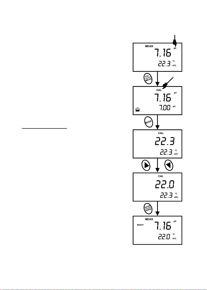
To Calibrate pH:
1. If necessary, press the MODE key to select pH
mode. The pH indicator appears in the upper right
hand corner of the display.
2. Rinse the prob e thoroughly with de-ionized water
or a rinse solution. Do not wipe the probe; this
causes a build-up of electrostatic charge on the
glass surface.
3. Dip the probe into the calibration buffer. The end of
the probe must be completely immersed into the
sample. Stir the probe gently to create a
homogeneous sample.
NOTE: The temperature element is in the conductivity
cell. For temperature compensated readings, dip
the conductivity cell into the calibration buffer as
well.
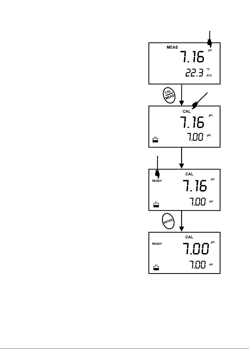
4. Press CAL/MEAS to enter pH calibration mode.
The CAL indicator will be shown. The primary
display will show the measured reading while the
smaller secondary display will indicate the pH
standard buffer solution.
5. Wait for the measured pH value to stabilize. See
Figure 5.
Figure 5 - pH Calibration
Instruction Manual PC 300
10
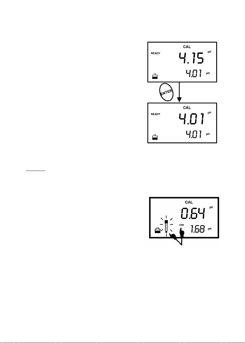
6. Press ENTER to confirm calibration. The meter is
now calibrated to the current buffer. The lower
display scrolls through the remaining buffer options.
• If you are performing multi-point calibration, go
to step 7.
• If you are performing one-point calibration, go
to step 9.
7. Rinse the electro de with de-ionized water or in rinse
solution, and place it in the next pH buffer.
8. Follow steps 5 to 8 for additional calibration points.
See Figure 6.
9. When calibration is complete, press CAL/MEAS to
return to pH measurement mode.
NOTES:
To exit from pH calibration mode without
confirming calibration, DO NOT press ENTER in
step 6. Press CAL/MEAS instead.
If the selected buffer value is not within ±1.0 pH from
the measured pH value: the electrode and buffer icon
blink and the ERR annunciator appears in the lower left
corner of the display. See Figure 7.
To limit the number of pH buffer values available during
calibration, see SETUP section P3.2.
Figure 6 - Next point calibration for
pH 4.01
Figure 7 - Err message and
electrode icon will appear if
incorrect buffer are used

Instruction Manual PC 300
11
4.4 Conductivity Calibration
The PC 300 meter has five measuring ranges. You can calibrate one point in each of the
measuring ranges (up to five points). If you are measuring values in more than one range,
make sure to calibrate each of the ranges you are measuring. All new calibration data will
over-ride existing stored calibration data for each measuring range you calibrate.
• If you are measuring in ranges near to or greater than 20 mS (10 ppt), or
near to or lower than 100 µS (50 ppm), calibrate the meter at least once
a week to get specified ±1% F.S. accuracy.
• If you are measuring in the mid ranges and you washed the probe in
deionized water and stored it dry, calibrate the meter at least once a
month.
• If you take measurements at extreme temperatures, calibrate the meter
at least once a week.
Preparing for conductivity calibration
For best results, select a standard value close to the sample value you are measuring.
Alternatively use a calibration solution value that is approximately 2/3 the full-scale value of
the measurement range you plan to use. For example, in the 0 to 1999 µS conducti vity range,
use a 1413 µS solution for calibration.
Table 1 - Range Indicator and its corresponding ranges
Range
indicator
Conductivity
Range
Recommended Calibration
Solution Range
TDS Range Recommended Calibration
Solution Range
r 1
0.00 Æ 19.99 µS 6.00 to 17.00 µS
0.00 Æ 9.99 ppm 3.00 to 8.50 ppm
r 2
0.0 Æ 199.9 µS 60.0 to 170.0 µS
10.0 Æ 99.9 ppm 30.0 to 85.0 ppm
r 3
0 Æ 1999 µS 600 to 1700 µS
100 Æ 999 ppm 300 to 850 ppm
r 4 0.00 Æ 19.99 mS 6.00 to 17.00 mS 1.00 Æ 9.99 ppt 3.00 to 8.50 ppt
r 5 0.0 Æ 199.9 mS 60.0 to 170.0 mS 10.0 Æ 200 ppt 30.0 to 170 ppt
Temperature Coefficient: These meters are factory set to a temperature coefficient of 2.1 %
per °C. For most applications this will provide good results. See Program P8.1 in
Section 7.9 to set the temperature coefficient to different value. See Addendum 3,
“Calculating Temperature Coefficients” to determine the appropriate temperature
coefficient for your solution.
Normalization Temperature: The factory default value for normalization temperature is 25
°C. If you need to normalize to a value other than 25 °C, see Program P8.2 in Section
7.9.
Instruction Manual PC 300
12
Do not reuse calibration solutions after calibration. Contaminants in the solution can affect the
calibration, and eventually the accuracy of the measurements. Use fresh calibration solution
each time you calibrate your meter.
All new calibration data will over-ride existing stored calibration data for each measuring range
calibrated.
Calibrating for Conductivity:
1. If necessary, press the MODE key to select
conductivity mode.
2. Rinse the probe thoroughl y with de-ionized water
or a rinse solution, then rinse with a small amount
of calibration standard.
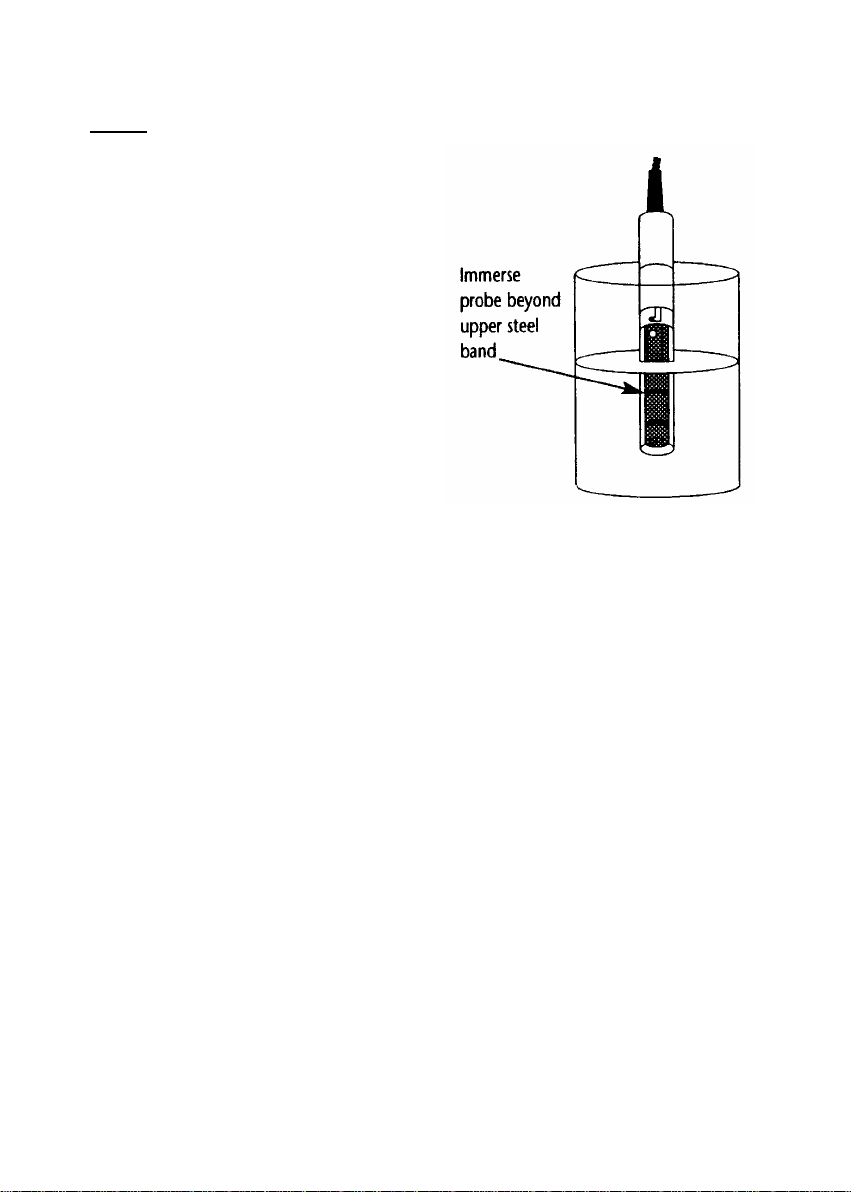
3. Dip the probe into the calibration standard.
Immerse the probe tip beyond the upper steel
band. Stir the probe gently to create a
homogeneous sample. See Figure 8.
4. Wait for the measured conductivity value to
stabilize. If the READY indicator has been
activated (SETUP program P7.1), the READY
annunciator lights when the reading is stable.
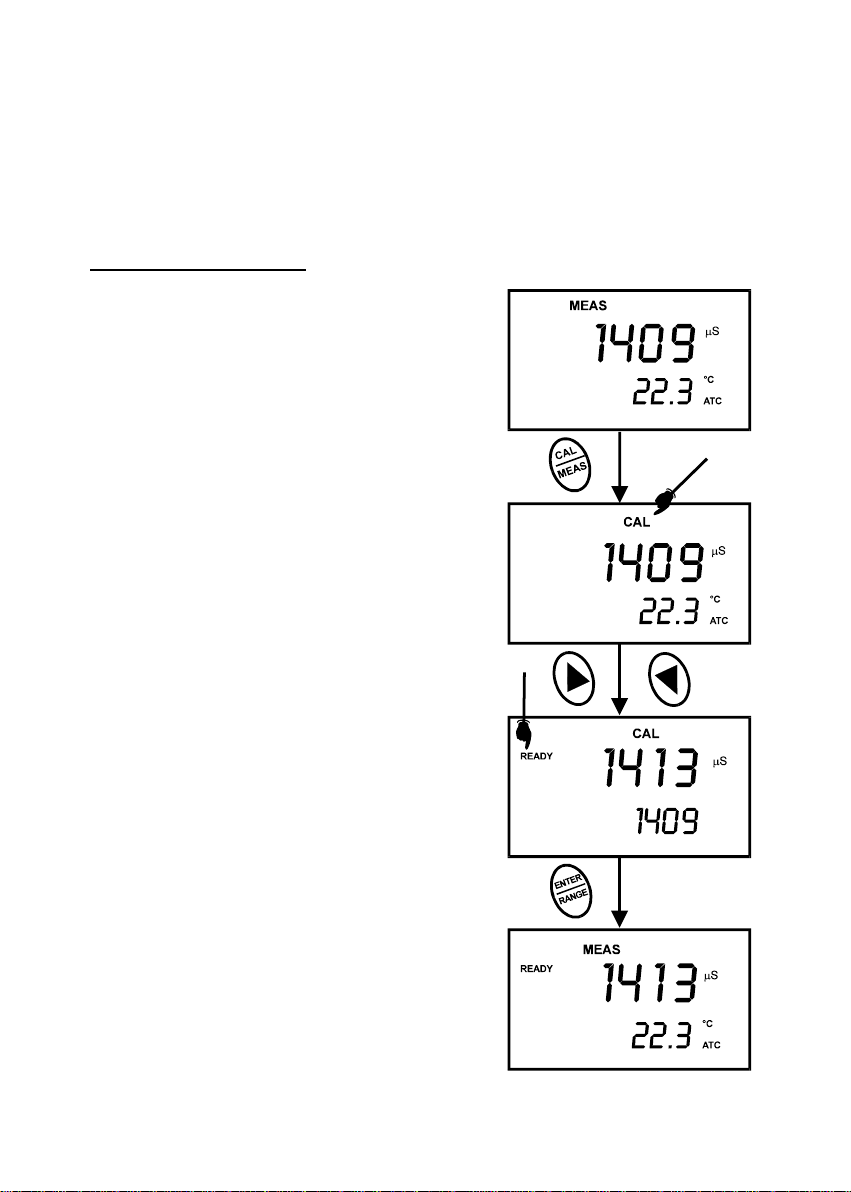
5. Press CAL/MEAS to enter conductivity or TDS
calibration mode. The CAL indicator will appear in
the upper right corner of the display.
6. Press the or keys to chang e the value on the
primary display to match the value of the
calibration standard.
7. Press ENTER to confirm calibration value. The
meter returns to the MEAS (measurement) mode.
8. Repeat steps 1 to 7 for other measuring ranges.
See figure 8.
Figure 8 - Conductivity Calibration
Instruction Manual PC 300
13
NOTES:
When entering calibration mode, the meter will
display the factory default value. If the meter
was previously calibrated, the display may
“jump” to the factory default value when
switching from measurement to calibration
mode.
To exit from Conductivity calibration mode
without confirming calibration, DO NOT
press the ENTER key in step 7. Press
CAL/MEAS instead. This will retain the
meter’s old calibration data in the measuring
range of the calibration.
You can offset the conductivity reading up to
± 40% from default setting. If your measured
value differs by more than ± 40%, clean or
replace probe as needed.
Eutech Instruments/ Oakton Instruments offers a wide selection of high-quality calibration
standards. See section on Accessories for more information.
Figure 9 - Proper Immersion of
the conductivity probe
Instruction Manual PC 300
14
4.5 TDS Calibration
4.5.1 Calibrating for TDS directly
The factory default setting for TDS conversion factor is
0.5. If your solution has a different TDS factor, you can
improve calibration accuracy by setting the TDS factor
prior to calibration. See P7.4 for directions.
1. If necessary, press the MODE key to select TDS
mode.
2. Rinse the probe thoroughly with de-ionized water or
a rinse solution, then rinse with a small amount of
calibration standard.
3. Dip the probe into the calibration standard. Immerse
the probe tip beyond the upper steel band. Stir the
probe gently to create a homogeneous sample.
Allow time for the reading to stabilize.
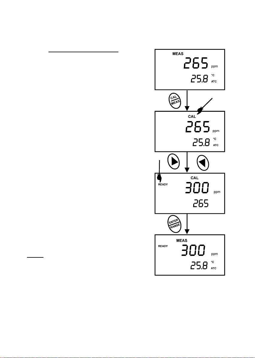
4. Press CAL/MEAS to enter TDS calibration mode.
The CAL indicator will appear in the upper right
corner of the display.
5. Press the or keys to change the value on the
primary display to match the value of the calibration
standard.
6. Press ENTER to confirm the calibration value. The
meter returns to the MEAS (measurement) mode.
See Figure 10.
7. Repeat steps 1 to 6 for other measuring ranges.
NOTES
To exit from TDS Calibration mode without confirming
calibration, DO NOT press the ENTER key in step 6.
Press CAL/MEAS instead. This will retain the meter’s old
calibration data in the measuring range of the calibration.
You can offset the TDS reading up to ± 20% from the
default setting. If your measured value differs by more
than ± 40%, clean or replace probe as needed.
Figure 10 - TDS Calibration

Instruction Manual PC 300
15
4.6 Calibration with Conductivity Standard and TDS factor
The concentration of salts dissolved in solution increases the conductivity of that solution. This
relationship varies from salt to salt and is roughly linear over a given range for a given salt.
The TDS conversion factor is the number used by the meter to convert from conductivity to
TDS.
Instead of calibrating for TDS directly (described above), you can calibrate the PC 300 meter
by:
1. calibrating to conductivity standards (as described above) and then
2. entering the appropriate TDS conversion factor into the meter.
To determine the conductivity to TDS conversion factor for your solution:
• Addendum 1 lists some commonly used conversion factors.
• Addendum 2 describes how to calculate the TDS conversion factor for other
solutions.
Enter the TDS conversion factor into your meter as described under Section 7.5, in P7.4
Setting the TDS Factor.
Instruction Manual PC 300
16
4.7 Te mperature Calibration
The conductivity electrode (EC-CONSEN91W/ 35608-50)
supplied with the meter has a built-in temperature sensor. In
addition you can also use a separate temperature sensing
element supplied by Eutech Instruments (as such
temperature probe (EC-PHWPTEMP-01W/ 35618-05), or the
“3-in-1” pH/Temperature combination electrode, (EC-
FE73528-01W/ 35808-71) for ATC purpose.
The conductivity probe is factory calibrated. Temperature
calibration can be done only if you suspect temperature
errors that may have occurred over a long period of time, or if
you have a replacement probe.
Temperature calibration is accessible during pH or
conductivity or TDS calibration.
Temperature Calibration
1. Make sure the conductivity electrode (or temperature
probe or “3-in-1” electrode) is attached to the 6-pin
connector.
2. Switch the meter on.
3. Press the CAL/MEAS key to enter calibration mode
(either from pH or conductivity mode). The CAL
indicator will appear above the primary display.
4. While in pH (or conductivity or TDS) calibration mode,
press the MODE key to enter temperature calibration
mode. The primary display shows the last set
temperature value and the secondary display shows the
temperature reading with zero offset.
5. Dip the ATC probe into a solution of known temperature
(i.e. a temperature bath). Allow time for the temperature
probe to stabilize.
Figure 11 - Temperature
Calibration in pH mode.

Instruction Manual PC 300
17
6. Scroll with the and keys to set the correct temperature value (i.e. the temperature of
the temperature bath). You can adjust the reading increments of 0.1 °C.
7. Once you have selected the correct temperature press the ENTER key. The meter
automatically returns to pH measurement mode. See Figure 11.
NOTES:
• You can offset the temperature reading up to ±5 °C from original reading.
• To exit this program without confirming the temperature calibration value,
DO NOT press ENTER. Press CAL/MEAS instead.
Instruction Manual PC 300
18
5 MEASUREMENT
5.1 Taking pH Measurements
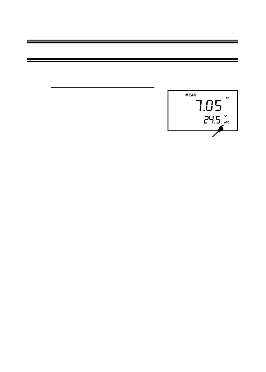
5.1.1 Automatic Temperature Compensation
Automatic Temperature Compensation only occurs when a
temperature sensing element is plugged into the meter.
Temperature sensing element refers to the following probes
made specifically for this meter:
• The conductivity electrode (EC-CONSEN91W/
35608-50) with a built-in temperature sensor;
• Temperature probe (EC-PHWPTEMP-01W/
35618-05); or
• The “3-in-1” pH/Temperature combination
electrode (EC-FE73528-01W/ 35808-71).
If there is no temperature sensor plugged into the meter, the default manual temperature
setting is automatically 25 °C. You can manually set the temperature to match your working
conditions using a separate thermometer.
For automatic temperature compensation (ATC) simply plug the temperature probe into the
meter (see page 6 for directions). The ATC indicator will light up on the LCD. See figure 12.
NOTE: The temperature sensing element must be submersed in the liquid yo u are
measuring.
Figure 12 - ATC annunciator will
light up when connected to
temperature probe
 Loading...